Abstract
Cutting force is one of the most important factors in the ultrasonically assisted grinding (UAG) of hard and brittle materials. Many theoretical and experimental studies show that UAG can effectively reduce cutting forces. The existing models for UAG mostly assume an ideal grinding wheel with abrasives in both the end and lateral faces to accomplish material removal, whereas the important role of the transition fillet surface is ignored. In this study, a theoretical cutting force model is presented to predict cutting forces with the consideration of the diamond abrasives in the end face, the lateral face, and the transition fillet surface of the grinding tool. This study analyzed and calculated the vibration amplitudes and the cutting forces in both the normal and tangential directions. It discusses the influences of the input parameters (rotation speed, feed rate, amplitude, depth and radius of transition fillet) on cutting forces. The study demonstrates that the fillet radius is an important factor affecting the grinding force. With an increase in fillet radius from 0.2 to 1.2 mm, the grinding force increases by 139.6% in the axial direction and decreases by 70% in the feed direction. The error of the proposed cutting force model is 10.3%, and the experimental results verify the correctness of the force model.
1. Introduction
With the development of science and technology, many advanced materials such as hard and brittle materials, super alloys and composites are widely used in the aerospace, electronics, medical and automotive industries [1]. Among the advanced materials, the hard and brittle materials, such as the silicon carbide ceramics, sapphire and optical glass, exhibit outstanding properties, including high hardness, excellent corrosion resistance, high temperature resistance and wear resistance. The traditional processing methods do not meet the industrial requirements. These methods have a low material removal rate and suffer from serious tool wear and even breakage, which limits their applications [2].
The K9 optical glass is a typical hard and brittle material that is difficult to process. Extensive research demonstrates that UAG can effectively reduce tool wear and suppress breakage in the machining of hard and brittle materials at a high machining efficiency and reduced material damage [3,4].
Ultrasonically assisted grinding (UAG) is traditionally a hybrid machining process in which ultrasonic vibration is imposed on a grinding tool or workpiece for alternative material removal mechanisms [1]. UAG has become one of the advanced processing techniques for the advanced machining processes in the machining of hard and brittle materials. The advantages include: reduced grinding force [5], reduced grinding temperature [6], reduced surface and subsurface damage [7,8].
In the machining of hard and brittle materials, the machining force is an essential factor affecting the surface integrity of a workpiece [9,10], the wear and lifetime of a grinding wheel [11,12], and the material removal rate [13], etc. Therefore, it is necessary to establish a model for predicting grinding forces so as to achieve good surface integrity, grinding efficiency and extended tool life.
In the existing literature, there are extensive studies on the modelling material removal rate during UAG [14]. Pei [15] proposed a modeling method of material removal rate based on the ultrasonic machining of ceramic materials, carried out experimental verification, and further deduced the relationship between the material removal rate and machining parameters. Lee [16] deduced the model of cutting force and material removal rate of ultrasonic machining ceramic matrix composites and verified that the increase in machining parameters would lead to the increase in material removal rate and the coarsening of the machined surface. Pei [17] proposed an approach to modeling the ductile-mode removal in rotary ultrasonic machining. Li [18] carried on a varied-depth nano-scratch test of single grain on a nano indentation system and based on the varied-depth nano scratch test and the grain trajectory of ultrasonic vibration-assisted grinding (UVAG), a theoretical model of the normal grinding force is acquired using the material removal in unit time as a bridge. Pereverzev [19] developed the mathematical model of cylindrical grinding and obtained the grinding wheel blunt and abrasive removal rate.
However, there are few reports on the predictive models of cutting forces during the UAG of hard and brittle materials. During the axial ultrasonically assisted grinding, the diamond grains in the end face of a tool is forced to generate the intermittent hammering action [12,15]. Based on the impulse theory and brittle fracture theory, Pei et al. established a cutting force model of a core tool for machining holes and tested it on titanium alloy [20], hard and brittle materials [21] and composite materials [22] with the rotary UAG. Wu [23] proposed a grinding force model considering both ductile the removal force and brittle removal force, which was verified by experiments. Li [24] developed a grinding force model for micro-grinding of reaction-bonded silicon carbide ceramics. Zhang et al. [25] extended the cutting force model to the face milling and proposed a mathematical model for cutting forces in the rotary ultrasonic face milling. However, the models established by either Pei or Zhang only considered the influence of the diamond grains in the end face of the tool. Wang et al. [26,27] considered that the effective diamond grains in the lateral face of the tool generated a continuous contact in a sinusoidal trajectory and established a grinding force model based on the brittle fracture theory. However, in the case of grinding at a cutting depth larger than the protrusion height of the abrasives, the material removal is realized by the abrasive grains not only at the end face but also at the lateral face. Therefore, on the basis of the above existing cutting force model, with the consideration of the diamond grains in both the end and lateral faces of the tool, Xiao et al. [28] proposed a cutting force model for the rotary ultrasonic milling of dental zirconia ceramics.
The existing studies of the cutting force model of UAG only considered the influence of the diamond grains in either the end face or the lateral face of the tool. In the existing studies, the cutting force was the primary cause responsible for edge chipping and surface integrity. From the study of Pei [29,30] and Yang [31], the maximum stress was found in the transition fillet and the surrounding surfaces of the tool. No studies to date have considered the influence of diamond grains in the transition fillet surface. In an exploratory grinding experiment of SiC, the wear of a diamond grinding wheel was identified mainly in the transition fillet and the surrounding surfaces, as shown in Figure 1, which implies that the diamond grains on the transition fillet surface have a great influence on the cutting force.
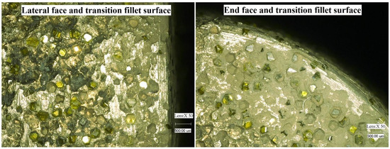
Figure 1.
Wear of the tool surface after grinding.
In this paper, an improved mechanistic model for predicting cutting forces based on the K9 optical glass in UAG was developed by considering the influence of the diamond grains in the transition fillet surface for the first time. Firstly, the force analysis of the effective abrasive grains in the end face, lateral face and the transition fillet surface of the tool was carried out. Secondly, the cutting forces of a single abrasive grain in the end face, lateral face and the transition fillet surface of the tool are calculated separately. Then, the cutting force model was established by integrating the forces on all effective abrasive grains. In modeling the cutting forces caused by the abrasive grains in the transition fillet surface, variations of the normal and tangential forces on the contact surface between the grains and workpiece were analyzed. Finally, the unknown parameters of the cutting force model were obtained through experiments and calculations, and the model was verified through slot grinding experiments.
2. Model Development
2.1. Kinematic Analysis of Diamond Grains
In axial ultrasonically assisted grinding, the removal of materials can be thought of as the combination of the actions of the whole active abrasive particles, and the basic kinematics of UAG is shown in Figure 2. Taking the single abrasive grain into consideration, an abrasive grain consists of rotational motion, ultrasonic vibration, and feed motion. Therefore, the motion trajectory of an abrasive grain in UAG can be expressed as
where r is the rotational radius of the abrasive grain, ω is the angular velocity of the abrasive grain (ω = 2πnr/60, nr is the rotation speed of the tool), νF is the feed rate, A is the vibration amplitude, f is the ultrasonic vibration frequency. Figure 3 shows the trajectory of an abrasive particle in UAG.
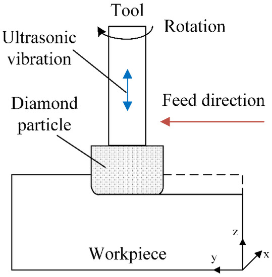
Figure 2.
Illustration of ultrasonically assisted grinding process.
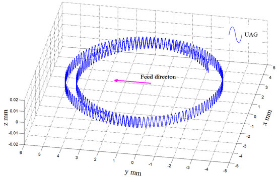
Figure 3.
Trajectory of an abrasive grain in UAG.
The velocity and acceleration of abrasive grains can be obtained by differentiating Equation (1), which can be derived as
2.2. Cutting Force Analysis
Due to the introduction of the axial ultrasonic vibration, the diamond grains in the end face of the tool are vibrated as perpendicular to the workpiece surface, and those in the lateral face are parallel to the workpiece surface, while those in the transition fillet surface penetrate into the workpiece surface at a certain angle. Therefore, the abrasive grains at different locations of the tool result in different cutting forces because of their different ways of interacting with the workpiece. In this study, assumptions and simplifications are made as follows:
- All abrasive grains are rigid indenters with an octahedral shape. The semi-angle between the two opposite edges of an abrasive grain is β, and the length of the edges is b, as shown in Figure 4;
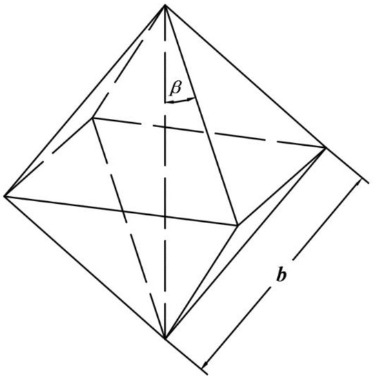 Figure 4. A diamond grain simplified as an octahedron.
 - The material is ideally removed by brittle fracture;
- All the diamond grains in the tool surface have the same protrusion height and are uniformly distributed.
In consideration of different cutting depths, the process of axial ultrasonically assisted grinding contains two cases: case one is ap > rc, as shown in Figure 5, and the other is ap < rc, as shown in Figure 6 (where ap is cutting depth, rc is the radius of the transition fillet). In the literature, the diamond grains in the end face of the tool generate the intermittent hammering actions primarily in the axial direction [12,15]. The diamond grains in the lateral face of the tool generate a continuous contact with sinusoidal trajectory primarily in the feed direction [26,27,28]. The cutting state of the abrasive grains in the transition fillet surface is more complex and may not only consist of the intermittent hammering actions but also the continuous contact actions.
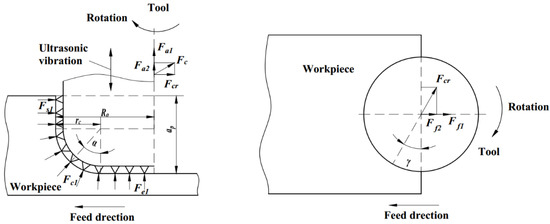
Figure 5.
Cutting force analysis of ap > rc.
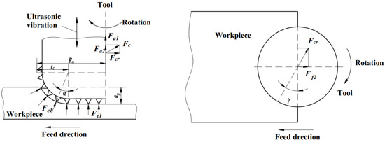
Figure 6.
Cutting force analysis of ap < rc.
Decomposition can be made on the cutting forces generated by the abrasive grains in the different areas of the tool in both the axial and feed directions. For the case of ap > rc, it is obtained that Fa = Fa1 + Fa2 and Ff = Ff1 + Ff2, as shown in Figure 5. For the case of ap < rc, Fa = Fa1 + Fa2 and Ff = Ff2 are found, as shown in Figure 6. The parameters in the above equations are defined as:
- Fa is the axial force of the tool;
- Fc is the cutting force of the diamond grains on the transition fillet surface of the tool;
- Fa1 is the axial force of the diamond grains on the end face of the tool;
- Fa2 is the component of Fc in the axial direction;
- Ff is the feed force of the tool;
- Ff1 is the feed force of the diamond grains in the lateral face of the tool;
- Ff2 is the component of Fc in the feed direction.
Through the above analysis, the cutting force in UAG can be expressed as
Since the radial force of the tool is too small to have any impact effect, it was not considered in this study. For the cutting force model, the indentation theory on brittle materials is used, as illustrated in Figure 7. CL and Ch are the lateral crack length and height, respectively, and are given by [32,33,34]:
where Cc and Cb are dimensionless constants; E is the elastic modulus; HV is the hardness; KIC is the fracture toughness; ν is the Poisson’s ratio; and δ is the maximum penetration depth.
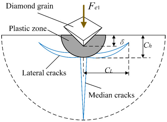
Figure 7.
Illustration of cracks induced by a diamond grain.
2.3. The Axial Force from the Diamond Grains in the End Face
2.3.1. Equivalence Relation between Fa1 and Fe1
The diamond grains in the end face of the tool are not in continuous contact with the work-piece due to its oscillatory motion. Figure 8 shows the trajectory of an abrasive grain during one cycle of ultrasonic vibration. In one period of oscillation, the diamond grain makes contact with the workpiece during the effective cutting time (Δt). The maximum impact force (Fe1) is generated while the active abrasive grain reaches its maximum depth (δ) [21]. The maximum force can be calculated as follows:
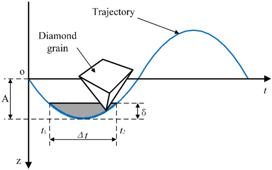
Figure 8.
Trajectory of a diamond grain during one cycle of ultrasonic vibration.
The effective cutting time can be calculated through the following equation [9,15]:
The maximum impact force produced by each abrasive grain in the end face of the tool is assumed to be the same. Based on the impulse theory, the impulse in terms of the cutting force produced by the abrasive grains in the end face during one cycle of ultrasonic vibration is [15]:
where Ie1 is the impulse in terms of the cutting force produced by one abrasive grain, ; Ne is the number of active abrasive grains in the end face of the tool [20], ,; A0 is the area of the abrasive grains distribution; ρ is the density of diamond material, ρ = 3.52 × 10⁻³ g/mm3; Ca is the abrasive concentration, Ca = 100%; Ro is the outer radius of the tool, Ri is the inner radius of the tool.
During one cycle of ultrasonic vibration, the impulse of the axial force Fa1 can be obtained in the following:
then:
2.3.2. Relationship between Fe1 and δ
The crossing of the lateral cracks produced by the adjacent abrasive grains can lead to the material removal. The volume of the material removed can be calculated based on the size of the lateral cracks produced. For an abrasive grain in the end face of the tool, the volume of material removed in fracture zone (Ve1) can be simplified as the volume of tetrahedron ABCDE [20], as shown in Figure 9:
where K is the volume correction parameter for the consideration of overlapping of the removed volume and various protrusive height; Le1 is the effective cutting distance that an abrasive grain moves during Δt, ; D is the diameter of the circle where a diamond grain is located, and can be calculated as .
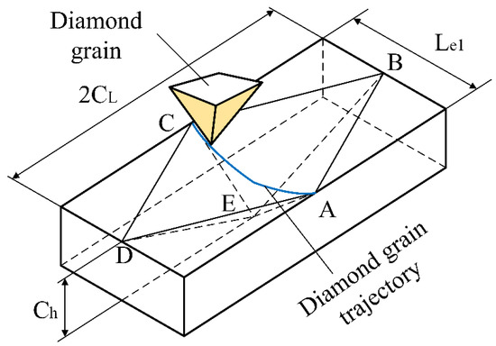
Figure 9.
The calculation of the volume of material removed by one abrasive grain.
During one cycle of ultrasonic vibration, the material removal rate by the active abrasive grains in the end face can be calculated as
For the given input parameters, the volume of the material removed can be expressed. As shown in Figure 10, for ap > rc, all abrasive grains in the transition fillet surface contributed to material removal, whereas for ap < rc, only partial abrasive grains contributed to material removal. Therefore, during an ultrasonic vibration cycle, the amount of material removed by the active abrasive grains in the end face or the transition fillet surface can be expressed in Equation (14). Where Vue is volume removed by the active abrasive grains in the end face [28], he is the protrusive height of the abrasive grains, Vuc is volume removed by the active abrasive grains in the transition fillet surface. Rom is the maximum contact radius of the tool, , where :
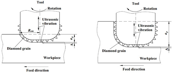
Figure 10.
The relationship between cutting depth and work-piece removal volume.
Hence, during one cycle of ultrasonic vibration, the material removal rate due to the active abrasive grains in the end face can also be calculated as
By equating Equations (13) and (15), the relationship between Fe1 and δ can be obtained by the following equation:
where , [25,28].
2.3.3. Modelling the Axial Cutting Force Fa1
With the simultaneous Equations (7), (11) and (16), the axial cutting force produced by an abrasive grain in the end face of the tool is calculated by
Hence, the axial cutting force produced by all the abrasive grains in the end face of the tool can be calculated by
2.4. The Feed Direction Cutting Force from the Diamond Grains in the Lateral Face
The effective diamond grains in the lateral face of the tool generate a continuous contact with a sinusoidal trajectory. Shown in Figure 11 is the trajectory of a diamond grain in the lateral face. The trajectory length of a diamond grain contact with the workpiece in one rotational period is obtained from Equation (2):
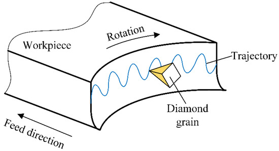
Figure 11.
Trajectory of an abrasive grain on the lateral face.
If the input parameters are given, the material removal rate during a single rotational period can be expressed as
Assume the maximum impact force (Fs1) produced by each abrasive grain in the lateral face of the tool is also the same, and cutting depth is constant at a low feed rate. Therefore, the material removal rate during a single rotational period is obtained [28]:
where Ns is the number of active abrasive grains in the lateral face, ; Ks is a volume correction parameter for the consideration of the overlapping of the removed volume of material and various protrusive heights. The analysis method is similar to that used in calculating the number of the active grains in the end face of the tool.
By equating Equations (20) and (21), the maximum impact force produced by an abrasive grain in the lateral face is obtained:
Hence, through integrating the forces produced by all the active abrasive grains, the feed direction cutting force from the lateral face of the tool is obtained:
2.5. Cutting Force from the Diamond Grains in the Transition Fillet Surface
2.5.1. The Analysis of Cutting Force
The diamond grains in the transition fillet surface penetrate into the workpiece at an angle α. The normal and tangential ultrasonic vibrations of the diamond grains in contact with the workpiece have variable amplitudes, as shown in Figure 12. An and At are the vibration amplitudes in the normal and tangential directions, respectively. Due to the feed motion of the tool, the normal and tangential feed rates of the diamond tool are also changed with the penetration angle α, where the normal feed rate can be expressed as νn = νFsinα, and the tangential feed rate as νt = νFcosα:
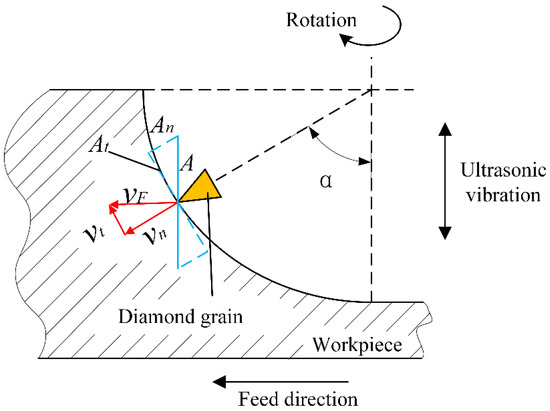
Figure 12.
Analysis of vibration amplitude and the feed rate of diamond grain on the transition fillet surface.
From Figure 12, the normal and tangential ultrasonic vibration amplitudes of the abrasive grains in the transition fillet surface are calculated by An = Acosα, An = Asinα. Therefore, variations in the normal and tangential ultrasonic vibration amplitudes of the diamond grains in the lateral face are shown in Figure 13a,b, respectively.
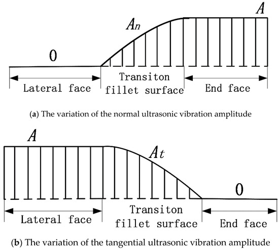
Figure 13.
The variation of the ultrasonic vibration amplitude on different tool surface.
Due to the variation in the ultrasonic vibration amplitude, the cutting force of an abrasive grain on the transition fillet surface (Fc1) changes with α. In consequence, the variation in the normal ultrasonic vibration amplitude leads to the intermittent hammering action at the end face abrasive grains, whereas the variation in the tangential ultrasonic vibration amplitude leads to a continuous contact in a sinusoidal trajectory. As a result, the cutting force Fc1 is a sum of the cutting forces produced by the former two modes of contact between the tool and the workpiece:
where Fe1′ and Fs1′ are the cutting forces caused by the variations in both the normal and tangential ultrasonic vibration amplitudes, respectively.
2.5.2. Modeling of Cutting Forces Fa2 and Ff2
Substituting Rom, An, Nc and νt into Equations (11)–(16), Fe1′ can be derived as follows:
where Nc is the number of active abrasive grains in the transition fillet surface: , and .
Hence, the axial cutting force from the diamond grains in the transition fillet surface is obtained:
Meanwhile, substituting Rom, At, Nc and νn into Equations (19)–(23), Fs1′ is obtained as
where Ls′ can be derived through substituting the Rom and νn for Ro and νF in Equation (19).
As a result, the feed direction cutting force from the diamond grains in the transition fillet surface is obtained:
2.6. Cutting Force Model in UAG
Substituting Equations (18), (23), (26) and (28) into Equation (4), one can obtain the axial cutting force of the tool in UAG:
The feed direction cutting force of the tool in UAG is:
where if ap > rc, α = π/2; if ap < rc, τ = 0.
Figure 8 shows the trajectory of an abrasive grain during one cycle of ultrasonic vibration.
The units of parameters involved in the formula are shown in Table 1.

Table 1.
The units of parameters in the formulas.
3. Obtaining K and Ks
3.1. Experimental Setup
Experiments were carried out on a self-developed ultrasonic vibration system which was able to generate ultrasonic vibrations in a frequency range of 16 kHz. A YDCB-05 piezoelectric dynamometer (DUT, China) was used to measure the cutting forces, the resolution was ±0.001 N, and both the linear error and the reproducibility error were less than ±1%. A LK-H025 laser displacement sensor (KEYENCE, Japan) was utilized to measure the vibration amplitude while the tool was in rotation, and the repeat accuracy was 0.1 μm. The grinding wheels used in the experiments were provided by CPTC company. The grinding wheels were diamond core tools of a metal bond. They had an outer diameter of 10 mm and an inner diameter of 4 mm, and a radius of transition fillet in four different sizes: 0.2 mm, 0.7 mm, 1 mm and 1.2 mm. The workpiece material was the K9 optical glass with the dimensions of 15 × 30 × 60 mm. The mechanical properties of the workpiece are shown in Table 2. Slot grinding was used in the experiments, as shown in Figure 14.
Table 2.
Mechanical properties of K9 optical glass.
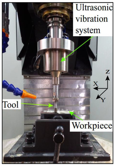
Figure 14.
Experimental setup.
The relationship between volume correction parameters (K and Ks) and input variables (nr, A, vF, ap, rc) is shown in Equation (29) and Equation (30), and the input variables may have influence on the value of the volume correction parameters. Therefore, the experiments on the influence of the input variables were carried out. The experimental design is shown in Table 3.
Table 3.
Experimental conditions for obtaining K and Ks.
3.2. Analysis of Experimental Results
Substituting the average axial and feed forces measured from the experiment into Equations (29) and (30), volume correction parameters K and Ks can be solved. Figure 15 shows the values of K and Ks calculated through each experimental group.
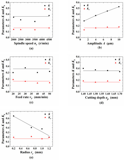
Figure 15.
Influences of input variables on the value of K and Ks: (a) spindle speed nr; (b) amplitude A; (c) feed rate vF; (d) cutting depth ap; and (e) radius rc.
Figure 15a,c,d show that K is basically a constant with a value of 0.37. It was seen that nr, vF, ap have a minor effect on the value of K. Figure 15a–e show that Ks is basically a constant with a value of 0.166. It was shown that the input variables (nr, A, vF, ap, rc) have a minor effect on the values of Ks. However, Figure 15b,e show that the value of K noticeably increases as the vibration amplitude A increases, and decreases as the radius rc increases. It is indicated that the input variables of A and rc have strong effects on the value of K. Equation (31) is used to express the relationship between K and the input variables A and rc. The values of indices in Equation (31) are obtained by the least squares estimation (LSE) method as a0 = 0.617, a1 = 0.261, a2 = −0.393:
4. Model Prediction and Experimental Verification
4.1. Model Prediction
By substituting the values of volume correction parameters into the cutting force model, numerical simulation can be carried out. Then, the relations between input variables and the axal and feed direction forces are obtained, as shown in Figure 16.
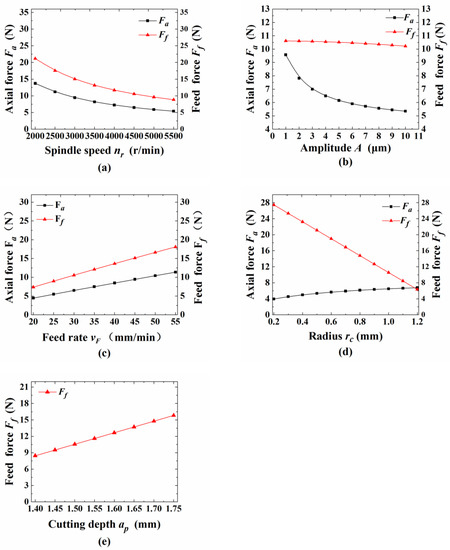
Figure 16.
Predicted relation between the variables and the cutting force: (a) spindle speed nr; (b) amplitude A; (c) feed rate vF; (d) radius rc; and (e) cutting depth ap.
The axial force decreases as the vibration amplitude increases, which is depicted in Figure 16b. The ultrasonic vibration can effectively reduce the axial force because the trend in decreasing force is large. In addition, the feed direction force decreases as the amplitude increases, which may be explained by an increased trajectory of the lateral abrasive grains.
Figure 16d shows the predicted relation between the radius of the transition fillet and the cutting force. It can be seen that the axial force increases as the radius increases. The main reason is that the number of active diamond grains in the end face decreases as the radius of transition fillet increases. Correspondingly, the material removal by the actions of intermittent hammering decreases. This result is consistent with the fact that the cutting force is larger as the tool wear condition becomes serious. However, the number of active diamond grains in the lateral face decreases as the radius of the transition fillet increases, which contributes to the decrease in the feed force.
4.2. Experimental Verification
The experiments were all carried out on the same equipment. The values of the input variables for the verification experiments are shown in Table 4.
Table 4.
The values of input variables for the experimental verification.
Comparison of the cutting forces between the experimental and theoretical values are shown in Figure 17 and Figure 18. It can be seen that the theoretical results agree well with the experimental results with a total relative mean error of 10.3%. As shown in Figure 17b and Figure 18b, with an increase in the amplitude, the influence degree on the axial force decreases from 19.3% to 14.2%. However, the influence degree on the feed force increases from 3.7% to 15.4%. As shown in Figure 17d and Figure 18e, the radius of the transition fillet has a large influence on the cutting force. The axial force increases as the radius of the transition fillet increases, but the feed force decreases. The result also proves the necessity and suitability of the cutting force model established by considering the radius of the transition fillet.
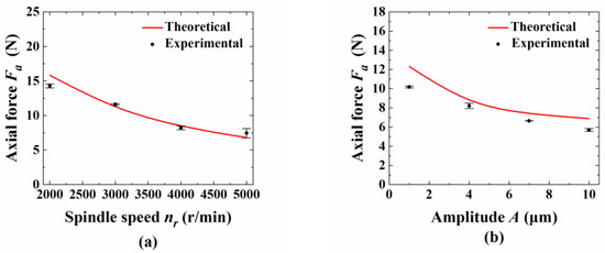
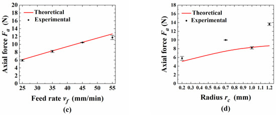
Figure 17.
The comparison of the axial direction force between experimental results and predicted results: (a) spindle speed nr; (b) amplitude A; (c) feed rate vF; and (d) radius rc.
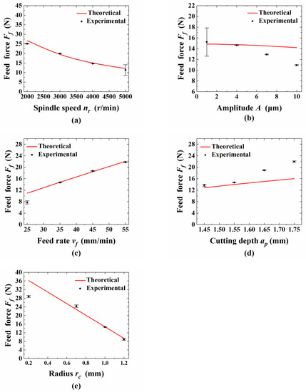
Figure 18.
Comparison of the feed direction force between the experimental results and predicted results: (a) spindle speed nr; (b) amplitude A; (c) feed rate vF; (d) cutting depth ap; and (e) radius rc.
Based on the results of the experiment with the input variables in Table 4, the values of the correction parameters in the model of Zhang [25] and Xiao [28] can be recalculated. Then, the cutting forces can be predicted though their models. Since the model in this paper is based on the fillet radius of the grinding wheel, the selected grinding depth is larger than the fillet radius of the tool, so the grinding depth parameter is larger, but the range of other parameters is basically the same.
The comparison between the results with the theoretical values of the presented model and the experimental results, as shown in Figure 19, show that the axial force varies with the different spindle speeds and amplitudes and the feed force varies with the different spindle speeds as examples to show the comparative results. It can be seen that the prediction accuracy of the presented model is superior to that of others, which also proves the reliability of the presented model.
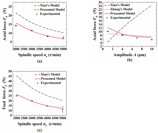
Figure 19.
Comparison of the presented model and others’ models: (a) axial force Fa—spindle speed nr; (b) axial force Fa—amplitude A; and (c) feed force Ff -feed rate vF.
An interesting phenomenon was observed. The edge chipping of the slot was decreased through an increase in the radius of the transition fillet. This phenomenon might be caused by the decrease in the feed force. The cutting force model can also be applied to the grinding of other hard and brittle materials, such as ceramics.
5. Conclusions
A predictive cutting force model was developed with the consideration of the influence of diamond grains in the transition fillet surface of the tool for predicting cutting forces in UAG. During the calculation of the cutting force, volume correction parameters K and Ks are used for the consideration of the overlapping of the removed volume of material and various protrusive heights. Through the slot grinding experiments, the values of K and Ks were obtained, and the influence of input variables and the radius of the transition fillet on the cutting forces have been studied both theoretically and experimentally. Some conclusions can be summarized from this study,
(1) Due to the variations in the normal and the tangential directions of the ultrasonic vibration amplitude, the cutting force of an abrasive grain in the transition fillet surface is a sum of the cutting forces produced by the former two modes of actions. In this paper, the cutting force model is established with the simultaneous consideration of the influence on the cutting force produced by the diamond grains in the end face, lateral face and transition fillet surface of the tool. Through the slot grinding experiments with different input parameters, the trend in the cutting force determined by the model agrees well with that of the experiments. The error of the proposed cutting force model is 10.3%, and the experimental results verify the correctness of the force model. The improved cutting force model can be used for research into the ultrasonically assisted grinding of hard and brittle materials.
(2) All the input parameters (nr, A, vF, ap, rc) have a minor effect on the value of Ks, which is basically a constant with a value of 0.166., but only nr, vF and ap have minor effects on K, which is basically a constant with a value of 0.37. However, vibration amplitude A and radius rc have a strong effect on the values of K. The value of K increases as amplitude A increases but decreases as radius rc increases. An equation is used to express the relationship between K and the input variables A and rc.
(3) As the fillet radius increases from 0.2 to 1.2 mm, the cutting force increases by 139.6% in the axial direction and decreases by 70% in the feed direction. As the spindle speed and ultrasonic vibration amplitude increase, both the axial and feed forces decrease. Furthermore, the effect of ultrasonic vibration amplitude on the axial force is gradually reduced as the vibration amplitude becomes larger but is increased on the feed force. The cutting force increases as the feed rate and cutting depth increase.
Author Contributions
Conceptualization, R.K. and Z.D.; methodology, Z.D. and J.L.; software, F.Z.; validation, Y.B., F.Z. and J.D.; formal analysis, J.L.; investigation, J.D.; resources, R.K.; data curation, J.L.; writing—original draft preparation, R.K. and J.L.; writing—review and editing, Y.B.; visualization, F.Z.; supervision, Z.D.; project administration, R.K.; funding acquisition, R.K. All authors have read and agreed to the published version of the manuscript.
Funding
This research was funded by Key Basic Research Project, grant number 2020-JC**-ZD-176-01, China Postdoctoral Science Foundation, grant number 2020T130076 and Doctoral Scientific Research Fund of NSFL, grant number 2019-BS-053.
Institutional Review Board Statement
Not applicable.
Informed Consent Statement
Not applicable.
Data Availability Statement
Not applicable.
Conflicts of Interest
The authors declare there is no conflict of interest regarding the publication of this paper.
References
- Kang, R.; Ma, F.; Dong, Z.; Guo, D. Ultrasonic assisted machining of difficult-to-cut material. Aeron. Manuf. Technol. 2012, 16, 44–49. [Google Scholar] [CrossRef]
- Feucht, F.; Ketelaer, J.; Wolff, A.; Mori, M.; Fujishima, M. Latest machining technologies of hard-to-cut materials by ultrasonic machine tool. In Proceedings of the 6th CIRP International Conference on High Performance Cutting, Berkeley, CA, USA, 23–25 June 2014. [Google Scholar] [CrossRef]
- Thoe, T.B.; Aspinwall, D.K.; Wise, M.L.H. Review on ultrasonic machining. Int. J. Mach. Tools Manuf. 1998, 28, 239–255. [Google Scholar] [CrossRef]
- Pei, Z.J.; Ferreira, P.M. An experimental investigation of rotary ultrasonic face milling. Int. J. Mach. Tools Manuf. 1999, 39, 1327–1344. [Google Scholar] [CrossRef]
- Mahaddalkar, P.M.; Miller, M.H. Force and thermal effects in vibration-assisted grinding. Int. J. Adv. Manuf. Technol. 2014, 71, 1117–1122. [Google Scholar] [CrossRef]
- Yan, Y.; Zhang, Y.; Zhao, B.; Liu, J. Surface Formation and Damage Mechanisms of Nano-ZrO2 Ceramics under Axial Ultrasonic-Assisted Grinding. J. Mech. Sci. Technol. 2021, 35, 1187–1197. [Google Scholar] [CrossRef]
- Wu, B.; Zhao, B.; Ding, W.; Su, H. Investigation of the Wear Characteristics of Microcrystal Alumina Abrasive Wheels during the Ultrasonic Vibration-Assisted Grinding of PTMCs. Wear 2021, 427, 203844. [Google Scholar] [CrossRef]
- Geng, D.; Zhang, D.; Xu, Y.; He, F.; Liu, D.; Duan, Z. Rotary ultrasonic elliptical machining for side milling of CFRP: Tool performance and surface integrity. Ultrasonics 2015, 59, 128–137. [Google Scholar] [CrossRef]
- Wang, J.; Zhang, C.; Feng, P.; Zhang, J. A model for prediction of subsurface damage in rotary ultrasonic face milling of optical k9 glass. Int. J. Adv. Manuf. Technol. 2016, 83, 347–355. [Google Scholar] [CrossRef]
- Wei, S.; Zhao, H.; Jing, J.; Liu, Y. Investigation on surface micro-crack evaluation of engineering ceramics by rotary ultrasonic grinding machining. Int. J. Adv. Manuf. Technol. 2015, 81, 483–492. [Google Scholar] [CrossRef]
- Li, W.; Wang, Y.; Fan, S.; Xu, J. Wear of diamond grinding wheels and material removal rate of silicon nitrides under different machining conditions. Mater. Lett. 2007, 61, 54–58. [Google Scholar] [CrossRef]
- Kai, D.; Fu, Y.; Su, H.; Gong, X.; Wu, K. Wear of diamond grinding wheel in ultrasonic vibration-assisted grinding of silicon carbide. Int. J. Adv. Manuf. Technol. 2014, 71, 1929–1938. [Google Scholar] [CrossRef]
- Bertsche, K.; Ehmann, K.; Malukhin, K. Ultrasonic slot machining of a silicon carbide matrix composite. Int. J. Adv. Manuf. Technol. 2013, 66, 1119–1134. [Google Scholar] [CrossRef]
- Pei, Z.; Khanna, N.; Ferreira, P. Rotary ultrasonic machining of structural ceramics-a review. Ceram. Eng. Sci. Proc. 1995, 16, 259–278. [Google Scholar]
- Pei, Z.; Prabhakar, D.; Ferreira, P.; Haselkorn, M. A mechanistic approach to the prediction of material removal rates in rotary ultrasonic machining. J. Eng. Ind. 1995, 117, 142–151. [Google Scholar] [CrossRef][Green Version]
- Lee, T.; Chan, C. Mechanism of the ultrasonic machining of ceramic composites. J. Mater. Process. Tech. 1997, 71, 195–201. [Google Scholar] [CrossRef]
- Pei, Z.; Ferreira, P. Modeling of ductile-mode material removal in rotary ultrasonic machining. Int. J. Mach. Tools Manuf. 1998, 38, 1399–1418. [Google Scholar] [CrossRef]
- Li, C.; Zhang, F.; Meng, B.; Liu, L.; Rao, X. Material removal mechanism and grinding force modelling of ultrasonic vibration assisted grinding for SiC ceramics. Ceram. Int. 2016, 43, 2981–2993. [Google Scholar] [CrossRef]
- Pereverzev, P.P.; Pimenov, D.Y. A Grinding Force Model Allowing for Dulling of Abrasive Wheel Cutting Grains in Plunge Cylindrical Grinding. J. Frict. Wear 2016, 37, 60–65. [Google Scholar] [CrossRef]
- Na, Q.; Pei, Z.; Treadwell, C.; Guo, D. Physics-based predictive cutting force model in ultrasonic-vibration-assisted grinding for titanium drilling. J. Manuf. Sci. Eng. 2009, 131, 041011. [Google Scholar] [CrossRef]
- Liu, D.; Cong, W.; Pei, Z.; Tang, Y. A cutting force model for rotary ultrasonic machining of brittle materials. Int. J. Mach. Tools Manuf. 2012, 52, 77–84. [Google Scholar] [CrossRef]
- Cong, W.; Pei, Z.; Sun, X.; Zhang, C. Rotary ultrasonic machining of CFRP: A mechanistic predictive model for cutting force. Ultrasonics 2014, 54, 663–675. [Google Scholar] [CrossRef]
- Wu, C.; Li, B.; Yang, J.; Liang, S.Y. Prediction of Grinding Force for Brittle Materials Considering Co-Existing of Ductility and Brittleness. Int. J. Adv. Manuf. Technol. 2016, 87, 1967–1975. [Google Scholar] [CrossRef]
- Li, Z.; Zhang, F.; Luo, X.; Guo, X.; Cai, Y.; Chang, W.; Sun, J. A New Grinding Force Model for Micro Grinding RB-SiC Ceramic with Grinding Wheel Topography as an Input. Micromachines 2018, 9, 368. [Google Scholar] [CrossRef]
- Zhang, C.; Zhang, J.; Feng, P. Mathematical model for cutting force in rotary ultrasonic face milling of brittle materials. Int. J. Adv. Manuf. Technol. 2013, 69, 161–170. [Google Scholar] [CrossRef]
- Zhang, X.; Wang, Y.; Lin, B. Research on the system matching model in ultrasonic vibration-assisted grinding. Int. J. Adv. Manuf. Technol. 2013, 70, 449–458. [Google Scholar] [CrossRef]
- Wang, Y.; Lin, B.; Wang, S.; Cao, X. Study on the system matching of ultrasonic vibration assisted grinding for hard and brittle materials processing. Int. J. Mach. Tools Manuf. 2014, 77, 66–73. [Google Scholar] [CrossRef]
- Xiao, X.; Zheng, K.; Liao, W. Theoretical model for cutting force in rotary ultrasonic milling of dental zirconia ceramics. Int. J. Adv. Manuf. Technol. 2014, 75, 1263–1277. [Google Scholar] [CrossRef]
- Li, Z.; Cai, L.; Pei, Z.; Treadwell, C. Edge-chipping reduction in rotary ultrasonic machining of ceramics: Finite element analysis and experimental verification. Int. J. Mach. Tools Manuf. 2006, 46, 1469–1477. [Google Scholar] [CrossRef]
- Yue, J.; Liu, W.; Pei, Z.; Xin, X.; Treadwell, C. Study on edge chipping in rotary ultrasonic machining of ceramics: An integration of designed experiments and finite element method analysis. J. Manuf. Sci. Eng. 2005, 127, 752–758. [Google Scholar] [CrossRef]
- Cao, Y. Failure analysis of exit edges in ceramic machining using finite element analysis. Eng. Fail. Anal. 2001, 8, 325–338. [Google Scholar] [CrossRef]
- Lawn, B.; Evans, A.; Marshall, D. Elastic/plastic indentation damage in ceramics: The median/radial crack system. J. Am. Ceram. Soc. 1980, 63, 574–580. [Google Scholar] [CrossRef]
- Anstis, G.; Chantikul, P.; Lawn, B.; Marshall, D. A critical evaluation of indentation techniques for measuring fracture toughness. 1. direct crack measurements. J. Am. Ceram. Soc. 1981, 64, 533–538. [Google Scholar] [CrossRef]
- Marshall, D.; Lawn, B.; Evans, A. Elastic/plastic indentation damage in ceramics-the lateral crack system. J. Am. Ceram. Soc. 1982, 65, 561–566. [Google Scholar] [CrossRef]
Publisher’s Note: MDPI stays neutral with regard to jurisdictional claims in published maps and institutional affiliations. |
© 2021 by the authors. Licensee MDPI, Basel, Switzerland. This article is an open access article distributed under the terms and conditions of the Creative Commons Attribution (CC BY) license (https://creativecommons.org/licenses/by/4.0/).