Article

Are Torque-Driven Simulation Models of Human Movement Limited by an Assumption of Monoarticularity?

1
Department of Sport, Outdoor and Exercise Science, School of Human Sciences, University of Derby, Derbyshire DE22 1GB, UK
2
School of Sport, Exercise and Health Sciences, Loughborough University, Loughborough LE11 3TU, UK
*
Author to whom correspondence should be addressed.
Appl. Sci. 2021, 11(9), 3852; https://doi.org/10.3390/app11093852
Submission received: 28 January 2021 / Revised: 18 March 2021 / Accepted: 20 April 2021 / Published: 24 April 2021
(This article belongs to the Special Issue Computer Simulation Modelling in Sport)

Abstract

:
Subject-specific torque-driven computer simulation models employing single-joint torque generators have successfully simulated various sports movements with a key assumption that the maximal torque exerted at a joint is a function of the kinematics of that joint alone. This study investigates the effect on model accuracy of single-joint or two-joint torque generator representations within whole-body simulations of squat jumping and countermovement jumping. Two eight-segment forward dynamics subject-specific rigid body models with torque generators at five joints are constructed—the first model includes lower limb torques, calculated solely from single-joint torque generators, and the second model includes two-joint torque generators. Both models are used to produce matched simulations to a squat jump and a countermovement jump by varying activation timings to the torque generators in each model. The two-joint torque generator model of squat and countermovement jumps matched measured jump performances more closely (6% and 10% different, respectively) than the single-joint simulation model (10% and 24% different, respectively). Our results show that the two-joint model performed better for squat jumping and the upward phase of the countermovement jump by more closely matching faster joint velocities and achieving comparable amounts of lower limb joint extension. The submaximal descent phase of the countermovement jump was matched with similar accuracy by the two models (9% difference). In conclusion, a two-joint torque generator representation is likely to be more appropriate for simulating dynamic tasks requiring large joint torques and near-maximal joint velocities.

1. Introduction

An understanding of optimal sporting technique has been derived from subject-specific torque-driven computer simulations of human movement (e.g., tumbling take-off [1], high jumping take-off [2], triple jumping [3], vaulting [4]). The torque-driven approach lumps synergistic muscle forces together and typically has fewer unknown parameters that must be sourced from the literature as compared to individual muscle-model simulations [5]. The strength of a torque generator can be derived using mathematical representations of the joint torques measured on an isokinetic dynamometer. The two distinct modelling approaches have different fundamental strengths: the torque-driven approach enables a focus on the technique or movement coordination with accurate strength representation, whilst the muscle-driven model enables the investigation of individual muscle and tendon properties, but with reduced accuracy of the strength capabilities of the system [6]. An added benefit of the torque-driven approach is that the simulation model can represent a specific individual, and therefore, simulations may be evaluated against a measurable performance to assess model accuracy [7]. The evaluation of a simulation model can provide perspective on optimisations of activities yet to be performed. Torque-driven simulation models have achieved differences from performance measures of 10% or better when evaluating a variety of movements such as tumbling 1% [1], single-legged jumping 7–11% [8], vaulting 6% [4], triple jumping 2% [9] and springboard diving 4% [10].
One underlying assumption of torque-driven simulation models has been that the torque at any joint is a function of only that joint’s kinematics [11]. This assumption of monoarticularity has been made throughout the literature [12,13,14]. Subject-specific torque-driven simulation models have assumed monoarticularity when representing the torques measured on a dynamometer which subsequently inform the strength of the model [3,4]. Typically, this incorporates a representation of maximum voluntary torque at a joint as a function of the joint angle and joint velocity [15,16]. This representation of joint torque is a simplification of the more complex summation of individual muscle forces which create a joint moment. It has long been established that the force generated by a muscle is a function of its length [17], and its velocity of shortening [18,19] or lengthening [20]. For a biarticular muscle, the length and velocity of the muscle are defined by the kinematics and moment arms of both the joints that it crosses. There is reason to suspect that a single-joint or monoarticular only assumption may under certain circumstances introduce doubt into the understanding of human movement obtained from torque-driven simulations. Firstly, it has been proposed that biarticularity may enable greater work to be performed by the body than if it were composed of only monoarticular muscles [21,22]. This is best illustrated by considering the effect of concurrent hip extension and knee extension on the length of the hamstring muscle group in activities such as jumping and running [11]. Hip extension imposes a shortening effect on a monoarticular muscle crossing posteriorly only the hip joint, whereas, for a biarticular muscle such as the hamstring that also crosses the knee, knee extension introduces a lengthening effect (although not necessarily equivalent in magnitude, due to differences in the moment arms at the knee and hip). Therefore, concurrent joint actions at the joints crossed by biarticular muscles allow them to have lengthening and shortening velocities that may differ from synergistic monoarticular muscles. A second proposed advantage of biarticularity is to enable a wider range of torque generating solutions at each joint [23,24,25,26], which may further allow biarticular muscles to modulate torques and offer fine control of human movement [27,28]. Mathematical representation of the torques measured at the ankle, knee and hip joints using a function of the kinematics of two-joints has provided a more accurate representation of torques across a wider range of multi-joint kinematics [11,29,30]. Furthermore, it has been mathematically demonstrated that a two-joint approach that accounts for biarticular effects results in different joint torques than a model using a single-joint approach, and these differences could be large in magnitude [11]. In summary, the monoarticularity assumption incorporated in torque-driven simulation models of human movement, may incur errors in the work generated or the movement solutions employed to achieve a dynamic task.
It has been previously proposed [31] that if a simulation had initial conditions with large amounts of kinetic energy, the assumption of monoarticularity might result in only small errors, since the additional work contribution by torque generators would be relatively small. The triple-jumping model by the authors of [3] offers a good example of the distribution of initial energies at the initiation of a simulation model of a dynamic task. At touchdown, the matched simulation model had an initial net energy of 3240 J and this comprised about 2600 J of kinetic energy. Also, the tumbling model by the authors of [1] had an initial touchdown energy of 2014 J and a final take-off energy only 4% larger using small ranges of joint motion during take-off. Therefore, the authors of [31] suggest that single-joint (monoarticular) assumptions for some tasks may be unwarranted when a greater proportion of the final energy of the simulation must be derived during the simulation rather than from the initial conditions. This implies that larger ranges of joint motion must be employed. Squat and countermovement jumps are two examples of dynamic activities that start from a stationary position and are frequently modelled using an individual-muscle modelling approach. The final energy of the system is generated wholly between the start of the motion until the take-off, and the ranges of joint motion are large. As such, modelling and simulating vertical jumps using subject-specific torque-driven simulation models will allow the suitability of single-joint assumptions for modelling multi-joint activities to be critiqued.
The purpose of this study was to investigate whether monoarticular and biarticular based simulation models achieve similar accuracy when simulating maximal squat jumps and countermovement jumps and when simulating submaximal movements, such as those involved in the initial downward movement of a countermovement jump.

2. Methods

Two versions of an eight-segment two-dimensional forward dynamics rigid body model; (a) single-joint (SJ) and (b) two-joint (TJ) with torque generators at five joints were constructed to simulate human two-footed jumps (Figure 1). The equations of motion for the system were derived using Autolev 3.4TM, based on Kane’s method [32]. In both versions, the model consisted of a two-part foot, shank, thigh, trunk, combined neck and head, upper arm and a combined lower arm and hand (Figure 1). Each segment, except for the foot, was represented as a rigid body of known mass, length and moment of inertia, whilst the phalanges section of the foot (toes) was represented as a rigid rod and the remainder of the foot as a triangular rigid body [10]. Each segment was connected to the next by a frictionless pin joint. The properties of the foot included the mass of the shoes worn by the participant. The two parts of the foot had in total three points of contact with the ground; at the heel, metatarsal-phalangeal (MTP) joint and the distal point of toes (Figure 1). The vertical ground-reaction force exerted at each point of contact with the foot was represented by a massless vertical spring-damper (Figure 1, Equation (1)). In both versions, the kinematics of the neck (θn) and elbow (θe) joints were driven using quintic spline functions obtained from participant kinematics for two jumps (see Section 2.1 for details on the recorded jumps).
Each spring-damper exerted a positive vertical ground reaction force at its point of contact with the model foot according to Equation (1) for y N i < y i otherwise R i = 0 .
R i = K i · ( y i y N i ) C i · y ˙ i · | ( y i y N i ) |
where the vertical ground reaction force ( R i (i = 1 toe, 2 MTP, 3 heel)) is dependent on the length of the spring ( y i ), its natural length ( y N i ; −0.009, 0.000 and 0.000 for i = 1–3), the velocity relative to the global reference frame ( y ˙ i ), and two parameters representing stiffness ( K i [N·m−1]; 109,130, 110,423 and 96,043) and damping ( C i [N·s·m−2]; 1,597,464, 2,016,309 and 212,053). A common set of parameters for both jumps (Section 2.1) were determined using an angle-driven version of the 8-segment model with a matching process [33].
The model foot was able to displace vertically, and when the sum of all vertical forces acting on the foot was equal to zero, the model was considered to have left the ground (take-off). The toe segment was kinematically constrained at its distal end to have no horizontal movement. Both models had 9 degrees of freedom, one at the toes defining vertical displacement, one defining trunk orientation relative to the horizontal (θo), and seven joint angles MTP, ankle, knee, hip, shoulder, elbow, neck (θMTP, θa, θk, θh, θs, θe, θn).
The SJ and TJ models had different active torque representations (Figure 1) so that the effect of biarticularity could be investigated, with all torque representations consisting of a contractile component and elastic component in series and both flexor and extensor representations at each joint. The SJ model had nine parameter SJ representations throughout (Equation (2)), while the TJ model had 10 biarticular parameter representations (one additional parameter representing the ratio of moment arms between the two joints [11,29,30] at the ankle (plantar flexion), knee and hip joints, along with SJ 9 parameter representations at the ankle (dorsi flexion), and shoulder joints [11,29,30]. For the torque representations in both the SJ and TJ models, Equation (2) was used with appropriate SJ and TJ angle and angular velocity measures used. For the SJ model, the angle and angular velocity were taken directly from the primary joint angle (e.g., the knee angle for knee extension), while for the TJ model, the primary and secondary joint angle and angular velocity were added together in a meaningful way to give an overall angle and angular velocity for the biarticular torque generator. This was achieved using a ratio of the moment arms R at the two joints (e.g., for biarticular ankle plantar flexion the ankle angle is added to the knee flexion angle using the ratio R. At the MTP joint, the torque representation was a damped-torsional spring as it was not possible to obtain meaningful torque measurements at the MTP joint.
T = T ( 4 ) · a ( 3 ) · T θ ( 2 )
where the maximal voluntary torque T for any joint angle and joint velocity is calculated by multiplying tetanic torque T(4) by differential activation a(3) and a fractional torque -angle relationship Tθ(2) [11,29,30].
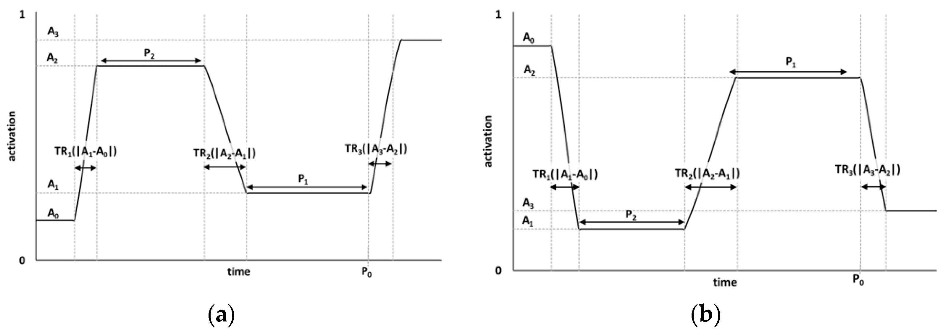
The applied active torque was calculated by multiplying the maximal voluntary torque T at a joint by activating the specific torque representation. Activation was represented by coupled ramp functions that could ramp, according to a quintic polynomial monotonic over the ramping duration, with zero endpoint first and second derivatives, up or down between a minimum activation state of 0 (relaxed) to the maximum activation state of 1 (fully activated). Activation could be of fixed magnitude or transition between a high and low state or vice versa according to the quintic spline functions. The minimum time to ramp fully from relaxed to maximum activation was based on data for trained athletic populations [34], accounting for the non-linearity of the relationship between EMG and torque production [35] and set to 40 ms. In a simulation, the activation level could ramp up or down a maximum of 3 times, e.g., up-down-up (Figure 2a), down-up-down (Figure 2b) or could remain at a constant activation level.
Passive torques were included at the ankle, knee and hip [36] to enable the models to support the range of motion required at the lowest mass centre position of the countermovement jump (extreme joint configuration where it was not possible to accurately measure joint torques on a dynamometer).

2.1. Model Evaluation

The kinematics of a squat and countermovement jump with free arm movement were collected for a 28-year-old male volleyball player, height 1.74 m, mass 79.2 kg using a 16 camera (M2 MCam) Vicon motion analysis system (OMG Plc, Oxford, UK) sampling at 300 Hz [11] along with synchronous measurements of ground-reaction force sampled at 1200 Hz (Kistler instruments Ltd., Hook, UK). Testing procedures were explained to the participant, and written informed consent was obtained in accordance with the guidelines of the [blind for review] ethics committee. The participant undertook four jumps of each, with the maximum height jump of each selected for the evaluation process. In the evaluation process for each jump, the initial conditions were input to the model from the two maximum height jumps recorded performances (Table 1).
The two models were customised to the participant using subject-specific torque parameters determined from isometric and isovelocity measurements at each joint with the participant [11,29,30] (Table 2) and subject-specific segmental inertia parameters determined from anthropometric measurements on the participant [37] (Table 3). SJ and TJ had the same inertia parameters, and the overall strength at each joint was equivalent.
Two objective difference functions expressed as an overall percentage difference were defined that incorporated a combination of kinematic and kinetic variables associated with successful vertical jump performance (Equations (3) and (4)) with differences in linear and angular kinematics, rotation potential at take-off and kinetics combined assuming 1° of rotation was equivalent to 1% for the other variables [38]. The squat jump was matched using Equation (3), while the countermovement jump was matched in two phases, by matching the descent phase using Equation (4) and the ascent phase using Equation (3), (stipulating that the final activation levels of the descent phase be equal to those at the start of the ascent phase). Equation (4) was similar to Equation (3), but did not have the variables at take-off and instead included the vertical reaction force R to ensure a realistic impulse prior to the subsequent matching of the ascent phase. The two-step process for the matching of the countermovement jump with different objective difference functions was necessary, due to the submaximal nature of the descent phase followed by the maximal ascent phase.
( Δ θ M 2 + Δ θ A 2 + Δ θ K 2 + Δ θ H 2 + Δ θ S 2 + Δ θ 0 2 ) 6 + Δ t c 2 + Δ θ t o 2 + Δ Y ˙ t o 2 + Δ H t o 2 5
where ΔθM, ΔθA, ΔθK, ΔθH, ΔθS, Δθ0 represent the RMS differences over the entire simulation for all time steps between simulated and measured joint angles for the MTP, ankle, knee, hip, shoulder and orientation angles, respectively. The variables tc, θto and Δ Y ˙ t o 2 represent the differences between simulation and measured performance expressed as a percentage of measured performance for time of contact, orientation at take-off and vertical velocity at take-off. Hto represents the difference in rotation potential in flight assuming a straight body shape (moment of inertia of 15.5 kg·m2 determined from the inertia data on the participant). Including this measure of rotation in flight within the matching process ensured that matching simulations had an appropriate amount of rotation in flight.
( Δ θ M 2 + Δ θ A 2 + Δ θ K 2 + Δ θ H 2 + Δ θ S 2 + Δ θ 0 2 + Δ R 2 ) 7
where ΔθM, ΔθA, ΔθK, ΔθH, ΔθS, Δθ0 are defined in Equation (3) and ΔR represents the RMS difference between measured and simulated net vertical ground reaction force expressed as a percentage of the peak measured force for this phase of the simulation.
To obtain a matching simulation, a genetic algorithm [39] was used to vary the parameters defining the activation of each torque generator in the model between physiologically realistic bounds to minimise the objective difference function. The squat jump and ascent phase of countermovement jump required a single ramp function (four activation parameters per torque generator (the time at initiation of the final ramp, P0; one ramp duration, TR3; and two activation levels between which the function ramps, A2, A3; Figure 2)). For the countermovement descent, phase a more complex ramp function was required (three ramps consisting of 10 activation parameters per torque generator (the time at initiation of the final ramp, P0; intervals between consecutive ramps at which activation is constant, P1, P2; three ramp durations, TR1, TR2, TR3; and four activation levels between which the function ramps, A0, A1, A2, A3)).
As well as the activation parameters, an additional 12 parameters were varied for the squat jump and ascent phase of the countermovement jump: The torsional spring stiffness, dampening and natural angle (equivalent to natural length in a linear spring) at the MTP joint, the strain of the series elastic component for each torque generator at peak isometric torque and the trunk angular velocity (by 1% from the experimental values). For the descent phase of the countermovement jump, the initial trunk angular velocity was also allowed to vary (by 1% from the experimental values) with the other 11 parameters fixed from the values obtained for the ascent phase of the jump.
This resulted in the following number of parameters being varied for each activity/model: Squat jump (48 parameters (9 × 4 + 12) for SJ and 60 parameters (12 × 4 + 12) for TJ), countermovement descent phase (91 parameters (9 × 10 + 1) for SJ and 121 parameters (12 × 10 + 1) for TJ), countermovement ascent phase (48 parameters (9 × 4 + 12) for SJ and 60 parameters (12 × 4 + 12) for TJ).

3. Results

The two-joint (TJ) model was able to match both the measured squat and countermovement jump performances better than the single-joint (SJ) model (Table 4, Table 5, Table 6 and Table 7).

3.1. Squat Jump

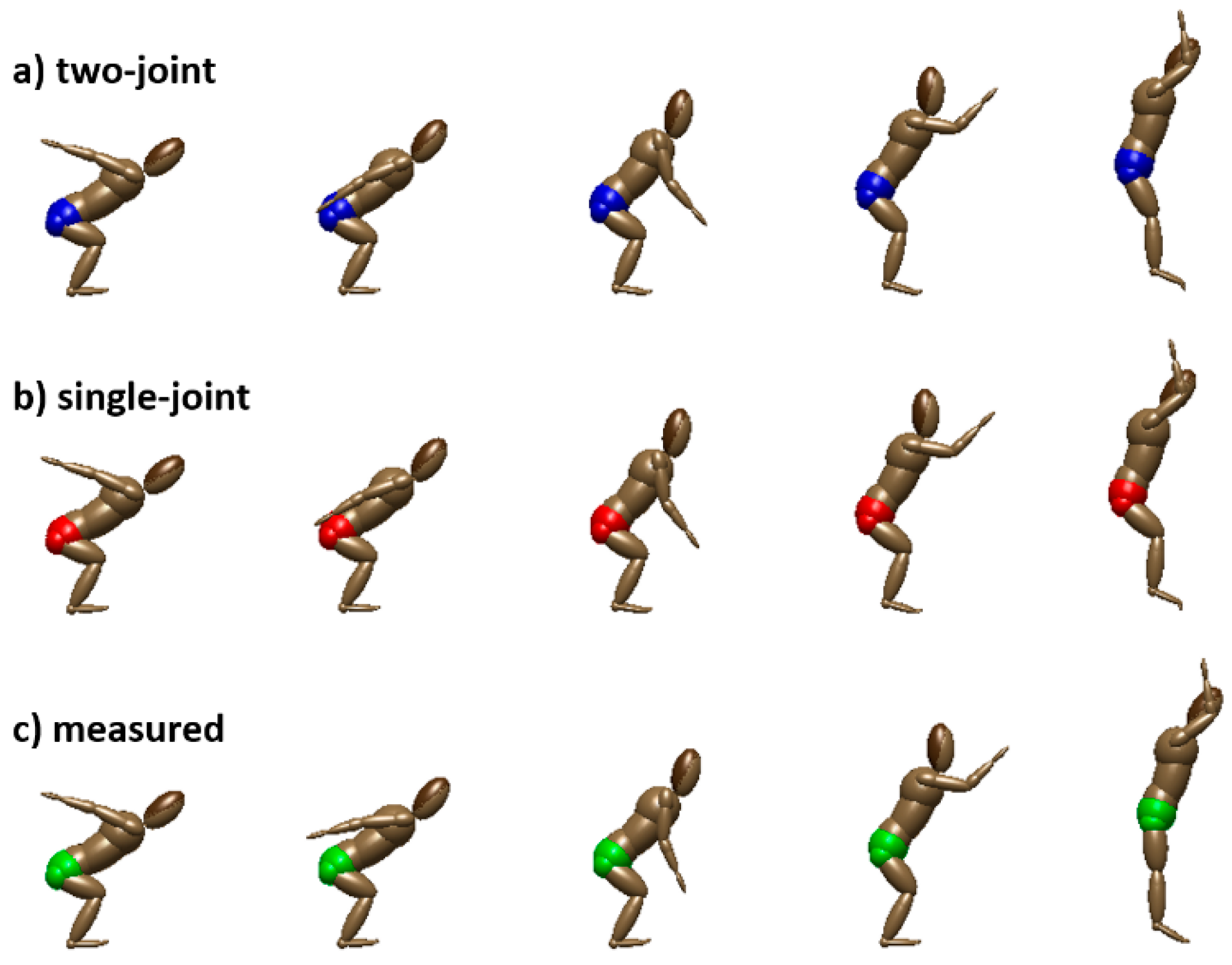
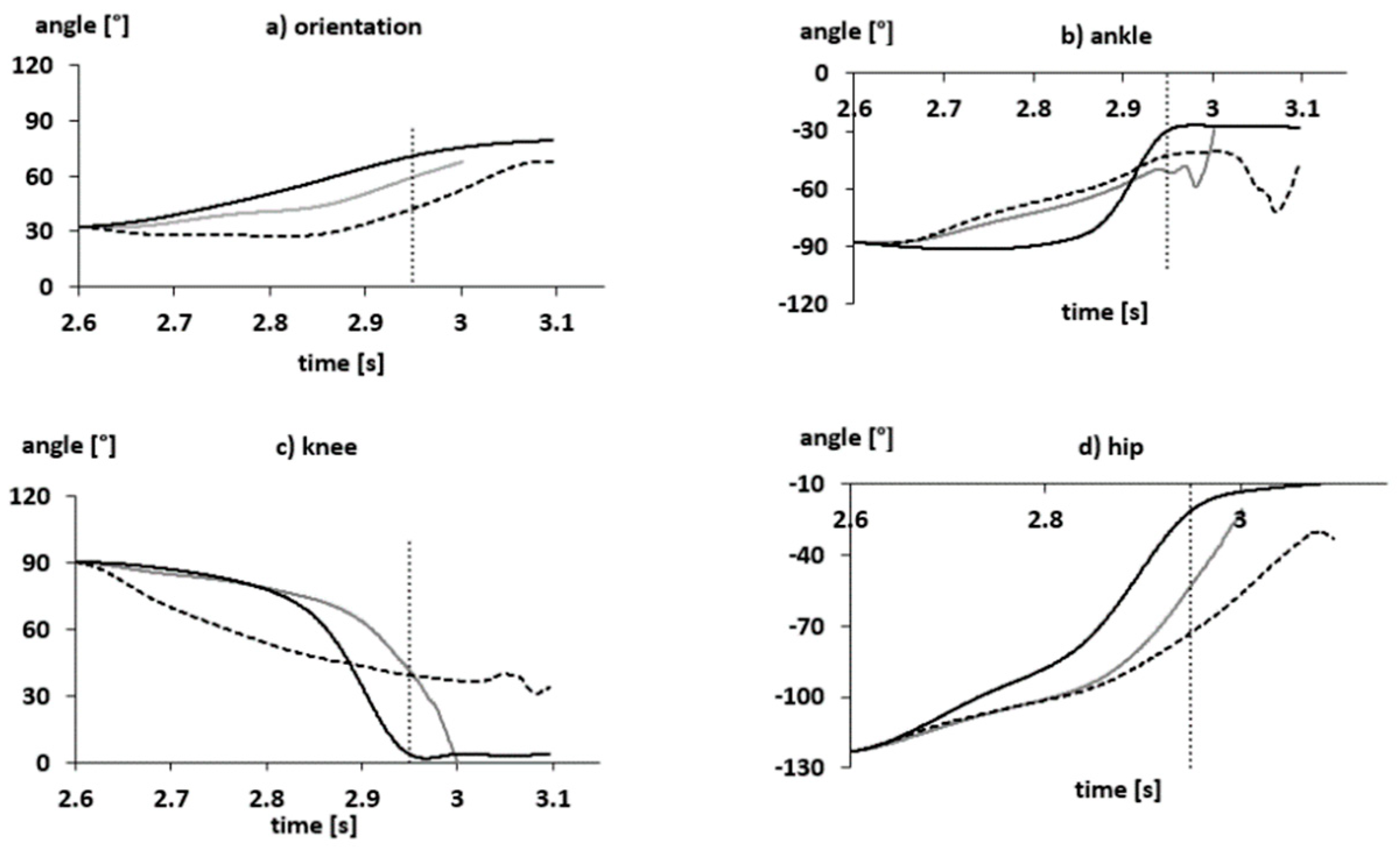
The matching SJ simulation had a 25 cm (10%) smaller jump height than the measured squat jump performance, whilst the matching TJ simulation was 9 cm (6%) smaller than the measured performance. The SJ squat jump simulation achieved a jump height 16 cm smaller (1.28 m) than that of the TJ simulation (1.44 m), where these differences were the sum of smaller vertical displacement both for the contact and flight phases (Table 7). The optimised activation parameters revealed different activation profiles between the torque generators of the SJ and TJ models (Table 4). In general, the SJ simulation adopted uniform activations throughout the simulation by selecting parameters that did not create a ramp in activation. In contrast, the TJ simulation included both ramped activations and sequential activation of the biarticular and monoarticular extensors. Typically, the monoarticular activations would ramp up to full activation much later in the simulation than the biarticular components. The knee flexor activations of the SJ and TJ simulations differed most. The knee flexors and knee extensors of the SJ simulation were relatively submaximal (less than 50%) throughout the simulation, whereas for the TJ simulation there was a ramp to near full activation of the biarticular knee flexor and a uniform full activation of the biarticular knee extensor. There was little difference between the model performances with respect to contact phase duration, orientation at take-off, angular momentum and horizontal velocity. The squat jump simulation models differed more from the measured performance and between each other with respect to joint kinematics and take-off velocity. The TJ model was better than the SJ model at matching the joint kinematics of the participant with differences from measured kinematics of 13.4° and 17.0°, respectively (Table 7, Figure 3 and Figure 4). Considering the kinematics of joints which differed in the representation of the torques between the SJ and TJ simulations, the ankle joints differed most obviously from the measured performance. In both simulations, the ankle plantar flexed until approximately 0.1 s prior to take-off, which coincided with the largest joint angle changes at the knee and hip and appeared to be required to manage the large proximal joint torques by placing the ankle joint in a stronger position (Figure 3 and Figure 4). For the knee and hip joints, the TJ model performed better by more closely matching the larger velocities of the measured performance, but most importantly, in achieving greater joint extension. At the ankle, the SJ model had 10° less extension at take-off than the measured performance, whilst this was 1° for the TJ model. At the knee, the SJ model had 49° less extension at take-off than the measured performance, whilst this was 20° for the TJ model. At the hip, the SJ model had 46° less extension at take-off than the measured performance, whilst this was 24° for the TJ model (Figure 3 and Figure 4).

3.2. Countermovement Jump

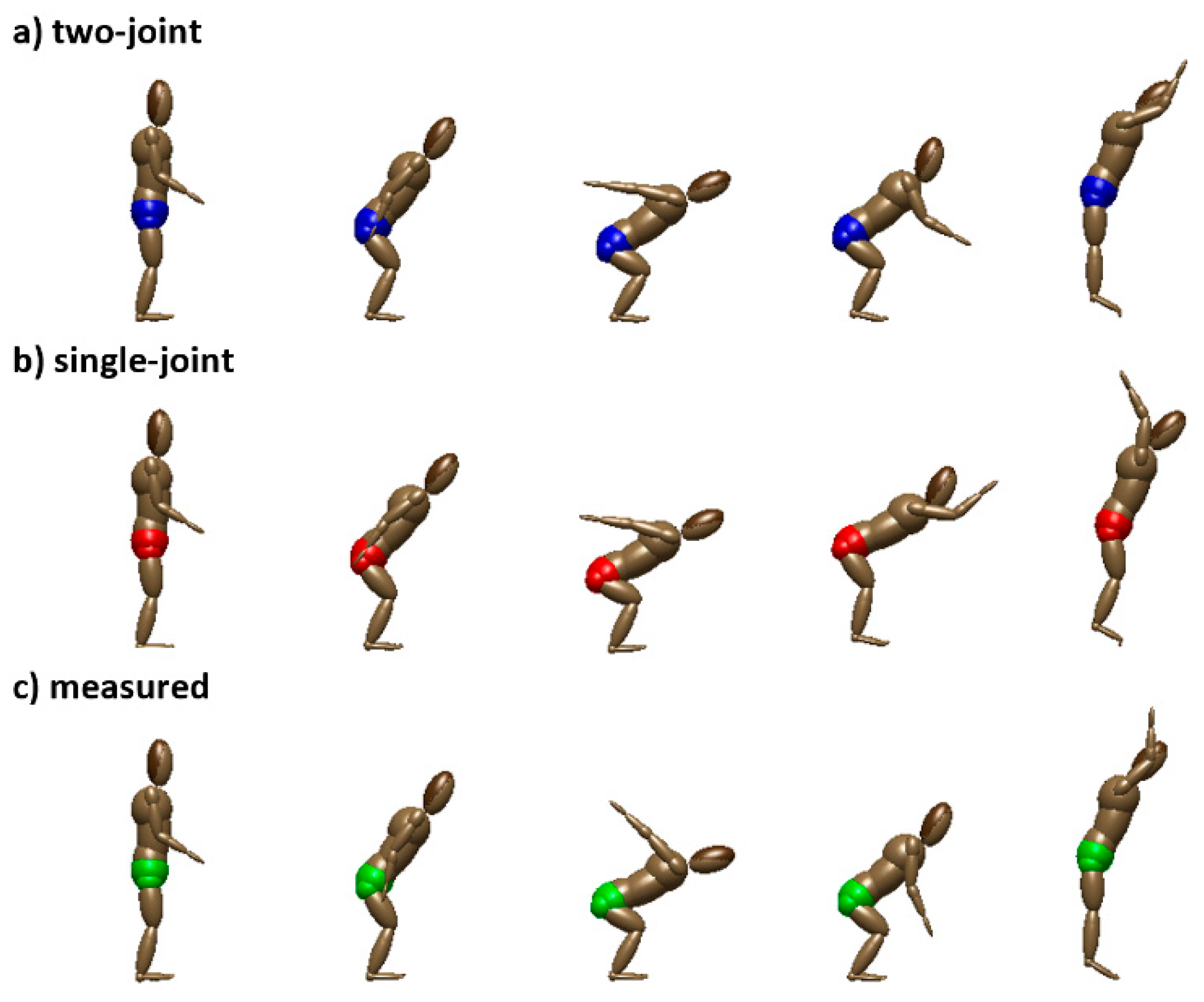
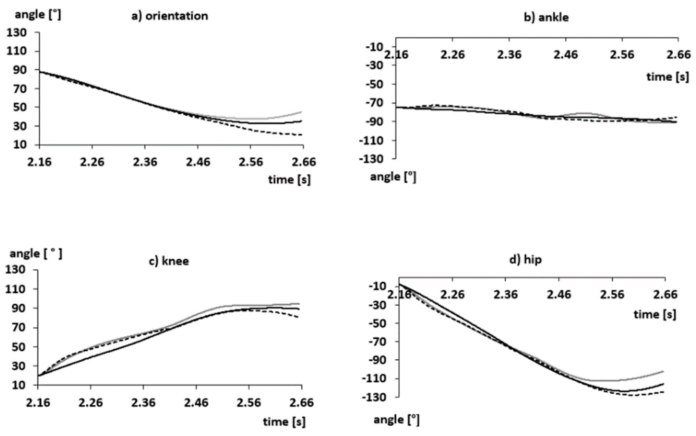
The descent phase of the countermovement jump was matched with similar accuracy by both the SJ and TJ simulations, with no discernible differences in the techniques (9° differences between measured performance and matched simulations; Table 7, Figure 5 and Figure 6). The results for the ascent phase of the countermovement jump highlighted similar characteristics for between-model differences as those of the squat jump, but with differences of typically larger magnitude. The overall difference between the SJ model and participant performance was 24.3%, and for the TJ model, 10.1% (Table 7). The TJ model closely matched the measured jump, with a peak mass centre height of 1.50 m, 6 cm smaller than the measured performance. The SJ model achieved a peak jump height of 1.38 m, 18 cm smaller than the measured performance, with most of this difference associated with the flight phase (14 cm), and therefore, the take-off velocity, rather than the mass centre height at take-off. The larger differences for the SJ model relate to a poorer capacity to match the measured joint kinematics at all joints. The optimised activation parameters of the full countermovement jump highlighted a requirement by both the SJ and TJ simulations for fewer than two ramps during the descent phase of the countermovement, and in the case of the ascent phase, often a single ramp was not required in the SJ simulation (Table 5 and Table 6). In the case of the SJ simulation, during the ascent phase, either a uniform activation or a small ramp in activation was employed. The TJ simulation again demonstrated sequential timing of ramps for the biarticular and monoarticular plantar flexors and knee extensors. The TJ model was able to demonstrate different approaches to the application of the monoarticular and biarticular knee flexors, with a large activation of the biarticular component (also a hip extensor) and a small submaximal activation of the monoarticular component (less than 40% activation). The SJ simulation is incapable of having both large and submaximal activations of the knee flexors and so had a uniform large, but not maximal, knee flexor activation throughout much of the simulation. Hip flexor and hip extensor activation profiles were broadly similar for the SJ and TJ simulations, but despite the availability of multiple ramps, the SJ simulation employed far fewer than those available and adopted broadly single ramp profiles across the full descent and ascent phase. The duration of the simulation was markedly longer for the SJ model than the TJ model (SJ model 0.5 s, TJ model 0.4 s, measured 0.35 s), which enabled the SJ simulation to have a proportionally higher mass centre height at take-off. The ankle joint kinematics for both the SJ and TJ models had similar characteristics to those of the squat jump. At the knee and hip joints, there was a clear similarity between the kinematics adopted by the TJ model and the measured performance, but the SJ model adopted a very different technique at the knee and achieved much smaller velocities at the hip (Figure 5, Figure 6 and Figure 7). In general, the errors in joint kinematics for the ascent phase differed by an additional 8–10° compared to the TJ model. As for the squat jump, the SJ countermovement jump achieved a smaller lower-limb joint extension than the TJ equivalent (Figure 7). At the ankle, the SJ model had 20° less extension at take-off than the measured performance, whilst this was 1° for the TJ model. At the knee, the SJ model had 30° less extension at take-off than the measured performance, whilst this was 6° for the TJ model. At the hip, the SJ model had 24° less extension at take-off than the measured performance, whilst this was 7° for the TJ model.

3.3. Work Done

Concentric and eccentric joint work was calculated for each torque generator and summed to provide the net work done by each component at a joint. For the squat jump (Table 8), the net ankle work was similar between SJ and TJ models, with one third of the plantar flexor work for the TJ model coming from the biarticular component. At the knee joint, the net knee work was similar between SJ and TJ models, although there was substantial TJ biarticular knee flexor work that was negated by predominantly monoarticular knee extensor work. At the hip joint, there was 36% more work done by the TJ hip extensors, of which 63% was from the biarticular knee flexor-hip extensor torque generators, which performed as much work as the SJ hip extensors. For the countermovement jump (Table 9), the work calculations represent both descent and ascent phases. At the ankle joint, the SJ model produced 32% more net ankle work than the TJ simulation model. The TJ simulation had a 68% contribution to plantar flexor work from the biarticular component. A similar scenario existed for the knee work in the countermovement jump as for the squat jump, with small net knee joint work, but a large contribution at the knee from the biarticular knee flexor which was negated by the monoarticular extensor. With respect to the hip joint work, the TJ simulation performed 21% more work than the SJ simulation, and most of this contribution was from the biarticular knee flexor-hip extensor.
By way of illustrating the nature of the differences in work and potential mechanical advantage from moment arms, the mean contractile component velocity for the plantar flexors and hip extensors, as a percentage of the joint velocity, was calculated for the entire simulation (Table 10). When examining the biarticular plantar flexor contractile component velocity for the squat jump and the biarticular hip extensor contractile component velocity for the squat and countermovement jumps, the biarticular velocities were substantially less than the joint velocity and their monoarticular and single-joint equivalents at 66%, 58% and 25% of joint velocity, respectively. According to the Hill hyperbola (force-velocity relationship), this would place them at a torque generating advantage. In contrast, the monoarticular and SJ torque generators had contractile component velocities that more closely reflected their joint velocities. In the case of the TJ squat jump model and when examining the full simulation, the biarticular component had an average contractile component velocity that was larger than the monoarticular equivalent and SJ version. This was because it started with a much lower activation level that ramped up continuously throughout the simulation, causing the series elastic component to be stretched and the contractile component to shorten, as compared to the monoarticular component, which had a constant activation of approximately 50% for the first 0.25 s, and therefore, had an almost constant series elastic component length. For the final 130 ms of the jump, the same situation occurs as for other jumps, with the biarticular component experiencing contractile component velocities 74% of the joint velocity instead of the monoarticular or single-joint equivalents that were 103% and 95%, respectively.

4. Discussion

The aim of this study was to investigate whether the incorporation of TJ torque generators in addition to SJ torque generators in a computer simulation model improves accuracy when simulating maximal squat jumps and countermovement jumps. It was found that the use of subject-specific TJ representations of lower-limb joint torques rather than SJ representations resulted in smaller differences between the simulation model and measured performances for both squat and countermovement jumps. The magnitude of the differences was small for the submaximal descent of the countermovement and large for movements requiring larger joint torques and a requirement for large joint velocities (e.g., Figure 6 and Figure 7).
The SJ model was unable to match closely the work or maximal joint velocities of measured squat or countermovement jumps, something achieved with better accuracy by a TJ model. It has been proposed that the monoarticular assumption might result in a model with insufficient ability to generate work when it must achieve this throughout the simulation [31]. In this study, the TJ model increased the mechanical energy throughout the simulation by 659 J (squat) and 457 J (countermovement), while the SJ model increased the mechanical energy by 557 J (squat) and 372 J (countermovement). This highlights the dual insufficiency of an SJ model to perform sufficient work compared to a TJ model, along with an inability to match high velocity joint kinematics. The results of this investigation have demonstrated performance differences for the squat and countermovement jump simulations, when employing SJ or TJ torque generators. The differences were associated with the ascent phase of both jumps, but not with the submaximal descent phase of the countermovement jump (Table 7). The overall difference between simulation and matched performances were smaller for SJ (10%) and TJ (6%) simulations of squat jumping than for the ascent phase of the countermovement jump (SJ 24% and TJ 10%). The predominant contributors to these differences were joint kinematics and vertical velocity at take-off. Previous torque and individual muscle-driven simulations of jumping, with and without a countermovement, have placed less emphasis on matching the kinematics throughout the jump. Instead, they have adopted objective functions which require the simulation to achieve specific kinematic values at critical instants, e.g., specific joint configurations such as greatest drop depth, and take-off characteristics [31]. As a consequence, the joint velocity characteristics of the model and coordination between joints has been included very simplistically in the overall evaluation. The present study offers some wider insight into the capacity of each joint to match the technical requirements for jumping.
Submaximal activities such as the descent phase of a countermovement jump may be modelled with similar accuracy by SJ and TJ simulation models, with large differences only arising for maximal jumping activity in the ascent phase. When simulating the submaximal descent phase of a countermovement jump, both simulation approaches achieved comparable agreement with measured kinematics and kinetics. The agreement was very good, and it is likely that the capacity of both models to generate work and provide adequate degrees of freedom to provide fine control of slow movements is good. However, the maximal effort of the squat jump and ascent phase of the countermovement jump highlighted much larger differences in the capacity of an SJ or TJ model to match measured kinematics. Overall a TJ approach better matched the performance outcome, in terms of the height attained by the mass centre, and the technique employed. A clear advantage for the TJ model was found by examining the work generated at each joint (Table 8 and Table 9). For both the squat and countermovement jump, the TJ models performed more net plantar flexor work at both joints than the SJ model, which largely explains the closer matching of joint kinematics, and especially those approaching take-off. The direction and magnitude of work performed at the knee joint differed between SJ and TJ models. Net joint moments at the knee for the countermovement jump, differed between models by approximately 20 J. The SJ model performed a small net negative work (knee flexion), whilst the TJ performed a small net positive work (knee extension). This relationship was reversed for the squat jump. In the case of the squat jump, the constituents towards the net joint work warrant some mention. The magnitude of work done by the TJ model for knee flexion and knee extension was approximately 2.53 J·kg1 larger than for the SJ model. The activation profiles of the SJ knee extensors and flexors had small activations of approximately 20%, whereas, for the TJ model, there were small activations of monoarticular knee flexors and near-maximal activation of the biarticular knee flexors (hip extensors), monoarticular and biarticular knee extensors. In this case, the large positive work of the knee extensors acted as a solution to overcoming the negative work of the knee flexors, thus allowing work from the biarticular knee flexors to generate extensor work at the hip. The mechanisms, which enabled the TJ simulation to better match performance, appear to relate to both torque generation and motor control. Firstly, examining the shortening velocities of the biarticular torque generators alongside their monoarticular equivalents, it is evident that biarticular components are shortening at relatively slower velocities than their monoarticular equivalents because of concurrent TJ kinematics. Muscle force-velocity properties [19,40] predispose that for slower velocities of shortening, the contractile component can exert much larger forces. In the case of the TJ models in this study, by virtue of having favourable moment arms at two joints, the actions of concurrent ankle plantar flexion, knee-extension and hip extension enable the biarticular plantar flexors and biarticular knee flexors to have smaller shortening velocities than the monoarticular components, as such shortening slower whilst exerting favourable torques at proximal joints.
The SJ model relative to the TJ model was much less effective at matching the countermovement jump performance than the squat jump (Table 7). The joint velocities of the countermovement ascent phase were much larger than for the squat jump, and this is likely to be a factor differentiating the results of the countermovement jump from the squat jump (Table 7). The concurrent extension of two joints about which biarticular muscles act allows the biarticular shortening velocity to be smaller than for a comparable joint where the torque generator velocity is governed only by one joint’s kinematics, as is the case for a monoarticular component or for a similar SJ torque representation. The force-velocity characteristics of muscle mean that for an equivalent length, but a slower shortening velocity, a muscle can exert greater force. The effect of including TJ representations of torque at a joint means that some proportion of the torque generating capacity is affected less by fast joint kinematics, and therefore, capable of performing more work than if it were included as a component of an SJ torque generator. The mean shortening velocities of SJ or monoarticular components were predominantly larger than biarticular components. When examining the proportion of work generated by the biarticular components, it was evident that the TJ simulation benefitted from an increased torque generating capacity offered by slower shortening velocities, and larger torques could be exerted up to take-off because of the relatively slower shortening velocity. The degrees of freedom of the model and multiple components included in the simulation objective function meant that the SJ countermovement simulation identified a novel solution for improving the overall matching of the measured performance in the absence of the capacity to generate a large take-off velocity. The SJ simulation model maximised the height achieved by the mass centre by lengthening the contact period and more fully extending the joints of the lower limbs (Table 7). However, this solution resulted in excessive rotation and larger horizontal mass centre velocities (Figure 5).
Some discrete variables included in the objective functions (Equations (3) and (4)) may be overly weighted, and as such, heavily influence the matching process or may be unnecessary for the purposes of matching performances. The SJ and TJ simulations were effective for both jumps at matching contact time, angular momentum and orientation at take-off. These components of the objective function were always smaller than others, irrespective of model or jump type. It is possible that the weighting of these components is too large in the model objective function such that they draw the search more towards matching these variables, or that they are too easy to achieve by virtue of the available degrees of freedom in either the SJ or TJ model, and therefore, are irrelevant when differentiating model performance. It is common in the jumping simulation literature to include predominantly simple objective functions such as to match or maximise jump height [13,41,42,43]. The latter implies that the aim is simply to achieve the largest jump height with disregard for any criterion associated with acquiring a solution that ensures realistic landing conditions. Authors attempting to match more comprehensive objective functions, such as the authors of [44], who matched net joint moments, the authors of [45], who matched kinematics and activation characteristics, and the authors of [1], who matched a combination of kinematic criteria, including angular momentum at take-off, have typically not identified empirical evidence that supports the weighting of components in their objective function. In the present study, when attempting to match the descent and ascent phases together, the inclusion of outcome measures such as take-off velocity or jump height incurred large errors in matching the descent phase and ultimately produced very large differences between modelled and measured kinematics. It is clear, that there is a transition between the importance placed on aspects of performance such as stability in the initial descent and maximum vertical velocity throughout the ascent phase. What is not clear is how this transition is manifested and whether there is a realistic method for modelling the transition between objective function variable weightings, which can better match the demands of the performance. To enable the future matching of a countermovement jump using a single objective function from the initial standing position to take-off, necessitates a better understanding of the weighting of components of the objective function as the simulation transfers from submaximal to maximal activity. One such solution is to use a variety of experimental interventions to manipulate the demands of vertical jumping, for example, placing different emphasis on stability and jump height and then using data reduction and clustering methods, such as principle component analysis (PCA) and discriminant function analysis (DFA), to calculate variable weightings for an objective function [46].
The use of biarticular (TJ) torque generators in simulations of jumping goes some way to bridging the gap between the capability of torque-driven simulations, which have typically answered questions associated with whole-body performance, and those of individual muscle models, which have tackled questions associated with neuromuscular control and individual muscle properties. A TJ simulation provides an additional illustration of the neuromuscular system by providing a synergistic description of monoarticular and biarticular components. Using a TJ simulation, it is now possible to investigate the general role of biarticular torque generators by combining the evaluation of technique and EMG. The number of available activation parameters for a TJ simulation is larger than that for SJ, however it should be noted that were the limitation of the SJ simulation that of a control limitation, it might have been expected that the simulation would exploit all the activation parameters available to it for ramping up and down the activations. More broadly, the SJ simulation did not use all the available ramps in activation and fewer than the TJ simulation, suggesting that the predominant limitation of the SJ model relates to strength.
In this study, a single participant design was used, and this could be considered to be a limitation of the study as the effect of different inertias and strengths have not been considered. However, using a mechanics-based computer simulation model, the inertias and strength parameters used have much less influence on model performance than the activity to be modelled. Furthermore, although the model, including TJ representations, has more parameters to vary compared with the SJ version, the overall strength at each joint for both models was equivalent. This limits any advantage of additional parameters, and could indeed lead to worse performance if such in-built relationships were not of advantage for the movement under consideration. The objective difference functions, Equations (3) and (4), assume that a 1° difference in an angle change was equivalent to a 1% difference in time of contact, the vertical velocity at take-off or vertical ground reaction force. This is a reasonable assumption that has been successfully used to evaluate previously developed simulation models [38], giving a balanced measure of how well the model can match an actual performance across multiple criteria.
In conclusion, the use of subject-specific TJ representations of lower-limb joint torques rather than SJ representations, results in smaller differences between simulations and measured performances for both squat and countermovement jumps (examples of activities that start with minimal initial energy but require maximal effort). The magnitude of the difference between simulations and measured performances are small for the submaximal, weight assisted, slow speed downward countermovement and large for movements requiring larger joint torques and a requirement for large joint velocities. The outcome measure of jump height alone indicates a clear improvement in model accuracy when utilising a TJ representation. However, simple SJ models are equally effective at matching submaximal aspects of the countermovement jump. Overall a TJ torque generator representation is likely to be more appropriate for simulating dynamic tasks requiring large joint torques and near-maximal joint velocities.

Author Contributions

Conceptualization, all authors; writing—original draft preparation, M.G.C.L.; writing—review and editing, all authors; supervision, M.R.Y. and M.A.K. All authors have read and agreed to the published version of the manuscript.

Funding

This research received no external funding.

Institutional Review Board Statement

The study was conducted according to the guidelines of the Declaration of Helsinki and approved by the Ethics Committee of Loughborough University (protocol G01-P1, 2007).

Informed Consent Statement

Informed consent was obtained from all subjects involved in the study.

Data Availability Statement

The data presented in this study are available on request from the corresponding author. The data are not publicly available due to privacy.

Conflicts of Interest

The authors declare no conflict of interest.

References

  1. King, M.A.; Yeadon, M.R. Maximising somersault rotation in tumbling. J. Biomech. 2004, 37. [Google Scholar] [CrossRef] [PubMed] [Green Version]
  2. Wilson, C.; Yeadon, M.R.; King, M.A. Considerations that affect optimised simulation in a running jump for height. J. Biomech. 2007, 40. [Google Scholar] [CrossRef] [Green Version]
  3. Allen, S.J.; King, M.A.; Yeadon, M.R. Is a single or double arm technique more advantageous in triple jumping? J. Biomech. 2010, 43. [Google Scholar] [CrossRef] [Green Version]
  4. Hiley, M.J.; Jackson, M.I.; Yeadon, M.R. Optimal technique for maximal forward rotating vaults in men’s gymnastics. Hum. Mov. Sci. 2015, 42, 117–131. [Google Scholar] [CrossRef] [PubMed] [Green Version]
  5. Lloyd, D.G.; Besier, T.F. An EMG-driven musculoskeletal model to estimate muscle forces and knee joint moments in vivo. J. Biomech. 2003, 36, 765–776. [Google Scholar] [CrossRef]
  6. Yeadon, M.R.; King, M.A. Computer simulation modelling in sport. In Biomechanical Evaluation of Movement in Sport and Exercise: BASES Guidelines; Payton, C.J., Bartlett, R.M., Eds.; Routledge: London, UK, 2018; pp. 176–205. [Google Scholar]
  7. King, M.A.; Yeadon, M.R. Advances in the development of whole body computer simulation modelling of sports technique. Mov. Sport. Sci. Sci. Mot. 2015, 43. [Google Scholar] [CrossRef] [Green Version]
  8. Wilson, C.; King, M.A.; Yeadon, M.R. The effects of initial conditions and takeoff technique on running jumps for height and distance. J. Biomech. 2011, 44. [Google Scholar] [CrossRef] [PubMed] [Green Version]
  9. Allen, S.J.; King, M.A.; Yeadon, M.R. Optimisation of phase ratio in the triple jump using computer simulation. Hum. Mov. Sci. 2016, 46. [Google Scholar] [CrossRef] [Green Version]
  10. King, M.A.; Kong, P.W.; Yeadon, M.R. Maximising forward somersault rotation in springboard diving. J. Biomech. 2019, 85. [Google Scholar] [CrossRef] [Green Version]
  11. Lewis, M.G.C.; Yeadon, M.R.; King, M.A. The effect of accounting for biarticularity in hip flexor and hip extensor joint torque representations. Hum. Mov. Sci. 2017. [Google Scholar] [CrossRef] [PubMed]
  12. Ashby, B.M.; Delp, S.L. Optimal control simulations reveal mechanisms by which arm movement improves standing long jump performance. J. Biomech. 2006, 39, 1726–1734. [Google Scholar] [CrossRef]
  13. Cheng, K.B.; Wang, C.-H.; Chen, H.-C.; Wu, C.-D.; Chiu, H.-T. The mechanisms that enable arm motion to enhance vertical jump performance—A simulation study. J. Biomech. 2008, 41, 1847–1854. [Google Scholar] [CrossRef] [PubMed]
  14. Selbie, W.S.; Caldwell, G.E. A simulation study of vertical jumping from different starting postures. J. Biomech. 1996, 29, 1137–1146. [Google Scholar] [CrossRef]
  15. Yeadon, M.R.; King, M.A.; Wilson, C. Modelling the maximum voluntary joint torque/angular velocity relationship in human movement. J. Biomech. 2006, 39. [Google Scholar] [CrossRef] [PubMed] [Green Version]
  16. Forrester, S.E.; Yeadon, M.R.; King, M.A.; Pain, M.T.G. Comparing different approaches for determining joint torque parameters from isovelocity dynamometer measurements. J. Biomech. 2011, 44. [Google Scholar] [CrossRef] [Green Version]
  17. Gordon, A.M.; Huxley, A.F.; Julian, F.J. The variation in isometric tension with sarcomere length in vertebrate muscle fibres. J. Physiol. 1966, 184, 170–192. [Google Scholar] [CrossRef]
  18. Fenn, W.O.; Marsh, B.S. Muscular force at different speeds of shortening. J. Physiol. 1935, 85, 277–297. [Google Scholar] [CrossRef]
  19. Hill, A.V. The heat of shortening and the dynamic constants of muscle. Proc. R. Soc. Lond. Ser. B Biol. Sci. 1938, 126, 136–195. [Google Scholar] [CrossRef]
  20. Katz, B. The relation between force and speed in muscular contraction. J. Physiol. 1939, 96, 45–64. [Google Scholar] [CrossRef] [PubMed]
  21. van Soest, A.J.; Schwab, A.L.; Bobbert, M.F.; van Ingen Schenau, G.J. The influence of the biarticularity of the gastrocnemius muscle on vertical-jumping achievement. J. Biomech. 1993, 26, 1–8. [Google Scholar] [CrossRef]
  22. Böhm, H.; Cole, G.K.; Brüggemann, G.-P.; Ruder, H. Contribution of muscle series elasticity to maximum performance in drop jumping. J. Appl. Biomech. 2006, 22, 3–13. [Google Scholar] [CrossRef] [PubMed]
  23. Bisseling, R.W.; Hof, A.L. Handling of impact forces in inverse dynamics. J. Biomech. 2006, 39, 2438–2444. [Google Scholar] [CrossRef]
  24. Hof, A.L. The force resulting from the action of mono- and biarticular muscles in a limb. J. Biomech. 2001, 34, 1085–1089. [Google Scholar] [CrossRef] [Green Version]
  25. Jones, S.L.; Caldwell, G.E. Mono- and Biarticular Muscle Activity during Jumping in Different Directions. J. Appl. Biomech. 2003, 19, 205–222. [Google Scholar] [CrossRef] [Green Version]
  26. Kuo, A.D. The action of two-joint muscles: The legacy of W.P. Lombard, in Classics in Movement Science. In Classics in Movement Science; Latash, M.L., Zatsiorsky, V.M., Eds.; Human Kinetics: Champaign, IL, USA, 2001; pp. 289–315. [Google Scholar]
  27. Doorenbosch, C.A.M.; van Ingen Schenau, G.J. The role of mono- and bi-articular muscles during contact control leg tasks in man. Hum. Mov. Sci. 1995, 14, 279–300. [Google Scholar] [CrossRef]
  28. Shinohara, M.; Yoshitake, Y.; Kouzaki, M.; Fukunaga, T. The medial gastrocnemius muscle attenuates force fluctuations during plantar flexion. Exp. Brain Res. 2006, 169, 15–23. [Google Scholar] [CrossRef]
  29. King, M.A.; Lewis, M.G.C.; Yeadon, M.R. Is it necessary to include biarticular effects within joint torque representations of knee flexion and knee extension? Int. J. Multiscale Comput. Eng. 2012, 10. [Google Scholar] [CrossRef]
  30. Lewis, M.G.C.; King, M.A.; Yeadon, M.R.; Conceição, F. Are joint torque models limited by an assumption of monoarticularity? J. Appl. Biomech. 2012, 28, 520–529. [Google Scholar] [CrossRef] [Green Version]
  31. King, M.A.; Wilson, C.; Yeadon, M.R. Evaluation of a torque-driven model of jumping for height. J. Appl. Biomech. 2006, 22, 264–274. [Google Scholar] [CrossRef] [Green Version]
  32. Kane, T.R.; Levinson, D.A. Dynamics, Theory and Applications; McGraw Hill: New York, NY, USA, 1985; ISBN 0-07-037846-0. [Google Scholar]
  33. Yeadon, M.R.; Kong, P.W.; King, M.A. Parameter determination for a computer simulation model of a diver and a springboard. J. Appl. Biomech. 2006, 22, 167–176. [Google Scholar] [CrossRef] [PubMed] [Green Version]
  34. Tillin, N.A.; Jimenez-Reyes, P.; Pain, M.T.G.; Folland, J.P. Neuromuscular Performance of Explosive Power Athletes versus Untrained Individuals. Med. Sci. Sport. Exerc. 2010, 42, 781–790. [Google Scholar] [CrossRef] [Green Version]
  35. Kooistra, R.D.; de Ruiter, C.J.; de Haan, A. Conventionally assessed voluntary activation does not represent relative voluntary torque production. Eur. J. Appl. Physiol. 2007, 100, 309–320. [Google Scholar] [CrossRef] [Green Version]
  36. Riener, R.; Edrich, T. Identification of passive elastic joint moments in the lower extremities. J. Biomech. 1999, 32, 539–544. [Google Scholar] [CrossRef]
  37. Yeadon, M.R. The simulation of aerial movement—II. A mathematical inertia model of the human body. J. Biomech. 1990, 23, 67–74. [Google Scholar] [CrossRef] [Green Version]
  38. Yeadon, M.R.; King, M.A. Evaluation of a torque-driven simulation model of tumbling. J. Appl. Biomech. 2002, 18, 195–206. [Google Scholar] [CrossRef] [Green Version]
  39. Carroll, D.L. Genetic algorithms and optimizing chemical oxygen-iodine lasers. Dev. Theor. Appl. Mech. 1996, 18, 411–424. [Google Scholar]
  40. Edman, K.A. Double-hyperbolic force-velocity relation in frog muscle fibres. J. Physiol. 1988, 404, 301–321. [Google Scholar] [CrossRef]
  41. Pandy, M.G.; Zajac, F.E.; Sim, E.; Levine, W.S. An optimal control model for maximum-height human jumping. J. Biomech. 1990, 23, 1185–1198. [Google Scholar] [CrossRef]
  42. Anderson, F.C.; Pandy, M.G. A dynamic optimization solution for vertical jumping in three dimensions. Comput. Methods Biomech. Biomed. Engin. 1999, 2, 201–231. [Google Scholar] [CrossRef]
  43. Nagano, A.; Komura, T.; Fukashiro, S.; Himeno, R. Force, work and power output of lower limb muscles during human maximal-effort countermovement jumping. J. Electromyogr. Kinesiol. 2005, 15, 367–376. [Google Scholar] [CrossRef] [PubMed]
  44. Bobbert, M.F.; Gerritsen, K.G.M.; Litjens, M.C.A.; Van Soest, A.J. Why is countermovement jump height greater than squat jump height? Med. Sci. Sports Exerc. 1996, 28, 1402–1412. [Google Scholar] [CrossRef] [PubMed]
  45. Spägele, T.; Kistner, A.; Gollhofer, A. Modelling, simulation and optimisation of a human vertical jump. J. Biomech. 1999, 32, 521–530. [Google Scholar] [CrossRef]
  46. Bisele, M.; Bencsik, M.; Lewis, M.G.C.; Barnett, C.T. Optimisation of a machine learning algorithm in human locomotion using principal component and discriminant function analyses. PLoS ONE 2017, 12, e0183990. [Google Scholar] [CrossRef] [PubMed] [Green Version]
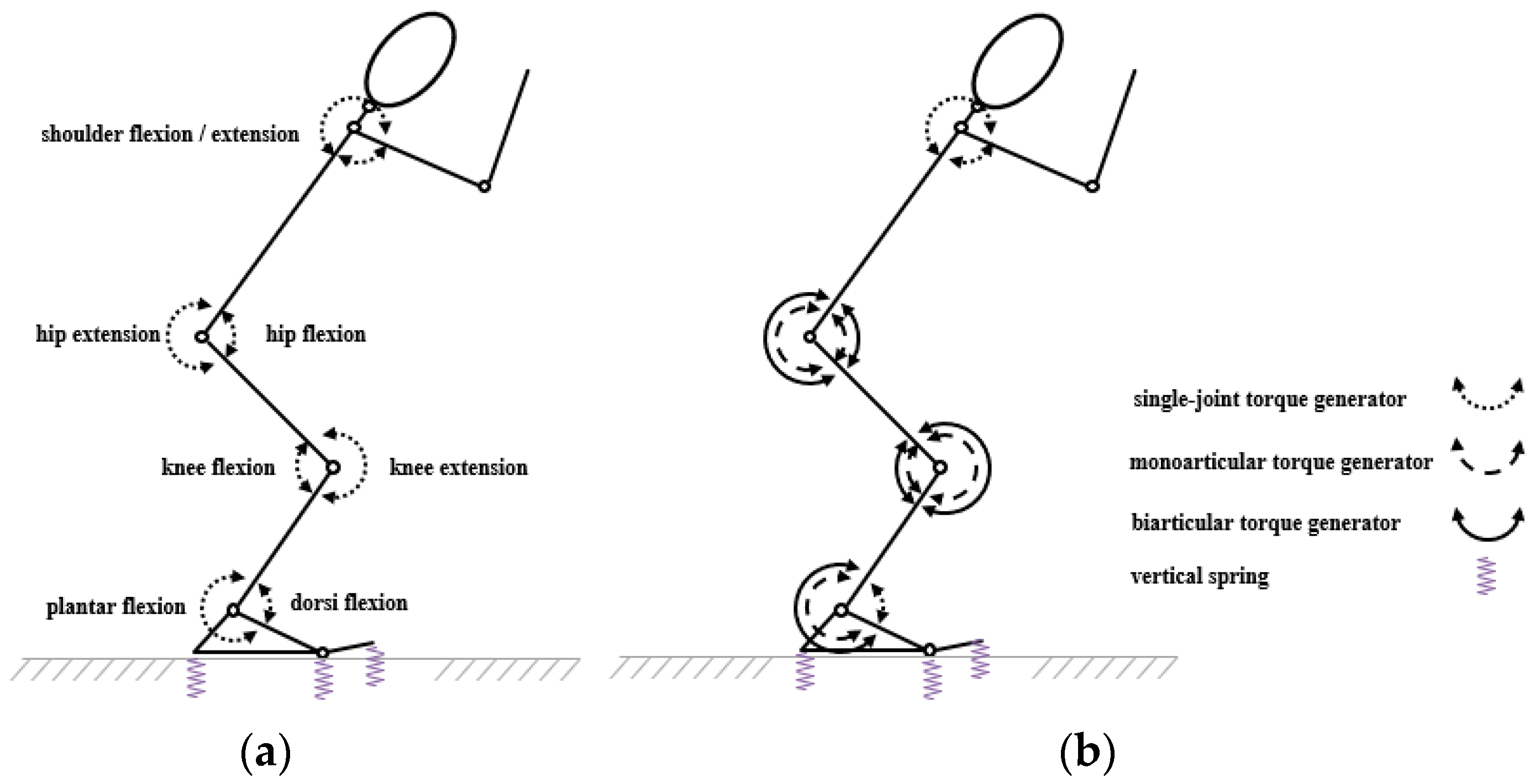
Figure 1. Eight-segment simulation models (a) single-joint (SJ) and (b) two-joint (TJ).
Applsci 11 03852 g001
Figure 2. Two typical examples of possible activation functions: (a) Up-down-up, (b) down-up-down. The input parameters are composed of the duration required for full activation from relaxed (TR#), time when final ramp commences (P0), interval or plateau between consecutive ramps (P1–2), activation level at start and end of ramp (A0–3). The timings of all ramp functions and periods of constant activation, are assigned relative to the onset of the final ramp.
Applsci 11 03852 g002
Figure 3. Graphical comparison of the squat jump simulations at equal time intervals from initial conditions to take-off; (a) TJ, (b) SJ and (c) measured performance.
Applsci 11 03852 g003
Figure 4. Squat jump; SJ (dashed black line), TJ (solid grey line), measured (solid black line); (a) orientation, (b) ankle, (c) knee, (d) hip angles.
Applsci 11 03852 g004
Figure 5. Graphical comparison of the countermovement jump simulations at equal time intervals from initial conditions to take-off; TJ, SJ and measured performance.
Applsci 11 03852 g005
Figure 6. Countermovement jump descent; SJ (dashed black line), TJ (solid grey line), measured (solid black line); (a) orientation, (b) ankle, (c) knee, (d) hip.
Applsci 11 03852 g006
Figure 7. Countermovement jump ascent; SJ (dashed black line), TJ (solid grey line), measured (solid black line); (a) orientation, (b) ankle, (c) knee, (d) hip.
Applsci 11 03852 g007
Table 1. The initial kinematics for the simulations of the squat jump and the countermovement jump (where full extension refers to the anatomical position).
Angle and Definition+ve Angular VelocitySquat JumpCountermovement Jump
Angle Angular VelocityAngleAngular Velocity
[°][°·s−1][°][°·s−1]
trunk angle from horizontalanti-clockwise56388−107
MTP angle from full extensionflexion43043−1
ankle angle from full extensionplantar flexion−90−4−75−43
knee angle from full extensionflexion96−1720177
hip angle from full extensionextension−1235−8−235
shoulder angle from full extensionflexion−609711104
elbow angle from full extensionflexion20−135071
neck angle from full extensionflexion−5−651−65
Table 2. Strength parameters for (a) SJ and (b) TJ.
(a) SJplantar flexiondorsi flexionknee flexionknee extensionhip flexionhip extensionshoulder flexionshoulder extension
Tmax602.6986.65265.55415.95323.9318.53153.34147.31
T0430.4861.89189.68297.1231.36227.52109.52105.22
ωmax20.266.8718.217.869.9911.8716.4215.1
ωc4.453.439.12.683.815.818.216.28
k20.851.950.391.640.50.370.040.1
θopt4.892.383.124.2234.857.15.92
amin0.70.730.990.950.930.940.80.76
m0.060.210.320.010.070.310.210.28
ω1−0.111.1147.6−1.11.33−0.61−9.74−5.16
(b) TJplantar flexionknee flexionknee extensionhip flexionhip extension
mono.biart.mono.biart.mono.biart.mono.mono.
Tmax432.1276.29129.63159.65399.92126.29317.87213.5
T0308.64197.3492.59114.03285.6690.21227.07152.5
ωmax16.7618.3119.0218.517.5823.399.3312.9
ωc5.45.19.536.157.9210.33.893.44
k20.50.590.290.261.470.40.230.5
θopt4.986.413.597.924.216.863.474.56
amin0.710.840.960.820.990.640.870.99
m0.060.040.30.280.060.830.130.02
ω1−0.12−0.475.190−118351.57−1.27
R 0.34 1.19 0.44
Note: Tmax maximum eccentric torque (Nm), T0 maximum isometric torque (Nm), ωmax maximum concentric velocity (rad·s−1), ωc vertical asymptote, k2 width of torque-angle relationship, θopt optimum angle (rad), amin minimum activation, m activation rate, ω1 point of inflexion (rad·s−1), R ratio of moment arms [11,29].
Table 3. Inertia parameters for each segment in the models SJ and TJ.
SegmentLengthMassMass Centre LocationMOI
[m][kg][m][kg·m2]
shank0.4088.4390.1750.1054
thigh0.40621.5770.1710.3049
trunk0.55831.7320.2871.0231
head0.3397.0750.1720.0624
upper arm0.2755.3450.120.0362
forearm and hand0.4083.210.1480.0365
Note: Mass centre location relative to the proximal joint, MOI about the transverse axis through the mass centre.
Table 4. Matching parameter values for the squat jump, (a) SJ and (b) TJ.
(a) SJP0 [s]TR3 [s]A2A3strain at peak isometric torque
dorsi flexor3.8251.7240.0440.0260.051
plantar flexor3.8321.2050.8400.3470.041
knee extensor3.5370.6050.2910.2510.070
knee flexor3.7852.1340.0530.1130.048
hip flexor3.7322.6370.1150.2480.065
hip extensor4.1991.9750.9180.9570.057
shoulder flexor3.8283.8610.5910.4670.044
shoulder extensor4.4102.1460.0860.2900.074
MTP 3.4992.7110.0360.760
MTP (stiffness 600 Nm·rad−1, damping 7.18 Nms·rad−1, natural angle 2.27 rad), trunk angular velocity −0.073 rad·s−1
(b) TJP0 [s]TR3 [s]A2A3strain at peak isometric torque
dorsi flexor3.6031.1200.7780.2160.064
plantar flexor (mono)3.7910.1720.5360.8620.067
plantar flexor (biart)3.4550.8340.0500.9380.067 *
knee extensor (mono)3.4911.9450.3820.6120.053
knee extensor (biart)4.4431.5920.9460.2740.053 *
knee flexor (mono)3.3081.3950.1030.2860.064
knee flexor (biart)3.4473.6210.8220.9450.064 *
hip flexor (mono)3.4580.4000.0180.0770.045
hip extensor (mono)4.3370.7750.9610.6230.048
shoulder flexor4.1622.7070.8380.1700.066
shoulder extensor3.9613.7410.1050.3100.041
MTP 3.8230.9690.0150.200
MTP (stiffness 600 Nm·rad−1, damping 3.48 Nms·rad−1, natural angle 2.33 rad), trunk angular velocity −0.065 rad·s−1, * as for the monoarticular component
Table 5. Matching parameter values for the countermovement jump descent, (a) SJ and (b) TJ.
(a) SJP0
[s]
P1
[s]
P2
[s]
TR1
[s]
TR2
[s]
TR3
[s]
A0A1A2A3
dorsi flexor2.6000.6900.4714.0453.3952.8040.1800.0180.7900.790
plantar flexor2.6000.0350.1340.3650.1422.4980.1950.2660.9310.931
knee extensor2.6000.0030.4961.7280.0501.3680.7800.1860.6910.691
knee flexor2.6000.1670.2460.9190.6420.7950.4310.1990.8060.806
hip flexor2.6000.0530.0921.3950.1511.6070.6850.9630.0100.010
hip extensor2.6000.0260.4211.2050.1991.4500.9480.1990.8890.889
shoulder flexor2.6000.8130.6890.6111.5880.0880.0860.9980.2290.229
shoulder extensor2.6000.0210.6271.5570.0631.1720.8190.3530.0100.010
MTP 2.6000.9230.5160.6900.8010.7600.2490.5320.0100.010
trunk angular velocity −1.967 rad·s−1
(b) TJP0
[s]
P1
[s]
P2
[s]
TR1
[s]
TR2
[s]
TR3
[s]
A0A1A2A3
dorsi flexor2.6000.3280.1530.6342.8730.4590.8930.0830.3400.340
plantar flexor (mono)2.6000.8530.8072.3062.1483.1610.6050.6230.0890.089
plantar flexor (biart)2.6000.1030.8270.4400.4170.9220.0840.1910.7980.798
knee extensor (mono)2.6000.0010.9150.5181.5111.5130.9740.0760.4220.422
knee extensor (biart)2.6000.8570.2931.2231.6630.0990.9780.2940.0100.010
knee flexor (mono)2.6000.0290.0371.5620.7991.1660.8850.3200.0100.010
knee flexor (biart)2.6000.2780.1961.3580.0551.7100.6350.1710.8480.848
hip flexor (mono)2.6000.0460.7321.6260.2090.0420.4660.9860.0100.010
hip extensor (mono)2.6000.0370.0590.0450.1771.5480.0290.3250.7750.775
shoulder flexor2.6000.3800.4360.5051.2830.8900.7890.0670.1700.170
shoulder extensor2.6000.0080.7401.9310.0851.9690.9450.3160.0100.010
MTP 2.6000.9140.2481.8951.8691.9940.7620.3340.0100.010
trunk angular velocity −2.033 rad·s−1
Table 6. Matching parameter values for the countermovement jump ascent, (a) SJ and (b) TJ.
(a) SJP0[s]TR3[s]A2A3strain at peakisometric torque
dorsi flexor2.7830.3560.8030.2080.043
plantar flexor2.9101.9710.9310.9960.050
knee extensor2.7241.2870.6910.9550.054
knee flexor3.3260.2740.8060.3680.080
hip flexor3.0271.7380.0890.1900.068
hip extensor3.1521.0500.9550.9920.047
shoulder flexor3.1030.9880.2290.7040.043
shoulder extensor2.7330.9060.0100.9240.041
MTP 3.7921.5800.4520.4380.043
MTP (stiffness 600 Nm·rad−1, damping 1.28 Nms·rad−1, natural angle 2.43 rad), trunk angular velocity −0.295 rad·s−1
(b) TJP0[s]TR3[s]A2A3strain at peakisometric torque
dorsi flexor3.5621.8960.3910.2410.050
plantar flexor (mono)2.6361.0900.0890.5800.051
plantar flexor (biart)2.6961.4770.7980.9990.051 *
knee extensor (mono)2.7830.2460.4220.9060.076
knee extensor (biart)3.6570.6530.4960.7090.076 *
knee flexor (mono)3.2950.8650.2910.9630.047
knee flexor (biart)3.0711.5900.8480.9080.047 *
hip flexor (mono)3.6290.7850.1820.6820.051
hip extensor (mono)2.8641.5460.7750.7540.044
shoulder flexor3.6430.0840.1850.9280.060
shoulder extensor3.4680.2550.4820.7510.045
MTP 3.4651.8360.2750.197
MTP (stiffness 600 Nm·rad−1, damping 3.64 Nms·rad−1, natural angle 2.49 rad), trunk angular velocity −0.201 rad·s−1, * as for the monoarticular component
Table 7. Difference between simulation and measured performance for SJ and TJ simulations of countermovement and squat jumping, and comparison of outcomes of each jump.
Countermovement JumpSquat Jump
DescentAscent
SJTJSJTJSJTJ
kinematics
ankle (°)2.742.4021.3814.8415.9318.18
knee (°)4.615.3827.7819.3822.299.86
hip (°)4.118.7433.1820.6220.1411.32
shoulder (°)19.7918.2130.5411.486.679.89
MTP (°)5.006.6524.4118.4822.7320.55
orientation (°)5.323.4620.789.343.492.56
kinematics only9.049.1226.7416.2316.9813.44
other
vertical GRF (%)11.1711.30----
vert. velocity at take-off (%)--17.832.3915.481.80
contact time (%)--42.0015.090.560.31
rotation potential (°) --11.881.270.080.07
orientation at take-off (°)--2.712.990.141.71
outcome $
mass centre height at take-off (m)--1.131.141.031.10
jump height (m)--0.260.360.250.34
peak of jump height (m)--1.381.501.281.44
overall difference (%)9.389.4624.2710.0710.286.11
$ Measured outcome of countermovement jump: Mass centre height at take-off (1.16 m), jump height (0.4 m), peak of jump height (1.56 m); squat jump: Mass centre height at take-off (1.16 m), jump height (0.37 m), peak of jump height (1.53 m).
Table 8. Squat jump lower-limb joint work (j·kg1), where concentric work is represented by positive values and eccentric work by negative values.
Single-Joint (SJ)Two-Joint (TJ)
coneccnetconeccnet
monoarticular plantar flexor---2.90.83.7
biarticular plantar flexor---1.40.41.8
net plantar flexor3.41.34.74.21.25.4
net dorsi flexor0.00.00.00.10.70.8
net ankle *--4.7--4.6
monoarticular knee flexor---0.00.70.7
biarticular knee flexor---0.02.32.3
biarti. plantar flexor at knee (knee flexor)---0.00.60.6
net knee flexor0.00.20.20.03.63.6
monoarticular knee extensor---2.50.02.5
biarticular knee extensor---0.70.00.7
net knee extensor0.50.00.53.20.03.2
net knee *--0.4---0.4
monoarticular hip flexor---0.00.50.5
biarti. knee extensor at hip (hip flexor)---0.00.40.4
net hip flexor0.00.20.20.00.80.8
monoarticular hip extensor---1.70.01.7
biarti. knee flexor at hip (hip extensor)---2.90.02.9
net hip extensor2.90.23.04.60.04.6
net hip *--2.8--3.8
* +ve represents extensor work.
Table 9. Combined descent and ascent, countermovement jump lower-limb joint work (j·kg1), where concentric work is represented by positive values and eccentric work by negative values.
Single-Joint (SJ)Two-Joint (TJ)
coneccnetconeccnet
monoarticular plantar flexor---1.20.61.8
biarticular plantar flexor---2.71.23.9
net plantar flexor4.13.17.23.91.85.7
net dorsi flexor0.10.50.70.10.60.7
net ankle *--6.6--5.0
monoarticular knee flexor---0.30.20.5
biarticular knee flexor---1.82.54.3
biarti. plantar flexor at knee (knee flexor)---0.10.40.5
net knee flexor1.53.04.52.23.15.3
monoarticular knee extensor---2.92.85.7
biarticular knee extensor---0.20.00.2
net knee extensor2.82.14.83.12.85.9
net knee *--0.4--0.6
monoarticular hip flexor---1.90.12.0
biarti. knee extensor at hip (hip flexor)---0.00.10.1
net hip flexor1.00.41.41.90.22.1
monoarticular hip extensor---1.50.92.5
biarti. knee flexor at hip (hip extensor)---3.62.96.6
net hip extensor3.73.47.15.23.89.0
net hip *--5.7--6.9
* +ve represents extensor work.
Table 10. Mean contractile component shortening velocity as a percentage of the joint velocity.
Countermovement (Ascent)Squat
SJTJSJTJ
mono.biart. mono.biart.
plantar flexors90.4101.265.5112.292.7102.4
hip extensors92.892.458.187.385.924.6
Note: The torque contribution from hip flexors by either an SJ or TJ model was relatively small, thus not included.
Publisher’s Note: MDPI stays neutral with regard to jurisdictional claims in published maps and institutional affiliations.