Article

Finite Element Analysis of Mandibular Anterior Teeth with Healthy, but Reduced Periodontium

by
Ioana-Andreea Sioustis
1,
Mihai Axinte
2,*,
Marius Prelipceanu
3,*,
Alexandra Martu
1,*,
Diana-Cristala Kappenberg-Nitescu
1,
Silvia Teslaru
1,
Ionut Luchian
1,†,
Sorina Mihaela Solomon
1,†,
Nicanor Cimpoesu
2 and
Silvia Martu
1
1
Periodontology Department, Faculty of Dentistry, “Grigore T. Popa” University of Medicine and Pharmacy of Iasi, 700115 Iasi, Romania
2
Materials Science Department, Faculty of Materials Science and Engineering, Technical University “Gheorghe Asachi” of Iasi, 700050 Iași, Romania
3
Integrated Center for Research, Development and Innovation in Advanced Materials, Nanotechnologies, and Distributed Systems for Fabrication and Control, Department of Computers, Electronics and Automation, Ștefan cel Mare University of Suceava, 720229 Suceava, Romania
*
Authors to whom correspondence should be addressed.
Authors with equal contribution as the first author.
Appl. Sci. 2021, 11(9), 3824; https://doi.org/10.3390/app11093824
Submission received: 30 March 2021 / Revised: 18 April 2021 / Accepted: 20 April 2021 / Published: 23 April 2021
(This article belongs to the Special Issue Active Materials for Medical Applications)

Abstract

:
Finite element analysis studies have been of interest in the field of orthodontics and this is due to the ability to study the stress in the bone, periodontal ligament (PDL), teeth and the displacement in the bone by using this method. Our study aimed to present a method that determines the effect of applying orthodontic forces in bodily direction on a healthy and reduced periodontium and to demonstrate the utility of finite element analysis. Using the cone-beam computed tomography (CBCT) of a patient with a healthy and reduced periodontium, we modeled the geometric construction of the contour of the elements necessary for the study. Afterwards, we applied a force of 1 N and a force of 0.8 N in order to achieve bodily movement and to analyze the stress in the bone, in the periodontal ligament and the absolute displacement. The analysis of the applied forces showed that a minimal ligament thickness is correlated with the highest value of the maximum stress in the PDL and a decreased displacement. This confirms the results obtained in previous clinical practice, confirming the validity of the simulation. During orthodontic tooth movement, the morphology of the teeth and of the periodontium should be taken into account. The effect of orthodontic forces on a particular anatomy could be studied using FEA, a method that provides real data. This is necessary for proper treatment planning and its particularization depends on the patient’s particular situation.

1. Introduction

Through the ability to investigate or simulate correctly and accurately a series of medical phenomena, modern, computerized technology has become a necessity, offering the advantage of efficiency in the medical act, in a minimally invasive manner for the patient. Used for a long time in biomechanics to study physical phenomena in two-dimensional and three-dimensional spaces, the finite element method has become a tool increasingly used in medicine. By simulating dental movements and various stresses that are exerted on the teeth or on the periodontium during orthodontic treatment, FEM offers the advantage of correct prediction and appropriate therapy [1].
Recent studies have signaled the opportunity to use this method of investigation both in orthodontics and in implantology or prosthetic rehabilitation [1,2]. This justifies the interest shown by specialists in the field of dentistry to achieve mathematical models capable of simulating the evolution of medical processes such as stress variation in the enamel and dentin in restorative dentistry [3], assessment of implant prosthetic rehabilitation in mandibular bone atrophy [4], prediction of the endodontic treatment outcome [5], finite element study during orthodontic treatment [6] and stress in the periodontal ligament as a result of orthodontic treatment in association with periodontal disease [7]. Finite element analysis is a useful method with effective results in determining the effects of orthodontic forces during orthodontic treatment. This method is used to determine the quantitative mechanical stress acting on a biological structure under the assigned material properties (FEA), whereas it is the only method that can provide stress distribution data. However, it can also provide sensitive data, such as stress distribution, data that are provided only through this method.
During orthodontic tooth movement, the applied force initiates the cell processes occurring in dental and periodontal tissues [8], thus resulting in a cellular response that makes the displacement of the tooth possible [9].
To the best of our knowledge, this is the first study in which the entire finite element modeling and construction of a healthy and reduced periodontium of anterior mandibular teeth was constructed using the protocol described below. The aim of the study was to analyze the effect of the application of orthodontic forces in bodily direction on a healthy and reduced periodontium and to demonstrate the utility of FE analysis. This is achieved through a correlation between in vivo situations and FEA results. Therefore, the FEA method and the object-oriented programming used in this study are very useful for establishing a personalized treatment plan with specific steps depending on the patient’s particular periodontal and dental anatomy.

2. Materials and Methods

To perform this study, we used images from the cone-beam computed tomography (CBCT) of a patient with a healthy and reduced periodontium using a Planmeca ProMax® 3D Mid (Helsinki, Finland). The CBCT’s settings were the following: mode (11.975 s, 674 mGy·cm2, 85 kV, and 11 mA); field of view (FOV), 80 × 50 mm, the lower facial third, specifically the anterior mandibular area; and voxel size, 0.2 mm. After analyzing the sections of the mandible, we made the geometric construction of the contour of the elements necessary for the study. We saved 57 consecutive sections, at equal distance from the CBCT.
The stages of constructing the model for the bone structure were the following: first, 57 consecutive sections were saved (at equal distance from the CBCT); measurements of the horizontal distance between two landmarks in the image were performed using the Planmeca Romexis® software and CatiaV5 R20 program. The distance between two consecutive horizontal planes was given directly by the CBCT and resulted from the Planmeca Romexis® software. After performing these operations, 57 sectioning planes, meaning 56 intervals (dt = total distance ninterv = number of intervals (spaces between two consecutive planes), interv dt = 413, interv = dt/ninterv = 413/59 = 7 mm) were obtained. Next, the distance between two CBCT sections was obtained. These data were used in Catia V5R20 to build the planes on which the images were later placed; in the foreground, a sketch with the size of the image’s resolution (1920 × 1080) was made and the first image was introduced. In order to accomplish this, the texture option in the material parameterization window was utilized. In this way, 1 pixel was represented by 1 mm. Next, the position on the plane was established by approximation, on a large magnification scale, using marks from the image introduced on the first plane. The positioning was done in relation to the three teeth already modeled and to the images with the sections on the basis of which they were made. The measurements were performed using both the Planmeca Romexis® software and the CatiaV5 R20 program in order to accomplish the following: initially, to transfer the real data from the CBCT to the CatiaV5 R20 program, and afterwards, during the stages of modeling, to verify the reproduction’s correctness and the most accurate replication of the data. Thus, the repeatability and precision of the described methodology were ensured.
  • The steps involved in producing the 57 plans with the CBCT scan images were as follows:
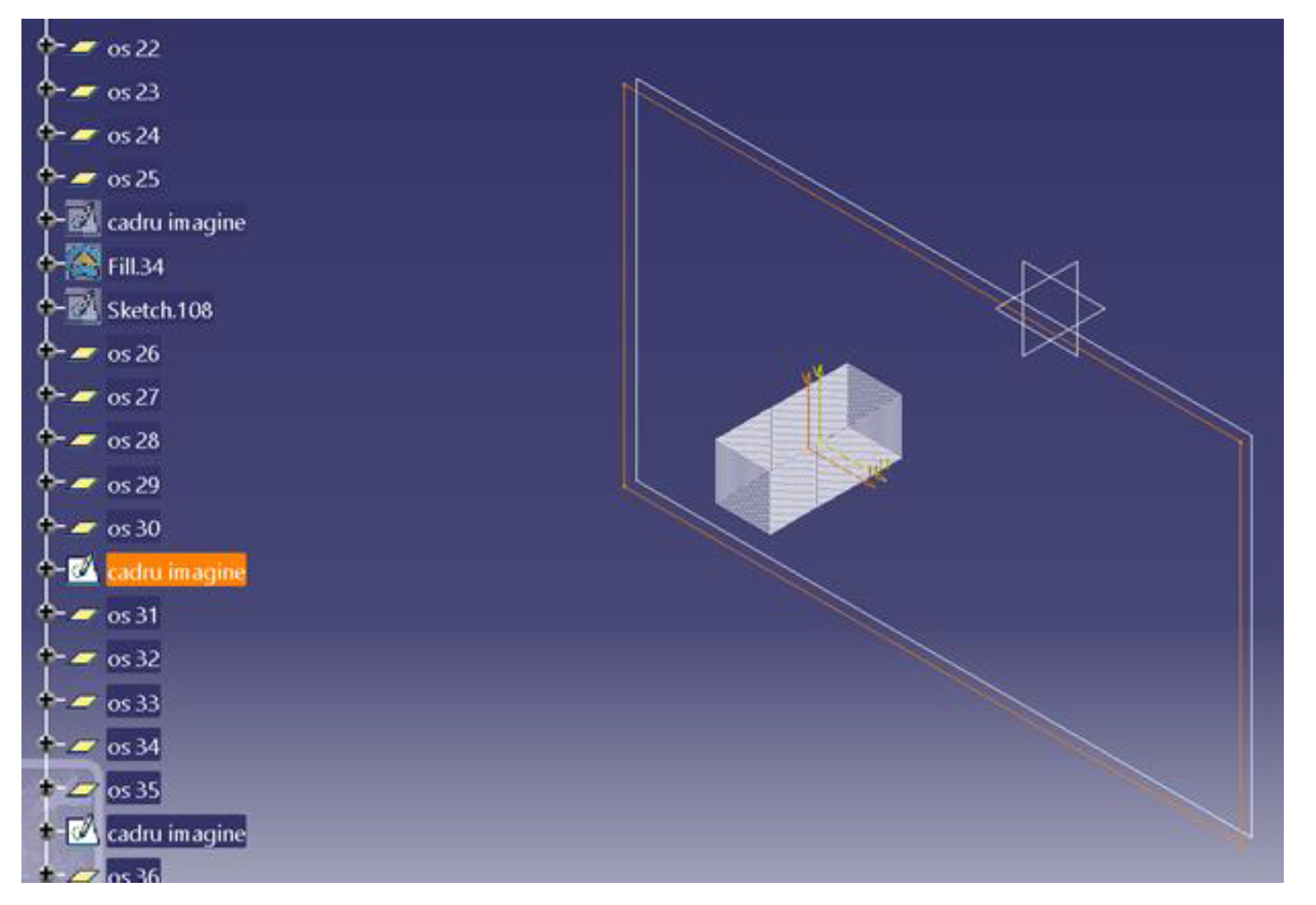
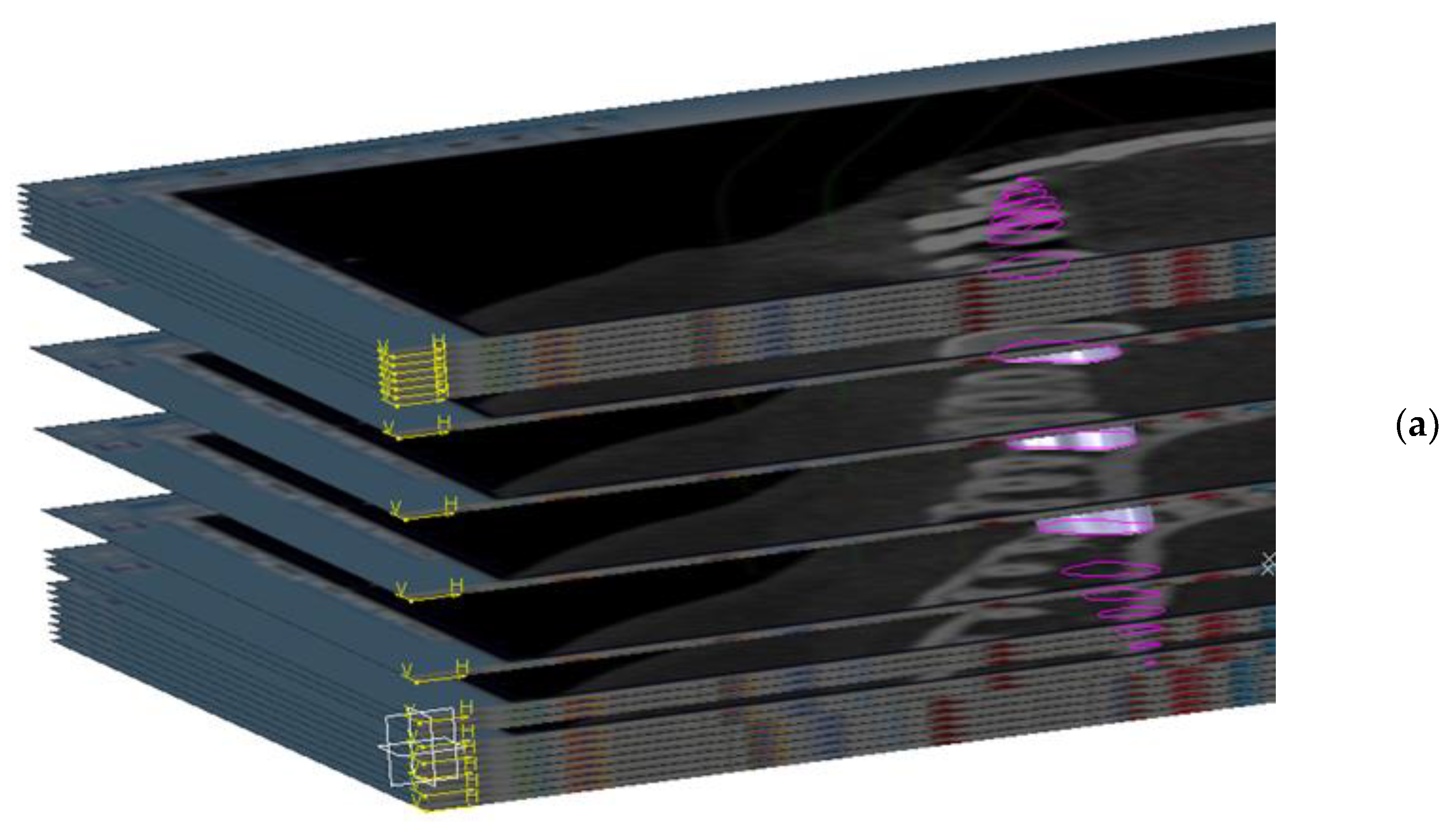
    • The construction of the CBCT image placement plans. In the Catia V5R20 program, 57 planes parallel to each other were built with the help of the plane tool, at a distance of 7 mm from each other. Then, on each plane, a frame with the size 1920 × 1080, equal to the resolution of the image saved in the Planmeca Romexis® Viewer program, was inserted (Figure 1).
    • The plans were constructed with CBCT images, in the GSD (Geometrical Shape Design) module of the CatiaV5 R 20 program. On each frame, introduced in the previous step, the corresponding image saved from the CBCT was introduced; after this step, the frame was transformed into a surface in the GSD module of the Catia V5R20 program. Subsequently, a material was assigned to each surface.
    • The saved image from the CBCT was applied and was set to the selected plane. This was made with the help of the “texture” section of the “properties” menu of the flat surface on which the CT image was applied.
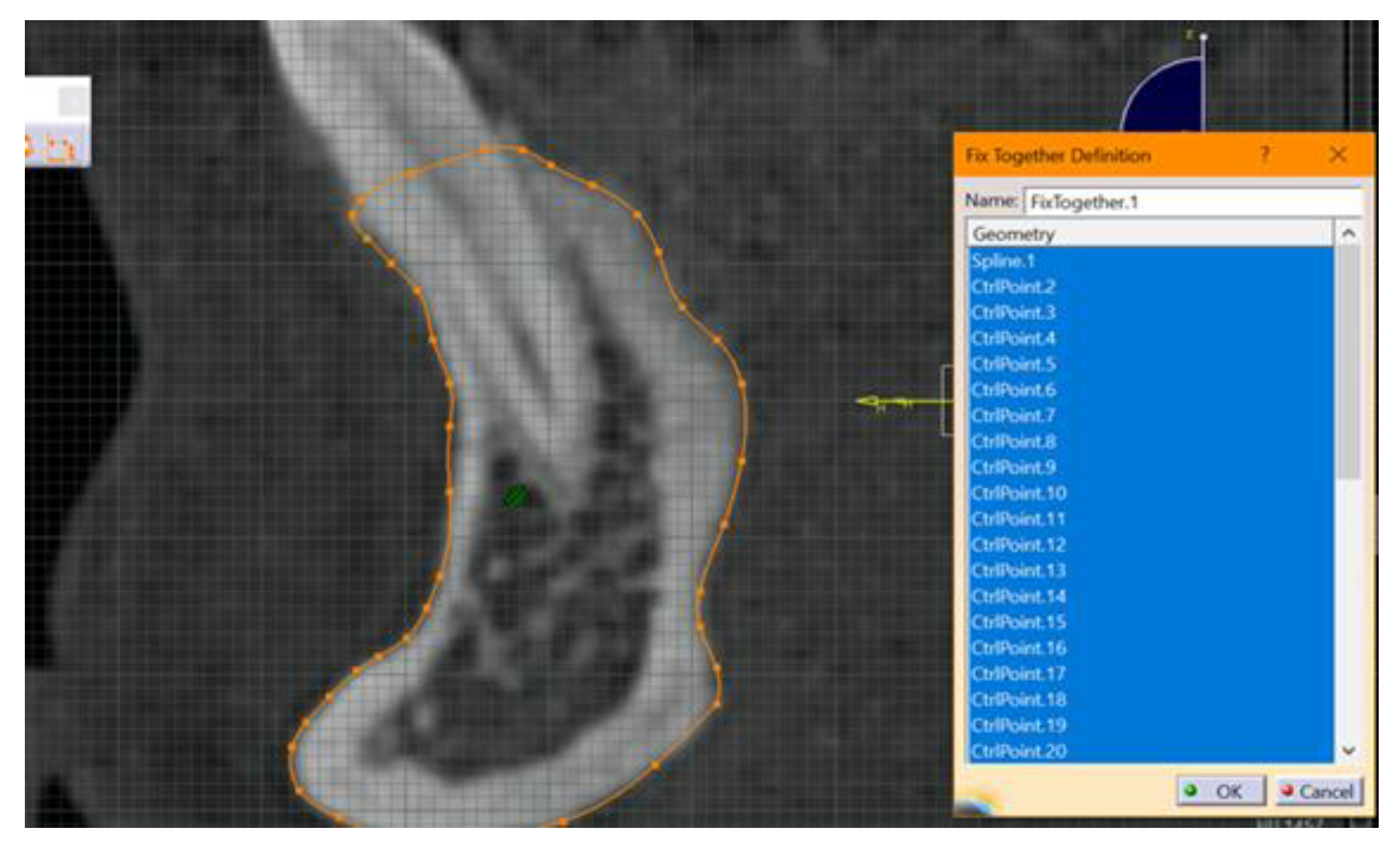
    • The required outline was copied. At this stage, the outer contour of the mandibular bone structure was copied for each section. Copying was done manually using the spline function from the Part design module, from Sketch tools, in Catia V5R20. It is known that the result and quality of this step, the step of making the contour of the section through the bone, depends on the operator’s experience.
    • The next step included fixing and “constraining” the obtained contour. This step is mandatory for each 2D entity in the sections obtained. The constraint aims to fix the points introduced to create curves. If this step is not performed, there is a high risk of error. This step was performed by using the fixed together tool from the Constraints menu. A dimensional constraint was also applied, with the aim of fixing the position of all points in relation to the origin of the work plane (Figure 2).
    • Rearranging the operations in the operations list of the Catia V5 R20 program. This step is necessary in order to easily establish a correlation between sections to the subsequent steps of obtaining the 3D model. It was done by moving the corresponding branches one by one, for each of the 57 sections.
    • Hiding the construction elements used in Catia V5 R20. This is necessary in order to make the contour for the stage of obtaining the 3D model. All the introduced elements (construction plans, frames and images from the sections) were hidden in order to be able to work continuously with the obtained sections. This was done for each plane separately.
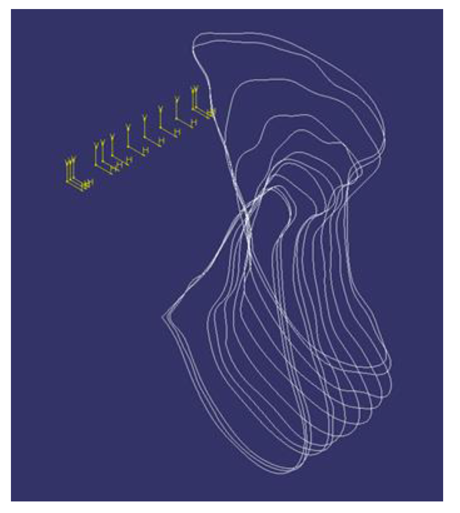
    • Obtaining the 3D model of the mandible section. The construction of the mandible was performed based on the sections from Figure 3.
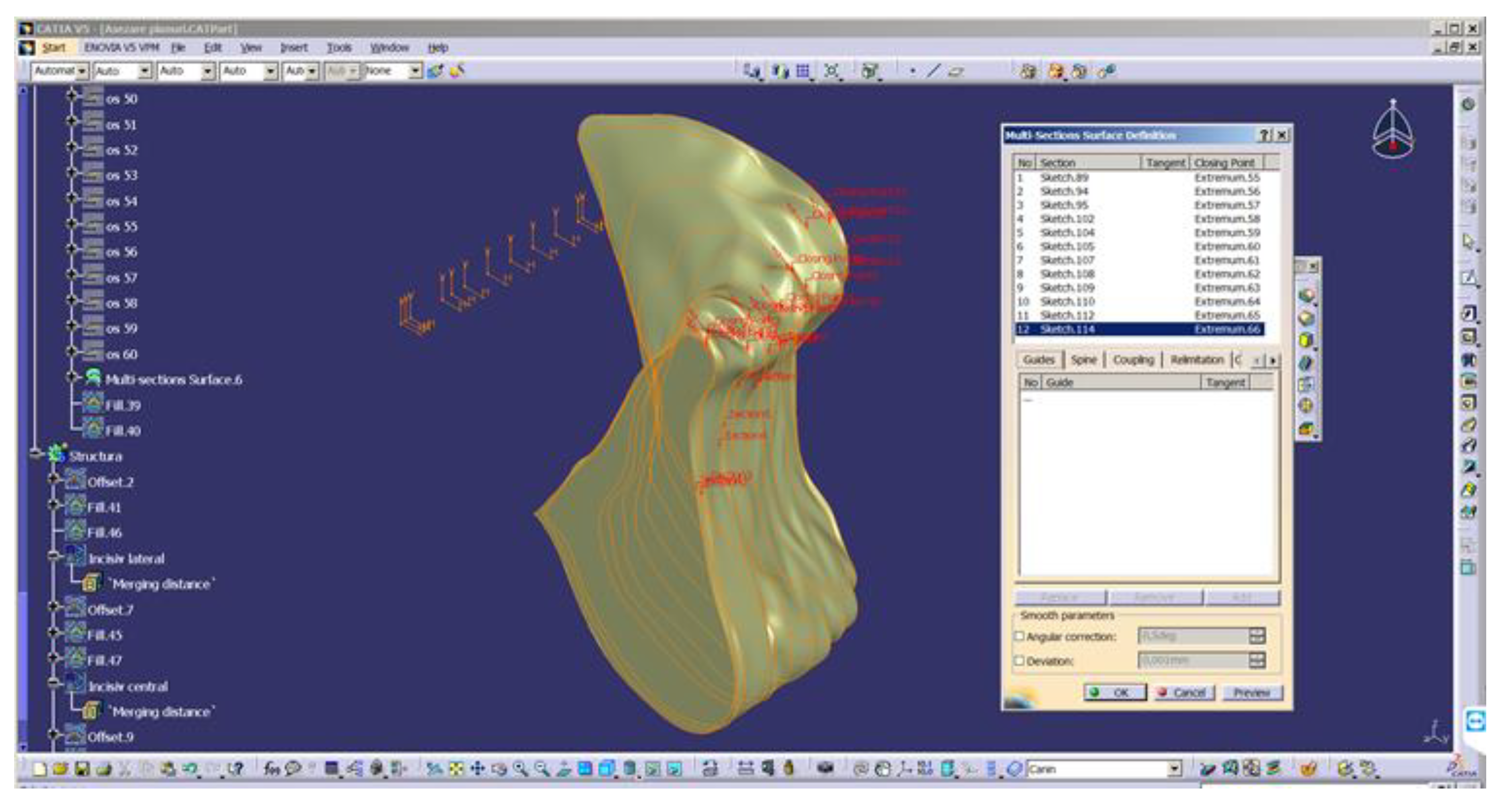
    • Converting 2D sections. The “Multi-sections surface” 3D construction tool was used to convert the previously built 2D sections, as seen in Figure 4. The orientation of the curves was taken into account so that they all had the same tangent direction at the starting point. These were the starting points for the construction of 2D sections, for each section. For this reason, the construction of these sections is particularly important. The order of selection was also taken into account, as shown in the window in Figure 4.
    • The final structure of the mandible. After the construction of the 3D model of the mandibular section, the 2D structure of the sections was hidden.
  • Obtaining the 3D model of the teeth according to the CBCT scan model.
Figure 1. The insertion of a frame on each plane that was previously created.
Applsci 11 03824 g001
Figure 2. Fixing and “constraining” the position of contour points in sections.
Applsci 11 03824 g002
Figure 3. The 2D wireframe sections, necessary to make the 3D model of the mandible.
Applsci 11 03824 g003
Figure 4. Converting 2D sections to 3D model.
Applsci 11 03824 g004
The same operations as for the bone structure were performed in order to obtain the 3D model of the teeth. Each tooth was modeled separately, following the same steps as above. Figure 5 shows the construction of the canine’s geometry and Figure 6 shows the model obtained for three teeth (central incisor, lateral incisor and canine).
Before performing the finite element analysis, the last element, the PDL’s geometry, was created.
The periodontal ligament model was built based on 3D models of the mandible’s periodontium and teeth, applying the principle that the ligament has two common contact surfaces, one with the tooth’s radicular surface and the other with the mandibular bone, mediating the relation between the tooth and the bone [10]. The periodontal ligament is essential during orthodontic treatment for distributing tension and compression loading to the alveolar bone [11]. The modeling of the ligament was performed by calculating the average distance between the bone and the teeth on the CBCT images, and it resulted in a value of 0.4 mm. This thickness is comparable with the 0.4 mm thickness presented in previous studies in this field [12]. In our study, a maximum of 0.4 mm PDL thickness and a minimum of 0.05 mm PDL thickness were used to perform the analysis. Given that the CBCT images do not allow the use of a similar method for 3D modeling of the ligament, because the boundaries between bone, ligament and tooth are not clear, the construction of the ligament cannot be achieved by the same method of approximating the outline used for the bone and tooth. Thus, the average thickness was used as the main construction factor. A duplicate of the tooth was made, and the geometry was copied towards the exterior, at a distance equal to the thickness of the ligament. The tooth shape was subsequently extracted from the respective copy. In this way, the surface of the PDL from the tooth’s side was obtained. Subsequently, the same duplicate intersected with the bone structure. In this way, we obtained a mandibular tooth socket of the mandibular bone.
C.
Stages of periodontal ligament 3D modeling
  • In the first stage, the 3D model with the dimensions obtained after copying the contours from the CBCT was scaled down to the real dimensions. In these contours, each pixel in the CBCT image represents one millimeter in the Catia V5R20 program. The resolution of the introduced images was 1920 × 1080, so that each section was much more enlarged compared to reality. In order to convert the model to a realistic size, the real length was measured on the CBCT and then it was determined in the virtual model of the Catia V5R20 length. This resulted in a ratio of scaling factor F1 = 0.05309038. This scaling factor was applied to the 3D model in order to ensure that the structure composed of the teeth, bone and PDL ligament reflected the real size. This factor was applied in turn to each component element (bone, teeth, periodontal ligament), and then the assembly was performed again in the Assembly Design module. The overall positioning was not altered because the relative positions to the coordinate system were also taken into account when resizing. After scaling, the appearance does not change, only the dimensions.
  • In the second stage, the external dimensions of the ligament were built based on the geometry of the tooth. This scaling allowed the use of the actual dimensions of the ligament and the next step was the modeling of the PDL. For the construction of the ligament, an artifice frequently used in 3D modeling was used. Starting from the shape of the tooth, scaling was applied to obtain a duplicate of the tooth (its shape) at a distance of 0.4 mm from the exterior. For this, the maximum diameter of the tooth was measured in different places. Subsequently, the average value was calculated and the thickness of the ligament was added twice, because it appears on both sides of the tooth. This represented the outer diameter of the ligament. Following this, the ratio between the tooth’s diameter and the ligament’s diameter was made. The value obtained, F2 = 1.023, was used as a scaling factor to obtain the duplicate of the tooth, necessary for the construction of the ligament. In the Catia V5 R20 program, the “scales” function was used. Two parameters are needed for this function: the scale factor, 1.023, and the invariant point of scaling, meaning the scaling center. In our case, the central point of the tooth was chosen. It was built using a line that connected the tip with the apex of the tooth. On this line, the middle of the segment was highlighted and it was selected as an invariant point (reference) for scaling.
  • In the last stage, the tooth geometry was displaced from the obtained ligament, and later, the geometry of the ligament was displaced from the mandibular bone.
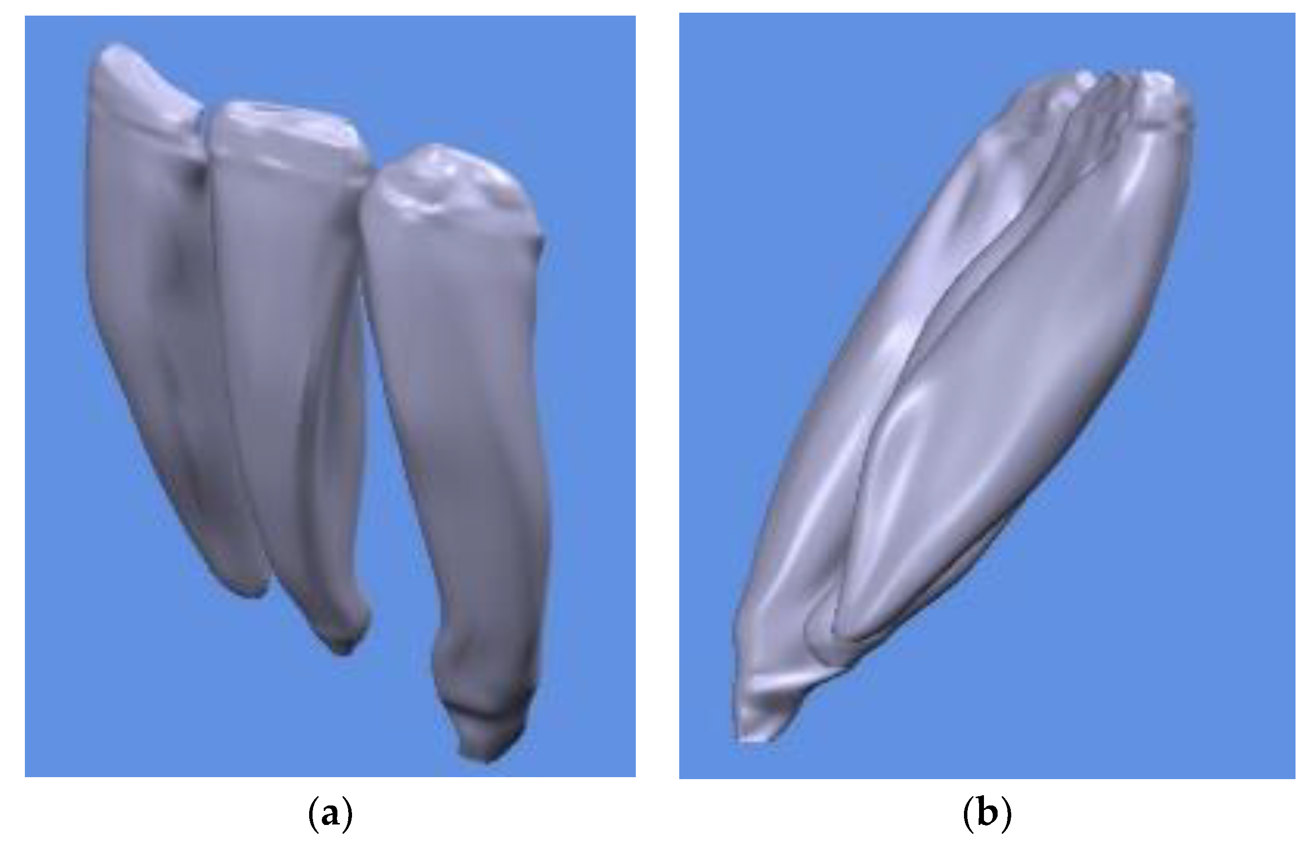
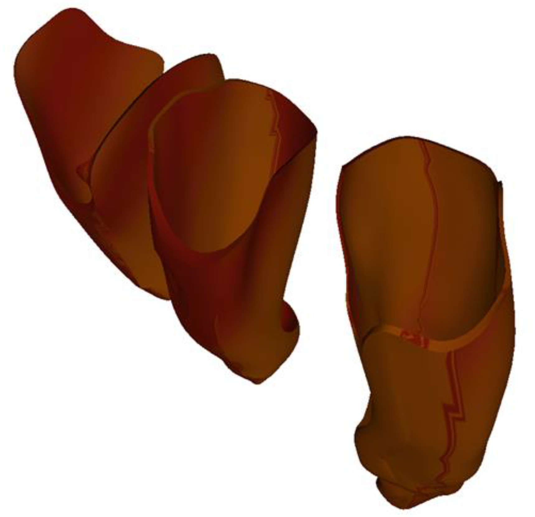
  • The ligaments for the 3 teeth were similar for the two incisors. The thickness of the ligament resulting from this procedure was not constant, but, on average, it was around 0.4 mm. We believe that this approach and construction of the tooth–ligament–bone assembly is the one that best approximates the biological nature of tissues. The obtained periodontal ligaments of the three teeth are illustrated in Figure 7.
  • After obtaining the geometric model of the assembly, we performed the finite element analysis to virtually test the response to various requests. The geometric model was discretized, and, with the help of the equations that describe the reunited phenomena in the form of a basic analytical model, the FEA was performed. The module used was Catia V5 R20—Generative Structural Analysis. The basic analytical model consists of a set of equations that describe the phenomenon studied and the behavior of the material under the action of external stresses. To these, boundary conditions were added. The boundary conditions describe the body’s interaction with the environment. When the field sizes are variable over time, the analytical model must also include their initial conditions, meaning their condition at the beginning of the analysis. This analytical model is the basis for the development of the finite element analytical model, and its predictive variables are the basis of the numerical model’s simulation performance. The analytical model must therefore capture this phenomenon of deformation under the action of external forces. It will contain, in this case, the definition relations of the normal unitary effort and the specific deformations. In order to be able to individualize the behavior of a certain material under the action of external loadings, a constitutive or material law must also be included in the analytical model. For us, this is Hooke’s law, which shows that, in the case of an axially stressed solid material, as long as the external forces do not exceed a certain limit (flow limit), the unit forces are directly proportional to the specific deformations. Material properties were assigned to each component of the assembly in order to perform a finite element analysis.
Therefore, a specific material was used for each type of tissue. The value of E, the modulus of elasticity (Young’s modulus), the breaking strength, the maximum deformation and the Poisson’s ratio were all taken into consideration for our research. The modulus of elasticity is the characteristic of the material and is unique for each type of material (Table 1).
  • 6.
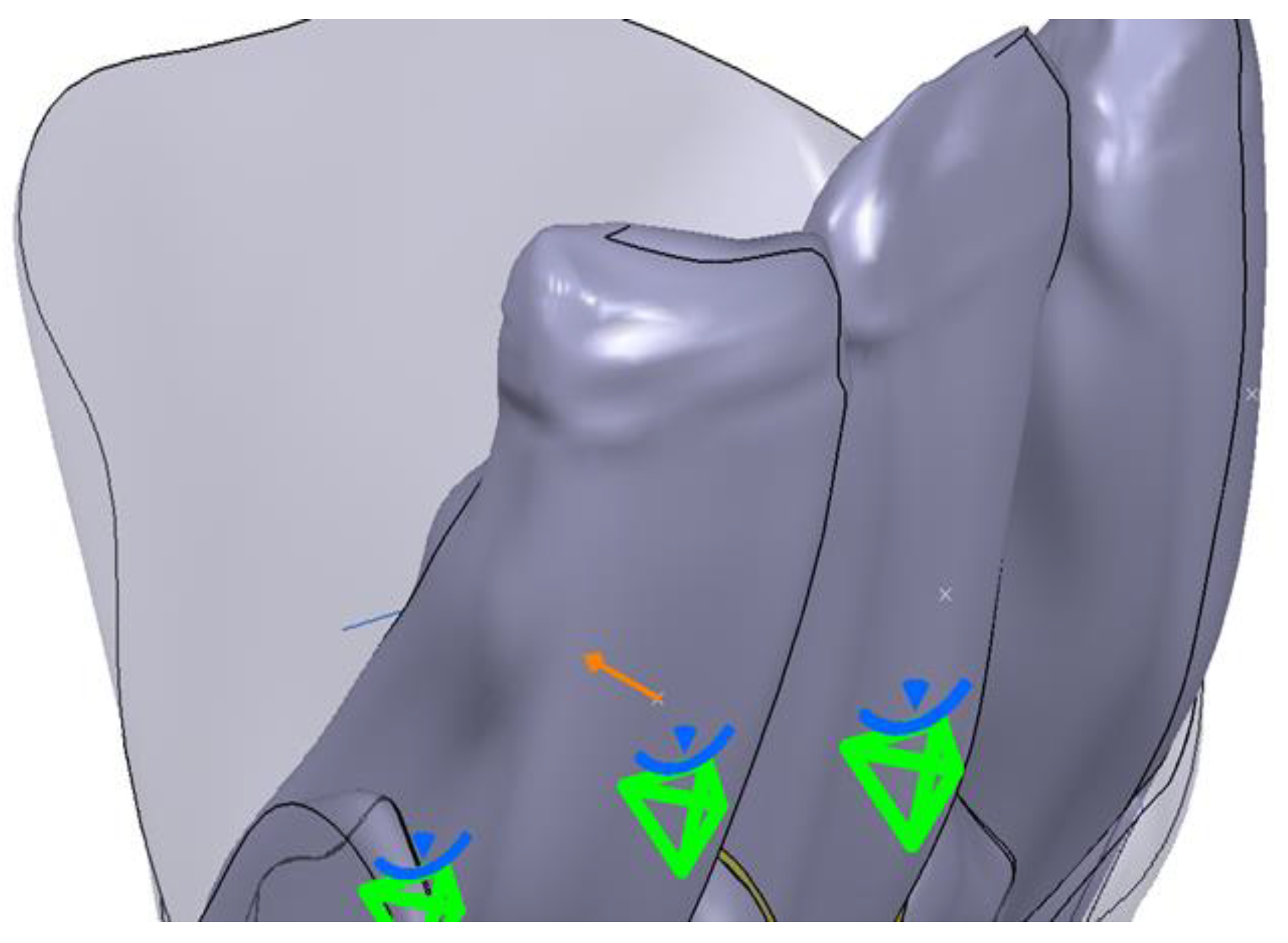
    The operating rules for each element were established in the next step. Thus, a fixing constraint (clamp) was established for the fixed body, the mandibular bone. A clamp was used on the mesial side and one on the distal side. The tooth was considered mobile and the Generative Structural Analysis (GSA) module was used to apply a Fastened Connection constraint. For the PDL, a Fastened Connection constraint in the GSA module was also applied. The next step proceeded with the construction of the model for finite element analysis. This was done by applying boundary conditions and establishing fixed surfaces. For this, the Analysis and Simulation/Generative Structural Analysis workbench was opened. Through this module, the 3D model was further discretized and the conditions of demand and degrees of freedom were imposed. For the surfaces that were in contact, boundary conditions were imposed through the General Analysis Connection tool. This is a very powerful tool that can be used to connect any part of an assembly on an overall model, with or without a handling point. This tool allows any type of geometry to be connected, and it is a general way of connecting two components. The Fastened Connection rigid assembly connection tool was used to assign specific characteristics for simulation. Its purpose was to model a fixed connection between two bodies with a common boundary and the association of a geometric assembly constraint, or a General Analysis Connection type connection. Finally, there were 6 connections between the contact surfaces of the following components: central incisor and central incisor ligament; central incisor ligament and bone; lateral incisor and lateral incisor ligament; lateral incisor ligament and bone; canine and canine ligament; canine ligament and bone.
After the creation of these connections, the surfaces that were considered fixed were constrained with the Clamp tool. These constrained surfaces were the two lateral surfaces, the mesial and the distal surfaces of the mandibular bone. In establishing the values for the discretization network of previously built 3D models, the following parameters were used (Table 2):
  • Size—choosing or changing the size of finite elements;
  • Absolute Sag—the absolute value of the deviation from the boundary—meaning the maximum allowed deviation value for approximating the geometry of the model;
  • Element Type—the type of the finished element.
A uniformly distributed force was applied to each tooth. The Distributed force tool was used. This force was applied to the midpoint of the buccal surface of the tooth crown, as shown in Figure 8.
The recommended position for applying the brackets was respected. The position of the forces for each tooth in part is represented in Figure 8 in the form of x.
Next, the results obtained from virtual experiments performed by simulation using the finite element method are presented.

3. Results

The results present the outcome of the maximum stress in the bone, in the PDL and the absolute displacement after applying a force of 1 N and a force of 0.8 N in bodily direction on the central incisor, lateral incisor and canine. While applying different forces, the data from the same areas were recorded, in order to make a more accurate comparison. The sectioning plan of the tooth, its position, orientation and direction of sectioning were kept unchanged. The same tetrahedral finite elements were taken into account, in cases with no substantial changes in their geometry.
These forces (1 N and 0.8 N) were used due to the fact that they are very light forces that are preferably used on teeth with reduced periodontal support.

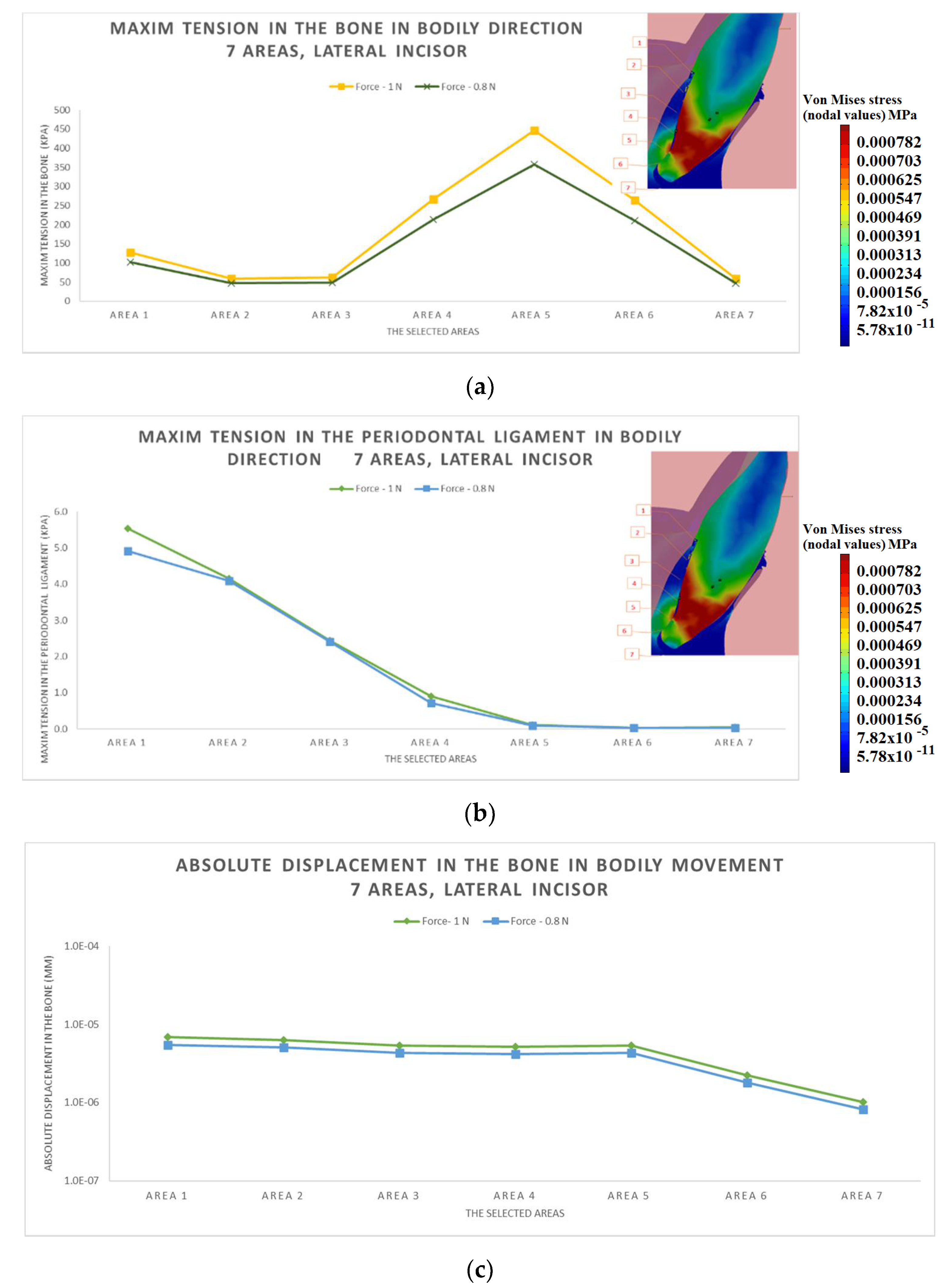
3.1. The Results after Applying the Forces on the Lateral Incisor

At the lateral incisive level, the forces in the lingual direction were applied in order to obtain a bodily movement. In Figure 9a,b, the maximum stresses in the bone and, respectively, in the PDL are represented. The color code applies to the whole ensemble.
As seen in Figure 9a, the highest stress in the bone and in the tooth was exhibited in area 5, the area with minimal ligament thickness. The application of a force in the lingual direction determined in the area with minimal ligament thickness the appearance of a contact point. This produced a lever in this type of movement and, clinically, the occurrence of root resorption could be seen. This explains the maximum stress from area 5, the increasing stress values in the areas with thinner PDL and the decrease in stress in area 6, the area where the PDL thickened again. Considering that area 7, the apex area, is a fixed point and area 1 is a mobile point, the stress should have decreased from area 1 to 7, but it increased in areas 5–6, the areas where the ligament was thinner.
Increasing the force from 0.8 N to 1 N resulted in a noticeable increase in the maximum stress in the PDL in area 1. The increase in the force by 25% resulted in a small increase in the stress (7.2%); therefore, it was not justified to use a force of 1 N instead of a force of 0.8 N. Analyzing the graphic representation, it was observed that the stress in the PDL decreased regularly, without variations, towards the apical area, contrary to the maximum stress identified in the bone (Figure 9b).
In area 5–6, the PDL was very thin, almost non-existent, and the displacement was accelerated by the decreased thickness of the PD. From area 1 to area 5, the appearance of a relatively horizontal curve confirmed that bodily displacement was obtained in this situation. Areas 6 and 7 exhibited lower displacement due to the fact that the apex was fixed to the periodontium. Otherwise, the two curves were similar: as the force increased, an increase in displacement was observed (Figure 9c). Therefore, when the force was increased from 0.8 to 1 N, the stress in the bone increased significantly compared to the values in the ligament; the two lines had a similar appearance for 0.8 N and 1 N. Therefore, stress levels increased in areas 4, 5 and 6, where the PDL was thinning, with a peak in zone 5, where the PDL was greatly diminished and it was not fully functional, and where the PDL was greatly diminished and it was partially functional. In area 7, its value returned to the tendency of the curve.

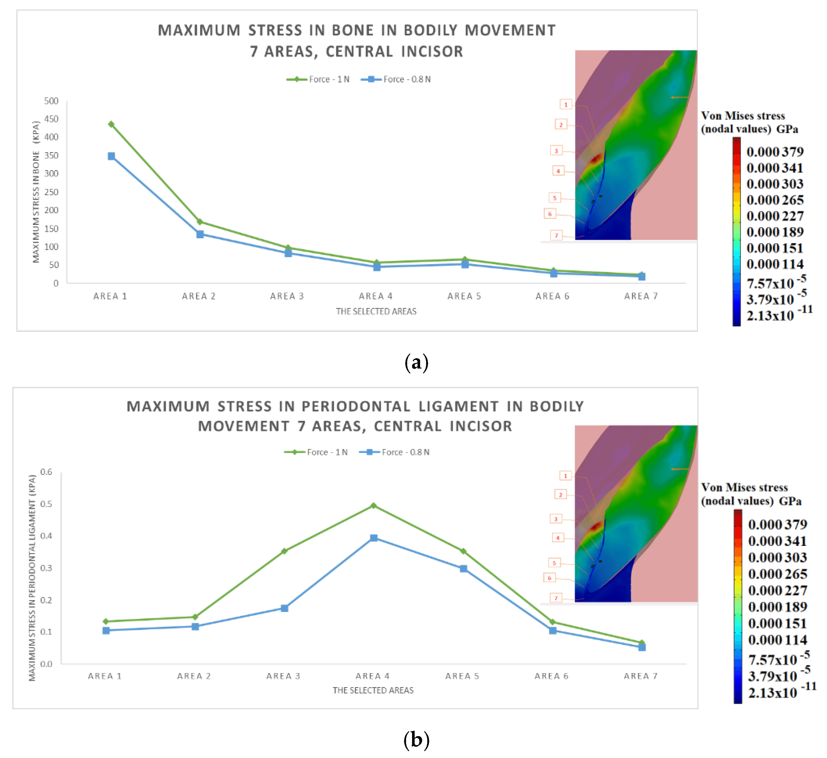
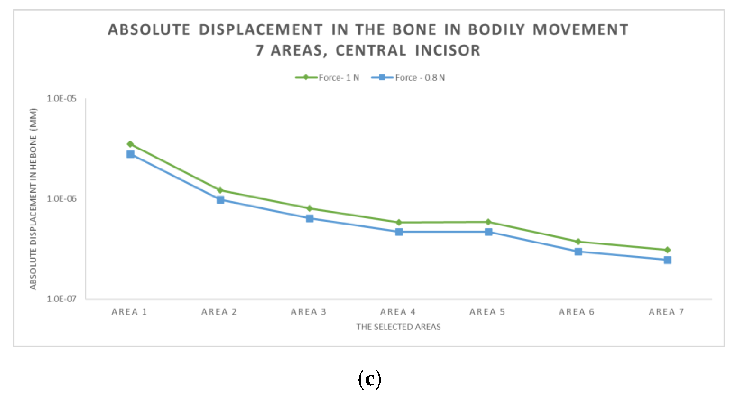
3.2. The Results after Applying the Forces on the Central Incisor

The results respect the color code. The red color corresponds to the maximum stress identified in area 1. Analyzing the stress from one force to another (from 0.8 N to 1 N), as well as the differences for each zone, it was found that the highest stress was in area 1 and it decreased gradually towards area 7, the two curves being identical. Analyzing the stress distribution between area 1 and area 7, it was observed that the difference between the maximum stresses gradually decreased towards the apical area. In this area, the stress was roughly similar, and the differences were indistinguishable.
This phenomenon can be explained by the fact that the force is applied at the coronary level, and area 1 is closest to the force application area, while zone 7 is the furthest. Area 4 is the inflection area between the two curves, and areas 4–5 transition towards the apical area (Figure 10a).
It was observed that stress depends on the PDL’s thickness. Thus, the stress increased starting with area 3, reached its maximum in area 4 and decreased in zone 5. This phenomenon is explained by the fact that in area 4, there was a minimal ligament thickness; in areas 3 and 5, the PDL’s thickness increased; and in area 6, the PDL displayed a relatively normal value. The two curves, both for the force of 1 N and for the force of 0.8 N, are similar in terms of shape; in addition, both exhibited increases in areas 3, 4 and 5. The maximum forces on the two areas of the tooth started approximately from the same area (Figure 10b).
Observing the amplitude of the displacement for each area, the greatest displacement was found in area 1 and the lowest in area 7. Thus, this was bodily displacement with tipping. These two curves had an identical appearance, without any change after an increase in force from 0.8 to 1 N (Figure 10c).

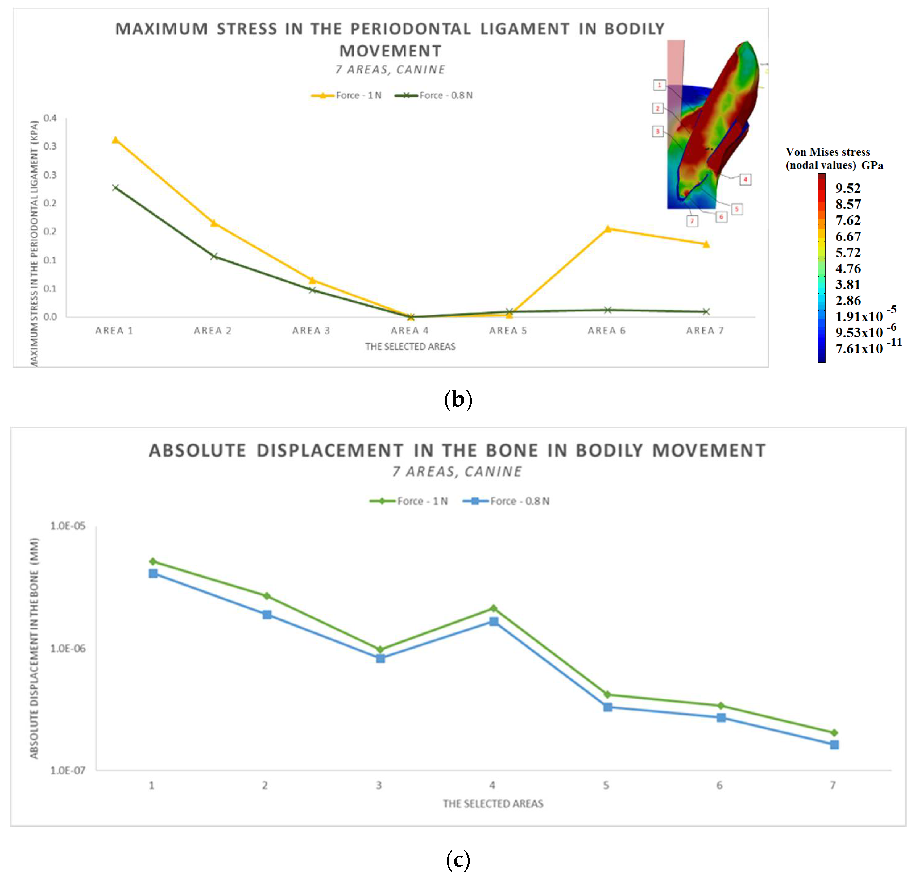
3.3. The Results after Applying the Forces on the Canine

Studying the appearance of the bodily movement in the case of two different forces (1 N and 0.8 N), it was found that the allure of the curve decreased from the cervical margin to the apical area. The maximum stress reached in area 4 is explained by the particular anatomic shape of this tooth (Figure 11a).
The stress in the PDL for bodily movement decreases from the cervical margin towards the apical area. However, in the case of the 1 N force, a substantial increase appeared in areas 6 and 7, in the tooth’s apical proximity, while in area 4 and 5, minimum values were registered (Figure 11b).
Regarding the bodily movement, a different type of displacement was observed in area 4. This phenomenon can be explained by the different anatomy of the tooth in area 4. The particular anatomy of the root influences the displacement, which normally should have been linear descendent (Figure 11c).

4. Discussion

The findings of this study suggest that the degree of displacement is correlated with the PDL’s thickness. These results are in agreement with other studies [15].
Furthermore, stress increases in the PDL depending on the PDL’s degree of thickness. In our study, for the maximum stress in the PDL, for the lateral incisor, it was observed that increasing the force by 25% determined an insignificant increase in the stress. Therefore, it was not justified to use a force of 1 N instead of a force of 0.8 N. These parameters depend on the particular anatomy that was captured by CBCT-based modeling and by object-oriented FEA (real case). These results are similar to those obtained in orthodontic practice.
From a medical point of view, it is recommended to use lower values because higher values could trigger root resorption, particularly in cases with abnormal root shape and increased root length [16,17]. Taking into consideration that the PDL has an absorption function and facilitates the displacement and alignment of teeth during orthodontic treatment [18] in the areas with decreased thickness, the displacement is accelerated or significantly increased. The correlation between the PDL’s thickness and displacement is displayed throughout our study. Analyzing the three graphic representations for the lateral incisor (Figure 9a–c), it can be noticed that the displacement is higher in the area where the maximum bone stress is highest, and in area 5–6, the displacement is increased. This outcome is due to the minimal ligament thickness. Thus, these aspects should be well known before treatment planning in order to apply the necessary therapy according to the particularities of each patient. In order to analyze the effects of forces on the atypical anatomy of the root, FEA is a suitable, non-invasive method with results that can be subsequently applied in practice, in orthodontic treatment.
Regarding the type of displacement obtained, it can be observed, in the case of the three teeth (central incisor, lateral incisor and canine), that a bodily displacement with tipping was obtained. This aspect is highlighted by the shape of the curve. A horizontal line of the curve means that the movement is a pure bodily movement. Nevertheless, in our study, the line is descendent, which means that the movement is not a pure bodily movement, and it is a bodily displacement with tipping (Figure 9c, Figure 10c and Figure 11c).
Comparing the stress values in the ligament and in the bone, it was observed that the highest stress developed in the lateral incisor due to the minimal ligament thickness in area 4. Our results are comparable with the findings of Jing et al. [19], who found the highest stress in the central incisor. The results of our study would have been similar to those from previous studies, provided that the anatomy of the mandibular teeth would not be atypical compared to the maxillary teeth. This highlights the need for studies on the anatomical features of the teeth and periodontium, FEA being one of the most recommended methods. The highest maximum stress was found in area 1, in proximity to the cervical margin. This is in agreement with other studies [19].
The orthodontic–periodontal interrelationship is well known and systematically studied [20,21,22], particularly since the reduced periodontium is considered at risk regarding orthodontic treatment [23]; thus, the necessity of studies in this field is justified. This type of periodontium has low resistance to mechanical stress [24]. It is well known from practice and the literature that the most common root resorption occurs at the level of lateral and central incisors [17,25]. The explanation of this phenomenon is given by the radiological anatomy of these teeth (curved shape), the position on the arch (it is positioned with predilection towards lingual), the thinner cortex at this level and, especially in the case of the mandible, in the hypomochlion area, the PDL is thinner. Therefore, the forces will be concentrated at the center of rotation, which is dependent on the periodontal level. It is known that a reduced periodontium favors tipping movement and root resorption. A sufficient thickness of the PDL is also required to properly transmit the force through the bone and to correctly displace the teeth during orthodontic treatment. Studies show that the mandibular incisor region is the most common site and most prevalent for bone dehiscence and gingival recession [26,27], due to anatomical restrictions of the alveolar bone area, mainly in the antero–posterior aspect [28]. There has been discovered a correlation between alveolar bone loss and gingival recession after mandibular incisor retroclination [29].
Nevertheless, this study has some limitations. The model used for the FEA included only three teeth and their periodontium and they were considered isotropic. In addition, another limitation of the current study is that in orthodontics, the application of forces with a single point of application is very rare and can only be achieved with the use of specific techniques. Future research should consider analyzing the most widely used orthodontic techniques and extending the research on the entire mandible and even on the maxilla, in order to be able to compare the results. It should include several different characteristics for the PDL, such as an anisotropic ligament.

5. Conclusions

It was found that the maximum value of bone stress for the lateral incisor was in area 5, due to the minimal ligament thickness; it reached 448 KPa for the force of 1 N and 358 KPa for the force of 0.8 N. From a biomechanical point of view, a grade 2 lever was formed, due to the atypical root anatomy. The point of application of the resisting force (area 5, area with minimal PDL thickness) is between the fix point (tooth’s root) and that of the active force (force applied to the tooth). Regarding the displacement of the lateral incisor, starting with area 5, the area with minimal ligament thickness, there was a decreasing tendency of the curve. In area 5, there was a risk of bone resorption occurrence due to increased stress, due to atypical root anatomy and longitudinal root depression. The increased displacement of the bone was determined by the minimal ligament thickness, as a result of the PDL’s function, as the PDL optimizes the transfer of the forces and regulates orthodontic tooth movement. In the central incisor, the maximum bone stress was in area 1. In comparison, the maximum bone stress in the lateral incisor was in area 5, as a result of an atypical root anatomy. In areas 3, 4 and 5, areas with minimal ligament thickness, an increase in ligament tension was observed. Displacement was favored in areas 4–5 by the minimal ligament thickness; the curve had a constant horizontal appearance. This could determine root resorption. At the lateral incisor, the maximum stress in the bone in the area with the maximum increase for area 5 was 448 KPa, and in area 1, it was 128 KPa. In the canine, the maximum stress in the bone, in the area with the maximum increase, for area 4 was 89 KPa, and in area 1, it was 203 KPa. At the central incisor, the maximum stress in the bone, in the area with the maximum increase at the cervical margin for area 1 was 436 KPa.
Comparing the two curves of the central and lateral incisor, it was observed that:
  • The difference in increase is much higher at the lateral incisor (approx. 300 KPa), compared to the canine (approximately 100 KPa).
  • The difference in increase is explained by the specific mode of action of the force in the two cases. For the lateral incisor, the lever is of degree 2, with the force arm between zone 5 and zone 1; for the canine, the lever is of degree 1, and the arm of force between zone 1 and zone 4.
  • Due to the lever configuration, a compression force of the ligament appears in area 6–7 and this causes the PDL’s increase.
  • In area 4, the risk of bone resorption due to increased stress is observed, as a result of atypical root anatomy. The minimal ligament thickness in area 4 causes increased displacement of the bone. This occurs as a result of the PDL’s function, which optimizes the transfer of the forces and regulates orthodontic tooth movement.
  • The displacement is a bodily movement with tipping.
Considering that the stress is influenced by the tooth’s morphology and the periodontal status, it can be concluded that the results obtained are similar to those from clinical practice. In addition, the outcome of this study demonstrates the correlation between the clinical results and FEA. Specific implications of orthodontic forces and biomechanical compression on the periodontal tissues are difficult to quantify; therefore, FEA is mandatory in order to achieve a treatment that is planned according to the patient’s particular situation. This is even more important in patients with reduced periodontium that are predisposed to recessions.

Author Contributions

Conceptualization, I.-A.S. and M.A.; methodology, S.M.S. and M.A.; software, D.-C.K.-N.; validation, S.M.S. and N.C.; formal analysis, I.-A.S.; investigation, S.T. and A.M.; resources, S.M., M.P. and N.C.; data curation, I.-A.S. and A.M.; writing—original draft preparation, I.-A.S. and M.A.; writing—review and editing, I.-A.S. and N.C.; visualization, A.M., I.L. and M.A.; supervision, S.M.S., M.A., N.C. and I.L.; project administration, M.P. and S.M.; funding acquisition, S.M. All authors have read and agreed to the published version of the manuscript.

Funding

This study was partially funded through a PhD scholarship offered by the Romanian Ministry of Education to Ioana-Andreea Sioustis, a PhD student at the University of Medicine and Pharmacy “Grigore T. Popa” Iasi, Romania and partially by Romanian Ministry of Education and Research, CNCS-UEFISCDI, project number PN-III-P1-1.1-TE-2019-1921, within PNCDI III.

Institutional Review Board Statement

The study was conducted according to the guidelines of the Declaration of Helsinki and approved by the Ethics Committee of the University of Medicine and Pharmacy from Iasi, Romania (Protocol identification code 29.01.2020/2540).

Informed Consent Statement

Any research article describing a study involving humans should contain this statement. Please add “Informed consent was obtained from all subjects involved in the study.” OR “Patient consent was waived due to REASON (please provide a detailed justification).” OR “Not applicable.” for studies not involving humans. You might also choose to exclude this statement if the study did not involve humans.

Data Availability Statement

The data used to support the findings of this study are available from the correspondence authors upon request.

Acknowledgments

Sorina Mihaela Solomon and Ionut Luchian have a contribution equal to that of the first author.

Conflicts of Interest

The authors declare no conflict of interest.

References

  1. Bramanti, E.; Cervino, G.; Lauritano, F.; Fiorillo, L.; D’Amico, C.; Sambataro, S.; Denaro, D.; Famà, F.; Ierardo, G.; Polimeni, A.; et al. FEM and Von Mises Analysis on Prosthetic Crowns Structural Elements: Evaluation of Different Applied Materials. Sci. World J. 2017, 3. [Google Scholar] [CrossRef] [Green Version]
  2. Lauritano, F.; Runci, M.; Cervino, G.; Fiorillo, L.; Bramanti, E.; Cicciù, M. Three-dimensional evaluation of different prosthesis retention systems using finite element analysis and the Von Mises stress test. Minerva Stomatol. 2016, 65, 353–367. [Google Scholar]
  3. Goel, V.K.; Khera, S.C.; Ralson, J.L.; Chang, K.H. Stresses at the dentino-enamel junction of human teeth: A finite element investigation. J. Prosthet. Dent. 1991, 66, 451–459. [Google Scholar] [CrossRef]
  4. Butnaru-Moldoveanu, S.A.; Munteanu, F.; Forna, N.C. Virtual Bone Augmentation in Atrophic Mandible to Assess Optimal Implant-Prosthetic Rehabilitation—A Finite Element Study. Appl. Sci. 2020, 10, 401. [Google Scholar] [CrossRef] [Green Version]
  5. Carpegna, G.; Alovisi, M.; Paolino, D.S.; Marchetti, A.; Gibello, U.; Scotti, N.; Pasqualini, D.; Scattina, A.; Chiandussi, G.; Berutti, E. Evaluation of Pressure Distribution against Root Canal Walls of NiTi Rotary Instruments by Finite Element Analysis. Appl. Sci. 2020, 10, 2981. [Google Scholar] [CrossRef]
  6. Huang, H.-L.; Tsai, M.-T.; Yang, S.-G.; Su, K.-C.; Shen, Y.-W.; Hsu, J.-T. Mandible Integrity and Material Properties of the Periodontal Ligament during Orthodontic Tooth Movement: A Finite-Element Study. Appl. Sci. 2020, 10, 2980. [Google Scholar] [CrossRef]
  7. Luchian, I.; Moscalu, M.; Martu, I.; Curca, R.; Vata, I.; Stirbu, C.; Tatarciuc, M.; Martu, S. A FEM Study regarding the Predictability of Molar Uprighting Associated with Periodontal Disease. Int. J. Med. Dent. 2018, 22, 183–188. [Google Scholar]
  8. Krishnan, V.; Davidovitch, Z. Cellular, molecular, and tissue-level reactions to orthodontic force. Am. J. Orthod. Dentofac. Orthop. 2006, 129, 469.e1–469.e32. [Google Scholar] [CrossRef] [PubMed]
  9. Theerasopon, P.; Kosuwan, W.; Charoemratrote, C. Stress assessment of mandibular incisor intrusion during initial leveling in continuous arch system with different archwire shapes of superelastic nickel-titanium: A three-dimensional finite element study. Int. J. Health Allied Sci. 2019, 8, 92–97. [Google Scholar]
  10. Nishihira, M.; Yamamoto, K.; Sato, Y.; Ishikawa, H.; Natali, A.N. Mechanics of periodontal ligament. Dental Biomech. 2003, 20–34. [Google Scholar] [CrossRef]
  11. Dorow, C.; Krstin, N.; Sander, F.G. Experiments to determine the material properties of the periodontal ligament. J. Orofac. Orthop. 2002, 63, 94–104. [Google Scholar] [CrossRef] [PubMed]
  12. Schmidt, F.; Lapatki, B.G. Effect of variable periodontal ligament thickness and its non-linear material properties on the location of a tooth’s centre of resistance. J. Biomech. 2019, 94, 211–218. [Google Scholar] [CrossRef]
  13. Xia, Z.; Jiang, F.; Chen, J. Estimation of periodontal ligament’s equivalent mechanical parameters for finite element modeling. Am. J. Orthod. Dentofac. Orthop. 2013, 143, 486–491. [Google Scholar] [CrossRef] [PubMed] [Green Version]
  14. Singh, J.R.; Kambalyal, P.; Jain, M.; Khandelwal, P. Revolution in Orthodontics: Finite element analysis. J. Int. Soc. Prev. Community Dent. 2016, 6, 110–114. [Google Scholar] [CrossRef] [Green Version]
  15. Li, Y.; Jacox, L.A.; Little, S.H.; Ko, C.C. Orthodontic tooth movement: The biology and clinical implications. Kaohsiung J. Med. Sci. 2018, 34, 207–214. [Google Scholar] [CrossRef] [PubMed] [Green Version]
  16. Sameshima, G.T.; Sinclair, P.M. Predicting and preventing root resorption: Part I. Diagnostic factors. Am. J. Orthod. Dentofac. 2001, 119, 505–510. [Google Scholar] [CrossRef]
  17. Jung, Y.H.; Cho, B.H. External root resorption after orthodontic treatment: A study of contributing factors. Imaging Sci. Dent. 2011, 41, 17–21. [Google Scholar] [CrossRef] [Green Version]
  18. Nakamura, N.; Ito, A.; Kimura, T.; Kishida, A. Extracellular Matrix Induces Periodontal Ligament Reconstruction In Vivo. Int. J. Mol. Sci. 2019, 20, 3277. [Google Scholar] [CrossRef] [Green Version]
  19. Jing, Y.; Han, X.; Cheng, B.; Bai, D. Three-dimensional FEM analysis of stress distribution in dynamic maxillary canine movement. Sci. Bull. 2013, 58, 2454–2459. [Google Scholar] [CrossRef] [Green Version]
  20. Calniceanu, H.; Stratul, S.; Rusu, D.; Jianu, A.; Boariu, M.; Nica, L.; Ogodescu, A.; Sima, L.; Bolintineanu, S.; Anghel, A.; et al. Changes in clinical and microbiological parameters of the periodontium during initial stages of orthodontic movement in patients with treated severe periodontitis: A longitudinal site-level analysis. Exp. Ther. Med. 2020, 6, 199. [Google Scholar] [CrossRef]
  21. Machoy, M.; Szyszka-Sommerfeld, L.; Koprowski, R.; Wawrzyk, A.; Woźniak, K.; Wilczyński, S. Assessment of Periodontium Temperature Changes under Orthodontic Force by Using Objective and Automatic Classifier. Appl. Sci. 2021, 11, 2634. [Google Scholar] [CrossRef]
  22. Sioustis, I.-A.; Martu, M.-A.; Aminov, L.; Pavel, M.; Cianga, P.; Kappenberg-Nitescu, D.C.; Luchian, I.; Solomon, S.M.; Martu, S. Salivary Metalloproteinase-8 and Metalloproteinase-9 Evaluation in Patients Undergoing Fixed Orthodontic Treatment before and after Periodontal Therapy. Int. J. Environ. Res. Public Health 2021, 18, 1583. [Google Scholar] [CrossRef]
  23. Rasperini, G.; Acunzo, R.; Cannalire, P.; Farronato, G. Influence of Periodontal Biotype on Root Surface Exposure During Orthodontic Treatment: A Preliminary Study. Int. J. Periodontics Restor. Dent. 2015, 35, 655–675. [Google Scholar] [CrossRef]
  24. Gorbunkova, A.; Pagni, G.; Brizhak, A.; Farronato, G.; Rasperini, G. Impact of Orthodontic Treatment on Periodontal Tissues: A Narrative Review of Multidisciplinary Literature. Int. J. Dent. 2016, 4723589. [Google Scholar] [CrossRef] [PubMed] [Green Version]
  25. Abuabara, A. Biomechanical aspects of external root resorption in orthodontic therapy. Med. Oral Patol. Oral Cirugía Bucal 2007, 12, 610–613. [Google Scholar]
  26. Albandar, J.M. Global risk factors and risk indicators for periodontal diseases. Periodontology 2000 2002, 29, 177–206. [Google Scholar] [CrossRef]
  27. Wehrbein, H.; Bauer, W.; Diedrich, P. Mandibular incisors, alveolar bone and symphysis after orthodontic treatment: A retrospective study. Am. J. Orthod. Dentofac. Orthop. 1996, 110, 239–246. [Google Scholar] [CrossRef]
  28. Swasty, D.; Lee, J.S.; Huang, J.C.; Maki, K.; Gansky, S.A.; Hatcher, D.; Miller, A.J. Anthropometric analysis of the human mandibular cortical bone as assessed by cone-beam computed tomography. J. Oral Maxillofac. Surg. 2009, 67, 491–500. [Google Scholar] [CrossRef]
  29. Vasconcelos, G.; Kjellsen, K.; Preus, H.; Vandevska-Radunovic, V.; Hansen, B.F. Prevalence and severity of vestibular recession in mandibular incisors after orthodontic treatment: A case-control retrospective study. Angle Orthod. 2012, 82, 42–47. [Google Scholar] [CrossRef]
Figure 5. Construction of the canine’s geometry: (a) necessary sections for the canine, based on CBCT; (b) the construction of the canine geometry based on the sections.
Applsci 11 03824 g005aApplsci 11 03824 g005b
Figure 6. The model obtained for three teeth: (a) facial aspect (from left to right—the central incisor, the lateral incisor and the canine); (b) lingual aspect (from left to right—the central incisor, the lateral incisor and the canine).
Applsci 11 03824 g006
Figure 7. Illustration of the 3 ligaments (from left to right—the central incisor, the lateral incisor and the canine).
Applsci 11 03824 g007
Figure 8. Place of application of the forces for each tooth, represented with x.
Applsci 11 03824 g008
Figure 9. (a) Maximum stress in the bone for the lateral incisor. (b) Maximum stress in the PDL for the lateral incisor. (c) Absolute displacement in the bone in bodily movement for the lateral incisor.
Applsci 11 03824 g009
Figure 10. (a) Maximum stress in the bone in the central incisor. (b) Maximum stress in periodontal ligament in the central incisor. (c) Absolute displacement in the bone in bodily movement for the central incisor.
Applsci 11 03824 g010aApplsci 11 03824 g010b
Figure 11. (a) Maximum stress in the bone for the canine. (b) Maximum stress in the periodontal ligament in the canine. (c) Absolute displacement in the bone in bodily movement.
Applsci 11 03824 g011aApplsci 11 03824 g011b
Table 1. Material properties.
MaterialYoung’s ModulusPoisson’s Ratio
PDL7.1 × 10-4 GPa [13]0.4
Bone140 GPa [14]0.3
Tooth20.3 GPa [14]0.3
Table 2. Finite element characteristics for each component.
ElementSize (mm)Absolute Sag (mm)El. Type
Bone0.80.5Linear tetrahedral
PDL central incisor0.30.1Linear tetrahedral
Central incisor1.2720.203Linear tetrahedral
PDL lateral incisor0.30.1Linear tetrahedral
Lateral incisor1.3130.21Linear tetrahedral
PDL canine0.30.1Linear tetrahedral
Canine1.4840.237Linear tetrahedral
Publisher’s Note: MDPI stays neutral with regard to jurisdictional claims in published maps and institutional affiliations.

