Abstract
An experimental investigation on the accuracy of dynamically determined tensile force in tie-rods by applying the interferometric radar technique was performed. Tie-rods were used in historical masonry constructions for absorbing thrusts of arches and vaults, and the radar interferometry may represent a fast and easy non-destructive approach for the tensile force identification in the occasion of structural assessments. Laboratory dynamic tests on a cable under a known tensile force show that, provided that a suitable dynamic identification model is used, tensile force evaluations made stating from interferometric radar measurements were characterized by a very good accuracy (mean error in the tensile force estimation less than 2%), comparable with evaluations made starting from accelerometric measurements. In particular, the dynamic identification model considered is a modified version of a model proposed in the literature. The influence on the accuracy in the determination of the tensile force of some features of the experimental setup, like, e.g., the employ of corner reflectors, is discussed.
1. Introduction
The preservation of the architectural heritage is assuming an increasing relevance, not only for the safeguard of the cultural and historical identity of a country but also for giving to future generations the possibility of benefit from it, according to ONU Agenda 2030 Sustainable Development Goal 11.
To this aim, an important step is to develop and employ effective and accurate non-destructive testing (NDT) techniques for determining the relevant structural features of the examined heritage construction and for characterizing damage and defects. Indeed, the suitable use of NDT allows for gathering data needed for constructing representative structural models without inducing damages. This knowledge phase is crucial for avoiding misjudgments in the assessment and in the design of strengthening works, resulting in the prevision of insufficient or, vice versa, excessive structural interventions.
For the special but very common case of historical masonry constructions, different NDT methods are available [1] for different purposes. However, NDT methods usually provide qualitative results and, in some cases, can be time-expensive or technically complex or may give unreliable results. For this reason, the research community is involved in increasing theoretical and experimental efforts on NDT to obtain more reliable and quantitative results [2] and to make applying NDT methods faster and simpler.
One of the possible applications of NDT for historical masonry constructions is the assessment of the effectiveness of past or recent strengthening interventions [3,4]. In particular, a very diffused traditional reinforcing technique is represented by the introduction of tie-rods [5]. The latter improve the structural behavior mainly by absorbing the horizontal thrusts exerted by arches and vaults but also improve the connection between different masonry elements, yielding a more efficient structural behavior on the occasion of seismic events [6,7].
Anyway, the effectiveness of tie-rods is basically related to the value of the tensile force exerted on the connected masonry members, which can vary over time due to phenomena like steel relaxation, material corrosion damage, differential foundation settlements, supports spreading, and other causes [8,9]. In these cases, the structural safety level may be severely reduced. Consequently, for assessing a masonry construction, it is very important on one hand to develop structural analysis approaches for accurately determining the thrust exerted by arches and vaults [10,11], and on the other hand to study experimental in situ NDT techniques for evaluating the actual value of the tensile force in tie-roads. Each piece of information is required for the evaluation of the structural safety level and for managing eventual interventions aimed at restoring a suitable value of the tensile force.
Essentially, there are three approaches for experimentally estimating tensile force in tie-rods: static methods [12,13], dynamic methods [14,15,16,17,18], and a combination of both [19]. In the present study, only dynamic methods are addressed since they are generally more convenient in terms of time and costs.
The fundamental idea behind dynamic methods is that in a dynamic test, the tensile force in a tie-rod can be related to its modal parameters, particularly its natural frequencies and mode shapes. As a consequence, a dynamic approach consists, first, in exciting and measuring the vibrations of the tie-rod and then in estimating the modal parameters by using a modal identification technique [20,21,22].
In the last decade, several research contributions on dynamic approaches for identifying the tensile force in tie-rods have appeared in the literature. Some of them require the determination of the modal shapes [23,24,25,26], eventually by using model updating techniques based on the comparison between experimental and numerical results, the latter determined by FEM simulations [23,26]. Other approaches use additional masses for perturbating the modal frequencies [27]; also, in this case, the identification could be supported by the comparison with FEM results and optimization methods based on genetic algorithms [28]. A relevant issue deepened in the literature is the influence of the constraints at the ends of the tie-rod on the dynamic behavior, and in particular, on the frequency of free vibrations. The more refined methods consider diffuse elastic constraints on the terminal portions of the tie-rod, represented by the Winkler model [29,30]. The approach in [31] combines diffuse elastic end constraints with the possibility of having concentrated masses; moreover, the shear deformability of the tie-rod is taken into account by using a Timoshenko beam model.
Even though dynamic methods are particularly suitable for the estimation of tensile force in tie-rods of historic constructions [32], there are still some ways for improvements of the experimental setup required for vibration measurement. Indeed, the vibrations of tie-rods are usually measured through accelerometers. The latter are very accurate instruments, but their installation is time-expensive, technically complex and requires full access to the tie-rod. These drawbacks can limit the diffusion of dynamic methods in practical applications.
To overcome these drawbacks, some alternative measuring techniques have been studied; the first contributions in this direction concerned the similar, but somewhat different, case of the stay cables. In particular, the goal of contactless measurements of vibrations of cables has been pursued by using the radar interferometer [33,34], the laser vibrometer [35], vision-based methods [36]. In [37], regarding the case of tie-rods of historic construction, acoustic recording by general-purpose microphones has been employed. Finally, in [38], both the laser vibrometer and the radar interferometer have been used for determining the first natural frequency of tie-rods belonging to monumental buildings, but no results in terms of tensile force were reported.
In this context, the main purpose of the present study is to experimentally evaluate the effectiveness of an innovative experimental technique, based on the principle of radar interferometry, for the application represented by the estimation of tensile force in tie-rods. The radar interferometry allows for remote and quick measurement of structural displacements and vibrations [39,40,41,42] overcoming the need to install a sensor on the structure. These features make this technique very appealing; nevertheless, also radar interferometry presents a major issue that should be considered. Indeed, from interferometric radar data are very difficult to estimate mode shapes unless special arrangements of the experimental setup are employed, but in this case, the advantages of the radar interferometry on accelerometric measurements substantially vanish. On the other hand, the natural frequencies of the first modes can be identified with good accuracy. Therefore, tensile force identification theories requiring only the knowledge of natural frequencies as the input data can be applied when interferometric radar measurements of vibrations of the tie-rod are made.
Thus, to exploit the advantages of the radar interferometry for the estimation of tensile force in tie-rod, the present paper first considers the choice of an appropriate tensile force identification theory for reprocessing radar data among the theories available in the literature (Section 2). In Section 3, the radar interferometry for dynamic structural measurements is presented. Then, in Section 4, the experimental setup for dynamic laboratory experiments on a tie-rod under known tensile forces is described. Furthermore, in Section 5.1, a modified version of the theoretical reference model for tensile force identification is proposed, aimed at better describing the structural conditions actually realized in the experiments. The experimental identification of the natural frequencies of a tie-rod is reported in Section 5.2, where a comparison between accelerometric and interferometric radar evaluations is made. Finally, in Section 5.3, the computational approach for determining the values of the tensile force starting from interferometric radar measurements is described. The tensile forces estimated from dynamic identification are then compared with the actual values.
The obtained results indicate that an accurate estimation of tensile force in tie-rods through radar interferometry is possible provided that in the experiments, a corner reflector is installed on the tie-rod, and a suitable tensile force identification theory is employed. In particular, since the installation of the corner reflector is easier than that of accelerometers, the proposed approach might be convenient in practical applications.
2. Tensile Force Dynamic Identification in Tie-Rods: Theoretical Approaches
Several vibration-based tensile force identification approaches have been proposed in the literature, mainly differing in the structural model of the tie-rod and in the modal parameters required for estimating the tensile force.
In principle, the more advanced is the structural model, the more reliable is the tensile force value estimated. However, this rule admits exceptions; moreover, not all methods are suitable for reprocessing dynamic data acquired by interferometric radar measurements. In particular, since it is generally challenging to identify modal shapes by interferometric radar measurements acquired in closed spaces like that spanned by tie-rods in historical buildings, tensile force dynamic identification approaches based on the determination of modal shapes are not suitable for purposes of the present study.
For the above consideration, a literature review aimed at selecting an appropriate method for reprocessing interferometric radar data was performed. Particular attention was devoted to the simplicity of the experimental setup needed.
In general, the structural model considered in most approaches (Figure 1), as well as in the present paper, is composed of a one-dimensional linear elastic beam element representing the tie-rod, with elastic translational and rotational restraints at both ends; k1 and k2 are the stiffness of the rotational elastic constraints, and k3 and k4 are the stiffness of the translational elastic constraints. The tie-rod is characterized by mass per unit length ρ(x), cross-section A(x), moment of inertia of the cross-section about an axis orthogonal to the plane of figure J(x), Young’s modulus E(x), shear modulus G(x), in general, all variable on the element according to the abscissa x. The length of the element is L, and the tensile force is represented by N.
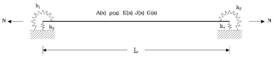
Figure 1.
General tie-rod structural model for tensile force dynamic identification approaches.
The simplest approach is the natural frequency-based method, developed starting from the taut string theory [33,35]: the tensile force N can be calculated from the n-th experimentally measured natural frequency by:
This method requires the knowledge of only one natural frequency, and, therefore, it appears suitable for reprocessing interferometric radar dynamic measurements. However, it is worth noting that it is based on the assumption that the tie-rod can be assimilated to a taut string, i.e., that the bending stiffness is negligible compared to the axial stiffness, and that the influence of the eventual sag is negligible. Consequently, the stiffness of the rotational springs at the ends is negligible on the tensile force determination: in short, the tie-rod is considered a simply supported beam with no bending stiffness. This strong simplification, of course, may yield substantial differences between the actual value of the tensile force and the value determined by (1).
A more advanced approach using only modal frequencies was proposed by Lagomarsino and Calderini in [14] expressly for the determination of the tensile force in the tie-rods of historical constructions. There, the considered structural model employed for the tie-rod is an Euler–Bernoulli beam subjected to a constant axial tensile force. Moreover, the beam is assumed to be spring-hinged at both ends with rotational elastic-springs having the same flexural stiffness k, i.e., k1 = k2 = k; both the translational constraints at the extremities are assumed to be perfect (see Figure 1).
By the separation of variables method, the governing partial differential equation describing the free transverse vibrations of the beam subject to the axial load N can be separated into two ordinary differential equations. A linear algebraic system can be obtained imposing the appropriate static and kinematic boundary conditions to the general solution of one of these two ordinary differential equations. This system has a non-trivial solution only if the determinant of the coefficient matrix of the system vanishes, that is, if the following equation is fulfilled:
where the tensile force appears inside α and β, being:
with ω the separation variable, representing the circular frequency of the part of the response function depending on the time.
The method consists of finding the unknown parameters EJ, k and N, which fulfill (2). Nevertheless, a general closed-form solution does not exist, unlike simple extreme cases. Therefore, numerical methods should be employed. To this aim, in [14], the following three parameters are introduced:
where represents an empirical reference value for the bending stiffness , (2) assumes the following a-dimensional form:
(3) becomes:
where n = 1, 2, …, and can be assumed as the exact solution for the first modal frequency evaluated in the ideal case of a “pinned–pinned beam” with bending stiffness :
(see [14] for details).
In general, the knowledge of three natural frequencies , n = 1, 2, …, is necessary for determining φ, γ and δ, related to the unknown parameters EJ, k and N. Specifically, a system of three nonlinear equations should be solved through numerical techniques. However, this procedure may be affected by significant instabilities; therefore, in [3], it is suggested to determine the three unknown parameters through the minimization of an error function G defined as follows:
where , i = 1,2,3. Furthermore, in [14], a suitable procedure for minimizing (8), performed through an international mathematics and statistics library (ISML) routine.
In short, the approach in [14] considers as input data for the tie-rod the length L, easily measurable in situ, and the density, and require an empirical assumption on the reference value for the bending stiffness, to be estimated through direct measurements of the tie-rod’s section and the quality of the steel. Then, it allows for identifying the tensile force N by experimentally determining three natural frequencies. This can be due to employing even only one accelerometer; the possibility of determining the tensile force without any information about mode shapes makes this approach suitable for reprocessing interferometric radar measurements.
Clearly, some of the simplifying assumptions of the model under examination may introduce errors on the estimated value of N: indeed, the geometrical and inertial parameters of the cross-section of the tie-rod, along with the density and the elastic moduli, are considered as constant, and the elastic rotational constraints at the ends are assumed to have the same stiffness. Finally, shear deformations are neglected. Nevertheless, such assumptions could usually be considered reasonable in the majority of practical applications. Moreover, the structural model is more representative than that employed in the natural frequency-based method and thus, in principle, capable of more accurate results.
3. Microwave Radar Interferometry for Structural Vibration Measurements
The radar interferometer is a coherent radar that allows detecting even small displacements of a target located at a great distance by generating, transmitting and receiving electromagnetic waves. The interferometric working principle allows measuring displacements by exploiting phase information of the back-reflected signal. The capability of remotely monitoring displacements of several points of a structure is the main advantage of this relatively new technology over other existing and well-established measurement techniques [43,44,45,46].
Furthermore, the time sampling of the acquired data makes the radar interferometer also capable of vibrations measurements. In the dynamic structural field, the most advantageous features of this technology are the possibility of remote, contactless measurements (in principle, the access to the construction is not needed), the quick and easy installation (about 15 min); the possibility of operating day and night and in all weather conditions.
Specifically, for the experimental tests described in the following Section, the employed interferometric radar system is a customized version of the IBIS-FS instrument, manufactured by IDS GeoRadar (Pisa, Italy) and aimed at remote static and dynamic monitoring of structures.
The system basically consists of:
- The radar unit, including the transmitter, the receiver, and the antennas, capable of generating, emitting, receiving, and processing modulated microwaves of a specified frequency. In particular, the two antennas on the front side focus the radiated energy in the form of a beam of a suitable shape during the transmission and collect the echo signal during the receiving phase. The unit includes the interferometric sensor and the communication ports.
- The power module. Two 12-volt batteries provide an independent power supply.
- The control and recording module. A portable field computer, USB connected to the radar units, and equipped with the IBIS-FS CONTROLLER custom software, is used to manage the tests and to monitor and record the acquired data.
- A sturdy tripod is provided with a movable head allowing the radar beam to be oriented in any direction.
The accurate detection of differential displacements of the targets included in the cone of view of the antennas is performed by exploiting the following principles:
- The stepped frequency–continuous wave (SF–CW) technique [34] allowing for a large bandwidth even using long-duration microwaves (continuous waves) by linearly increasing the frequency of successive pulses in discrete steps (stepped frequency). This principle enables the sensor to detect the displacements of several targets at different locations, given that they are in the scenario illuminated by the emitted beams and are spaced more than the spatial resolution of the instrument (0.50 m for IBIS-FS). An SF–CW radar achieves a large effective bandwidth through a burst of N electromagnetic pulses (tones), whose frequencies are increased from tone-to-tone by a constant frequency increment ∆f (see Figure 2, left). By taking the inverse discrete Fourier transform (IDFT) of the received complex signal sampled at N discrete frequencies, the response is reconstructed in the time domain of the radar, obtained the diagram called range profile (Figure 2, right), reporting the received echo intensity (amplitude) in the function of the distance of the target from the sensor. Peaks in the range profile diagram represent the locations of targets, reflecting a good quality signal.
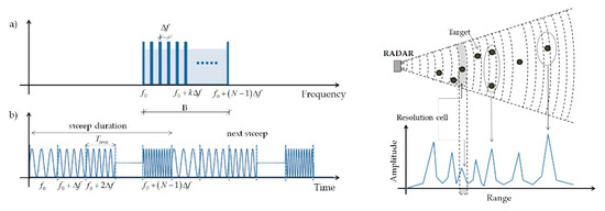 Figure 2. The SF-CW technique in (a) time and (b) frequency domain [34] (left) and the range profile diagram [41].
 - The radar interferometry technique: the electromagnetic waves reflected back by moving targets are characterized by a phase shift ∆φ compared to the emitted waves. This phase information can be exploited to detect differential radial displacements along the wave propagation direction. Indeed, radial displacements are proportional to the wave propagation velocity and to the phase shift ∆φ, and inversely proportional to the central frequency of the emitted waves [34].
The main features of the employed customized IBIS-FS radar interferometer are collected in Table 1.

Table 1.
Radar interferometer: features.
About data in Table 1, notice that the maximum allowed value of the sampling frequency of the standard IBIS-FS device is 200 Hz and that the displacement accuracy measured as line-of-sight displacement standard deviation depends on the distance between instrument and target and on the signal-to-noise ratio (SNR) of the received waves.
The interferometric radar technique is still under investigation and development with the aim of overcoming some relevant drawbacks. First, the maximum accuracy of displacement measurements, of the order of hundredths of millimeters, can be considered a good value, but as recalled above, this accuracy is achievable only in the presence of targets with good reflectivity on the structure and decreases with the distance. Second, as suggested by Figure 2, right, the observed scenario is detected from the radar interferometer as divided into discrete ranges (the so-called range bins) along the line-of-sight direction. As a consequence, the radar interferometer is not able to distinguish two or more reflective elements located at the same range bin, i.e., at the same radial distance from the instrument, since they correspond to the same peak in the range profile diagram. Third, the system can measure only the component of displacements along the line-of-sight direction. The same three considerations hold for dynamic measurements.
In conclusion, it is possible to say that a radar interferometer could provide high-precision measurements of the radial component of displacements but without accurate information about the location of the observed points. This, for example, prevents from determining e mode shapes of vibrating structures, unless they occur special conditions like, e.g., in the case of large structures with many well-spaced high reflectivity points: clearly, this is not the case of tie-rods of historic masonry constructions.
Anyway, to improve the accuracy of measurements also in the presence of targets with low reflectivity and/or for clearly distinguish measurement points on the structure, some corner reflectors can be installed. A corner reflector is a pyramidal metallic element with high reflectivity to electromagnetic waves. Even though this is an effective solution, the need to access the construction nullifies one of the main advantages of the interferometric radar technique. On the other hand, the installation of corner reflectors is easier and quicker than installing accelerometers.
The cited improvements of the experimental setup, along with the research activities performed to take advantage of the above recalled appealing features of the interferometric radar technique, are opening increasing application field for this experimental approach, also involving application to architectural heritage constructions [45,46,47].
4. Experimental Setup
The capability of the interferometric radar technique for application to the estimation of tensile force in tie-rods was tested in an experimental campaign carried out at Laboratory “M. Salvati” of the Polytechnic University of Bari.
To this aim, a suitable experimental device for applying known tensile forces in rods and cable was built (Figure 3) to reproduce the working conditions of a tie-rod like that employed in masonry constructions. In particular, this device consists of a supporting structure composed of 2 horizontal beams HEA 140 connected by two vertical high stiffness steel plates; a hydraulic jack and two clamping devices for tensioning the tie-rod; a load cell for directly measuring the real value of the tensile force applied. It is worth noticing that the experimental setup was assembled in such a way as to guarantee symmetric constraint conditions at the two ends of the tie-rod.
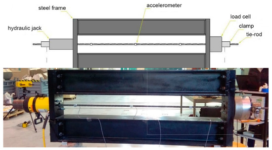
Figure 3.
The experimental device for applying known tensile forces to tie-rods.
As the tie-rod, a steel strand with geometric, inertial and mechanical parameters (equivalent circular cross-section) reported in Table 2 was employed for the experiments. In particular, three values of the tensile force were applied to the tie-rod: 50, 100 and 150 kN.
Table 2.
Geometric inertial and mechanical parameters of the tie-rod.
For each tensile force level, the vibrations of the steel tie-rod were measured simultaneously through both a radar interferometer and some accelerometers.
Specifically, the employed interferometric radar system is the customized version of the IBIS-FS manufactured by IDS GeoRadar (Pisa, Italy) described in Section 3. The sampling frequency employed for the tests was 297.62 Hz, the maximum distance between the instrument and the tie-rod was 10 m, and the IBIS-ANT5-H12V39 antennas were employed, having a power gain of 18 dBi, and a beamwidth at −3 dB of 12° in the azimuthal direction and of 39° in the elevation direction. This kind of antennas is one of the most directional available, capable of concentrating the beam at a restricted solid angle.
Indeed, to obtain good quality data, the length of the portion of the tie-rod falling into a single range bin should be minimized. On the other hand, there is the need to make as much as possible parallel the radial direction defined by the axis of radar antennas and the direction of transverse displacements of the tie-rod. Therefore, the relative position between the radar and the tie-rod was accurately studied before performing the tests and set in such a way as to be a right balance between the above two requirements, as described by Figure 4a.
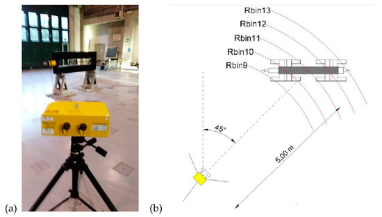
Figure 4.
The relative position between the radar interferometer and the tie-rod (a) and the range bins where the tie-rod falls (b).
Moreover, three uniaxial accelerometers were installed at 1/4, 1/2 and 3/4 of the tie-rod length (see Figure 3) oriented such that only transverse vibrations in the horizontal plane were measured. The featuresof the accelerometers are reported in Table 3. The acquisition and preprocessing of accelerometric data have been performed by a data acquisition system HBM MGCplus.
Table 3.
Accelerometers: features.
Vibrations of the tie-rod were excited by lightly striking it with an impact hammer. Notice that the intensity of the impulse was maintained very low to avoid damaging the accelerometers, but if only interferometric radar tests are made, it is possible to hit the tie-rod with much more energy, thus enhancing the amplitude of the vibrations and, therefore, the accuracy of the measurements.
A preliminary check clearly showed that interferometric radar data were inconsistent with the oscillating behavior of the cable put in vibration acquired by the accelerometers. This inconsistency is ascribable to the facts that the tests were performed in a closed space (as in practical applications on tie-rods of historic constructions) and that the supporting structure around the steel tie-rod, highly reflective since the corners of the steel frame, reflects signal that overshadows the reflection coming from the tie-rod. As a result, the radar was mainly measuring parasitic signals. Notice that another possible issue with interferometric radar measurements is that eventual vibrations of the instrument could affect the accuracy of the results since the instrument cannot discern between vibrations of the target structure and vibrations of its support [46]. Anyway, in the presented experiment it can be excluded the occurrence of this parasite effect since the test was performed in the indoor environment of the laboratory test hall, and the radar interferometer was firmly placed on the very stiff laboratory test hall floor.
To solve this problem, a corner reflector was installed on the tie-rod located to the left of the midpoint of the tie-rod at a distance of 8 cm; in Figure 4a is visible in the foreground the radar interferometer and in the background the experimental device for tensioning the tie-rod, housing the tie-rod equipped with the corner reflector. Moreover, the geometrical sketch in Figure 4b shows that the relative position between the radar interferometer and the experimental device is such that different sections of the tie-rod fall into different range bins.
A subsequent test showed that the installation of the corner reflector was effective for acquiring signals really coming from the vibrating tie-rod by the radar interferometer. Indeed, at this point, the frequency domain analysis of accelerometric and interferometric radar data was comparable (see Figure 5, referring to 50 kN applied tensile force). Notice that interferometric radar and accelerometric data were compared in the frequency domain because the locations of the corner reflector on the tie-rod were not coincident with the location of any accelerometer. Moreover, it is worth noting that interferometric radar data (Figure 5, above) are affected by much more noise compared to accelerometric data (Figure 5, below).

Figure 5.
Comparison between the radar (above) and the accelerometric (below) power spectral density (PSD) in the presence of a corner reflector. Applied tensile force: 50 kN.
5. Estimation of Tensile Force Starting from Vibration Data
5.1. Modified Lagomarsini and Calderini Approach
As discussed in Section 2, a suitable tensile force dynamic identification approach suitable for reprocessing interferometric radar data is that by Lagomarsino and Calderini [14]. Anyway, to have representative results, interferometric radar measurements required installing a corner reflector representing a non-negligible additional mass for the tie-rod, thus affecting the modal parameters of the tie-rod. In particular, the mass of the corner reflector, 1.5 kg, was about 30% of the mass of the tie-rod. Notice that, on the other hand, the mass of the accelerometers is negligible compared to the mass of the tie-rod (see Table 2).
To also consider the additional mass of the corner reflector in the structural model, the dynamic equations in [14] were expressly modified. First, the corner reflector was modeled (Figure 6) as a lumped mass located at the point of the tie-rod where it is installed. Then, the domain representing the beam was divided into two parts at the location of the lumped mass, and two different form functions describing the spatial variation of transverse displacement of the beam were introduced (the time dependence, instead, is described by the same function for the two parts of the beam):
where l is the distance of the concentered mass from the left end of the beam and C1, …, C8 are unknown constants, to be determined by imposing the boundary conditions as in the original approach, and the continuity conditions in correspondence of the section where the additional mass of the corner reflector is attached:
with γ defined in (4), and the continuity conditions:
with γ and δ defined in (4) and defined in (7). For writing (10) and (11), the rotational inertia of the corner reflector was neglected, considering it as a concentered mass.
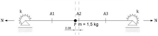
Figure 6.
Modified structural model with a lumped mass.
Now it becomes possible to write the linear algebraic system determining the 8 unknown constants C1, …, C8. In this case, as for the original method in Section 2, for determining a non-trivial solution, the coefficient matrix of the system must vanish, yielding to a characteristic equation similar to (2), here omitted for the sake of brevity. Finally, the unknown parameters EJ, k and N can be determined by a numerical procedure based on minimizing the same error function G in (8). Therefore, the problem of the beam supporting a concentrated mass can be handled with the same numerical solution approach proposed in [14] by introducing the same parameters described in Section 2.
5.2. Experimental Identification of Natural Frequencies
For the modal identification process, interferometric radar data were processed by using the custom IBIS software; in particular, the peak picking method [48] was applied based on the power density spectrum; therefore, only natural frequencies were estimated. In Table 4, the first three natural frequencies fr estimated in the presence of the corner reflector starting from interferometric radar data are reported for an applied tensile force of 50 KN. For the sake of the comparison, also the first three natural frequencies fa estimated in the presence of the corner reflector starting from accelerometric data are reported in the same table. In the latter case, the frequencies were determined by performing frequency domain decomposition (FDD) [49,50] through a MATLAB routine [51]. Notice that it was impossible to apply the more accurate FDD approach to interferometric radar data since, for FDD, information on multiple measurement points is needed, whereas the only usable information acquired by the radar interferometer is that of the measurement point where the corner reflector was installed.
Table 4.
Natural frequencies are experimentally determined starting from interferometric radar data (fr) and accelerometric data (fa). Applied tensile force: 50 kN.
Table 5 and Table 6 reported both the first three natural frequencies fr and fa determined starting from interferometric radar and accelerometric data, for the tie-rod with installed the corner reflector, and for a known tensile force of 100 kN (Table 5) and 150 kN (Table 6).
Table 5.
Natural frequencies experimentally determined starting from interferometric radar data (fr) and accelerometric data (fa). Applied tensile force: 100 kN.
Table 6.
Natural frequencies experimentally determined starting from interferometric radar data (fr) and accelerometric data (fa). Applied tensile force: 150 kN.
Table 4, Table 5 and Table 6 also reported the relative differences between the interferometric radar and accelerometric determined frequency. It is easily seen that the mean value of the frequency discrepancy between interferometric radar and accelerometric data is 0.246%, and its maximum value is 1.187%. This validates the interferometric radar technique and shows that if referring to tensile force estimation approaches, which require only the knowledge of natural frequencies, interferometric radar measurements can be considered equivalent to accelerometric measurements. Of course, this equivalence holds when the corner reflector is installed. Another comment concerns the impossibility of identifying the frequency of the third mode from interferometric radar measurements: this is because this frequency is more than double the employed sampling frequency and thus is inaccessible to the device. Anyway, in practical applications, the tie-rods installed in historic construction are usually characterized from lower frequencies compared to that in Table 6, and therefore, the above-described issue of the radar interferometer does not constitute an actual limit.
5.3. Estimation of the Tensile Force
Now, starting from the experimentally estimated frequency, it is possible to apply the modified version of the approach by Lagomarsini and Calderini described in Section 5.1 to determine the dynamically identified tensile forces to be compared to the known ones to verify the accuracy of the procedure under investigation.
Calculations were performed through an expressly written MATLAB code; in particular, the required constrained minimization of the error function (8) was performed by using the MATLAB function fmincon. The minimization domain was constructed by assigning as lower limits a bending stiffness , corresponding to a taut string behavior, and rotational stiffness of the constraints at the ends of the beam kinf = 0; accordingly, in view of (1) an upper bound of the tensile force determined by the first natural frequency f1 is:
For the upper limit of the domain, a flexural stiffness increased by 30% over the assumed reference value of the bending stiffness , that is, , was considered. Moreover, a rotational stiffness of the constraints at the ends of the beam , practically corresponding to a perfectly clamped constraint. In this case, a closed-form solution for the relationship between the first natural frequency f1 and the tensile force N is, after some analytical developments:
Solving (13) for determining N, it is possible to determine a lower bound for the tensile force . In Table 7, the range variation considered for the tensile force N and for the parameters γ and δ in (4) is summarized.
Table 7.
Ranges for the variables of the minimization problem.
Notice, in passing, that the column of Table 7 containing the upper bound of the tensile force Nsup allows for appreciating the error in determining the tensile force coming from applying the basic natural frequency-based method (considering the first natural frequency). It is easily seen that this error is quite large, ranging from 12.3% (applied tensile force 150 kN) to 55.8% (applied tensile force 50 kN).
In what follows, tensile forces estimated starting from interferometric radar determined frequencies are compared to those estimated starting from accelerometric determined frequencies.
Figure 7 (left) shows the three-dimensional plot of the objective function G in (8) as a function of the variables N and γ, for fixed δ = 1; a representation of the values of G in false color scale in the plane N-γ, also for δ = 1, is represented in Figure 7 (right). In both cases, the evaluations are based on dynamic data acquired by radar interferometry for applied tensile force 50 kN. Similarly, starting again from the same experimental data, Figure 8 (left) shows the three-dimensional plot of G as a function of the variables γ and δ, for fixed N = 50 kN; a representation of the values of G in false color scale in the plane γ-δ, also for N = 50 kN, is given in Figure 8 (right).
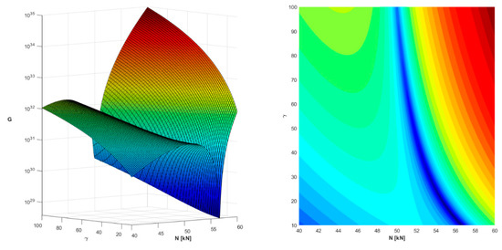
Figure 7.
Plots of the objective function G as a function of the variables N and γ (for fixed δ = 1). Dynamic data acquired by radar interferometry for applied tensile force 50 kN.
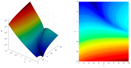
Figure 8.
Plots of the objective function G as a function of the variables γ and δ (for fixed N = 50 kN). Dynamic data acquired by radar interferometry for applied tensile force 50 kN.
To minimize the objective function G, the same practical tricks discussed in [14] were adopted. In particular, for fast convergence of the optimization algorithm, a good initial estimate of the unknown variables, as the starting point for the numerical calculations, is needed. These estimates can be determined based on in situ measurements on the tie-rod and, eventually, by numerical simulations performed by FEM.
The final results in terms of the estimated tensile force are reported in Table 8. In particular, for each (known) value of the applied tensile force indicated in the table as Na, the corresponding value Ne estimated starting from interferometric radar measurements by applying the modified Lagomarsino and Calderini approach is indicated. The percentage error between actual and estimated tensile force is also reported: the error is quite low, with a maximum value of 2.42%, which is a very good result for practical applications. It is worth noting that in the case of Na = 150 kN, as recalled above, it was not possible to determine the frequency of the third mode starting from interferometric radar data. However, since interferometric radar estimated frequencies are practically the same as those determined from accelerometric data, the minimization of G was performed by considering as the frequency of the third mode ω3 = 151.753 Hz obtained starting from accelerometric measurements.
Table 8.
Applied and estimated tensile force, with percentage error.
6. Conclusions
Monitoring tensile force in tie-rods over time is of great importance for the structural safety of historical masonry constructions. Among the experimental methods available, the dynamic methods appear as the most suitable. However, dynamic tests may be time-expensive, technically complex and require full access to the tie-rod. To overcome these drawbacks, here, the effectiveness of the interferometric radar technique for vibration measurements was studied by performing laboratory tests on a tie-rod under known tensile forces.
Indeed, radar interferometry is a quick and easy to install technique allowing for remote displacement and vibration measurements . Nevertheless, at the present level of development with radar interferometry is very difficult to determine mode shapes. As a consequence, this measurement technique should be complemented by a dynamic identification approach for the tensile force in tie-rod based only on frequency data. In particular, the approach by Lagomarsino and Calderini in [14] was considered.
Laboratory tests indicated that for obtaining good quality data in interferometric radar measurements, it was necessary to install a corner reflector on the tie-rod. To take into account the not-negligible mass of the corner reflector, the theoretical approach in [14] was accordingly modified.
From the results reported in Section 5.3, the following considerations can be drawn.
First, Table 4, Table 5 and Table 6 clearly indicate that provided a corner reflector is installed of the tie-rod, interferometric radar data yield to a determination of the natural frequencies practically coincident with that evaluated by employing three accelerometers and the more sophisticated FDD approach. Therefore, the radar interferometer is actually capable of gathering the vibration data needed for applying tensile force identification approaches based only on the knowledge of the natural frequency of the tie-rod.
Second, for what concerns the method for determining the tensile force starting from frequency data, the simple natural frequency-based Method, where the flexural stiffness of the tie-rod is neglected, leads to too large error for the demands of practical applications (see Table 7). On the other hand, by employing the modified version of the approach by Lagomarsino and Calderini, here proposed, very accurate results can be obtained, with a mean value of the error in the determination of the tensile force of 1.85%, with and a maximum value 2.42% (see Table 8).
In addition, the obtained results show that the above-recalled dynamic identification approach for the tensile force is suitable for practical applications.
To this aim, it is worth noting that to date, the sampling frequency of standard radar interferometers is limited to 200 Hz: this, in view of Nyquist’s theorem [52], obstructs the possibility of measuring vibration frequencies higher than 100 Hz since the aliasing phenomena. Anyway, in practical applications, the bending stiffness, the length, and the tensile force of tie-rods are such that the above-recalled limitation is not relevant (only for thick tie-rods with high tensile forces such high frequencies are expected).
In conclusion, these considerations suggest that the modified version of the approach by Lagomarsino and Calderini applied to interferometric radar data acquired in the presence of a corner reflector installed to the tie-rods leads to accurate and reliable results, matching the needs of practical applications.
Anyway, the need for the corner reflector in some sense obstructs the advantages of using radar interferometry since it is necessary to access the tie-rod, even if the installation of the corner reflector is faster and easier than that of accelerometers and of the required wiring. Future development of the present research will concern a real historic structure; one of the points of attention will be the possibility of obtaining meaningful dynamic data through the radar interferometer without installing corner reflectors. Indeed, in the laboratory tests described in this paper, the tie-rod was surrounded by a high reflective steel frame, whereas in real structures, the reflectivity of the obstacles surrounding the tie-rod could be much lower. Moreover, limited access to the tie-rod is needed in any case since it is necessary to excite vibrations by an impact hammer.
Another issue for the approach proposed here may arise from the presence of markedly different constraint conditions at the ends of the tie-rods. Indeed, the approach in [14] assumes that the tie-rod can be modeled as a spring-hinged beam with the same flexural stiffness k of the rotational elastic springs. In these cases, it is necessary to study further advancements of the dynamic identification approach in [14] or to refer to another dynamic identification approach based only on frequency data. In addition, the implementation of the shear deformability in the structural model may be a suitable advancement of the dynamic identification approach for improving the accuracy in the determination of the tensile force, especially in some particular conditions.
Author Contributions
Conceptualization and methodology, A.C., A.F. and M.D.P.; software and validation G.M.; investigation, A.C. and G.M.; resources, M.D.P.; writing—original draft preparation, D.C.; writing—review and editing, A.F. All authors have read and agreed to the published version of the manuscript.
Funding
This research received no external funding.
Data Availability Statement
Data sharing not applicable.
Conflicts of Interest
The authors declare no conflict of interest.
References
- Binda, L.; Saisi, A.; Tiraboschi, C. Investigation procedures for the diagnosis of historic masonries. Constr. Build. Mater. 2000, 14, 199–233. [Google Scholar] [CrossRef]
- Camassa, D.; Castellano, A.; Fraddosio, A.; Piccioni, M.D. A New Ultrasonic Amplitude Tomography Approach, with Validation on Masonry Tuff Blocks. J. Nondestruct. Eval. 2020, 39, 49. [Google Scholar] [CrossRef]
- Ivorra, S.; Camassa, D.; Bru, D.; Gisbert, I.; Castellano, A.; Fraddosio, A.; Piccioni, M.D. Assessment of the TRM reinforcement of windowed masonry walls through OMA identification. In Proceedings of the 11th International Conference on Structural Dynamics, EURODYN 2020, Virtual, Athens, Greece, 23–26 November 2020; Volume 1, pp. 2377–2385. [Google Scholar]
- Scacco, J.; Milani, G.; Bove, M.; Castellano, A.; Fraddosio, A.; Piccioni, M.D. Experimental and numerical analysis of the effectiveness of FRCM strengthening on a parabolic tuff barrel vault. In Proceedings of the AIP Conference Proceedings, International Conference of Computational Methods in Sciences and Engineering 2019, ICCMSE 2019, Rhodes, Greece, 1–5 May 2019; Volume 2186, p. 100005. [Google Scholar]
- Mora-Gómez, J. Historical Iron Tie-rods In Vaulted Structures: Parametrical Study Through A Scaled Model. WIT Trans. Built Environ. 2015, 153, 669–680. [Google Scholar]
- Calderini, C.; Lagomarsino, S. Seismic response of masonry arches reinforced by tie-rods: Static tests on a scale model. J. Struct. Eng. 2015, 141, 4014137. [Google Scholar] [CrossRef]
- Podestà, S.; Scandolo, L. Earthquakes and Tie-Rods: Assessment, Design, and Ductility Issues. Int. J. Arch. Herit. 2019, 13, 329–339. [Google Scholar] [CrossRef]
- Ural, A.; Fırat, F.K.; Tuğrulelçi, Ş.; Kara, M.E. Experimental and numerical study on effectiveness of various tie-rod systems in brick arches. Eng. Struct. 2016, 110, 209–221. [Google Scholar] [CrossRef]
- Calderini, C.; Piccardo, P.; Vecchiattini, R. Experimental Characterization of Ancient Metal Tie-Rods in Historic Masonry Buildings. Int. J. Arch. Herit. 2019, 13, 416–428. [Google Scholar] [CrossRef]
- Ricci, E.; Fraddosio, A.; Piccioni, M.D.; Sacco, E. A new numerical approach for determining optimal thrust curves of masonry arches. Eur. J. Mech. A Solids 2019, 75, 426–442. [Google Scholar] [CrossRef]
- Fraddosio, A.; Lepore, N.; Piccioni, M.D. Thrust Surface Method: An innovative approach for the three-dimensional lower bound Limit Analysis of masonry vaults Eng. Struct. 2020, 202, 109846. [Google Scholar] [CrossRef]
- Briccoli Bati, S.; Tonietti, U. Experimental methods for estimating in situ tensile force in tie-rods. J. Eng. Mech. 2001, 127, 1275–1283. [Google Scholar] [CrossRef]
- Tullini, N.; Rebecchi, G.; Laudiero, F. Bending tests to estimate the axial force in tie-rods. Mech. Res. Commun. 2012, 44, 57–64. [Google Scholar] [CrossRef]
- Lagomarsino, S.; Calderini, C. The dynamical identification of the tensile force in ancient tie-rods. Eng. Struct. 2005, 27, 846–856. [Google Scholar] [CrossRef]
- Tullini, N.; Laudiero, F. Dynamic identification of beam axial loads using one flexural mode shape. J. Sound Vib. 2008, 318, 131–147. [Google Scholar] [CrossRef]
- Amabili, M.; Carra, S.; Collini, L.; Garziera, R.; Panno, A. Estimation of tensile force in tie-rods using a frequency-based identification method. J. Sound Vib. 2010, 329, 2057–2067. [Google Scholar] [CrossRef]
- Li, S.; Reynders, E.; Maes, K.; De Roeck, G. Vibration-based estimation of axial force for a beam member with uncertain boundary conditions. J. Sound Vib. 2013, 332, 795–806. [Google Scholar] [CrossRef]
- Maes, K.; Peeters, J.; Reynders, E.; Lombaert, G.; De Roeck, G. Identification of axial forces in beam members by local vibration measurements. J. Sound Vib. 2013, 332, 5417–5432. [Google Scholar] [CrossRef]
- Sorace, S. Parameter models for estimating in-situ tensile force in tie-rods. J. Eng. Mech. 1996, 122, 818–825. [Google Scholar] [CrossRef]
- Brincker, R.; Ventura, C.E. Introduction to Operational Modal Analysis; John Wiley & Sons, Ltd, Chichester: West Sussex, UK, 2015. [Google Scholar]
- Rainieri, C.; Fabbrocino, G. Operational Modal Analysis of Civil Engineering Structures; Springer: New York, NY, USA, 2014. [Google Scholar]
- Ewins, D.J. Modal Testing: Theory, Practice and Application, 2nd ed.; Research Study Press: Philadelphia, PA, USA, 2000. [Google Scholar]
- Campagnari, S.; di Matteo, F.; Manzoni, S.; Scaccabarozzi, M.; Vanali, M. Estimation of Axial Load in Tie-Rods Using Experimental and Operational Modal Analysis. J. Vib. Acoust. 2017, 139, 041005. [Google Scholar] [CrossRef]
- Cescatti, E.; Da Porto, F.; Modena, C. Axial Force Estimation in Historical Metal Tie-Rods: Methods, Influencing Parameters, and Laboratory Tests. Int. J. Arch. Herit. 2019, 13, 317–328. [Google Scholar] [CrossRef]
- Tullini, N.; Rebecchi, G.; Laudiero, F. Reliability of the Tensile Force Identification in Ancient Tie-Rods Using One Flexural Mode Shape. Int. J. Arch. Herit. 2019, 13, 402–410. [Google Scholar] [CrossRef]
- Duvnjak, I.; Ereiz, S.; Damjanović, D.; Bartolac, M. Determination of Axial Force in Tie Rods of Historical Buildings Using the Model-Updating Technique. Appl. Sci. 2020, 10, 6036. [Google Scholar] [CrossRef]
- Rainieri, C.; Aenlle, M.L. The influence of parameter estimation error on the accuracy of a vibration based tensile load estimation technique. In Proceedings of the ISMA 2016—International Conference on Noise and Vibration Engineering and USD2016—International Conference on Uncertainty in Structural Dynamics, Leuven, Belgium, 19–21 September 2016; pp. 1697–1710. [Google Scholar]
- Gentilini, C.; Marzani, A.; Mazzotti, M. Nondestructive characterization of tie-rods by means of dynamic testing, added masses and genetic algorithms. J. Sound Vib. 2013, 332, 76–101. [Google Scholar] [CrossRef]
- Collini, L.; Garziera, R.; Riabova, K. Vibration Analysis for Monitoring of Ancient Tie-Rods. Shock Vib. 2017, 2017, 7591749. [Google Scholar] [CrossRef]
- Coïsson, E.; Collini, L.; Ferrari, L.; Garziera, R.; Riabova, K. Dynamical Assessment of the Work Conditions of Reinforcement Tie-Rods in Historical Masonry Structures. Int. J. Arch. Herit. 2019, 13, 358–370. [Google Scholar] [CrossRef]
- Garziera, R.; Amabili, M.; Collini, L. A hybrid method for the nondestructive evaluation of the axial load in structural tie-rods. Nondestruct. Test. Eval. 2011, 26, 197–208. [Google Scholar] [CrossRef]
- Gentile, C.; Poggi, C.; Ruccolo, A.; Vasic, M. Vibration-Based Assessment of the Tensile Force in the Tie-Rods of the Milan Cathedral. Int. J. Arch. Herit. 2019, 13, 402–415. [Google Scholar] [CrossRef]
- Gentile, C. Application of microwave remote sensing to dynamic testing of stay-cables. Remote Sens. 2010, 2, 36–51. [Google Scholar] [CrossRef]
- Gentile, C.; Cabboi, A. Vibration-based Structural Health Monitoring of stay cables by microwave remote sensing. Smart Struct. Syst. 2015, 16, 263–280. [Google Scholar] [CrossRef]
- Schmieder, M.; Taylor-Noonan, A.; Heere, R. Rapid non-contact tension force measurements on stay cables. Bridge Maintenance, Safety, Management, Resilience and Sustainability. In Proceedings of the Sixth International Conference on Bridge Maintenance, Safety and Management (IABMAS 2012), Stresa, Lake Maggiore, Italy, 8–12 July 2012; pp. 3799–3805. [Google Scholar]
- Yan, B.; Chen, W.; Yu, J.; Jiang, X. Mode shape-aided tension force estimation of cable with arbitrary boundary conditions. J. Sound Vib. 2019, 440, 315–331. [Google Scholar] [CrossRef]
- Resta, C.; Chellini, G.; Falco, A.D. Dynamic Assessment of Axial Load in Tie-Rods by Means of Acoustic Measurements. Buildings 2020, 10, 23. [Google Scholar] [CrossRef]
- Gioffré, M.; Cavalagli, N.; Pepi, C.; Trequattrini, M. Laser doppler and radar interferometer for contactless measurements on unaccessible tie-rods on monumental buildings: Santa Maria della Consolazione Temple in Todi. J. Phys. Conf. Ser. 2017, 778, 012008. [Google Scholar] [CrossRef]
- Pieraccini, M.; Fratini, M.; Parrini, F.; Macaluso, G.; Atzeni, C. High-speed CW step-frequency coherent radar for dynamic monitoring of civil engineering structures. Electron. Lett. 2004, 40, 907–908. [Google Scholar] [CrossRef]
- Pieraccini, M.; Parrini, F.; Fratini, M.; Atzeni, C.; Spinelli, P.; Micheloni, M. Static and dynamic testing of bridges through microwave interferometry. NDT E Int. 2007, 40, 208–214. [Google Scholar] [CrossRef]
- Pieraccini, M. Monitoring of civil infrastructures by interferometric radar: A review. Sci. World J. 2013, 2013, 786961. [Google Scholar] [CrossRef] [PubMed]
- Pieraccini, M.; Fratini, M.; Parrini, F.; Atzeni, C.; Bartoli, G. Interferometric radar vs. accelerometer for dynamic monitoring of large structures: An experimental comparison. NDT E Int. 2008, 41, 258–264. [Google Scholar] [CrossRef]
- Pieraccini, M.; Fratini, M.; Parrini, F.; Pinelli, G.; Atzeni, C. Dynamic survey of architectural heritage by high-speed microwave interferometry. IEEE Geosci. Remote. Sens. Lett. 2005, 2, 28–30. [Google Scholar] [CrossRef]
- Gentile, C.; Bernardini, G. An interferometric radar for non-contact measurement of deflections on civil engineering structures: Laboratory and full-scale tests. Struct. Infrastruct. Eng. 2009, 6, 521–534. [Google Scholar] [CrossRef]
- Gentile, C.; Saisi, A. Dynamic Testing of Masonry Towers Using the Microwave Interferometry. Key Eng. Mater. 2014, 628, 198–203. [Google Scholar] [CrossRef]
- Castellano, A.; Fraddosio, A.; Martorano, F.; Mininno, G.; Paparella, F.; Piccioni, M.D. Structural health monitoring of a historic masonry bell tower by radar interferometric measurements. In Proceedings of the 2018 IEEE Workshop on Environmental, Energy, and Structural Monitoring Systems, EESMS 2018, Salerno, Italy, 21–22 June 2018; pp. 1–6. [Google Scholar]
- Castellano, A.; Fraddosio, A.; Scacco, J.; Milani, G.; Piccioni, M.D. Dynamic Identification of the Damage for a Parabolic Tuff Barrel Vault with Differential Settlements of the Supports. In Proceedings of the 2020 IMEKO TC-4 International Conference on Metrology for Archaeology and Cultural Heritage, Trento, Italy, 22–24 October 2020; pp. 123–128. [Google Scholar]
- Felber, A.J. Development of a Hybrid Bridge Evaluation System. Ph.D. Thesis, University of British Columbia, Vancouver, BC, Canada, 1993. [Google Scholar]
- Brincker, R.; Zhang, L.; Andersen, P. Modal Identification from Ambient Responses using Frequency Domain Decomposition. In Proceedings of the 18th International Modal Analysis Conference—IMAC, San Antonio, TX, USA, 7–10 February 2000; Volume 1, pp. 625–630. [Google Scholar]
- Brincker, R.; Zhang, L.; Andersen, P. Modal identification of output-only systems using frequency domain decomposition. Smart Mater. Struct. 2001, 10, 441–445. [Google Scholar] [CrossRef]
- Farshchin, M. Frequency Domain Decomposition (FDD). MATLAB Repos. 2015. Available online: www.mathworks.com/matlabcentral/fileexchange/50988-frequency-domain-decomposition-fdd (accessed on 19 April 2021).
- Shannon, C.E. Communication in the Presence of Noise. Proc. IRE 1949, 37, 10–21. [Google Scholar] [CrossRef]


Publisher’s Note: MDPI stays neutral with regard to jurisdictional claims in published maps and institutional affiliations. |
© 2021 by the authors. Licensee MDPI, Basel, Switzerland. This article is an open access article distributed under the terms and conditions of the Creative Commons Attribution (CC BY) license (https://creativecommons.org/licenses/by/4.0/).