1. Introduction
The Small-K Advanced DIffractometer (SKADI, for the naming we exploited the correspondence between the reciprocal space vector
and momentum transfer vector
) is a joint in-kind project of French (LLB) and German (FZ Jülich) partners to deliver a Small-Angle Neutron Scattering (SANS) instrument to the European Spallation Source (ESS) [
1,
2]. The originally proposed instrument is described in a previous publication [
3]. This manuscript details the further developments of SKADI, highlighting the final changes at the beginning of the construction phase. In addition, further practical requirements for performing experiments, such as sample area and environment, will be considered. Here, we want to highlight the extensive collaboration with user groups in order to develop state-of-the art sample environments [
4,
5,
6].
Small-Angle Neutron Scattering (SANS) instruments scatter neutrons from samples at angles usually below 0.3 rad and above some tenth of a mrad. Combined with cold neutrons at wavelengths above ∼3 Å this results in an accessible inverse space of and a corresponding size range in real space in the sample between several Angstroms and a micrometer. The spatial resolution at the detector, the wavelength resolution of the detected neutrons, the brilliance transfer of useful neutrons to the sample, the simultaneously covered solid angle with the detector, as well as the general suitability for a wide range of experiments are important parameters during the design of such an instrument.
While the spatial resolution of the detector itself is given by the employed detector technology, the positioning of the detector can be used to adjust the solid angle coverage of a pixel or the readout mode [
7] to achieve the desired resolution. For most experimental settings, the detector resolution of SKADI is better than needed in order to avoid an additional contribution to the overall resolution. Thus, for example, for a central detector setting (sample-detector distance equals the collimation length), an ideal mapping of the sample aperture would lead to a pixel size identical to that of the generally used sample aperture (
mm
), while the chosen pixel resolution is
mm
. On the other hand, for the shorter detector position of the front detector, this still improves the resolution.
The wavelength resolution of the instrument is mainly determined by the rejection of unwanted neutrons in a selector or, as is the case with SKADI, by the time discrimination of arriving neutron pulses with a spread of kinetic energy and a time-of-flight readout of the detector.
In order to transfer the highest amount of neutrons per second, solid angle, angular divergence, and time, i.e., brilliance, to the sample the complete instrument has to be considered, since any component that is influencing the flow of neutrons can also absorb or deflect them. Special focus, in this case, has to be given to the extraction of neutrons from the moderator in order to maximize the brilliance transfer while avoiding a direct line of sight between sample and moderator to minimize unwanted background, for example, from -radiation.
The general feasibility for different experiments is again a holistic issue concerning all components of the instrument. The instrument needs to facilitate large, unconventional, or custom made sample environments, delivering the correct choice of resolution for the experiment at hand, while performing it in a timely manner. The control software needs to allow to adjust the experimentally relevant parameters, while allowing a good overview of everything that is happening at the same time and not distract the user from the experiment at hand. For SKADI, in fact, the whole instrument suite of ESS, NICOS [
8] as a control software was chosen, and the appropriate requirements are being implemented. The data will be recorded in event-mode, i.e.,with a time-stamp for each single neutron event on the detector. This will allow for cross-referencing additional settings of motor positions or sample environments to a specific neutron event. Finally, the data that will be provided to the user need to be in a format that facilitates the work flow of data analysis.
The description will treat the components following the path of the neutrons from the moderator to the detector in order to give a full overview of SKADI in a comprehensive manner. All of the simulations shown here have been carried out using the McStas framework [
9].
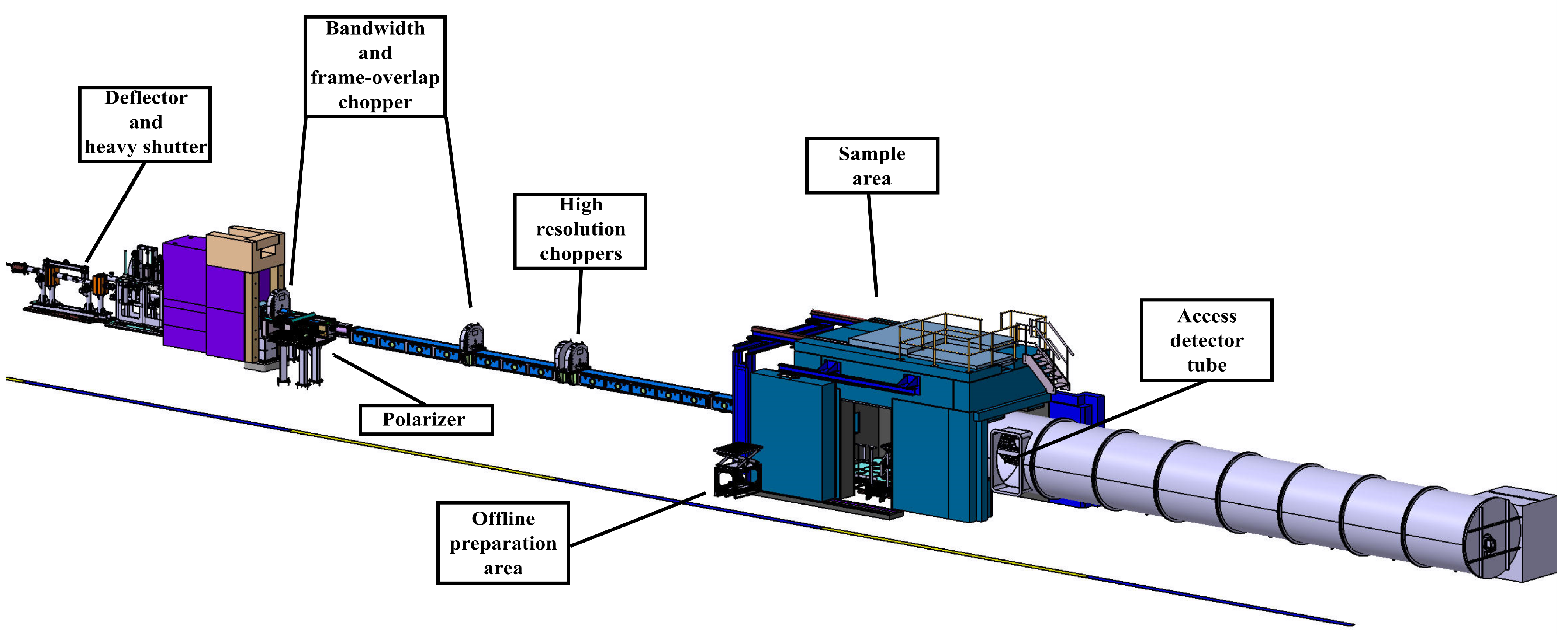
2. Overview
Figure 1 and
Table 1 give an overview of the SKADI instrument. The different components are described in sequence of the neutron flux from the neutron extraction up until the detector. There is a dedicated section for each of the described components.
2.1. Neutron Extraction
The neutron extraction is responsible for avoiding a direct line of sight between the moderator and the sample while transporting the highest brilliance possible. The two main considerations making this out of line of sight requirement necessary are radiation protection and signal to noise ratio. In the moderator area there is a high flux of particles other than neutrons, from the spallation process, and virtually any particle possible created by bremsstrahlung for which the accelerator provides enough energy. In addition to that, there is approximately one per neutron and high energy radiation may produce photo neutrons. Indeed, the signal to noise ratio with direct view of the moderator would be poor due to those additional particles. Existing detector technologies can hardly discriminate between that many different particles at such high flux rates. Even neglecting the necessity of having a clean spectrum at the sample and detector position, most of these particles would require higher shielding efforts when compared to cold or thermal neutrons. This is even more the case for an instrument like SKADI, which only requires the cold flux from the moderator at very low divergencies. Furthermore, reducing the total flux of particles, the requirements on shielding are considerably more moderate.
For cold neutrons, there are, in general, three approaches to that problem: (1) curved neutron guides (benders), (2) doglegs, and (3) deflectors. In the case of the curved neutron guides, channeled benders should also be considered. In order to transport the highest brilliance, and not merely the highest flux with highly diverging neutrons, it is a good approach to transport the ideal image of a fraction of the moderator equal to the cross section of the last defining aperture before the sample aperture. Higher divergent neutrons could possibly be transported, however would only be collimated away in the later parts of the instrument and increase shielding effort, while all of the neutrons as described before, can be used for the scattering experiment. In addition to that function, fast neutrons should be removed in the neutron extraction, which is usually happening as a by-product, since fast neutrons will not be affected by most of the optical components and, thus, propagate on a straight path.
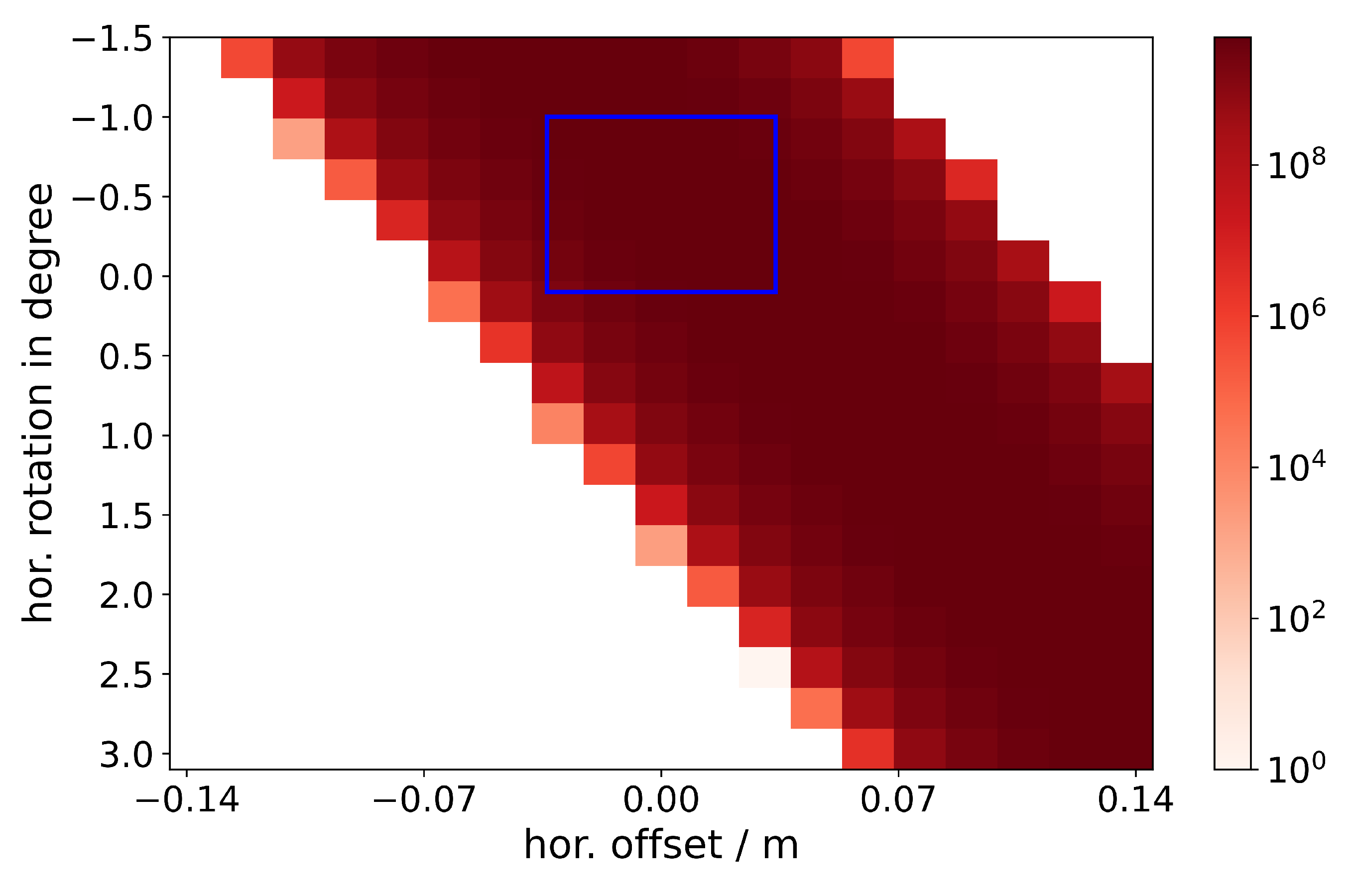
Thus, the first issue is finding the optimal view of the moderator in terms of flux and spectrum.
Figure 2 shows an image of integrated intensity of useful neutrons at the deflector exit vs. horizontal angle and horizontal shift of the neutron extraction system along the inside of the monolith. A diagonal line of optimal flux is found because the moderator has a preferred direction in which the neutrons are transmitted. Pairing this with the geometrical restrictions of the monolith insert a preferred window of installation is found. Using this, we chose to position the optical axis of SKADI at the coordinates of
and
mm. That is fairly central in the possible window and close to the central region of the high intensity ridge.
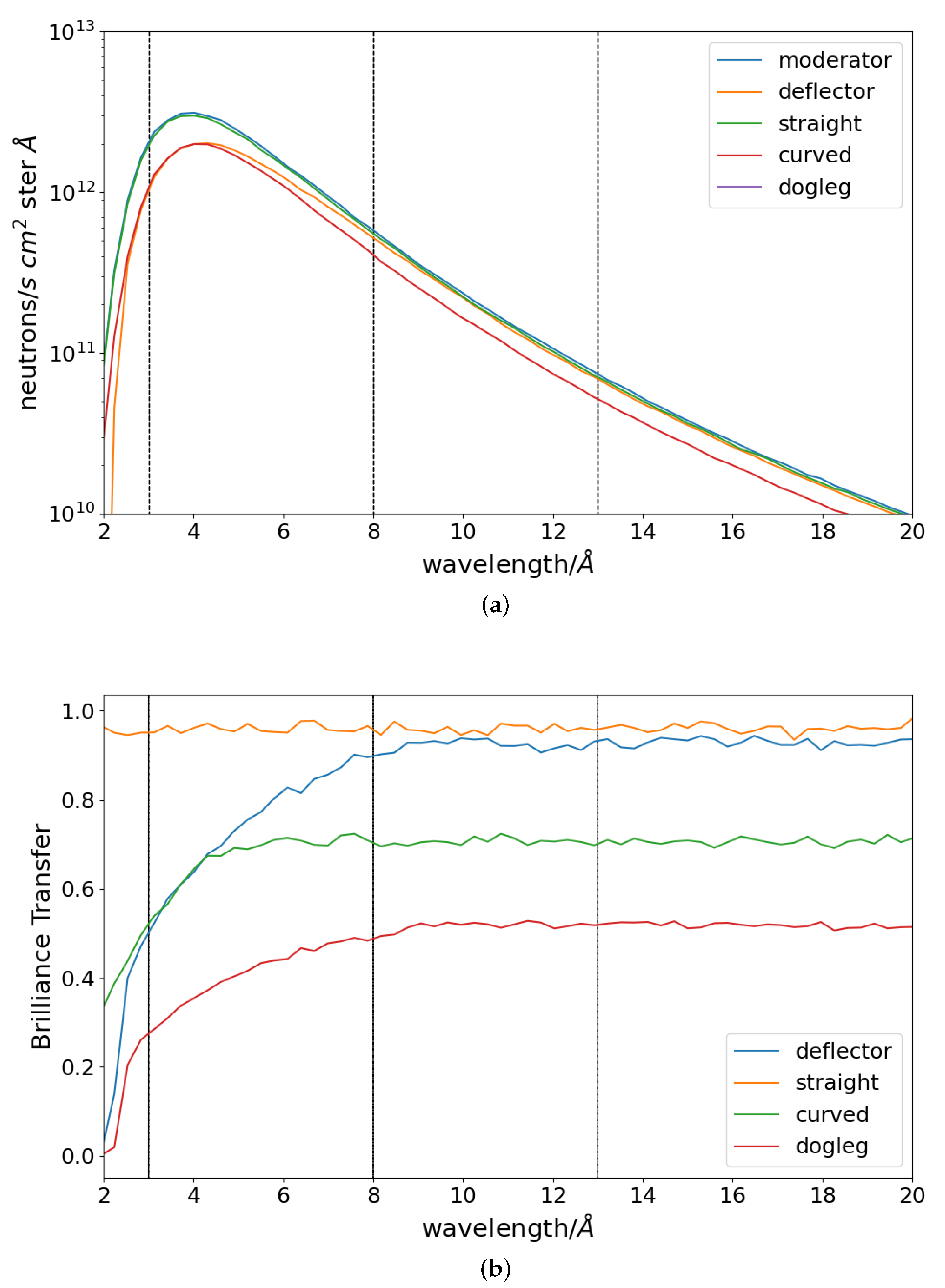
The deflector, dogleg, and bender were examined in order to evaluate the optimum transport mechanism from the monolith to the bunker wall. Restrictions on the materials were the exclusive use of metal substrates inside the bunker and a maximum m-value of m = 4 to prevent too strong degradation due to the high radiation field inside the bunker [
10]. The available length inside the bunker is 9 m, including 3.5 m of the monolith insert. The minimum distance to bridge in vertical direction was 20 cm, as this is the width of the anticipated hadronic shower coming from the target and the moderator that should not propagate along the neutron guide to the sample. By vertically shifting the neutron guide by the specified 20 cm or more, this background can be harmlessly absorbed in the bunker wall. This vertical displacement also has the advantage of keeping the instrument straight within its assigned angular wedge and avoid interference with neighbouring instruments.
The deflector neutron extraction is the finally chosen solution for the neutron extraction system. The most striking reason for that is given by the performance shown in
Figure 3. Looking at the spectra and the detailed data of the deflector explains this behavior. As detailed above, one of the primary objectives of the extraction is to block the direct line of sight. This is most easily achieved by inclining the neutron guide or, as in this case, the upper section of the neutron guide until the full cross section of the neutron guide is covered. For SKADI, this means that 3 cm needs to be covered. The restriction of m = 4 and the lowest wavelength of neutrons to be transported of
Å leads to the following considerations:
The critical scattering angle of m=4 is
= 0.087 Å
. Using this to find the angle of inclination for the upper surface of the neutron guide, we need to use
which yields
, using
Å. We chose the lower value for
for this calculation in order to increase the window of accepted neutrons. Finally, we chose
as the engineering requirement. This shifts the accepted wavelengths to higher values, which is not a drawback as the targeted wavelength band starts at
Å. Because the drop in intensity at the critical edge is centered around
= 0.087Å
and being in the area of the highest flux, there may still be significant contributions at higher Q-values. Additionally, this gives a slightly relaxed engineering margin, as now the complete cross section of the neutron guide can be covered by an inclined upper neutron mirror in the guide within 2 m using
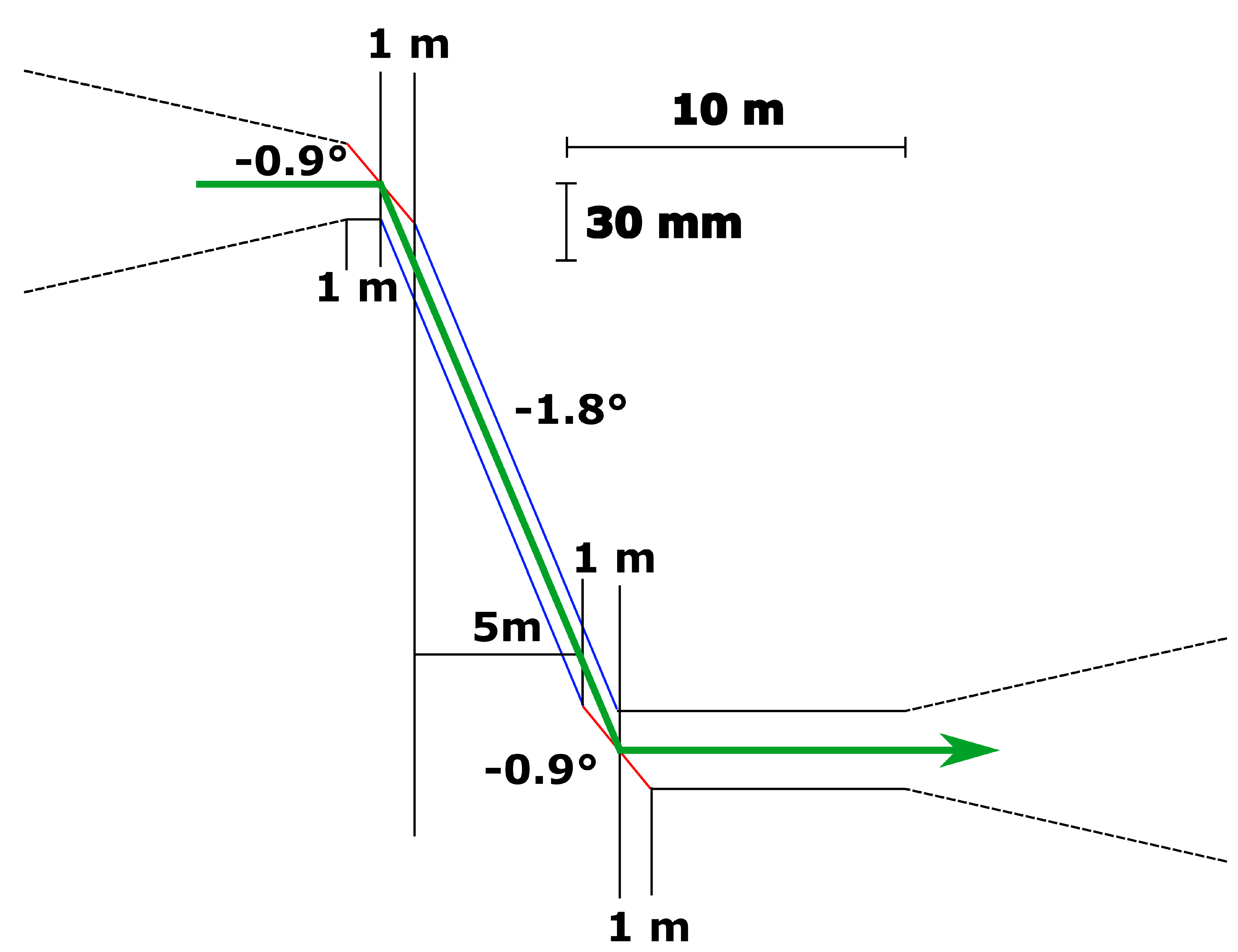
. Those relaxations of the exact requirement, the slightly sharper inclined mirror as well as the larger coverage of the neutron guide cross section benefit the function of rejecting low wavelengths efficiently and ensuring that the line of sight is covered. The same setup that is rotated by 180
is used at the exit end of the neutron extraction, since the neutrons have to be reflected into the horizontal plane again. This means the middle section is 5 m long and the inclination of that middle section should be twice the inclination of the entrance and exit mirrors in order to transport the neutrons with as few reflections as possible. Thus, the central section is a 5 m neutron guide, being inclined by 1.8
.
Figure 4 depicts a drawing of the cross section. The entry and exit part mainly function as an inclined mirror to deflect the desired neutrons by the necessary amount. This functions much like a periscope. The total deflection of the beam that is achieved by this setup is 22 cm, which fulfills the requirement of more than 20 cm. This double reflection should reduce the production of secondary particles in the second footprint of the beam in the supermirror to suppress background. Moreover, the primary hadronic particle shower of the target onto the bunker wall is calculated to be approximately
cm
, i.e., 10 cm in vertical direction from the center of the beam. Offsetting by 22 cm should also reliably suppress that source of background.
2.2. Chopper
Details regarding the chopper setup of SKADI have already been published, including the analytical calculations used to develop a balanced chopper setup [
11]. SKADI will provide the full infrastructure for four choppers, only equipping the first two positions (bandwidth and frame-overlap). High resolution choppers thus can be added at a later time. This results in chopper positions of 15.5 and 22.85 m (for 7 and 14 Hz) with additional chopper pits at 26.3 and 26.6 m. The choppers are optimized for a transmission of neutron wavelengths between 3 and 8 Å and offer the option for pulse skipping mode to achieve a wider wavelength band of 3 to 13 Å.
It should be noted that the simulation always assumes perfectly absorbing chopper disks. Our workshop can reliably produce chopper disks absorbing better than that are averaged over the full shaded area.
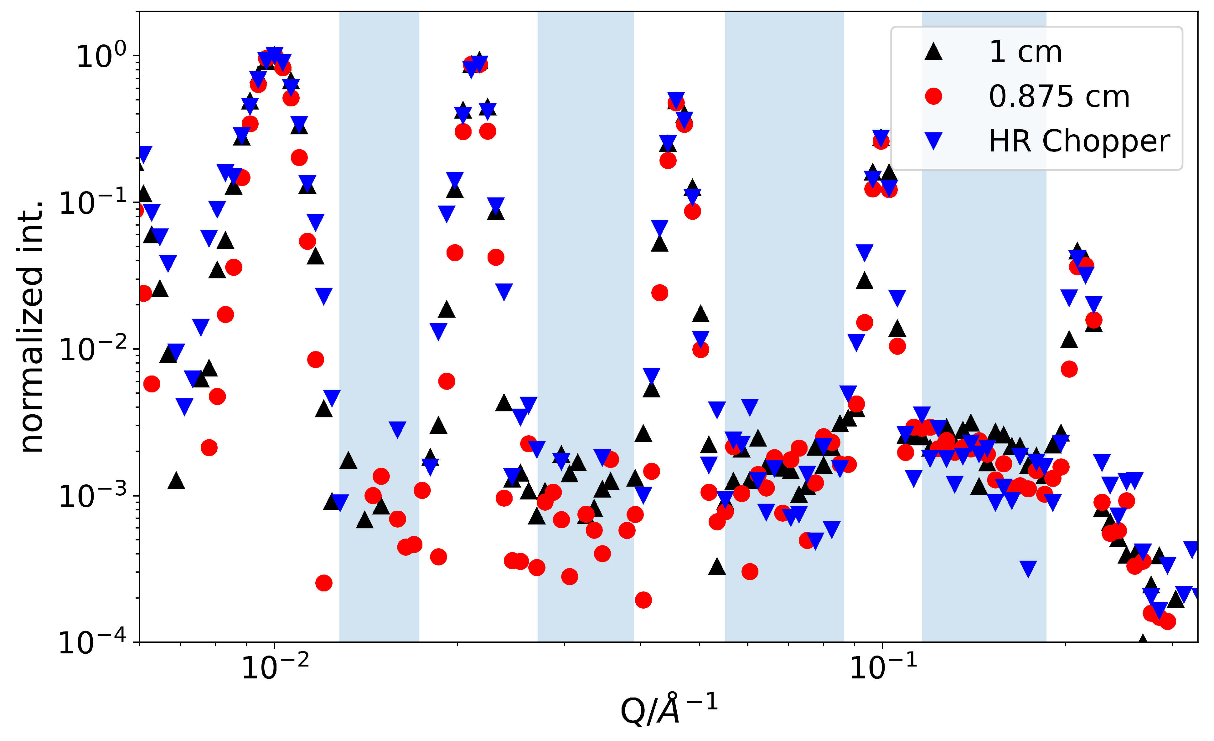
In order to elucidate the impact of high resolution choppers, the different achievable resolutions for simulated
-peaks are shown in
Figure 5. Here, we compare the resolution improvement by either the additional choppers or a reduction of the slit size while only using two choppers. While the wavelength resolution
can be considerably improved by using four instead of two choppers, this does not fully feed into a much improved Q-resolution
, as in the pertinent Q-range the aperture at sample position and the pixel size of the detector play a dominant role. However, looking at the simulated scattering from a sample creating exact
-peaks, it can be seen that the background is lowered by approximately 10% when comparing the smaller apertures with the 1 cm apertures combined with high resolution choppers. Meanwhile, the peak width is nearly unchanged. This means a better signal-to-noise ratio can be achieved. Here, it also should be noted that the absolute count rate of contributing neutrons (neutrons that are scattered within a peak) is bigger by a factor of 2 in the case of the four chopper solution.
Because the choppers also should inhibit frame overlap between the different pulses, it needs to be considered that this function is still adequately performed by a set of two choppers. Simulations showed that at 40 Å an additional signal is visible with a relative intensity of compared to the 3–8 Å wavelength band. For initial operation, this seems to be appropriate, at a later time a frame overlap mirror may improve this signal ratio, even without the use of additional choppers. Here, it also should be noted that, in addition the 40 Å neutrons will be attenuated far stronger by any window material. Additionally, in the case of a sufficiently long collimation, they will drop out of the collimation and be absorbed (∼0.4 mm drop per meter flight-path for a 40 Å neutron).
2.3. Collimation
The collimation allows for four distinct collimation lengths of 20, 14, 8, and 4 m. All of the collimation slits can be set between the full beam width of
and fully closed with independently moving blades from top, bottom, and both sides. Changing the collimation length means that at the chosen collimation length an aperture is inserted into the beam. All the neutron guides from the moderator to the aperture are left transporting the neutrons to the aperture. All of the neutron guides afterwards are removed from the beam. In the case of SKADI, the removed guides and slits are replaced by
passive blinds made from boron carbide [
12]. Those remove stray neutron propagating parallel to the main beam and reduce the background. The neutron guides will be placed on sledges to be moved in and out of the beam while maintaining the alignment.
Additionally to the classical pin-hole setup, a very small-angle neutron scattering (VSANS) setup with fixed slit-collimators will allow for accessing Q-values down to several times 10
Å
[
13].
2.4. VSANS
With a very small-angle scattering (VSANS) setup, SKADI will be able to reach Q-values down to several times
Å
. This VSANS section will be inserted behind the last collimation blind at 4 m collimation length. The collimator will be 2 m long and made out of six radial collimators of 33 cm length each. They will be precisely aligned on an optical bench. The slits will be 3 cm high, 100
m thick, and coated with Gadolinium. There will be 50 lateral slits to cover the 3 cm wide beam. The VSANS radial collimator is designed to produce a beam of approximately 3 mm, approximatively the size of the pixels of the central detector, at 20 m sample-detector distance [
14,
15].
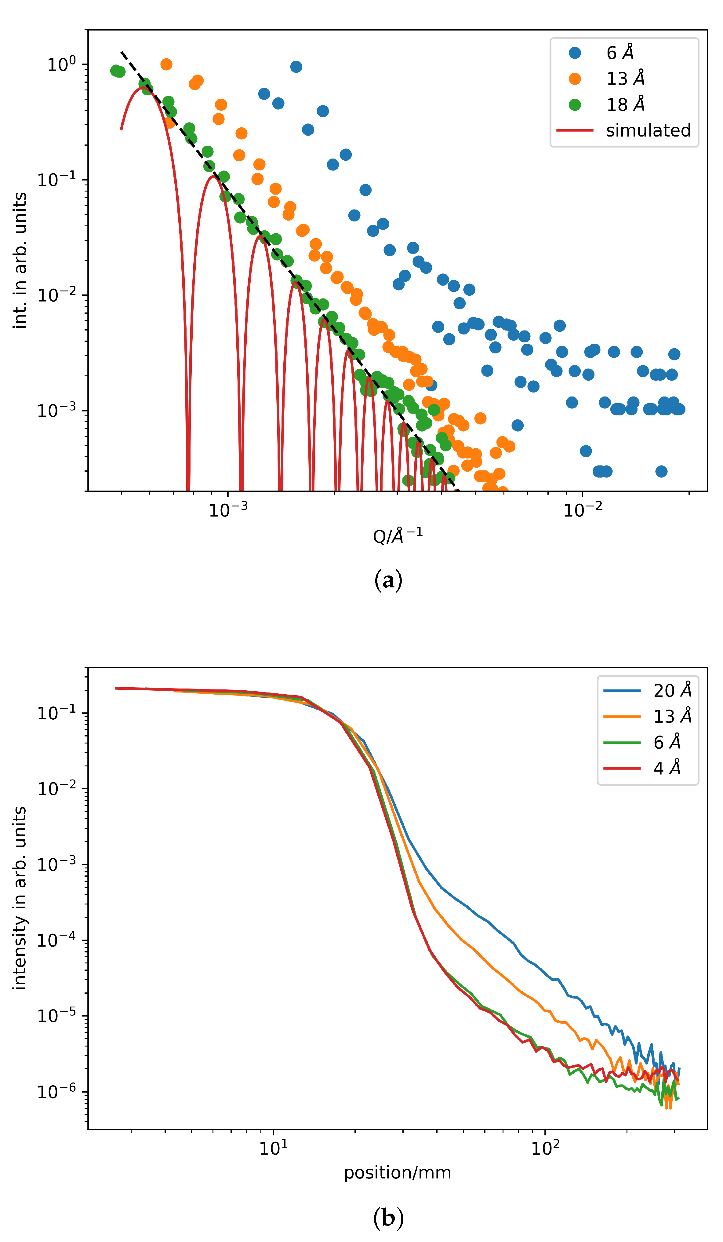
This means that, in the final setup, there will be a slit-convoluted signal, of 50 parallel slits, on the detector. Treatment of those slit geometries has long been a standard in the literature [
16,
17], so data treatment should be straight forward. Tests of this setup have already been performed at LLB, CEA Saclay, Gif-Sur-Yvette. In these tests, only a single collimator slit and a point-like beamspot (30 mm × 96 mm) was used.
Figure 6 shows the corresponding scattering data. From the data shown, it is also apparent that, at SKADI, a higher detector resolution and smaller usable slit size (at still acceptable flux) will directly lead to smaller achievable Q-values.
2.5. Polarizer and Guide Field
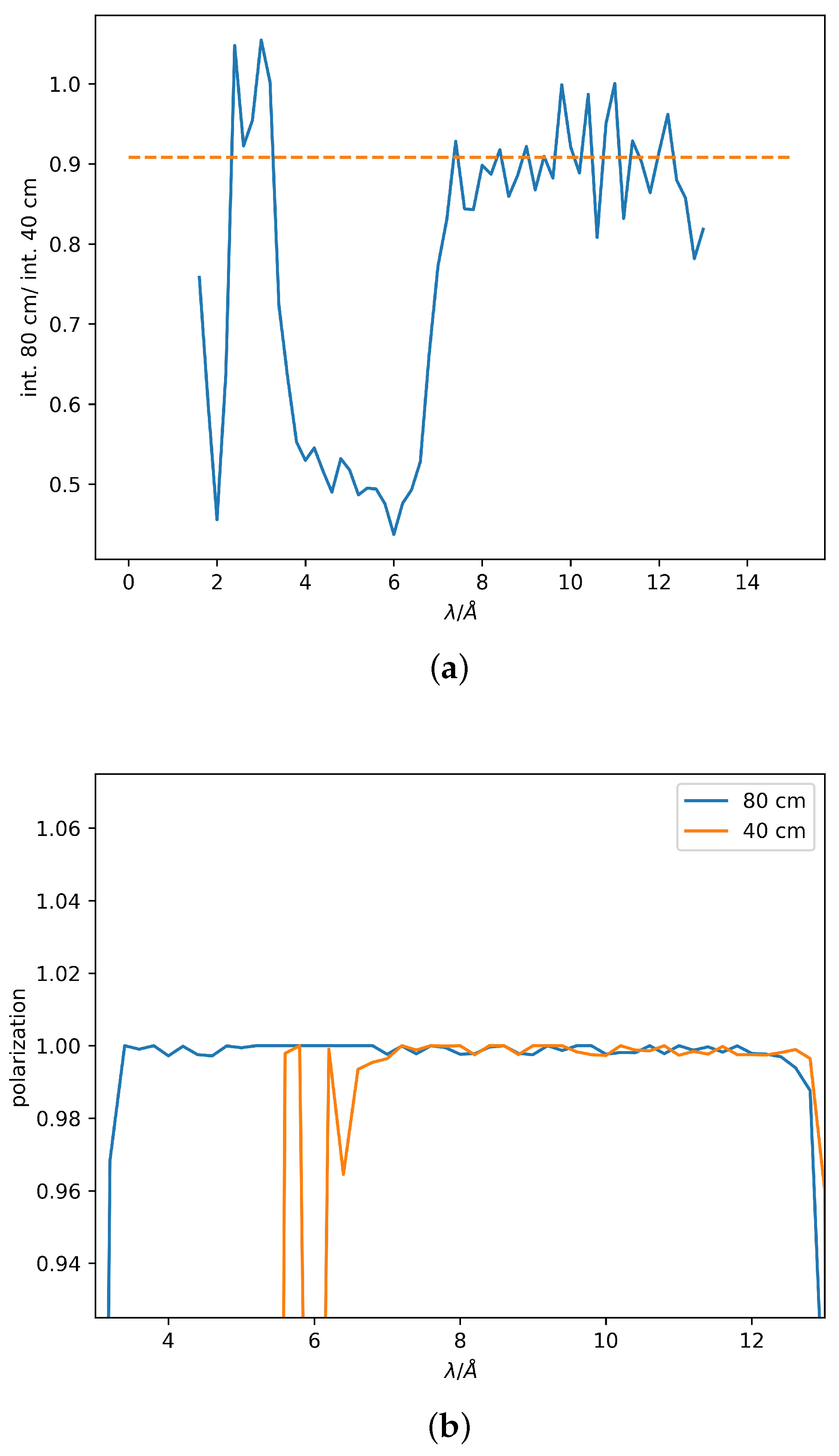
In order to provide polarized neutrons with an optimal degree of polarization over the complete wavelength band SKADI will feature two polarizers optimized for the low (
= 3–8 Å) and high (
8–13 Å) wavelength band. This is achieved by two cavities with a single slanted supermirror that provides the polarization.
Figure 7 presents the respective polarization and transmission. One cavity is a double coated Fe-Si supermirror with m = 2.5 in V-geometry using the corresponding McStas component [
9]. Here, one additional polarizer position is left unoccupied for future upgrades.
In order to maintain the polarization throughout the collimation, it is necessary to keep a homogeneous magnetic field after the polarizer until the sample position. While the field strength may vary, the direction needs to be consistent and should never flip. Calculations for permanent magnets that are aligned along the collimation show that a field strength between 5 and 13 mT can be maintained throughout the collimation, including all components, such as choppers. The chosen field direction is perpendicular to the beam direction. To also allow for different spin orientations, a spin flip is realized by a radio-frequency spin flipper directly after the polarizer [
12]. The foreseen probability for a successful spin flip is ≥99%.
2.6. Sample Area
The sample area, as such, is the main area where the experimenter will feel the strongest impact of the design in terms of usability. A kinematic mounting system will be installed in order to allow for an effective and speedy setup of the different experiments to be performed at SKADI. This kinematic mounting system will allow an off-instrument preparation of the experimental setup and several user groups have already developed corresponding sample environments [
4,
5,
6]. This setup is designed to take up a load of up to 990 kg on the area of a EUR-pallet. It is limited to ≤1000 kg to fulfill the requirements of the machine directive, upon verification higher loads are possible. Several heights of optional spacers are also prepared, as well as appropriate moving tables in order to accurately position the sample environment. The base plate for the system will be aluminum EUR-pallets with an adapted three-point mounting integrated into the pallets.
In addition to those verifications, the shielding of the sample cave has been designed to avoid magnetic disturbances of a He-analyzer for polarized neutrons. In order to achieve this, the magnetic permittivity of all walls is limited to 1.2, on average, and never exceeds = 1.8.
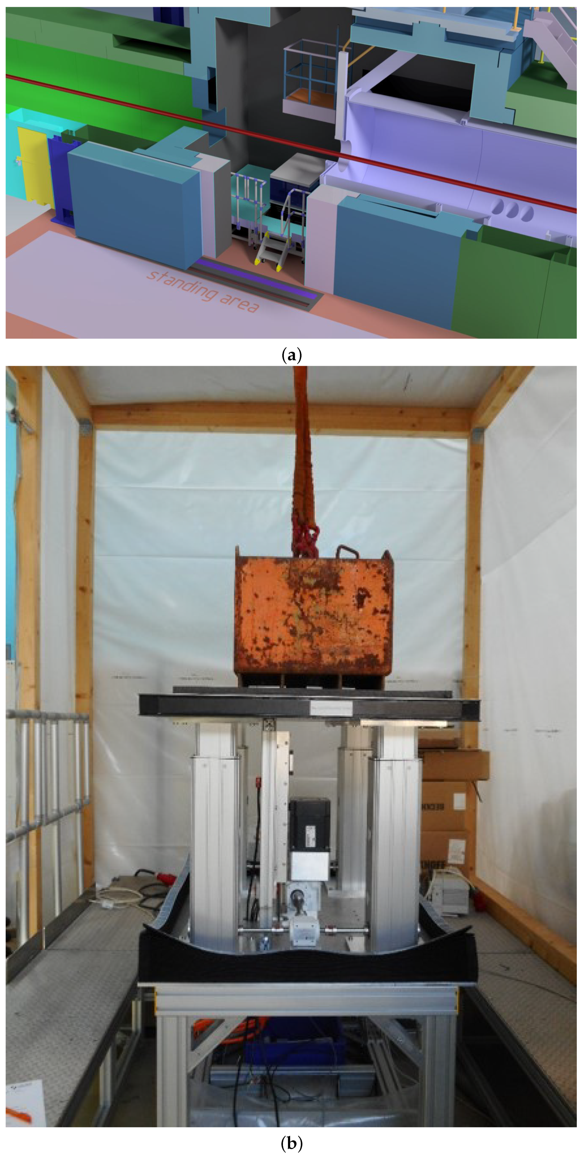
Additionally, the m large sample area will feature a false floor, below which cabling and hoses for experimental connections can be routed. The defining sample slit of the collimation will be mounted on an extendable nose in order to minimize the free flight path of the neutrons in air.
Figure 8 details the setup. Please note that the routing of hoses and cables from top as well as from the side is also foreseen, in order to route supply media and controls to the sample environment with a closed shielding. Access from the top is intended to facilitate working with cold fingers in cryostats or other, similar top-heavy, sample equipment. For a safe handling of those sample environments also, a crane is foreseen.
The top of the generic sample environment is a breadboard of the same size as the EUR-pallet. There, all equipment can be mounted on the threaded grid.
The achievable flux at sample position is 7.7 × neutrons scm with 4 m collimation length. This is based on the McStas simulation of the instrument, as described in this manuscript.
2.7. Detector
The detector used for SKADI will be a SoNDe-type pixelated scintillation detector [
7,
18,
19,
20]. Apart from the high-flux capability necessary [
21], especially in the area of the primary beam, this detector also provides an excellent scalability and geometric freedom arranges the available active surface area as needed. In our previous publications, we also tested the sensitivity of our detector system, which is on the order of 90% for neutrons with a wavelength of
Å.
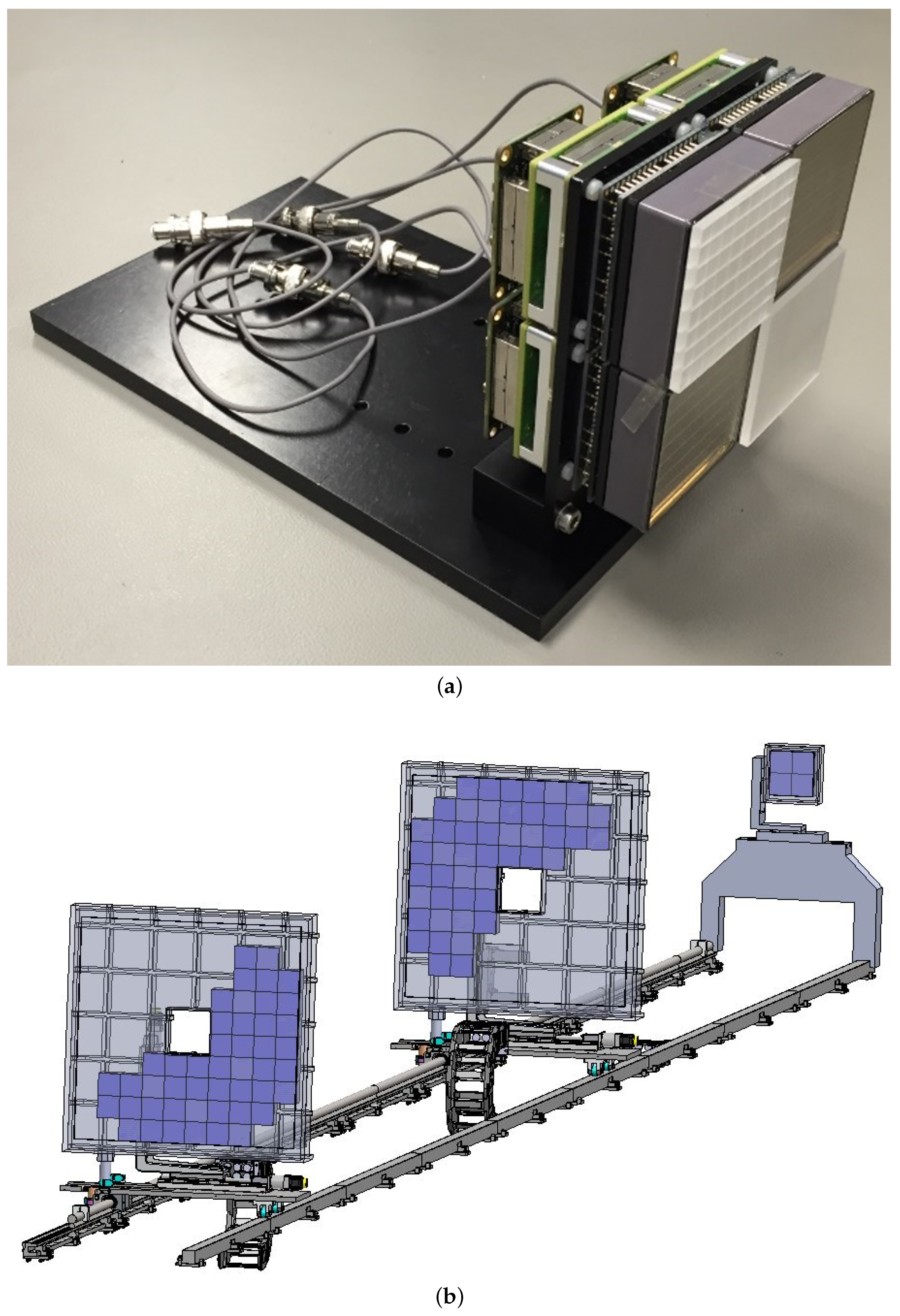
In order to achieve a high simultaneous Q-range, SKADI will be equipped with three SoNDe type detectors, two of which are mounted on a movable carriage and have an aperture for low-angle scattering.
Figure 9 shows the proposed arrangement of detector area. Here, it should be noted that the center hole is always
cm
and the distance ratio between the forward and middle detector, as measured from the sample, is always 1/5. The central detector is always at the same distance as the collimation setting to ensure an ideal mapping of the sample aperture on the detector, while the rear detector is fixed in the back, outside of the detector tank at 20 m. While, for some settings, there may be geometrical gaps, there is never a gap in Q-space due to the wavelength band used for the scattering experiment. In addition, the rear detector also serves as a beam monitor. A semitransparent beamstop will allow for investigating the full scattering down to the lowest angle, as the primary beam is only attenuated and never blocked.
The pixel size throughout the detector is
mm
everywhere, apart for the 20 m position, where the resolution is
mm
, in order to allow for an optimal resolution. There are several considerations going affecting the choice of pixel size. In fundamental terms, the smaller pixels allow for a higher count rate, since the used detector technology has a roughly constant dead time per pixel. Thus, decreasing pixel size and increasing pixel number linearly increases the achievable count rate. Furthermore, on most current day instruments, slit sizes of roughly 1 cm in both directions are chosen as a sample blind, while the final collimation blind before that is on the order of a few centimeters in both directions. Using those numbers, the SKADI detector would not increase the achievable resolution, since the beam size gives the limit. However, for SKADI with the higher flux, smaller apertures will probably be more commonly used. Additionally, when considering the VSANS data that were recorded with the VSANS prototype that will be used by SKADI (
Figure 6), it is already now apparent that the detector needs a higher resolution, in order to take full advantage of the better flux and optics.
The front and middle detector will be in a box at atmospheric pressure and located inside the vacuum tank, which is 20 m long and 2.2 m in diameter and made from aluminum [
22]. Vacuum hoses in two cable chains will be required to bring the air from outside the vacuum tank to those air boxes. The cooling of the electronics and the signal out will also be routed through those hoses. Because of the 1/5 ratio of their relative distances from the sample, both of the detectors will have their own motorized support and share a common guiding rail.
3. Summary and Scientific Performance
The overall goal of SKADI is to cater to a wide range of scientific needs in order to allow for most conceivable small-angle neutron scattering experiments. This is achieved by a versatile sample area, a well adaptable collimation, as well as a high-flux capable detector for single shot experiments of kinetic transitions in samples. This combination should allow excellent experiments, resulting in high-profile scientific investigations and publications.
Those capabilities are accompanied by a world leading high flux at sample position and an excellent resolution down to very low Q-values around several times 10Å in a pin-hole setting and even lower using the VSANS setup. The upper Q limit is well above 1 Å, depending on the specific setting. In between those limits, dynamic Q-range of are feasible, which makes single shot experiments over a wide range of length scales in the sample feasible.
This could be achieved by thoroughly designing SKADI from the neutron extraction to the detector with scientific performance and applicability in mind. This means that each component was first simulated as a standalone setup with a generic neutron flux, until the desired performance criteria where met. Afterwards, the specific component was simulated in tandem with the rest of the instrument and the model of the ESS moderator to assess a realistic scenario. While doing this, the pertinent parameters, such as the m-values of the guides, as well as the length and position of components, were varied in order to make sure the configuration was in a stable performance maximum. The SoNDe detector was finally developed specifically for use in a SANS instrument [
7,
18,
19,
20].
Summarizing this procedure, for SKADI there are a few key properties of such a SANS instrument at a high brilliance spallation source, such as the ESS.
Starting at the neutron extraction, with the necessity to displace the primary beam in order to avoid a direct view of the moderator from the sample position, the general approach of using a long curved guide would have resulted in either a very long bunker or an extremely poor transmission. This can be mitigated using a channeled bender, but the technical limitations on lifetime in a hard radiation environment and reflectivity strongly limit that approach. Additionally, mostly short wavelength and high divergencies profit from such a setup, which are not the most profitable neutrons to transport for a SANS experiment. Using the deflector setup, a twice reflected direct image of the moderator can be transported. By choosing the angles and coating appropriately, even a low wavelength cutoff can be obtained, which is both beneficial for the experiment itself, as well as shielding of the rest of the instrument.
Continuing to the chopper setup, it is clear that a time of flight instrument needs at least two choppers to define the wavelength band and prevent the frame overlap from secondary neutrons. The acceptable wavelength band is defined by the farthest detector position, and an optimal position for the first chopper is as far upstream as technically feasible, since this removes background farther from the detector. In combination, those two requirements then also define the position of the second chopper. The high resolution choppers, which still can be installed on SKADI as an upgrade, have advantages, as shown in this manuscript, however are not strictly necessary for a high performance SANS instrument and would be most profitable in the case of weak signals, a problematic signal to noise ratio, or a combination thereof.
Regarding the polarization setup, SKADI features the optimal solution both for long and short wavelengths, as well as the possibility to later upgrade for either even longer wavelength or any other optical component that might be considered to be useful. Together with the spin flipper and the He-analyzer that can be installed at the sample position, this gives SKADI the capability to both investigate magnetic samples, or, more generally, spin dependent scattering, for all orientations, as well as the possibility to use polarization for the suppression of spin-incoherent background, which might prove useful for weakly scattering samples, where simply prolonging the measurement does not necessarily improve the data anymore.
In terms of sample environment, there is already now a lively community working of developing their own custom sample environments for SKADI. This takes advantage of the open sample environment system, which allows simple access to the sample cave with predefined kinetic mounts and other interfaces. This will both facilitate the design of custom sample environments by other users, as well as shorten the setup times between beamtimes, even for complex sample environments, since they can be prepared to a very high degree off the instrument, before the actual experiment starts.
Finally, the SoNDe detector is a completely new development, which is aimed to allow the use of the high brilliance of the ESS to capacity. The semitransparent beamstop will allow SKADI to measure down to virtually Q = 0 Å, only being limited by the pixel size. In addition, no attenuation of the beam is necessary, since the SoNDe detector will be linear, even for the highest intensities available. Furthermore, the free positioning of the detectors will allow an optimal selection of resolution, collimation, and flux for any experimental setup.
Taken together, all of these features present SKADI as one of the world leading SANS instruments and an excellent addition to the ESS instrument suite.


 ,
, 


