Article

Quasi-Passive Resistive Exosuit for Space Activities: Proof of Concept

1
XoLab, Department of Advanced Robotics, Istituto Italiano di Tecnologia (ADVR-IIT), 16163 Genoa, Italy
2
Department of Center for Micro-BioRobotics, Istituto Italiano di Tecnologia (CMBR-IIT), 56025 Pontedera (PI), Italy
3
Centro de Automática y Robótica, Consejo Superior de Investigaciones Científicas-Universidad Politécnica de Madrid (CSIC-UPM), 28040 Madrid, Spain
4
European Space Research and Technology Centre (ESTEC), European Space Agency (ESA), 2201 Noordwijk, The Netherlands
*
Author to whom correspondence should be addressed.
Appl. Sci. 2021, 11(8), 3576; https://doi.org/10.3390/app11083576
Submission received: 26 February 2021 / Revised: 29 March 2021 / Accepted: 8 April 2021 / Published: 16 April 2021
(This article belongs to the Special Issue Advances in Aerial, Space, and Underwater Robotics)

Abstract

:
The limits of space travel are continuously evolving, and this creates increasingly extreme challenges for the crew’s health that must be addressed by the scientific community. Long-term exposure to micro-gravity, during orbital flights, contributes to muscle strength degradation and increases bone density loss. In recent years, several exercise devices have been developed to counteract the negative health effects of zero-gravity on astronauts. However, the relatively large size of these devices, the need for a dedicated space and the exercise time-frame for each astronaut, does not make these devices the best choice for future long range exploration missions. This paper presents a quasi-passive exosuit to provide muscle training using a small, portable, proprioceptive device. The exosuit promotes continuous exercise, by resisting the user’s motion, during routine all-day activity. This study assesses the effectiveness of the resistive exosuit by evaluating its effects on muscular endurance during a terrestrial walking task. The experimental assessment on biceps femoris and vastus lateralis, shows a mean increase in muscular activation of about 97.8 % during five repetitions of 3 min walking task at 3 km/h. The power frequency analysis shows an increase in muscular fatigue with a reduction of EMG median frequency of about 15.4 % for the studied muscles.

1. Introduction

Bone density loss and muscular atrophy are an inevitable outcome of exposure to micro-gravity [1,2,3,4]. The average rate of bone loss is about 2.5 % per month in at least one skeletal site [5]. This is very significantly higher than the bone density loss due to osteoporosis. In addition to bone density loss, muscle atrophy is also of great concern during spaceflights. Fitts et al. [6] have observed muscle strength reductions of up to 30 % during extended space activities, with an exponential decay related to the duration of the flight [7]. Many countermeasures have been evaluated during flights, and in recent years, promising results have been shown [8]. Pharmaceutical countermeasures, either alone or in combination with exercise, show potential benefits [9]. Physical exercise has also been tested in many forms over the past four decades of spaceflight. Typical exercise equipment available on long duration space missions (Mir and Skylab) is mainly designed to promote aerobic and muscular endurance and is based on Combined Operational Load Bearing External Resistance Treadmills (COLBERT), Stationary Bikes, and elastic expanders such as the Exer-Genie [10]. With the start of operations on the International Space Station (ISS), the interim Resistive Exercise Device (iRED) [11], and later in 2008, the Advanced Resistive Exercise Device (ARED) [12] have been used as countermeasures to promote resistance exercise and are used together with applied loads to simulate earth’s gravity. A recent study that examined the effects of space flight coupled with exercise, showed promising results on mitigation of micro-gravity side-effects without the use of pharmaceutical agents [8].
Although the use of exercise devices does provide promising results. The average time spent doing the aerobic exercise while in space, with cycle egometer (CEVIS) and treadmill (TVIS) is 120 min/wk and 160 min/wk respectively [13]. The cycle exercise generally ranged between 100 and 150W (light to moderate effort activity), and the walking/running activities on the treadmill were performed at an average speed of 3.0 to 9.0 km/h. Cycling and walking/running activities generate a metabolic expenditure ranging from 2 METS (3 km/h walking speed) to 8 METS (9 km/h walking speed) with 5.5 METS and 7 METS for the 100 and 150 watts cycling activities respectively [14]. In spite of the positive potential of these systems, undesirable side-effects are that the form-factors of these training systems restrict the crew to a specific location within the station and require a large vibration isolation system to minimize disturbances imparted into the spacecraft during workouts [15]. Therefore, these concentrated exercises regimes require the crew to train in isolation or semi-isolation for about an hour and half every two days in a dedicated training room. Moreover, the lack of monitoring systems does not allow for real-time activity feedback on specific physical parameters or muscle strength assessments, although this would be very beneficial.
Wearable robotic device used as countermeasures for micro-gravity activities could represent a solution to address several of these drawbacks in one single device as presented in [15]. In the past decade, the use of exoskeletons has grown in several fields. The most common such domain is rehabilitation, spanning from stationary exoskeletons, such as the Lokomat [16] and LOPES [17], to mobile exoskeletons to provide assistance to paraplegics when walking [18,19]. Recently, exosuits (soft exoskeletons), which form a new generation of exoskeletons have been presented, [20,21,22], with ankles, knees or hips that are supported by a soft or hybrid structure driven by active tendon connected actuation systems. These exoskeletons use a soft wearable structure, which helps to reduce the burden created by the assistive device. They address not only the degree of assistance but also the usability/acceptance by end users. Within this paper, we explore the development of the XoSoft exosuit, which represents a soft, modular, bio-mimetic and quasi-passive exoskeleton to assist users with low to moderate mobility impairments such as the elderly, post-stroke and partial spinal cord injury subjects, [23]. Quasi-passive actuators (QPA) that rely on clutches, are used to modulate the forces generated by the passive elements employed to store the mechanical energy. The authors have demonstrated in the latest version of their soft wearable device; “XoSoft Gamma prototype” [24], the effectiveness of the technology, where soft pneumatic QPAs [25] have been employed to modulate the level of assistance throughout the gait cycle. This assistive device features a modular and reconfigurable design of hips, knees and ankles actuators. The effectiveness of the assistance provided by this exosuit in terms of improvements to rehabilitation parameters has previously been proven [23,26,27], as has the comfort and acceptability [28,29].
The use of dedicated, comfortable exoskeletons that provide continuous physical training while performing normal activities, without the need to dedicate time and space to physical training, would be extremely beneficial for the crew and their wellness. The introduction of such wearable devices will change the current physical training paradigm for all astronauts. The concept developed in this paper is a functional exosuit with a comprehensive suite of sensors, actuators and soft structures that takes into account both the exercise requirements and long terms user comfort. This will permit continuous all-day training of all body segments (e.g., forearm, shoulders, abdominals, upper and lower legs). The astronauts will train their limbs, as they would under normal gravity on earth, without the need to dedicate long portions of their day to maintaining health/fitness. Previous studies have shown that a low-intensity resistance training with relatively tonic movement and a short rest period causes increases in muscular size and strength [30], and slow-speed resistance training has also shown to effectively cause an increase in muscular strength [31]. In conclusion, prolonged continuous low- to moderate-intensity endurance type exercise training is equally effective as continuous moderate- to high-intensity training in increasing whole body and skeletal muscle oxidative capacity (main responsible for the muscle regeneration process) [32].
The exosuit will be used during normal activity and it will be able to identify and understand the user’s motion, generating resistance to the user’s limbs and simulating the effects of gravity. To achieve these goals, the exosuit will employ novel, dedicated actuators, sensor strategies and intelligence. The exosuit will also be equipped with wearable sensors to monitor, locally and remotely, bio-signals needed to guide the user during daily activities. Moreover, the transmission of this data to the ground support team will permit remote monitoring and continuous checking of the crew’s health.
This work describes the conversion of the XoSoft Gamma exosuit, previously developed for terrestrial rehabilitation, to a resistive exosuit to provide countermeasures for micro-gravity activities during medium/long space flights. These modifications and enhancements introduce a number of application specific improvements: (i) bilateral knee flexion and extension actuation units, (ii) a dedicated control strategy designed to generate resistance while carrying out normal walking activity, (iii) assessment of the performance of this control strategy, and (iv) a dedicated soft sensor strategy which is fully integrated and validated. The system design and control strategy are illustrated in Section 2. Experiments to assess the effect on muscle activation, of the sensing subsystems, and the overall resistive device are conducted and presented in Section 3.

2. Materials and Methods

Currently astronauts spend an average of six months living, and working within their spacecraft. Their activities consist of conducting sophisticated experiments using high precision tools and equipment [33]. Beside their main work activities, physical training and exercise forms a major, and vitally important portion of their waking hours. This training activity is essential to counter the effects of long term exposure to zero or near zero gravity. Muscle atrophy is of great concern during spaceflights, with muscle decline of up to 30 % having been measured during extended flight durations. This muscle atrophy leads directly to reduced peak force generation in all the limbs [6]. In order to maintain their muscular tone, or at least reduce the muscular degradation rate, daily physical training sessions lasting from two to four hours are required. The platforms needed for this exercise are heavy and confined to specific areas onboard the spacecraft where they are mounted on sophisticated supports to reduce the vibrations generated by the training activity. Excessive vibrations might interfere with the spacecraft instrumentation and associated measurements. Mitigation of micro-gravity side-effects, particularly muscle atrophy, could benefit from the use of functional exosuits.

2.1. Wearable Device Requirements and Technology Overview

Any wearable device to enable continuous training has to be a light, comfortably and suitable for whole day use. Exosuits are well suited to this role since they offer comfort and usability, in a soft garment with a not rigid mechanical design that allows easy integration within the clothing typically worn by astronauts. The exosuit can also be intelligent; recognizing limb motions and consequently controlling, where and how, the modulated forces have to be delivered to generate the resistance needed by the target body segments. The resistance must be provided by actuators with high autonomy and very low power consumption, thus the selection and design of the particular mechanisms or actuation methods is critical. As the system will be used in a micro-gravity environment, sensors and control must be developed considering that normal earth-based signals such as the gravity vector and the earth’s polarity are not available.

2.1.1. Exoskeleton Structure and Actuation Strategy

For exosuits, traditional hard, rigid actuators are not suitable and new softer, more flexible actuation solutions are required. The development of exoskeletons using soft materials is an innovative field with many potential applications [34,35,36]. In 2007, Caldwell et al., proposed an innovative approach based on the use of soft, inherently compliant, pneumatic muscle-like actuators [37]. Later other researchers employed cable driven actuation [38,39]. In recent work, soft clutches have been identified as a promising option for human-robot interaction and soft robotics. Current research on soft actuators aims to develop clutches, brakes, dampers and devices based on technology such as: specific phase change materials [40,41,42]; friction-based mechanisms [43,44]; granular jamming [45]; cable tensioning [46,47]; and pneumatic actuators [48]. Vacuum-controlled jamming (either particles or layers) is a highly promising and suitable technology that has found a number of uses within the robotics community [45,49,50,51,52,53,54].

2.1.2. Sensing Strategy

As with actuators, the sensing technology developed for exosuits needs to be soft and compliant, while still retaining the accuracy, reliability and robustness of conventional approaches. Many different types of sensors and technologies have been used in wearable systems and robotic exoskeletons [22,23,55]. Typically, mechanical sensors are used to monitor the position, velocity, and the torque of the human joints (i.e., elbow, knee, ankle, etc.) in addition to ground reaction forces, but in soft exoskeletons the sensing elements cannot be made of rigid materials. Thus, alternative sensing mechanisms should be considered. In particular, for the detection of joint movements, a possible solution is the measurement of the strain in the garment worn by the user. The strain variations can be correlated with the joint angles by means of specific algorithms. Soft strain sensors can respond to the externally applied stimulus (e.g., from joint movement) by exploiting different mechanisms, depending on the materials, micro/nanostructures, and fabrication process [56]. Traditional strain sensors are based on electrical resistance variation, arising from geometrical effects and the piezoresistivity of the materials themselves. Many of the approaches used in these strain sensors come from the area of skin-like artificial tactile sensing where, in addition to pressure, various mechanical parameters are retrieved e.g., tangential forces, texture, and vibrations [57,58,59], to mimic human tactile capabilities. These approaches are very influenced by the development of novel materials [58], device layouts [60], the study of different physical principles [61,62], and their application in various promising scenarios including the field of soft robotics [63]. From a transduction point of view, in addition to (piezo)resistive-based sensors [64,65,66], capacitive [67,68,69], optical [70,71], and inductive/magnetic [72,73,74,75] sensors have been demonstrated for wearable applications.

2.1.3. Control Architecture

One important and very specific feature of wearable robotics is the intrinsic interaction between the human and the robot; Human-Robot Interaction (HRI). This interaction is twofold: firstly, cognitive, because the human controls the robot that is providing the feedback to the human; secondly, a physical or biomechanical interaction leading to the application of controlled forces bidirectionally between the robot and the human [76]. The fact that a human is an integral part of the design is one of the most exciting aspects in the design of biomimetic and biomechatronic wearable robots. It does, however, also impose several restrictions, challenges and demands on the design of this type of device since it involves the cooperation of two dynamic control systems, i.e., human motor control and robot control, in a closed loop system. Both systems must be able to adapt to each other in order to stably achieve their common goal. The human-activity recognition is required to understand what kind of action the user is performing. Recently, researchers have proposed different automatic alternatives for activity recognition based on Artificial Neural Networks [77], rule-based and Quadratic Discriminant Analysis algorithms [78], Gaussian Mixture Models [79], gait segmentation based on triggering of mechanical sensors [24], online classification based on Support Vector Machine relying on kinematic variables [80], EMG-based control methods [81,82,83] and model-based control algorithms [84,85,86]. Each of these solutions are generically suitable but their use is strongly dependent on the specific application.

2.2. Proof of Concept

The XoSoft Gamma prototype, Figure 1, was developed within the XoSoft European project [87], and has been extensively demonstrated in [24]. The exosuit, which generates assistive forces that are applied to the lower limbs, was developed as an open platform for rehabilitation. It was designed using a User-Centred Design approach that emphasizes testing and experience gained at each stage of the development/prototyping. The flexibility of the systems (hardware and software), components and the design of the XoSoft Gamma exosuit itself, gave it a very high degree of reconfigurability, and although initially designed for rehabilitation it was easily modified to form a daily assistive device (or in the specific case, as a resistive device), featuring high modularity and reconfigurability aspects also in the control. The modularity, reconfigurability and capacity for repurposing inherent in the design of the XoSoft exosuit means that it can support/resist actuation of different joints (i.e., hips, knees and ankles), unilaterally or bilaterally, depending on the users’ needs. Moreover, the control strategy can be programmed to meet the demanded level of assistance (or resistance) requested by the user. Finally, the XoSoft exosuit garment is one-size-fits-all based on loose trousers (to allow a quick donning and doffing) with webbing elements for the fixation to the body, and actuator attachments along the lower limbs. These actuator attachments are used to install, on demand, the actuators on the body segments. One of the main defining characteristics of the XoSoft exosuit is the use of a quasi-passive actuation (QPA) principle. This means that the exosuit does not assist the user through an actuator of any kind (electric motor, pneumatic/hydraulic system, etc.), but rather uses passive elements that can store and release user generated mechanical energy. This energy storage and controlled release is regulated by an active component. The QPA has several advantages e.g., no need for a high-power actuation system, energy efficiency (giving high movement autonomy), and finally suitability for use in soft exoskeletons. The low-level controller developed for the pneumatic valves used to regulate the actuators reduces the air consumption, increasing significantly the autonomy of the system [24].

2.2.1. Exosuit Platform and Actuation Unit

The XoSoft exosuit has been iteratively developed to meet the safety critical requirements, and it is certified as class 1 medical device in conformity with the standard UNI ISO 60601. The exosuit can control up to six pneumatic actuators and weighs only 4 kg with a compact (200 × 400 × 150 mm) external backpack. The backpack includes a battery (4 Ah and 24 V) that allows the system to run for 6 h continuously (continuous operation of four active actuators, at a walking speed of 3 km/h). The system can, if required, be equipped with a pressure tank to support completely untethered operation. This adds only an additional 1.5 kg. Figure 1 shows the XoSoft Gamma exosuit, the actuator arrangement, sensing integration, and the garment physical structure. In particular, Figure 1 shows the arrangement of the four knee actuators, two coupled to the knee extension and two to the knee flexion. This actuation configuration is employed specifically for the assessment of the proof of concept presented in this work. The main technological elements composing this exosuit platform are presented in Figure 2, and some of the main characteristics are summarized as follows:
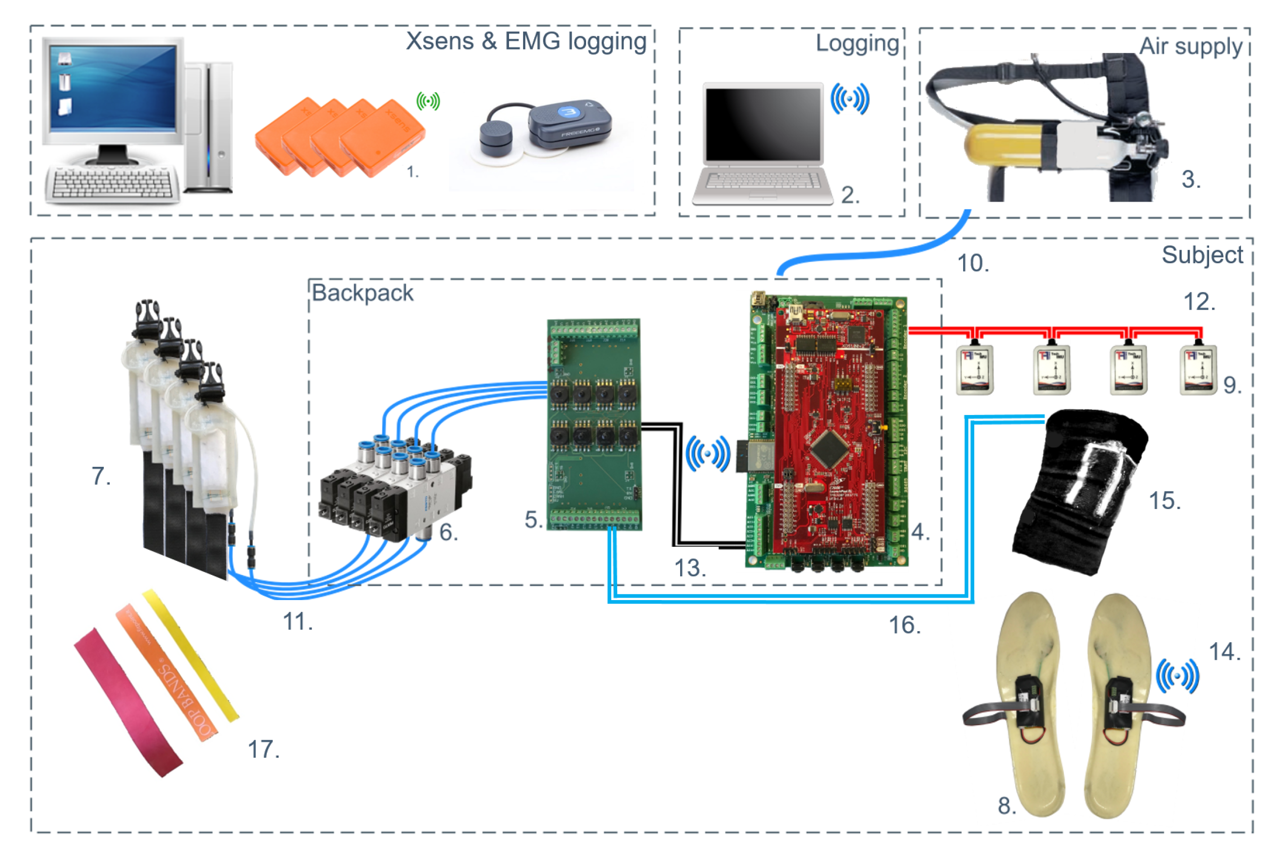
  • Quasi-Passive Actuation (QPA): is composed of a soft clutch (or textile based clutch [88] and Elastic bands (EB). The soft clutch (SC) creates controlled storage and release of energy. The EB stores the user generated mechanical energy.
  • Body Attachment: Body attachment is required to transmit the forces from the actuators to the wearer’s body. The body attachments consist of shoulder straps, fixation straps, belt, and actuation attachments.
  • Wearable Sensors: Sensors are used as an input for the motion segmentation. Insole sensors and two versions of knee angle displacement measuring sensors (details are reported in Section 2.2.3) are employed.
The QPA is composed of an EB and the SC connected in series. The actuation principle is based on modulation of a passive element (i.e., EB), which stores mechanical energy, and an active element (i.e., SC), regulating the storage and release of this mechanical energy between gait phases. QPA refers to any controllable element that cannot apply a non-conservative, motive force [89]. The SC is based on a combination of granular and textile jamming, with the electromagnetic clutch functionality mounted in series with the elastic element [88]. From the functional point of view, this is equivalent to an electromagnetic clutch mechanism, but it is soft, and directly mounted on the human joint without the need for any dedicated transmission (e.g., bowden cables). From the wearability viewpoint, the flexible nature of the pneumatic systems gives important advantages. The SC is a variable stiffness actuator, which controlling vacuum it ensures a controllable increase in the internal friction forces thanks to plastic grooves (while retaining the same volume), to modify the linear stiffness of the element. When the vacuum is applied, the SC is engaged, with the SC stiffness characteristic changing from elastic to rigid along the direction of pull (the relative motion of the two sliding parallel structures is blocked). Once the SC is engaged, any subsequent movement by the user causes elongation of the EB by the normal motion of the limbs. This motion is the primary mechanism for the effective transfer of mechanical energy between the user‘s limbs and the exoskeleton system. The EB elongates, storing mechanical energy, during part of the gait cycle, and then, at the end of the elongation, it releases mechanical energy back to the user in a controlled manner during its contraction. The EBs selected for the current proof of concept have the following characteristics: EB material: latex; Nominal stiffness: 0.5 N / % ; EB L 0 : 25 mm. The EBs stiffness characteristic is governed by a third order function of elongation percentage as in:
f k ( α k ) = a 3 Δ L k 3 + a 2 Δ L k 2 + a 1 Δ L k
with a 3 = 3.66 10 6 , a 2 = 0.002 and a 1 = 0.565 . Details of the EB design, setup, calibration and usage on the Xosoft prototype, are reported in [24]. The forces generated by the EBs are a direct function of its elongation. The torque generated on the assisted joint is proportional to the EB’s force, f k as shown in Equation (2).
τ k = R k ( α k ) f k = R k ( α k ) K E B ( Δ L k E B )
The torque provided by the actuation system is strongly influenced by the moment arm R k ( α k ) subtended by the cord L k , and by the cord elongation Δ L k . The cord elongation is completely supported by the EB, whereas the R k ( α k ) , function of the joint angle is expressed as in Equation (3).
R k ( α k ) = r k if   α k   is   < 0 L k L k L k ( α k ) s i n ( β k ) if   α k   is   0
For further details see [24].

2.2.2. Control Strategy

To control the QPA and the XoSoft exosuit, the main information required is the gait phase, since the clutches have two states (engaged and disengaged) that typically occur once per cycle. Consequently, the core of the control system can be a state machine that keeps track of the gait of the user. The gait cycle (time between two consecutive hell-ground contacts, heel strikes, of the same lower limb) consists in two main phases: (i) stance phase, that is the time between the heel strike of the foot and the toe off (from 0% to about 60%); and (ii) swing phase, time between the toe off and its consecutive heel strike (from about 60% to 100%). The transition between these phases is marked by the heel-strike and by the toe-off respectively. This of course, would not occur in space. To further refine this segmentation of the gait cycle, it is common to consider up to six events [90]. By fusing the sensor outputs from the ground contacts and knee angles, in real-time, the system segments the gait cycle to identify different events such as: heel strike (HS), flat foot (FlF), front foot (FrF), toe off (TO), positive speed inflection (PSI) and negative speed inflection (NSI). Using sensory data and sequencing, the specific control signals can be applied to provide the required assistance and actuator action. Once the gait has been segmented, it is possible to program the engagement and disengagement of the clutches by selecting the gait cycle percentage. The control strategy for the XoSoft exosuit can be selected based on the required resistance to be provided to the specific muscle and task. Figure 3 shows a gait cycle, corresponding segmentation and engage/disengage events. Key events during this cycle include: the interval during which the front knee actuation is engaged ( Q P A k n e e F l e x i o n ), which generates a resistive torque at the knee during flexion, and the rear knee actuation ( Q P A k n e e E x t e n s i o n ) phase, which generates resistance at the knee joint during extension. Q P A k n e e F l e x i o n is actuated between the 5 % and 70 % of the gait cycle, while ( Q P A k n e e E x t e n s i o n ) is operational between the 60 % and 100 % of the gait cycle. The choice of these particular values is due to the angular displacement that the knee covers during walking. In particular, the maximum value of the knee angle is reached at mid swing (as shown in Section 3.2.3) and since the EB elongation is a function of the joint angle, the initial or final engagement instants of both actuators are aligned with the mid swing point.

2.2.3. Soft Sensors Technology

As a lower limb assistive device targeted at applications in locomotion and mobility, it is important that the XoSoft exosuit can identify different events during the cyclic motion. Although the ultimate application aims to generate resistance for limbs in the zero-gravity of a space craft or low gravity planetary missions, this system will initially be tested on earth, thus the device will rely on contact with the ground. To achieve this, the XoSoft exosuit has a sensorized insole with pressure sensors in strategic places: (i) a rear sensor placed approximately under the heel, (ii) middle sensors placed between the heel and the toes, and (iii) a front sensor placed at the tip of the toes. These sensors are commercial Force Sensing Resistors, which measure the contact force transmitted through their surface. They are integrated into a custom made silicon insole that can be used in any shoe either on or off-planet. To capture the gait events, only a binary on/off signal is required and this can be extracted with a simple threshold operation. The insole sensors provide the following signals to be used for gait segmentation: heel pressure signal (HS), outside insole pressure signal (OS), inside insole pressure signal (IS), toe pressure signal (TS). The measurement of the real-time derivative of knee angular displacement (KAD) for both knees, allows the system to segment the gait cycle identifying six different events as mentioned above: HS, FlF, FrF, TO, PSI and NSI. Using this sensory data and sequencing, the specific control signals can be generated to provide the required resistance and actuator actions during the cycle.
Soft sensors: The prototype used for this proof of concept integrates sensorized soft modules to measure angular displacement at the knees using soft capacitive strain sensors [91]. A three-electrode configuration incorporating micro-coaxial cables was used to shield the sensors from proximity effects and avoid parasitic capacitances. Conductive textiles and non-conductive silicone elastomers were used, because of their excellent mechanical properties in terms of stretchability, flexibility and compliance. They also bond effectively in the multilayer three-electrode structure, while providing conformability to the garment in which they are integrated. The electrodes are made from Electrolycra (Mindsets Online, Middlesex University, London, UK) a stretchable conductive textile made from silver plated nylon and elastic fibres. Ecoflex® silicone elastomer (Ecoflex 00-10, Smooth-On Inc., Macungie, PA, USA) was selected for the dielectric layers of the shielded capacitor. To provide data on the knee bending movements, three strain sensors were embedded in a commercial elastic knee brace (shown in Figure 4A,B [91]). They are rectangular in shape, with the longest side parallel to the sagittal axis, since the largest strain occurs in the sagittal axis direction. More specifically, one sensor is positioned over the patella while the other two sensors are placed on either side of the kneecap. Each sensor has an active sensing area of 162 mm2. Since these capacitive elements are also sensitive to applied pressure, the integration of three sensors allows the simultaneous discrimination between strain (due to the bending of the knee) and pressure (due to accidental contact of one sensor with the surroundings). During usage the kneepad is worn in contact with the skin, under the exosuit, to directly measure the strain induced by the bending of the knee. A typical raw output during normal walking is shown in Figure 4C.
IMU-based Strategy: To estimate the knee angle and velocity, it is also possible to use a combination of two IMUs placed on each shank and thigh respectively as demonstrated in [24,92]. The magnetometers, embedded into the IMU, are very sensitive to electromagnetic noise, and provide low reliability in any scenarios where electromagnetic materials are located [93]. For this reason, the knee angle measurements rely only on accelerometer and gyroscope outputs [94]. We assume that the knee is a perfect revolute joint, whose rotation axis is perpendicular to the sagittal plane (shown in Figure 5), however, this assumption that the knee can be modelled as a perfect revolute joint introduces an important constraint for the algorithm. Base on this assumption, the movement of the linked bodies is a rotation around the joint axis. Consequently, the coordinates of the joint axis, expressed in their local frames, are different for each IMU although they are constant in time [95].
The knee angle is subsequently computed by assuming that the rotation axis of the knee joint is invariant with respect to the local frame of the IMUs. This implies that, if k 1 represents a unitary vector in the direction of the knee rotation axis in the local frame 1, and k 2 represents the same unitary vector in the local frame 2, the knee joint angular velocity at time k, θ ˙ n e e k , can be computed as follows
θ ˙ k n e e k = ω 1 k T K 1 ω 2 k T K 2
where ω 1 k and ω 2 k are the angular velocities of bodies 1 and 2 measured by the corresponding IMUs at time k. Then, the knee angle θ k n e e at time k can be obtained from the linear approximation
θ k n e e k = θ k n e e k 1 + θ ˙ k n e e k Δ h
Equation (4) requires knowledge of the local coordinates of the k1 and k2 vectors. Then, the spheroidal coordinates of these vectors (k1, k2) are computed using Newton’s method which minimizes the error vector [95]. Vectors k1 and k2 (with unitary modules), expressed using spheroidal coordinates, can be iteratively computed using Newton’s method to minimize the error vector. This method used to estimate the relative angle between two IMUs is known Least Square method (LSQ). A significant problem with integration, however, is that inaccuracies inherent in the measurements quickly accumulate and rapidly degrade the accuracy [96]. To improve the knee angle tracking, the algorithm incorporates: sensor random drift models, prior knowledge of the physical constraints and human natural range of motion, and zero-velocity updates. This gives better joint angle estimates and mitigates the effect of sensor drift on the estimated heading angles during long periods of movement. Due to the difficulties, for the LSQ method, to mitigate with a running calibration phase the drift, biases and noise, an extended Kalman filter (EKF) based method is required. Although the development of the EKF is beyond the scope of this work, the main equations are reported for completeness. The nonlinear state-space discrete form representation of the process and measurement models are expressed by
x k + 1 = f ( x k , u k , k ) + w k z k = h ( x k , k ) + v k
where x, u and z are the state, control and measurement vectors and w N ( 0 , Q ) and v N ( 0 , R ) represent uncorrelated Gaussian processes with zero mean and covariance matrices, Q and R. By introducing process noise ( x ˜ ) the state vector error is x ˜ = x x ^ , where x ^ is the nominal state vector. The state vector for the knee angle, which includes the noise and sensor measurement characteristics. For further details [94] can be used as reference.

3. Experimental Evaluation

3.1. Subsystems Validation

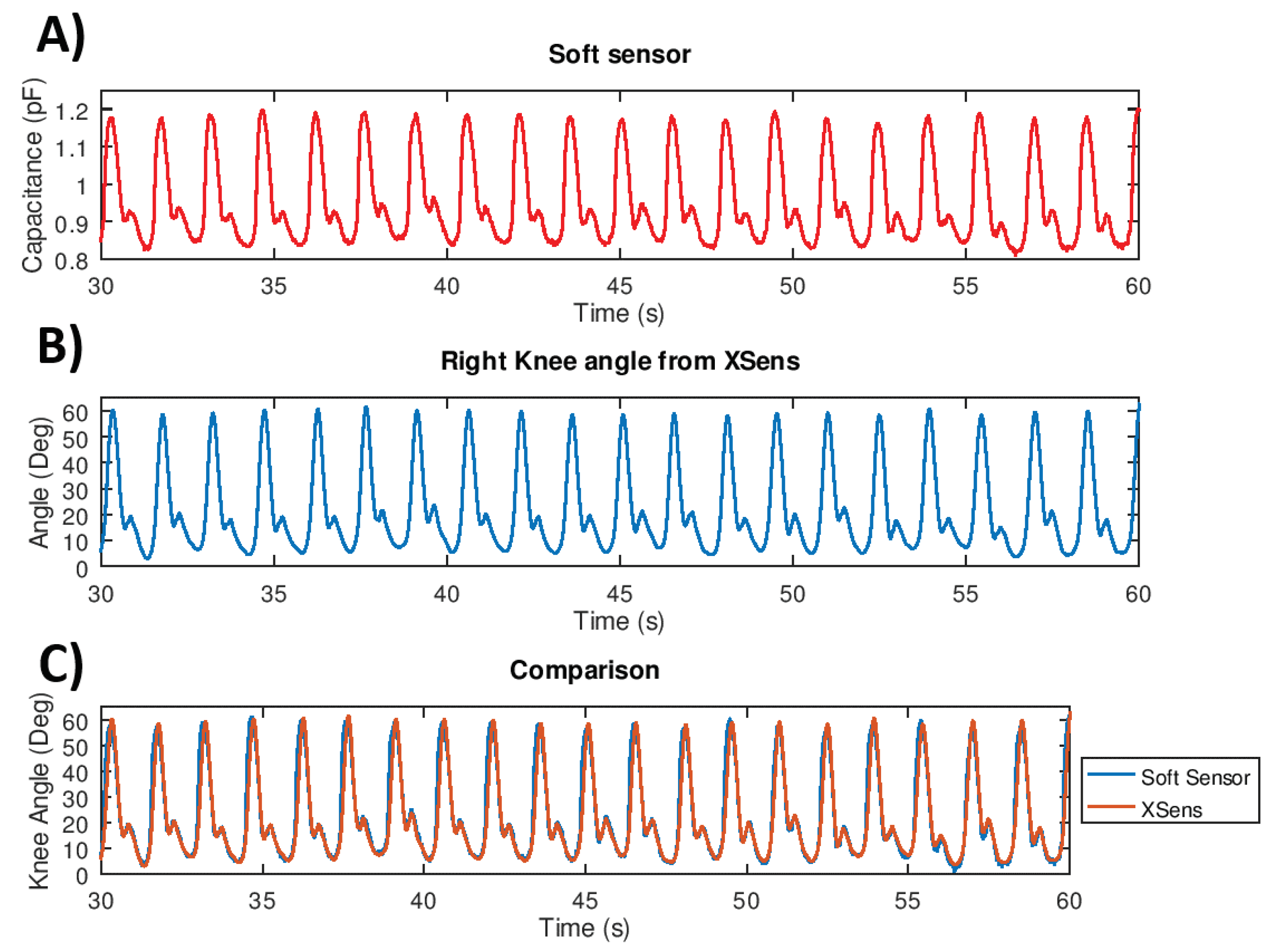
3.1.1. Lab Validation of the Soft Sensor Technology

The main objective of this validation is to insert the soft sensors in the control loop of the exosuit and, in particular, to use the information provided by them during the swing phase. It can be observed that, compared to previous versions, the signal amplitude is much higher, and the swing phase can also be easily recognized from raw data.
During these trials, the whole XoSoft Gamma exosuit was worn by a healthy subject who walked on a treadmill for 5 min at constant speed of 3 km/h (0.8 m/s). During the tests, motion capture was assessed using the MTw Awinda 3D human wireless tracker (Xsens, Enschede, the Netherlands), which was used in parallel with the soft sensor to capture the joint movements and act as a reference. Figure 6A shows the soft sensor output and the corresponding bending angle measured by the Xsens system (shown in Figure 6B) in a 30-s time window. These data demonstrate a clear correlation between the two signals of the knee angle estimated by both technologies (shown in Figure 6C). Moreover, the system is able to detect both swing and stance knee angle trends. The root mean square error (RMSE) between the reference signal (Xsens) and the estimated angle (soft sensing) is around 3.1 ± 1.2 .
Based on these results, we concluded that the soft sensing system is suitable for use in the control loop of the exosuit, and that it is able to measure the knee bending angle with accuracy that is broadly comparable to commercial tracking systems, but requires low computational effort and is more portable.

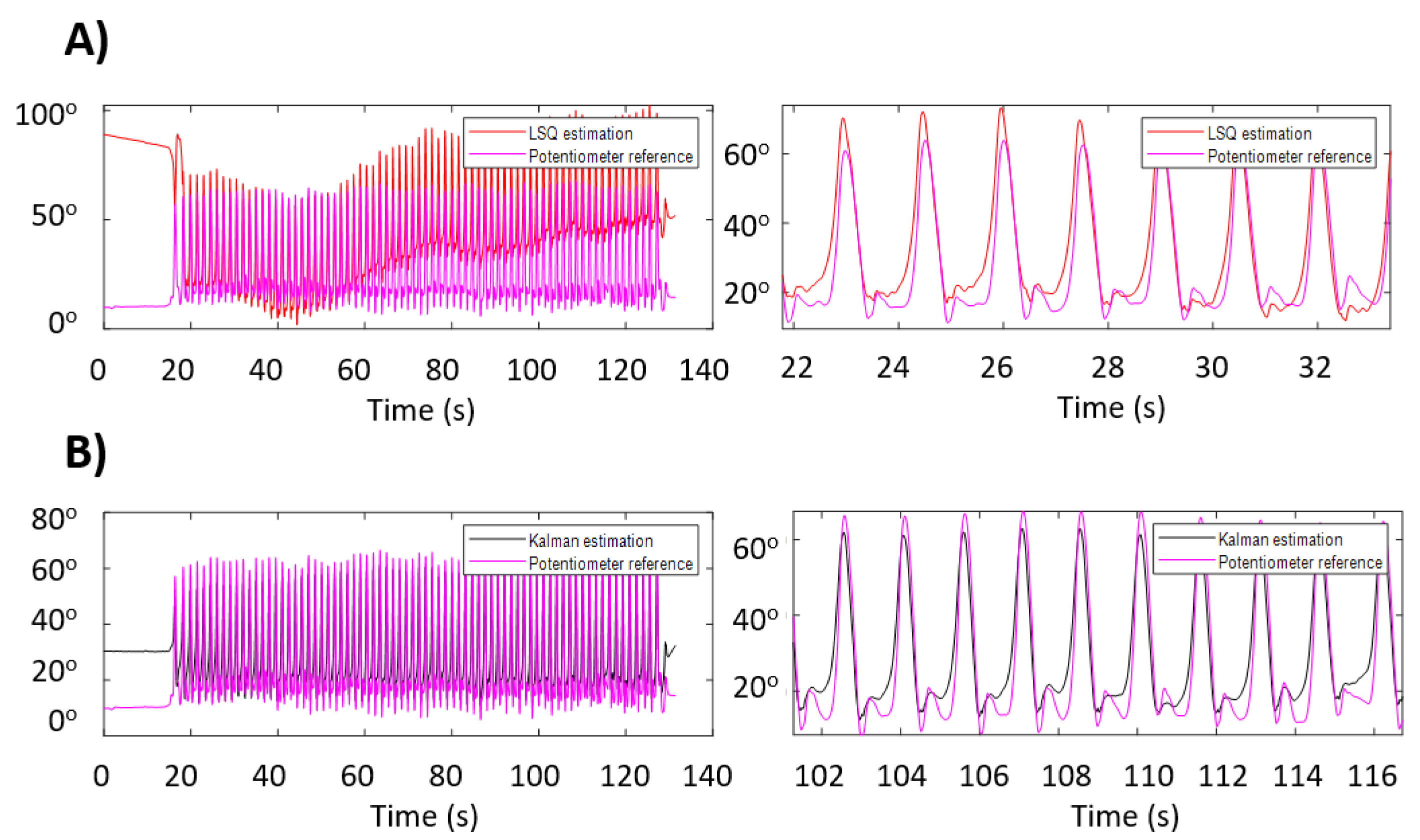
3.1.2. Lab Validation of IMUs Sensor Technology

The IMU-based knee angle measurement system has been assessed with a healthy subject walking on a treadmill (3 km/h) and compared against an orthosis equipped with a potentiometer to extract knee angle references [94]. The IMUs were directly mounted on the user’s legs and both algorithms (i.e., LSQ and EKF) were run in real-time. Figure 7A,B, show taht the EKF gives very good angle estimate, removing at the same time the drift from the signal. The estimation of the RMSE of the LSQ algorithm is 7.5 ± 1.8 after the removal of the drift with the use of the Matlab detrend function. The estimated drift has a linear rate of 0.65 / s (after 100 s the measurement is off by about 65 ). The absolute error of the EKF based estimation is 5.6 ± 5 with no drift. During these experiments, the magnitude of the angles measured with the potentiometer differ from those computed with the IMUs. This difference is due to the relative movement between the leg and the exosuit because of the flexibility of the attachments. In conclusion, even if the error is not very low ( 5 error over a maximum range of motion (RoM) of about 50 ), the EKF based algorithm allow the use of the IMU technology for the specific scope.

3.2. Overall Assessment

3.2.1. Experimental Protocol

One healthy subject (male, 30 years old, 1.7 m tall, 70 kg) was recruited in the study. These tests were conducted in a controlled laboratory environment compliant with the experimental protocol approved by the Ethics Committee of Liguria, Italy (protocol number: 001/2019). The subject performed five couples of walking tasks wearing the Xosoft Gamma exosuit (described in Section 2.2) and without wearing it (reference condition). Before starting to walk on a treadmill, the subject performed isometric maximal voluntary contraction (MVC) three times for each investigated muscle, according to SENIAM recommendations (Hermens et al. 2000). The order of each walking tasks conditions (with and without the exosuit) was chosen randomly for each of the five testing days, a short period to recover from fatigue was taken between each consecutive run. The walking tests were conducted on a treadmill at a constant speed of 3 km/h (0.8 m/s) for a total duration of three minutes in each instance.
During each test, the participant’s fully-body kinematics, lower limb surface electromyography (EMG) and the exosuit’s on-board sensors were recorded. The data from the three sensors (kinematic data, EMG data and exosuit’s data) were synchronized. An Xsens wearable motion tracking system was used (MTw Awinda 3D Wireless Motion Tracker, Xsens Technologies B.V. Enschede, The Netherlands) at a sampling rate of 100 Hz to acquire full-body kinematics. An 8-channel Wi-Fi transmission surface electromyograph (FreeEMG300 System, BTS, Milan, Italy) was used to acquire the surface myoelectric signals at a sampling rate of 1000 Hz. After skin preparation, bipolar Ag/AgCl surface electrodes (diameter 2 cm), prepared with electroconductive gel, were placed over the muscle belly in the direction of the muscle fibers (distance of 2 cm between the centres of the electrodes) according to the European recommendations for surface electromyography [97] and the atlas of muscle innervation zones [98]. Four bipolar electrodes were placed bilaterally on the vastus lateralis (VL) and the biceps femoris (BF) because of their role as knee extensors and flexors, respectively. More in detail, both on left and right lower limbs, the probes on VL, deputy for the knee extension, were placed at 2/3 on the line from the anterior spina iliaca superior to the lateral side of the patella, while the electrodes on BF, which is responsible for flexion and lateral rotation of the knee joint, were placed at 50% on the line between the ischial tuberosity and the lateral epicondyle of the tibia as specified in the SENIAM’s Recommended sensor placement procedure [99].

3.2.2. EMG Data Analysis

Data were processed using MATLAB software (MATLAB 9.7.0, MathWorks, Natick, MA, USA). The raw EMG signals were band-pass filtered using a zero-lag third order Butterworth filter (20–450 Hz), rectified, and low-pass filtered with a zero-lag fourth order Butterworth filter (10 Hz). The time scale was normalized by interpolating individual gait cycles over 1200 points. Then, the EMG signal from each muscle was normalized to the MVC peak value across all trials. We considered 234 gait cycles for each session (with/without the exosuit).
To investigate the effect of the exosuit on muscle fatigue, the co-activation, the root mean square (RMS) and the mean frequency (MF) of the power spectrum of the EMG signals were calculated. For each stride, the co-activation has been evaluated through the time varying multi muscle co-activation function (TMCf), which was assessed between the knee antagonist muscles using the following formula proposed by [100]:
T M C f ( d ( i ) , i ) = 1 1 1 + exp ( 12 ( d ( i ) 0.5 ) ) ( m = 1 M E M G m ( i ) / M ) 2 m a x m = 1 M [ E M G m ( i ) ]
where M is the number of considered muscles, E M G m ( i ) is the i-th sample of the EMG value of the m th muscle, d ( i ) is the mean of the differences between muscles signals at sample i:
d ( i ) = m = 1 M n = m + 1 M | E M G m ( i ) E M G n ( i ) | M ! / ( 2 ! ( M 2 ) ! )
This method provides a sample-by-sample estimate of the relative activation of the pair of muscles. With the use of this equation, high co-contraction values represent a high level of activation of both muscles across a large time interval, while low co-contraction values indicate either low level activation of one muscle along with low-level activation of the other muscle in the pair [100]. To have a global measure of the coactivity level as a co-activation index (CI), the TMCf was then averaged over the entire stride cycle (i = 1:N, where N is the number of samples per stride, 1200 samples). For each stride, the RMS was computed over the interval ranging from 5 % to 70 % of the gait cycle for the VL muscle and from 60 % to 100 % of the stride cycle for the BF and over the entire gait cycle, according to the following formula:
R M S = 1 N i = 1 N E M G i 2
where E M G i is the value of the i-th sample of the envelope of each muscle and N is the number of samples of each interval. For each muscle and each stride, the MF was computed as the ratio between the spectral moments of order 1 and 0 [101,102]:
M F = t 1 t 2 f P S D ( f ) δ f t 1 t 2 P S D ( f ) δ f
where t 1 and t 2 are the initial and final instants of each stride, P S D ( f ) is the power spectrum density of the EMG signal, and f is the frequency.
The statistical analysis was performed using SPSS 20.0 software (IBM). p-values < 0.05 were considered statistically significant. We used the Shapiro-Wilk test [103] to verify that the data was from a normal distribution, then we applied a parametric paired t-test to detect any significant differences in the CI and in the RMS and MF for each muscle between an average of 230 strides for each test repetitions in the condition in which the subject was not wearing the exosuit and same number of strides was considered when the subject was wearing it. A priori power analysis using the G*Power computer program [104] indicated that a total sample of 54 strides would be enough to detect medium effects ( d = 0.5 ) with 95% power using a paired t-test between means with α = 0.05 .

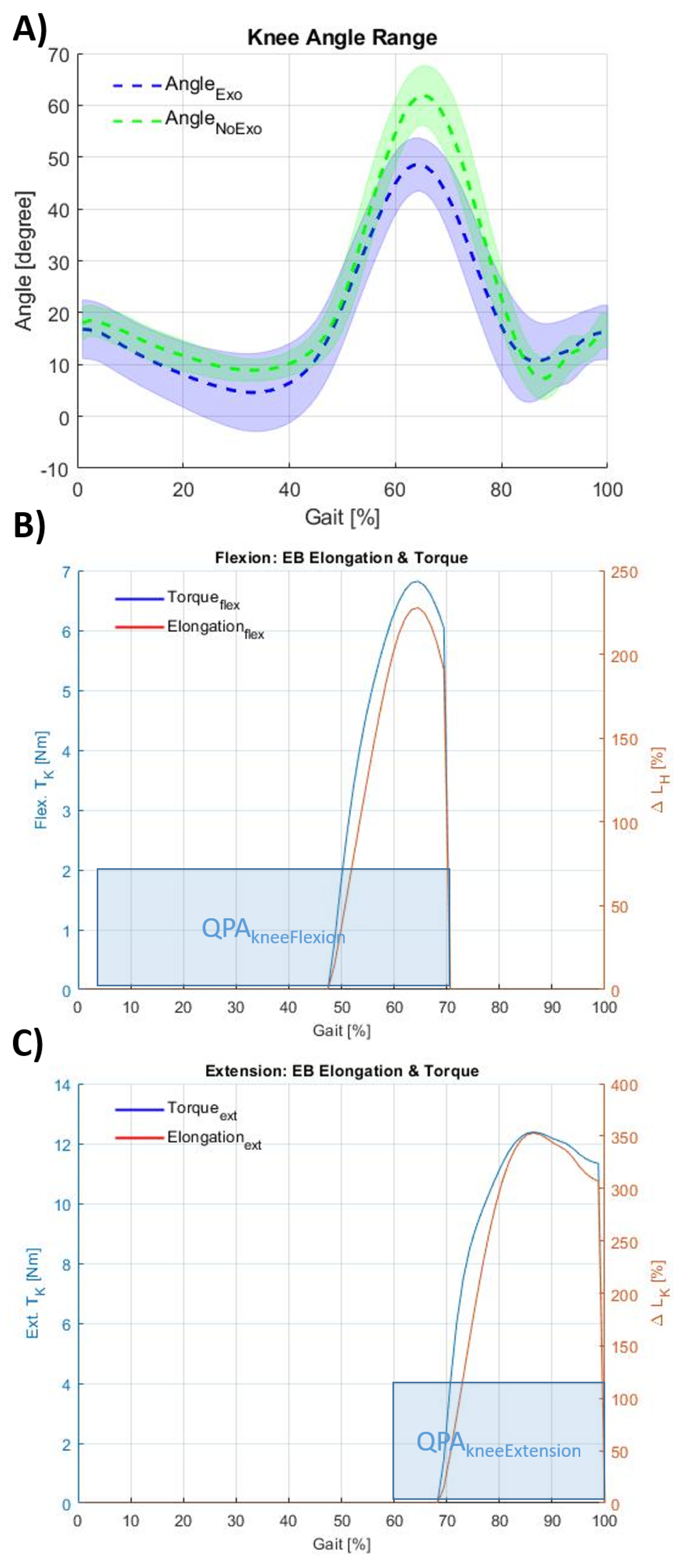
3.2.3. Kinematic Assessment Results

Joint angles were calculated, and displayed as in Figure 8A, based on the standards defined by the International Society of Biomechanics [105]. All kinematic data were plotted from 0 % to 100 % of gait cycle ( 0 % = touch-down of heel, 100 % = consecutive touch-down of the same heel). The estimate of the effective assistance provided by each actuator module (i.e., Q P A k n e e F l e x i o n , Q P A k n e e E x t e n s i o n ) worn by the subject is reported in Figure 8B,C. As previously mentioned, the Q P A k n e e F l e x i o n is activated between 5 % and 70 % of the gait cycle and the Q P A k n e e E x t e n s i o n is activated between 60 % and 100 % of the gait cycle. The effective elongation and torque generated by each actuator is also a function of the knee angle, thus, the final elongation trend starts later along the gait cycle with respect to each engagement event (shown in Figure 8B,C). The final abrupt drop of the torque is due to the system disengagement which is done deliberating to dissipate the potential elastic energy. Figure 8A shows the knee angles, averaged between right and left leg during the five walking tasks with ( A n g l e E x o ), and without the exosuit ( A n g l e N o E x o ). The vertical line represents the toe off point for each cycle corresponding with the swing starting event. The figure shows how the exoskeleton modifies the trajectory of the knee joint reducing both flexion (between 50–80% of gait cycle) and extension angles (between 80–100% of gait cycle), which is due to the effect of the resistive force generated by the exosuit. Figure 8B,C represent the calculated torque and the elastic band elongation as a function of the joint angle, based on the Equation (2) presented in Section 2.2.1 and validated in [24]. The RoM without the exosuit is 54.6 ± 8.0 , and with the exosuit it is 44.0 ± 9.0 , which corresponds to a reduction of 10.6 . The Peak Knee Flexion (PKF) angle in the sagittal is plane calculated as the maximum flexion angle within the gait cycle and is 61.9 ± 5.3 without and 48.6 ± 4.7 with the exosuit. These results show that the joint angle is affected by the use of the exosuit, in particular both RoM and PKF are reduced. Physiologically, the knee flexion should be greater than 40 with a knee RoM between 40 and 50 , specifically a flexion less than 40 inadequately prepares the limb for swing [106,107,108]. Although the reduction of both RoM and PKF are about 10 and 13 respectively, the user is still able to accomplish the walking task with no increase in the risk of tripping due to the knee flexion reduction. In addition, the RoM remains large enough to allow the exosuit to work properly.

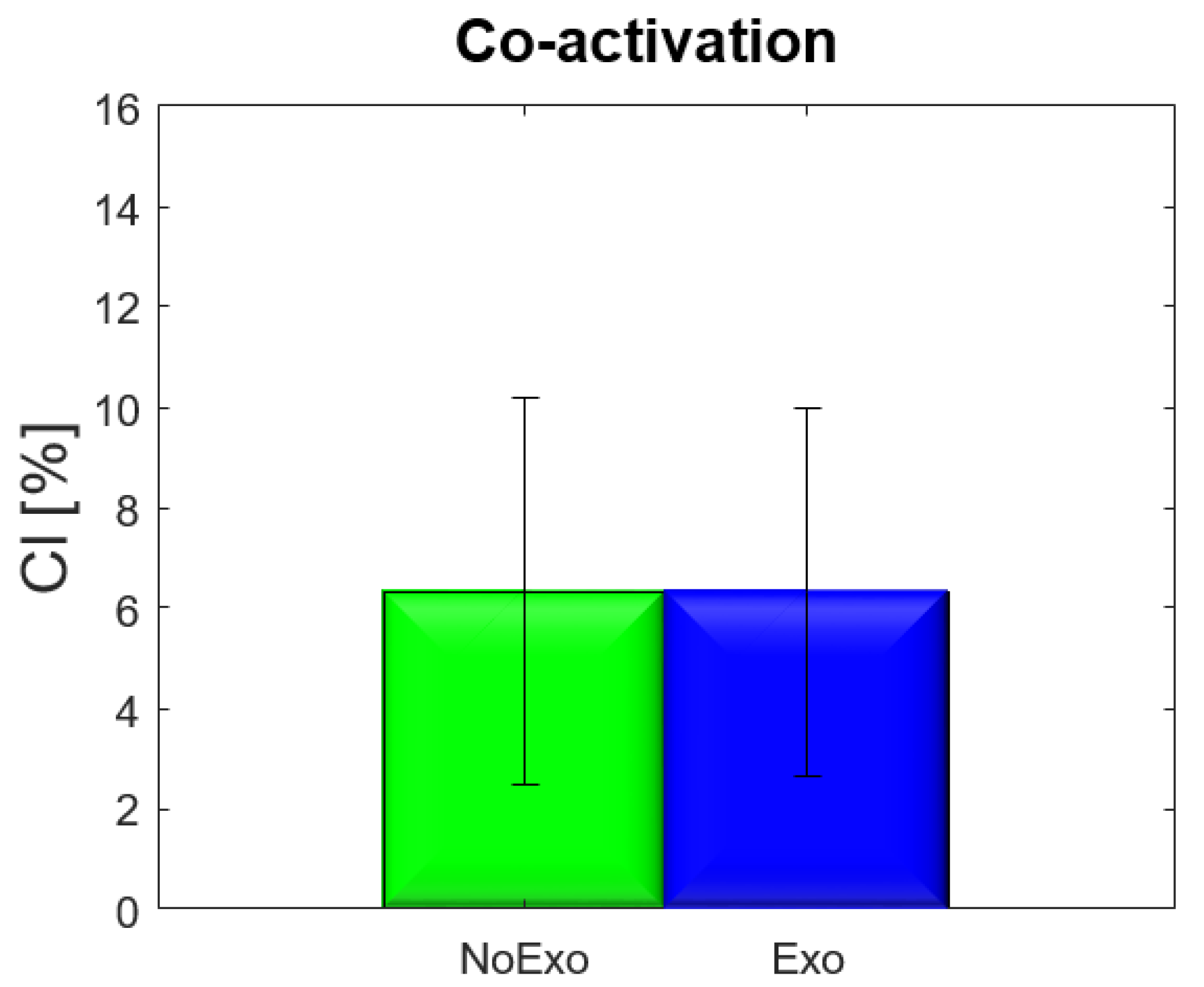
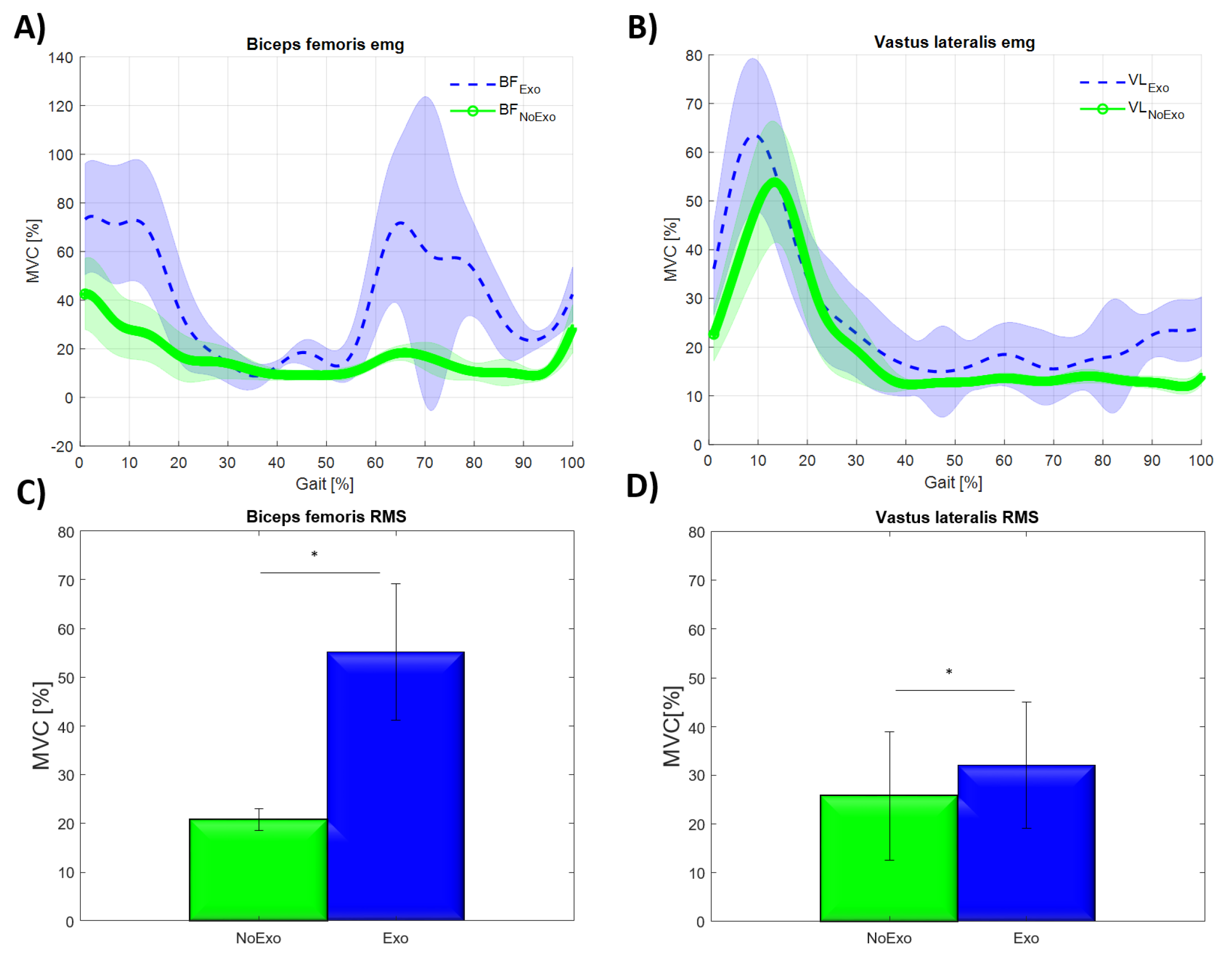
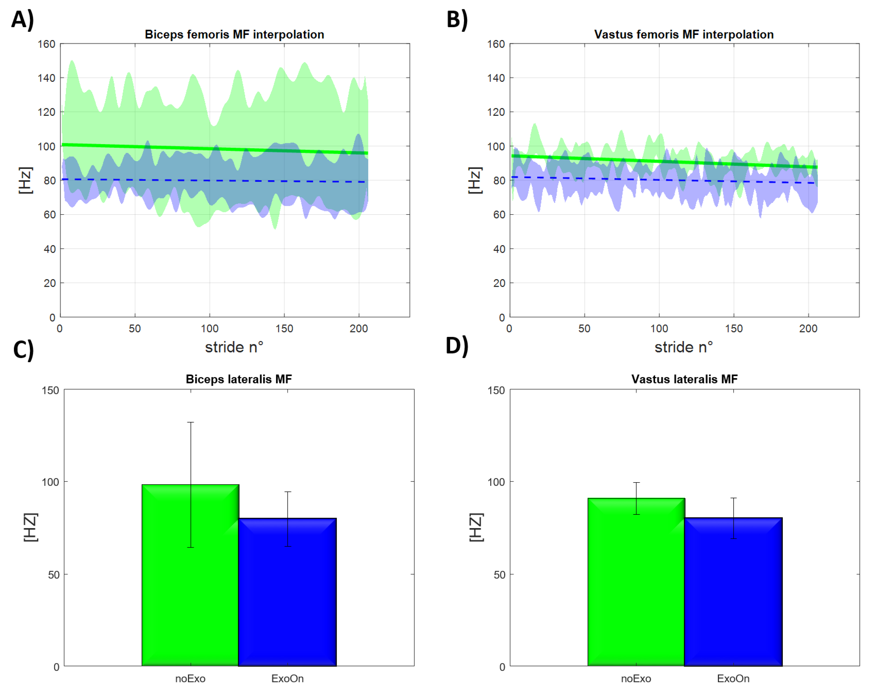
3.2.4. EMG Assessment Results

The t-test revealed a not significant difference in the Co-activation Index (CI) with and without wearing the exosuit ( t = 0.04 , p = 0.295 ) , as shown in Figure 9, (both values show a CI of 6.3%). Figure 9 shows the invariance of CI, which is a global index of muscle activation, providing a confirmation that walking with this resistive exosuit does not provide significant modification of the walking pattern.
The RMS of both VL and BF, averaged over five tests with and without the exosuit showed a significant increase at the paired t-test ( V L : t = 22.923 ,   p < 0.001 ; B F : t = 15.052 ,   p < 0.001 ) , while the MF showed a significant decrease at the paired t-test ( V L : t = 25.888 ,   p < 0.001 ;   B F : t = 12.723 ,   p < 0.001 ) . Figure 10 shows the mean, over five tests of the RMS, SD and significant differences. Figure 11 illustrates the mean of the MF signal (averaged over five repetitions), SD and significant differences.
The EMG assessment results show that the use of the exosuit causes muscle fatigue both in the BF and VL muscles. The increase in RMS reflects the rise in muscle activity during the whole gait cycle, for both the BF and VL, when wearing the exosuit. This is showed in Figure 10A,B. The RMS, computed over the entire stride for each muscle while wearing the exosuit increases by 167.1 % ± 72.1 % for the BF (from 20.8 % ± 12.2 % to 55.2 % ± 13.9 % of MVC), and by 28.4 % ± 16.8 % for the VL (from 25.8 % ± 13.2 % to 32.1 % ± 12 KF.9% of MVC). The difference in the increase of the RMS between the BF and VL is attributed to the resistive effect of the exosuit, that offers contrary forces to the user motion during both knee flexion and extension, thus, resulting in the need for greater effort from the knee flexors and extensors muscle groups.
A further confirmation that the exosuit produces muscle fatigue comes from the power spectrum analysis. Figure 11A shows the trend for the MF with the number of strides. The MF of the BF, with the exosuit, is lower than the testing configuration without the exosuit. In all configurations the trend of the MF is negative, thus, as the number of strides increase, the MF further reduces. A similar behavior is for the the MF of the VL (shown in Figure 11B), where as the subject continues walking, the MF decreases. The MF reduces by 18.9 % (from 98.4 ± 33.4 Hz to 79.8 ± 14.8 Hz) for the BF and by 11.9 % for the VL (from 90.9 ± 8.6 Hz to 80.1 ± 10.9 Hz). This confirms that the main change in the EMG signal in the frequency domain is the translation of the spectrum towards lower frequencies [109]. The difference in the rate of reduction of the MF for the BF and VL reinforces the previously advanced hypothesis that this resistive exosuit, although fatiguing both BF and VL, requires a greater effort on the extensor and flexor muscles.

4. Discussion & Limitations

The resistive exosuit presented and assessed in this work (results are summarized in Table 1) is able to increase the muscular activity of both extensor and flexor muscles of the knees. The main goal of this work has been the quantification of the resistance generated by the modular actuation (i.e., QPA) on a single joint in bilateral configuration (i.e., right and left knee) during a simple and repetitive task (i.e., walking task). The study aimed, thus, to show the increment of fatigue required to accomplish a standard cyclical task to about its double value of muscular fatigue when accomplish terrestrial tasks. This could be interpreted as the ability for the exosuit to recreate the same fatigue required by the type of activities performed on land. The analysis and results on muscular activation and power spectrum sustain the hypothesis. In particular, the mean muscular activation overall increases of about an 97.8 % of the MVC, while considering the mean of the two muscles (BF 167.1 % , and VL 28.4 % ). Transferring this consideration to absolute values, the resistive exosuit can almost replicate the typical muscular effort generated during walking task (the typical effort would be totally replicated with an overall muscular activation increment of 100 % ).
The power spectrum analysis shows that, even if the walking task is not a demanding task, therefore, muscle fatigue does not arise after 3 min, if the resistive exosuit is worn, the user’s muscles perceive muscular fatigue. Although the short duration of the test, the clear results show a reduced value of MFs for both muscles underlining that even for an easy task (i.e., walking task), thanks to the exosuit, it turns into a more demanding task. Indeed, an overall average of MF reduction for both muscles of about 15.4 % (BF 18.9 % and VL 11.9 % ) is higher than what was demonstrated and assessed in [101], where the average MF reduction obtained after 10 min running activity was 7.5 % ( 5 % for the soleus muscle and 10 % for the gastrocnemius medialis). Dimitrov et al. [102] evaluated the maximum range of MF reduction for set of muscles if subjected to high demanding task. They reported an experimental assessment where knee-extension MVC was performed against 120 kg weight, where the maximal change of median spectral frequency observed was 32 % on rectus femoris muscles. Thus, confirming that the exosuit, on earth, is able to intensify fatigue by generating a muscular fatigue comparable to long-term running or physical exercise in general. This result may imply that in a zero-gravity environment this exosuit could induce a level of fatigue included between the fatigue of walking and running. Considering that, the final target is to use the exosuit at micro-gravity as muscle degradation countermeasure by modifying the training paradigm. These preliminary results start building evidence that continuous training could substitute concentrate training as micro-gravity countermeasure with potential equal benefits.
The use of QPA, constituted by a passive element (i.e., EBs), which is the unique fundamental element for the generation of resistive forces, and a clutch to modulate these forces by engaging and disengaging such generation, allows the control and maximization of these resistive forces. In particular, after the EB elongation due to the user’s joint motion, the specific deactivation timing of the clutch prevents from the release of the mechanical energy stored into the elongated EB (such behavior is shown in Figure 8B,C). In case such mechanical energy would be released the exosuit would assist the user motion [24]. Moreover, the particular exosuit design (i.e., soft, light and modular) contributes to increase the comfort and acceptability of the technology for a prolonged usage. Thus, the exosuit structure and actuation typology presented and assessed, constitutes a suitable solution for a training exosuit as a countermeasure for side-effects due to long flight at micro-gravity.
Due to the encouraging results, the presented exosuit (XoSoft Gamma prototype) can be a starting platform for developing suitable solutions for micro-gravity environments. Presently, the main concern is about the clutch actuation which relies on both electric and vacuum. The actuator technology should allow a very low power consumption to enable long working time without the need to recharge batteries often. A low consumption single supply clutch (e.g., electric powered) would be better for this typology of applications. Regarding sensors, micro-gravity might affect some of them that would not work as on Earth. In particular, the current Gamma prototype relies also on insole sensors and IMUs. The astronauts would float in the space craft because of micro-gravity, then ground force sensors are not suitable solution to control the exosuit. Similarly, the joint angle measurement based on IMU technology and traditional algorithms are not reliable on space since earth gravity vector is not perceived and earth magnetic field is reduced in intensity and continuously changing due to the motion in orbit around the Earth. Thus, specific IMU-based algorithms should be developed and assessed for working on micro-gravity. In contrast, soft sensors, used also to measure joint angles, performed very well and their operation is not affected by space environment features or required sophisticated algorithms to enable their usage. Thus, allowing the use of soft sensors without the need to adopt precautions. In conclusion, the current control strategy of the Gamma prototype is specifically developed for walking tasks. The finite state machine and gait segmentation allow the user to program the control of QPAs to produce assistance or resistance accordingly with the cyclical gait motion execution. In space, the scenario is completely different, since the astronauts do not have a characteristic cyclical pattern that allow them to move from place to place and they fluctuate and help their motion within the spacecraft by grabbing handles and pushing or pulling their self by using both arms and legs. Thus, a specific control strategy must be developed for being suitable at micro-gravity.

5. Conclusions

We performed the assessment of the resistive exosuit with QPA and specific sensors strategy during five repetitions of walking tasks by analyzing the effects on gait kinematics, muscular activation and muscular fatigue. The subsystem and overall validations underline that the actuation typology (QPA) and soft sensor technology perform well and are very promising even if considering the challenge offered by the space environment. While a statistically relevant study was outside the scope of this preliminary assessment study, these results are very promising and point toward positive findings overall. The results of this study, which underline an effective increase in both muscular activation and muscular fatigue, confirm the ability of exosuit to significantly increase the muscular effort necessary to perform simple cyclical and repetitive tasks. This implies that in zero gravity the same swing of the knees may require a fatigue comparable to that required to walk on earth, thus allowing the use of this device for continuous daily training in micro-gravity. In addition, this study shows a further usage of the XoSoft platform, that apart from gait assistance, it can be used as resistive device for training and physical exercise, particularly for medium and long endurance spaceflights. This preliminary work will prompt further investigation and development targeting the space community and related issues.
Further studies on the resistive exosuit will be conducted to validate the effectiveness of the exosuit on different physical exercises. Further improvements to the exoskeleton will aim to develop a full-body exosuit able to training all the main muscle/joint groupings, sensor solutions to measure a user’s angular joint, control strategies to ensure suitable operations in a micro-gravity environment, and the development of a low energy consumption QPA.

Author Contributions

Conceptualization, C.D.N.; methodology, C.D.N.; software, C.D.N., M.T. and J.S.L.-M.; validation, C.D.N., G.C. and M.T.; formal analysis, C.D.N. and G.C.; investigation, C.D.N.; resources, D.G.C. and G.V.; data curation, C.D.N. and G.C.; writing—original draft preparation, C.D.N.; writing—review and editing, C.D.N., G.C., M.T. and D.G.C.; visualization, C.D.N., G.C. and M.T.; supervision, L.B., E.R. and J.O.; project administration, J.O. All authors have read and agreed to the published version of the manuscript.

Funding

This work has received funding from the European Union’s Horizon 2020 framework programme for research and innovation under grant agreement No 688175; and the European Space Agency (ESA). J.S.L.M. was in receipt of a Training Program for Academic Staff fellowship (FPU16/01313) by the Ministry of Universities of the Government of Spain.

Institutional Review Board Statement

The study was conducted according to the guidelines of the Declaration of Helsinki, and these tests are complied with the experimental protocol approved by the Ethical Committee of Liguria, Italy, 8 October 2019, protocol number: 001/2019.

Informed Consent Statement

Informed consent was obtained from all subjects involved in the study.

Conflicts of Interest

The authors declare no conflict of interest.

Abbreviations

The following abbreviations are used in this manuscript:
EMGelettromiografia
COLBERTCombined Operational Load Bearing External Resistance Treadmills
ISSInternational Space Station
iREDinterim Resistive Exercise Device
AREDAdvanced Resistive Exercise Device
CEVIScycle egometer
METSmetabolic equivalent of task
QPAQuasi-passive Actuation
HRIHuman-Robot Interaction
EBElastic Band
SCSoft Clutch
HSheel strike
FlFflat foot
FrFfront foot
TOtoe off
PSIpositive speed inflection
NSInegative speed inflection
HSheel pressure signal
OSoutside insole pressure signal
ISinside insole pressure signal
TStoe pressure signal
KADknee angular displacement
IMUinertial measurement unit
LSQLeast Square method
EKFextended kalman filter
RMSEroot mean square error
MVCmaximal voluntary contraction
BFbiceps femoris
VLvastus lateralis
MFmean frequency
TMCftime varying multi muscle co-activation function
CIco-activation index
RoMrange of motion
PKFPeak Knee Flexion

References

  1. Smith, M., Jr.; Rambaut, P.; Vogel, J.; Whittle, M. Bone mineral measurement: Experiment M078. In Biomedical Results from Skylab (NASA SP-377); National Aeronautics and Space Administration: Washington, DC, USA, 1977; pp. 183–190. [Google Scholar]
  2. Lang, T.; LeBlanc, A.; Evans, H.; Lu, Y.; Genant, H.; Yu, A. Cortical and trabecular bone mineral loss from the spine and hip in long-duration spaceflight. J. Bone Miner. Res. 2004, 19, 1006–1012. [Google Scholar] [CrossRef]
  3. Smith, S.M.; Wastney, M.E.; O’Brien, K.O.; Morukov, B.V.; Larina, I.M.; Abrams, S.A.; Davis-Street, J.E.; Oganov, V.; Shackelford, L.C. Bone markers, calcium metabolism, and calcium kinetics during extended-duration space flight on the Mir space station. J. Bone Miner. Res. 2005, 20, 208–218. [Google Scholar] [CrossRef] [Green Version]
  4. Sibonga, J.D.; Cavanagh, P.R.; Lang, T.F.; LeBlanc, A.D.; Schneider, V.S.; Shackelford, L.C.; Smith, S.M.; Vico, L. Adaptation of the skeletal system during long-duration spaceflight. Clin. Rev. Bone Miner. Metab. 2007, 5, 249–261. [Google Scholar] [CrossRef] [Green Version]
  5. LeBlanc, A.D.; Spector, E.R.; Evans, H.J.; Sibonga, J.D. Skeletal responses to space flight and the bed rest analog: A review. J. Musculoskelet. Neuronal Interact. 2007, 7, 33. [Google Scholar]
  6. Fitts, R.H.; Riley, D.R.; Widrick, J.J. Functional and structural adaptations of skeletal muscle to microgravity. J. Exp. Biol. 2001, 204, 3201–3208. [Google Scholar] [PubMed]
  7. Fitts, R.H.; Riley, D.R.; Widrick, J.J. Physiology of a microgravity environment invited review: Microgravity and skeletal muscle. J. Appl. Physiol. 2000, 89, 823–839. [Google Scholar] [CrossRef] [PubMed] [Green Version]
  8. Smith, S.M.; Heer, M.A.; Shackelford, L.C.; Sibonga, J.D.; Ploutz-Snyder, L.; Zwart, S.R. Benefits for bone from resistance exercise and nutrition in long-duration spaceflight: Evidence from biochemistry and densitometry. J. Bone Miner. Res. 2012, 27, 1896–1906. [Google Scholar] [CrossRef] [PubMed]
  9. Cavanagh, P.R.; Licata, A.A.; Rice, A.J. Exercise and pharmacological countermeasures for bone loss during longduration space flight. Gravit. Space Res. 2007, 18, 39–58. [Google Scholar]
  10. Carpinelli, R.N. Exercise countermeasure to weightlessness during manned spaceflight. Med. Sport. 2014, 18, 42–44. [Google Scholar] [CrossRef]
  11. Schneider, S.M.; Amonette, W.E.; Blazine, K.; Bentley, J.; Lee, S.; Loehr, J.A.; Moore, J.A.; Rapley, M.; Mulder, E.R.; Smith, S.M. Training with the International Space Station interim resistive exercise device. Med. Sci. Sport. Exerc. 2003, 35, 1935–1945. [Google Scholar] [CrossRef] [PubMed]
  12. Loehr, J.A.; Lee, S.M.; English, K.L.; Sibonga, J.; Smith, S.M.; Spiering, B.A.; Hagan, R.D. Musculoskeletal adaptations to training with the advanced resistive exercise device. Med. Sci. Sport. Exerc. 2011, 43, 146–156. [Google Scholar] [CrossRef] [PubMed]
  13. Trappe, S.; Costill, D.; Gallagher, P.; Creer, A.; Peters, J.R.; Evans, H.; Riley, D.A.; Fitts, R.H. Exercise in space: Human skeletal muscle after 6 months aboard the International Space Station. J. Appl. Physiol. 2009. [Google Scholar] [CrossRef] [PubMed] [Green Version]
  14. Ainsworth, B.E.; Haskell, W.L.; Whitt, M.C.; Irwin, M.L.; Swartz, A.M.; Strath, S.J.; O Brien, W.L.; Bassett, D.R.; Schmitz, K.H.; Emplaincourt, P.O.; et al. Compendium of physical activities: An update of activity codes and MET intensities. Med. Sci. Sport. Exerc. 2000, 32, S498–S504. [Google Scholar] [CrossRef] [PubMed] [Green Version]
  15. Rea, R.; Beck, C.; Rovekamp, R.; Neuhaus, P.; Diftler, M. X1: A robotic exoskeleton for in-space countermeasures and dynamometry. In Proceedings of the AIAA Space 2013 Conference and Exposition, San Diego, CA, USA, 12 September 2013; p. 5510. [Google Scholar]
  16. Jezernik, S.; Colombo, G.; Keller, T.; Frueh, H.; Morari, M. Robotic orthosis lokomat: A rehabilitation and research tool. Neuromodul. Technol. Neural Interface 2003, 6, 108–115. [Google Scholar] [CrossRef]
  17. Veneman, J.F.; Kruidhof, R.; Hekman, E.E.; Ekkelenkamp, R.; Van Asseldonk, E.H.; Van Der Kooij, H. Design and evaluation of the LOPES exoskeleton robot for interactive gait rehabilitation. IEEE Trans. Neural Syst. Rehabil. Eng. 2007, 15, 379–386. [Google Scholar] [CrossRef] [Green Version]
  18. Farris, R.J.; Quintero, H.A.; Goldfarb, M. Preliminary evaluation of a powered lower limb orthosis to aid walking in paraplegic individuals. IEEE Trans. Neural Syst. Rehabil. Eng. 2011, 19, 652–659. [Google Scholar] [CrossRef] [Green Version]
  19. Murray, S.A.; Ha, K.H.; Goldfarb, M. An assistive controller for a lower-limb exoskeleton for rehabilitation after stroke, and preliminary assessment thereof. In Proceedings of the 2014 36th Annual International Conference of the IEEE Engineering in Medicine and Biology Society, Chicago, IL, USA, 26–30 August 2014; pp. 4083–4086. [Google Scholar]
  20. Awad, L.N.; Bae, J.; O’donnell, K.; De Rossi, S.M.; Hendron, K.; Sloot, L.H.; Kudzia, P.; Allen, S.; Holt, K.G.; Ellis, T.D.; et al. A soft robotic exosuit improves walking in patients after stroke. Sci. Transl. Med. 2017, 9, eaai9084. [Google Scholar] [CrossRef] [Green Version]
  21. Jin, S.; Iwamoto, N.; Hashimoto, K.; Yamamoto, M. Experimental evaluation of energy efficiency for a soft wearable robotic suit. IEEE Trans. Neural Syst. Rehabil. Eng. 2017, 25, 1192–1201. [Google Scholar] [CrossRef]
  22. Schmidt, K.; Duarte, J.E.; Grimmer, M.; Sancho-Puchades, A.; Wei, H.; Easthope, C.S.; Riener, R. The Myosuit: Bi-articular anti-gravity exosuit that reduces hip extensor activity in sitting transfers. Front. Neurorobot. 2017, 11, 57. [Google Scholar] [CrossRef] [Green Version]
  23. Di Natali, C.; Poliero, T.; Sposito, M.; Graf, E.; Bauer, C.; Pauli, C.; Bottenberg, E.; De Eyto, A.; O’Sullivan, L.; Hidalgo, A.F.; et al. Design and Evaluation of a Soft Assistive Lower Limb Exoskeleton. Robotica 2019, 37, 2014–2034. [Google Scholar] [CrossRef] [Green Version]
  24. Di Natali, C.; Sadeghi, A.; Mondini, A.; Bottenberg, E.; Hartigan, B.; De Eyto, A.; O’Sullivan, L.; Rocon, E.; Stadler, K.; Mazzolai, B.; et al. Pneumatic Quasi-Passive Actuation For Soft Assistive Lower Limbs Exoskeleton. Front. Neurorobot. 2020, 14, 31. [Google Scholar] [CrossRef] [PubMed]
  25. Sadeghi, A.; Mondini, A.; Totaro, M.; Mazzolai, B.; Beccai, L. A Wearable Sensory Textile-Based Clutch with High Blocking Force. Adv. Eng. Mater. 2019, 21, 1900886. [Google Scholar] [CrossRef]
  26. Graf, E.S.; Bauer, C.M.; Power, V.; de Eyto, A.; Bottenberg, E.; Poliero, T.; Sposito, M.; Scherly, D.; Henke, R.; Pauli, C.; et al. Basic functionality of a prototype wearable assistive soft exoskeleton for people with gait impairments: A case study. In Proceedings of the 11th PErvasive Technologies Related to Assistive Environments Conference, Corfu, Greece, 26–29 June 2018; pp. 202–207. [Google Scholar]
  27. Sposito, M.; Poliero, T.; Di Natali, C.; Ortiz, J.; Pauli, C.; Graf, E.; De Eyto, A.; Bottenberg, E.; Caldwell, D. Evaluation of XoSoft Beta-1 lower limb exoskeleton on a post stroke patient. In Proceedings of the Sixth National Congress of Bioengineering, Milan, Italy, 25–27 June 2018. [Google Scholar]
  28. Shore, L.; Power, V.; Hartigan, B.; Schülein, S.; Graf, E.; de Eyto, A.; O’Sullivan, L. Exoscore: A design tool to evaluate factors associated with technology acceptance of soft lower limb exosuits by older adults. Hum. Factors 2020, 62, 391–410. [Google Scholar] [CrossRef]
  29. Graf, E.; Bauer, C.; Schülein, S.; de Eyto, A.; Power, V.; Bottenberg, E.; Weyermann, B.; O’Sullivan, L.; Wirz, M. Assessing usability of a prototype soft exoskeleton by involving people with gait impairments. In Proceedings of the WCPT World Confederation for Physical Therapy Congress, Geneva, Switzerland, 10–13 May 2019; ZHAW Zürcher Hochschule für Angewandte Wissenschaften: Winterthur, Switzerland, 2019. [Google Scholar]
  30. Tanimoto, M.; Ishii, N. Effects of low-intensity resistance exercise with slow movement and tonic force generation on muscular function in young men. J. Appl. Physiol. 2006, 100, 1150–1157. [Google Scholar] [CrossRef] [Green Version]
  31. Westcott, W.L.; Winett, R.A.; Anderson, E.S.; Wojcik, J.R. Effects of regular and slow speed resistance training on muscle strength. J. Sport. Med. Phys. Fit. 2001, 41, 154. [Google Scholar]
  32. Hansen, D.; Dendale, P.; Jonkers, R.; Beelen, M.; Manders, R.; Corluy, L.; Mullens, A.; Berger, J.; Meeusen, R.; Van Loon, L. Continuous low-to moderate-intensity exercise training is as effective as moderate-to high-intensity exercise training at lowering blood HbA 1c in obese type 2 diabetes patients. Diabetologia 2009, 52, 1789–1797. [Google Scholar] [CrossRef] [Green Version]
  33. Evans, C.H., Jr.; Ball, J.R. Behavioral health and performance. In Safe Passage: Astronaut Care for Exploration Missions; National Academies Press (US): Washington, DC, USA, 2001. [Google Scholar]
  34. Wolf, S.; Grioli, G.; Eiberger, O.; Friedl, W.; Grebenstein, M.; Höppner, H.; Burdet, E.; Caldwell, D.G.; Carloni, R.; Catalano, M.G.; et al. Variable stiffness actuators: Review on design and components. IEEE/ASME Trans. Mechatron. 2016, 21, 2418–2430. [Google Scholar] [CrossRef]
  35. Van Ham, R.; Sugar, T.G.; Vanderborght, B.; Hollander, K.W.; Lefeber, D. Compliant actuator designs. IEEE Robot. Autom. Mag. 2009, 3, 81–94. [Google Scholar]
  36. Manti, M.; Cacucciolo, V.; Cianchetti, M. Stiffening in soft robotics: A review of the state of the art. IEEE Robot. Autom. Mag. 2016, 23, 93–106. [Google Scholar] [CrossRef]
  37. Caldwell, D.G.; Tsagarakis, N.G.; Kousidou, S.; Costa, N.; Sarakoglou, I. “SOFT” exoskeletons for upper and lower body rehabilitation—Design, control and testing. Int. J. Hum. Robot. 2007, 4, 549–573. [Google Scholar] [CrossRef]
  38. Kesner, S.B.; Jentoft, L.; Hammond, F.L.; Howe, R.D.; Popovic, M. Design considerations for an active soft orthotic system for shoulder rehabilitation. In Proceedings of the 2011 Annual International Conference of the IEEE Engineering in Medicine and Biology Society, Boston, MA, USA, 30 August–3 September 2011; pp. 8130–8134. [Google Scholar]
  39. Asbeck, A.T.; De Rossi, S.M.; Galiana, I.; Ding, Y.; Walsh, C.J. Stronger, smarter, softer: Next-generation wearable robots. IEEE Robot. Autom. Mag. 2014, 21, 22–33. [Google Scholar] [CrossRef]
  40. Taghavi, M.; Helps, T.; Huang, B.; Rossiter, J. 3D-printed ready-to-use variable-stiffness structures. IEEE Robot. Autom. Lett. 2018, 3, 2402–2407. [Google Scholar] [CrossRef]
  41. Alkan, M.S.; Gurocak, H.; Gonenc, B. Linear magnetorheological brake with serpentine flux path as a high force and low off-state friction actuator for haptics. J. Intell. Mater. Syst. Struct. 2013, 24, 1699–1713. [Google Scholar] [CrossRef]
  42. Nikitczuk, J.; Weinberg, B.; Canavan, P.K.; Mavroidis, C. Active knee rehabilitation orthotic device with variable damping characteristics implemented via an electrorheological fluid. IEEE/ASME Trans. Mechatronics 2010, 15, 952–960. [Google Scholar] [CrossRef]
  43. Diller, S.; Majidi, C.; Collins, S.H. A lightweight, low-power electroadhesive clutch and spring for exoskeleton actuation. In Proceedings of the 2016 IEEE International Conference on Robotics and Automation (ICRA), Stockholm, Sweden, 16–21 May 2016; pp. 682–689. [Google Scholar]
  44. Ramachandran, V.; Shintake, J.; Floreano, D. All-Fabric Wearable Electroadhesive Clutch. Adv. Mater. Technol. 2019, 4, 1800313. [Google Scholar] [CrossRef]
  45. Zubrycki, I.; Granosik, G. Novel haptic device using jamming principle for providing kinaesthetic feedback in glove-based control interface. J. Intell. Robot. Syst. 2017, 85, 413–429. [Google Scholar] [CrossRef] [Green Version]
  46. Walsh, C.J.; Endo, K.; Herr, H. A quasi-passive leg exoskeleton for load-carrying augmentation. Int. J. Hum. Robot. 2007, 4, 487–506. [Google Scholar] [CrossRef]
  47. Van Dijk, W.; Van der Kooij, H.; Hekman, E. A passive exoskeleton with artificial tendons: Design and experimental evaluation. In Proceedings of the 2011 IEEE International Conference on Rehabilitation Robotics, Zurich, Switzerland, 29 June–1 July 2011; pp. 1–6. [Google Scholar]
  48. Sasaki, D.; Noritsugu, T.; Takaiwa, M. Development of pneumatic lower limb power assist wear driven with wearable air supply system. In Proceedings of the 2013 IEEE/RSJ International Conference on Intelligent Robots and Systems, Tokyo, Japan, 3–7 November 2013; pp. 4440–4445. [Google Scholar]
  49. Brown, E.; Rodenberg, N.; Amend, J.; Mozeika, A.; Steltz, E.; Zakin, M.R.; Lipson, H.; Jaeger, H.M. Universal robotic gripper based on the jamming of granular material. Proc. Natl. Acad. Sci. USA 2010, 107, 18809–18814. [Google Scholar] [CrossRef] [Green Version]
  50. Jiang, A.; Xynogalas, G.; Dasgupta, P.; Althoefer, K.; Nanayakkara, T. Design of a variable stiffness flexible manipulator with composite granular jamming and membrane coupling. In Proceedings of the 2012 IEEE/RSJ International Conference on Intelligent Robots and Systems, Vilamoura-Algarve, Portugal, 7–12 October 2012; pp. 2922–2927. [Google Scholar]
  51. Follmer, S.; Leithinger, D.; Olwal, A.; Cheng, N.; Ishii, H. Jamming user interfaces: Programmable particle stiffness and sensing for malleable and shape-changing devices. In Proceedings of the 25th Annual ACM Symposium on User Interface Software and Technology, Cambridge, MA, USA, 7–10 October 2012; pp. 519–528. [Google Scholar]
  52. Stanley, A.A.; Gwilliam, J.C.; Okamura, A.M. Haptic jamming: A deformable geometry, variable stiffness tactile display using pneumatics and particle jamming. In Proceedings of the World Haptics Conference (WHC), Daejeon, Korea, 14–17 April 2013; pp. 25–30. [Google Scholar]
  53. Li, M.; Ranzani, T.; Sareh, S.; Seneviratne, L.D.; Dasgupta, P.; Wurdemann, H.A.; Althoefer, K. Multi-fingered haptic palpation utilizing granular jamming stiffness feedback actuators. Smart Mater. Struct. 2014, 23, 095007. [Google Scholar] [CrossRef]
  54. Sadeghi, A.; Mondini, A.; Mazzolai, B. Preliminary Experimental Study on Variable Stiffness Structures Based on Textile Jamming for Wearable Robotics. In Proceedings of the International Symposium on Wearable Robotics, Pisa, Italy, 16–20 October 2018; Springer: Berlin Germany, 2018; pp. 49–52. [Google Scholar]
  55. Mengüç, Y.; Park, Y.L.; Pei, H.; Vogt, D.; Aubin, P.M.; Winchell, E.; Fluke, L.; Stirling, L.; Wood, R.J.; Walsh, C.J. Wearable soft sensing suit for human gait measurement. Int. J. Robot. Res. 2014, 33, 1748–1764. [Google Scholar] [CrossRef]
  56. Souri, H.; Banerjee, H.; Jusufi, A.; Radacsi, N.; Stokes, A.A.; Park, I.; Sitti, M.; Amjadi, M. Wearable and Stretchable Strain Sensors: Materials, Sensing Mechanisms, and Applications. Adv. Intell. Syst. 2020, 2, 2000039. [Google Scholar] [CrossRef]
  57. Chortos, A.; Liu, J.; Bao, Z. Pursuing prosthetic electronic skin. Nat. Mater. 2016, 15, 937–950. [Google Scholar] [CrossRef]
  58. Yogeswaran, N.; Dang, W.; Navaraj, W.T.; Shakthivel, D.; Khan, S.; Polat, E.O.; Gupta, S.; Heidari, H.; Kaboli, M.; Lorenzelli, L.; et al. New materials and advances in making electronic skin for interactive robots. Adv. Robot. 2015, 29, 1359–1373. [Google Scholar] [CrossRef] [Green Version]
  59. Yang, T.; Xie, D.; Li, Z.; Zhu, H. Recent advances in wearable tactile sensors: Materials, sensing mechanisms, and device performance. Mater. Sci. Eng. R Rep. 2017, 115, 1–37. [Google Scholar] [CrossRef]
  60. Tiwana, M.I.; Redmond, S.J.; Lovell, N.H. A review of tactile sensing technologies with applications in biomedical engineering. Sens. Actuators A Phys. 2012, 179, 17–31. [Google Scholar] [CrossRef]
  61. Stassi, S.; Cauda, V.; Canavese, G.; Pirri, C.F. Flexible tactile sensing based on piezoresistive composites: A review. Sensors 2014, 14, 5296–5332. [Google Scholar] [CrossRef] [Green Version]
  62. Salim, A.; Lim, S. Review of recent inkjet-printed capacitive tactile sensors. Sensors 2017, 17, 2593. [Google Scholar] [CrossRef] [PubMed] [Green Version]
  63. Wang, H.; Totaro, M.; Beccai, L. Toward perceptive soft robots: Progress and challenges. Adv. Sci. 2018, 5, 1800541. [Google Scholar] [CrossRef]
  64. Ivančo, J.; Halahovets, Y.; Végsö, K.; Klačková, I.; Kotlár, M.; Vojtko, A.; Micuśík, M.; Jergel, M.; Majková, E. Cyclopean gauge factor of the strain-resistance transduction of indium oxide films. IOP Conf. Ser. Mater. Sci. Eng. 2016, 108, 012043. [Google Scholar] [CrossRef] [Green Version]
  65. Tian, H.; Shu, Y.; Cui, Y.L.; Mi, W.T.; Yang, Y.; Xie, D.; Ren, T.L. Scalable fabrication of high-performance and flexible graphene strain sensors. Nanoscale 2014, 6, 699–705. [Google Scholar] [CrossRef]
  66. Yamada, T.; Hayamizu, Y.; Yamamoto, Y.; Yomogida, Y.; Izadi-Najafabadi, A.; Futaba, D.N.; Hata, K. A stretchable carbon nanotube strain sensor for human-motion detection. Nat. Nanotechnol. 2011, 6, 296. [Google Scholar] [CrossRef]
  67. Viry, L.; Levi, A.; Totaro, M.; Mondini, A.; Mattoli, V.; Mazzolai, B.; Beccai, L. Flexible three-axial force sensor for soft and highly sensitive artificial touch. Adv. Mater. 2014, 26, 2659–2664. [Google Scholar] [CrossRef] [Green Version]
  68. Atalay, A.; Sanchez, V.; Atalay, O.; Vogt, D.M.; Haufe, F.; Wood, R.J.; Walsh, C.J. Batch fabrication of customizable silicone-textile composite capacitive strain sensors for human motion tracking. Adv. Mater. Technol. 2017, 2, 1700136. [Google Scholar] [CrossRef] [Green Version]
  69. White, E.L.; Yuen, M.C.; Case, J.C.; Kramer, R.K. Low-Cost, Facile, and Scalable Manufacturing of Capacitive Sensors for Soft Systems. Adv. Mater. Technol. 2017, 2, 1700072. [Google Scholar] [CrossRef]
  70. Zhao, H.; O’Brien, K.; Li, S.; Shepherd, R.F. Optoelectronically innervated soft prosthetic hand via stretchable optical waveguides. Sci. Robot. 2016, 1, eaai7529. [Google Scholar] [CrossRef] [PubMed] [Green Version]
  71. Yun, S.; Park, S.; Park, B.; Kim, Y.; Park, S.K.; Nam, S.; Kyung, K.U. Polymer-waveguide-based flexible tactile sensor array for dynamic response. Adv. Mater. 2014, 26, 4474–4480. [Google Scholar] [CrossRef] [PubMed]
  72. Lazarus, N.; Bedair, S.S. Bubble inductors: Pneumatic tuning of a stretchable inductor. AIP Adv. 2018, 8, 056601. [Google Scholar] [CrossRef]
  73. Felt, W.; Chin, K.Y.; Remy, C.D. Smart braid feedback for the closed-loop control of soft robotic systems. Soft Robot. 2017, 4, 261–273. [Google Scholar] [CrossRef]
  74. Wang, H.; Kow, J.; Raske, N.; De Boer, G.; Ghajari, M.; Hewson, R.; Alazmani, A.; Culmer, P. Robust and high-performance soft inductive tactile sensors based on the Eddy-current effect. Sens. Actuators A Phys. 2018, 271, 44–52. [Google Scholar] [CrossRef]
  75. Wang, H.; Totaro, M.; Beccai, L. Development of Fully Shielded Soft Inductive Tactile Sensors. In Proceedings of the 2019 26th IEEE International Conference on Electronics, Circuits and Systems (ICECS), Genoa, Italy, 27–29 November 2019; pp. 246–249. [Google Scholar]
  76. Rocon, E.; Pons, J.L. Exoskeletons in Rehabilitation Robotics: Tremor Suppression; Springer: Berlin, Germany, 2011; Volume 69. [Google Scholar]
  77. Naruse, K.; Kawai, S.; Yokoi, H.; Kakazu, Y. Development of wearable exoskeleton power assist system for lower back support. In Proceedings of the 2003 IEEE/RSJ International Conference on Intelligent Robots and Systems (IROS 2003)(Cat. No. 03CH37453), Las Vegas, NV, USA, 27–31 October 2003; IEEE: Piscataway, NJ, USA, 2003; Volume 4, pp. 3630–3635. [Google Scholar]
  78. Chen, B.; Lanotte, F.; Grazi, L.; Vitiello, N.; Crea, S. Classification of lifting techniques for application of a robotic hip exoskeleton. Sensors 2019, 19, 963. [Google Scholar] [CrossRef] [Green Version]
  79. Cevzar, M.; Petrič, T.; Jamšek, M.; Babič, J. Real-time control of quasi-active hip exoskeleton based on gaussian mixture model approach. In Wearable Robotics: Challenges and Trends, Proceedings of the International Symposium on Wearable Robotics, Pisa, Italy, 16–20 October 2018; Springer: Berlin, Germany, 2018; pp. 244–248. [Google Scholar]
  80. Poliero, T.; Toxiri, S.; Anastasi, S.; Monica, L.; Ortiz, D.G.C.J. Assessment of an On-board Classifier for Activity Recognition on an Active Back-Support Exoskeleton. In Proceedings of the 2019 IEEE 16th International Conference on Rehabilitation Robotics (ICORR), Toronto, ON, Canada, 24–28 June 2019; pp. 559–564. [Google Scholar]
  81. Singh, R.M.; Chatterji, S.; Kumar, A. Trends and challenges in EMG based control scheme of exoskeleton robots-a review. Int. J. Sci. Eng. Res. 2012, 3, 933–940. [Google Scholar]
  82. Gopura, R.; Bandara, D.; Gunasekara, J.; Jayawardane, T. Recent trends in EMG-Based control methods for assistive robots. Electrodiagnosis New Front. Clin. Res. 2013, 237–268. [Google Scholar]
  83. Bi, L.; Guan, C.; Aberham. A review on EMG-based motor intention prediction of continuous human upper limb motion for human-robot collaboration. Biomed. Signal Process. Control. 2019, 51, 113–127. [Google Scholar] [CrossRef]
  84. Chen, J.; Damiano, D.L.; Lerner, Z.F.; Bulea, T.C. Validating Model-Based Prediction of Biological Knee Moment during Walking with an Exoskeleton in Crouch Gait: Potential Application for Exoskeleton Control. In Proceedings of the 2019 IEEE 16th International Conference on Rehabilitation Robotics (ICORR), Toronto, ON, Canada, 24–28 June 2019; pp. 778–783. [Google Scholar]
  85. Proietti, T.; Crocher, V.; Roby-Brami, A.; Jarrasse, N. Upper-limb robotic exoskeletons for neurorehabilitation: A review on control strategies. IEEE Rev. Biomed. Eng. 2016, 9, 4–14. [Google Scholar] [CrossRef] [PubMed] [Green Version]
  86. Yan, T.; Cempini, M.; Oddo, C.M.; Vitiello, N. Review of assistive strategies in powered lower-limb orthoses and exoskeletons. Robot. Auton. Syst. 2015, 64, 120–136. [Google Scholar] [CrossRef]
  87. XoSoft. European Project. 2016–2019. Available online: https://www.xosoft.eu/ (accessed on 15 April 2021).
  88. Sadeghi, A.; Mondini, A.; Mazzolai, B. A Vacuum Powered Soft Textile-Based Clutch. Actuators 2019, 8, 47. [Google Scholar] [CrossRef] [Green Version]
  89. Endo, K.; Paluska, D.; Herr, H. A quasi-passive model of human leg function in level-ground walking. In Proceedings of the 2006 IEEE/RSJ International Conference on Intelligent Robots and Systems, Beijing, China, 9–15 October 2006; pp. 4935–4939. [Google Scholar]
  90. De Rossi, S.M.; Crea, S.; Donati, M.; Reberšek, P.; Novak, D.; Vitiello, N.; Lenzi, T.; Podobnik, J.; Munih, M.; Carrozza, M.C. Gait segmentation using bipedal foot pressure patterns. Poceedings of the 2012 4th IEEE RAS & EMBS International Conference on Biomedical Robotics and Biomechatronics (BioRob), Rome, Italy, 24–27 June 2012; pp. 361–366. [Google Scholar]
  91. Totaro, M.; Poliero, T.; Mondini, A.; Lucarotti, C.; Cairoli, G.; Ortiz, J.; Beccai, L. Soft Smart Garments for Lower Limb Joint Position Analysis. Sensors 2017, 17, 2314. [Google Scholar] [CrossRef]
  92. Picerno, P.; Cereatti, A.; Cappozzo, A. Joint kinematics estimate using wearable inertial and magnetic sensing modules. Gait Posture 2008, 28, 588–595. [Google Scholar] [CrossRef]
  93. Kok, M.; Hol, J.D.; Schön, T.B. Using inertial sensors for position and orientation estimation. arXiv 2017, arXiv:1704.06053. [Google Scholar]
  94. Hidalgo, A.F.; Lora-Millán, J.S.; Rocon, E. IMU-Based Knee Angle Estimation using an Extended Kalman Filter. In Proceedings of the 2019 41st Annual International Conference of the IEEE Engineering in Medicine and Biology Society (EMBC), Berlin, Germany, 23–27 July 2019; pp. 570–573. [Google Scholar]
  95. Seel, T.; Raisch, J.; Schauer, T. IMU-based joint angle measurement for gait analysis. Sensors 2014, 14, 6891–6909. [Google Scholar] [CrossRef] [Green Version]
  96. Roetenberg, D. Inertial and Magnetic Sensing of Human Motion. Ph.D. Thesis, Universiteit Twente, Enschede, The Netherlands, 2006. [Google Scholar]
  97. Hermens, H.J.; Freriks, B.; Disselhorst-Klug, C.; Rau, G. Development of recommendations for SEMG sensors and sensor placement procedures. J. Electromyogr. Kinesiol. 2000, 10, 361–374. [Google Scholar] [CrossRef]
  98. Barbero, M.; Merletti, R.; Rainoldi, A. Atlas of Muscle Innervation Zones: Understanding Surface Electromyography and Its Applications; Springer Science & Business Media: Berlin, Germany, 2012. [Google Scholar]
  99. Stegeman, D.; Hermens, H. Standards for surface electromyography: The European project Surface EMG for non-invasive assessment of muscles (SENIAM). Enschede Roessingh Res. Dev. 2007, 108–112. [Google Scholar]
  100. Ranavolo, A.; Mari, S.; Conte, C.; Serrao, M.; Silvetti, A.; Iavicoli, S.; Draicchio, F. A new muscle co-activation index for biomechanical load evaluation in work activities. Ergonomics 2015, 58, 966–979. [Google Scholar] [CrossRef] [PubMed]
  101. Ament, W.; Bonga, G.J.; Hof, A.L.; Verkerke, G.J. EMG median power frequency in an exhausting exercise. J. Electromyogr. Kinesiol. 1993, 3, 214–220. [Google Scholar] [CrossRef]
  102. Dimitrov, G.V.; Arabadzhiev, T.I.; Mileva, K.N.; Bowtell, J.L.; Crichton, N.; Dimitrova, N.A. Muscle fatigue during dynamic contractions assessed by new spectral indices. Med. Sci. Sport. Exerc. 2006, 38, 1971–1979. [Google Scholar] [CrossRef] [PubMed]
  103. Ghasemi, A.; Zahediasl, S. Normality tests for statistical analysis: A guide for non-statisticians. Int. J. Endocrinol. Metab. 2012, 10, 486. [Google Scholar] [CrossRef] [Green Version]
  104. Faul, F.; Erdfelder, E.; Lang, A.; Buchner, A. A flexible statistical power analysis program for the social, behavioral and biomedical sciences. Behav. Res. Methods 2007, 39, 175–191. [Google Scholar] [CrossRef]
  105. Grood, E.S.; Suntay, W.J. A joint coordinate system for the clinical description of three-dimensional motions: Application to the knee. J. Biomech. Eng. 1983, 105, 136–144. [Google Scholar] [CrossRef]
  106. Perry, J. Normal gait. In AAOS Atlas of Orthoses and Assistive Devices; Hsu, J.D., Michael, J.W., Fisk, J.R., Eds.; Mosby Elsevier: Philadelphia, PE, USA, 2008; pp. 61–82. [Google Scholar]
  107. Brinkmann, J.R.; Perry, J. Rate and range of knee motion during ambulation in healthy and arthritic subjects. Phys. Ther. 1985, 65, 1055–1060. [Google Scholar] [CrossRef] [PubMed]
  108. Serrao, M.; Chini, G.; Casali, C.; Conte, C.; Rinaldi, M.; Ranavolo, A.; Marcotulli, C.; Leonardi, L.; Fragiotta, G.; Bini, F.; et al. Progression of gait ataxia in patients with degenerative cerebellar disorders: A 4-year follow-up study. Cerebellum 2017, 16, 629–637. [Google Scholar] [CrossRef] [PubMed]
  109. Cifrek, M.; Medved, V.; Tonković, S.; Ostojić, S. Surface EMG based muscle fatigue evaluation in biomechanics. Clin. Biomech. 2009, 24, 327–340. [Google Scholar] [CrossRef] [PubMed]
Figure 1. The system overview of the XoSoft Gamma exosuit used during the experimental evaluation. Written informed consent was obtained from the individual pictured in figure.
Applsci 11 03576 g001
Figure 2. Overview of the system components and layout for the “XoSoft Gamma prototype”. The following components form the experimental platform: (1) Xsens and BTS-EMG logging for motion tracking sensors and EMG recording; (2) Logging controller for the exoskeleton state measurement sensors; (3) Air supply; (4) Central processor; (5) Valve controller board; (6) Valves; (7) Soft Clutches (SCs); (8) Shoe sensors; (9) IMUs; (10) Compressed air; (11) Vacuum lines; (12) CAN bus 1; (13) CAN bus 2; (14) Wi-Fi network 1; (15) soft sensors; (16) CAN bus 3; (17) Elastic Bands (EBs). Main hardware components of the exoskeleton are described in Section 2.2.1.
Applsci 11 03576 g002
Figure 3. Control flow of the finite state machine (FSM), in which the events (heel strike, flat foot, front foot, toe off, positive speed inflection and negative speed inflection) determining the state changes are reported.
Applsci 11 03576 g003
Figure 4. Sensing kneepad integrated into the XoSoft exosuit prototype. (A) Schematics of the sensorized kneepad with three embedded capacitive strain sensors. (B) Kneepad with sensors covered by textile patches and with coaxial cables embedded in an elastic sleeve. (C) Raw soft sensor outputs during normal walking tests.
Applsci 11 03576 g004
Figure 5. Arbitrary IMU orientation. T1 and T2 indicate the local frames of IMU1 and IMU2, respectively.
Applsci 11 03576 g005
Figure 6. (A) Soft sensor output. (B) Knee angle measured by the XSens system. (C) Comparison between soft sensors (blue solid line) and XSens system (red solid line), using a linear combination for fitting the knee angle.
Applsci 11 03576 g006
Figure 7. Knee rotation angle by means of the LSQ algorithm (A) and Extended Kalman filter algorithm (B) using the IMUs located on the leg with parallel orientations.
Applsci 11 03576 g007
Figure 8. (A) Knee angle range wearing XoSoft and not wearing XoSoft. (B) Knee flexion resistive torque and EB elongation generated by the XoSoft, and the gait portion when the Q P A k n e e F l e x i o n is engaged. (C) Knee extension resistive torque and EB elongation generated by the XoSoft, and the gait portion when the Q P A k n e e E x t e n s i o n is engaged.
Applsci 11 03576 g008
Figure 9. Mean (bars’ height) and standard deviation (vertical whiskers) of the co-activation index without and with the exoskeleton. The horizontal line with the asterisk denotes a statistically significant difference.
Applsci 11 03576 g009
Figure 10. (A) Biceps femoris activation with and without XoSoft. (B) Vastus lateralis activation with and without XoSoft. (C) Biceps femoris RMS mean (bars’ height), standard deviation (vertical whiskers) with and without the exoskeleton. (D) Vastus lateralis RMS mean (bars’ height), standard deviation (vertical whiskers) with and without the exoskeleton. Both in panels (C,D), the horizontal line with the asterisk denotes a statistically significant difference.
Applsci 11 03576 g010
Figure 11. (A) Biceps femoris MF interpolation with and without XoSoft. (B) Vastus lateralis MF interpolation with and without XoSoft. (C) Biceps femoris MF mean (bars’ height), standard deviation (vertical whiskers) with and without the exoskeleton. (D) Vastus lateralis MF mean (bars’ height), standard deviation (vertical whiskers) with and without the exoskeleton. Both in panels (C,D) the horizontal line with the asterisk denotes a statistically significant difference.
Applsci 11 03576 g011
Table 1. Overall performance: comparison of modalities without the exoskeleton worn (NoExo) and with the resistive exosuit (Exo).
IndexNoExoExoDifference
RoM 54.6 44.6 10
PKF 61.9 48.6 13.3
CI6.3%6.3%0.0
RMS of VL20.8% MVC55.2% MVC34.4% MVC
RMS of BF25.8% MVC32.1% MVC7.3% MVC
MF of VL98.4%79.8%−18.6%
MF of BF90.9%80.1%−10.8%
Publisher’s Note: MDPI stays neutral with regard to jurisdictional claims in published maps and institutional affiliations.

