Article

Check-Valve Design in Enhancing Aerodynamic Performance of Flapping Wings

1
Department of Mechanical and Electromechanical Engineering, Tamkang University, Tamsui 251301, Taiwan
2
Department of Mechanical Engineering, Vel Tech Rangarajan Dr Sagunthala R&D Institute of Science and Technology, Chennai 600062, India
3
School of Electronics and Information Engineering, Beijing Jiaotong University, Beijing 100044, China
4
Yuan Ze Fuel Cell Center, Department of Mechanical Engineering, Yuan Ze University, Taoyuan 32003, Taiwan
*
Author to whom correspondence should be addressed.
Appl. Sci. 2021, 11(8), 3416; https://doi.org/10.3390/app11083416
Submission received: 8 March 2021 / Revised: 4 April 2021 / Accepted: 8 April 2021 / Published: 10 April 2021
(This article belongs to the Special Issue Bioinspired Flight)

Abstract

:
A flapping wing micro air vehicle (FWMAV) demands high lift and thrust generation for a desired payload. In view of this, the present work focuses on a novel way of enhancing the lift characteristics through integrating check-valves in the flapping wing membrane. Modal analysis and static analysis are performed to determine the natural frequency and deformation of the check-valve. Based on the inference, the check-valve opens and closes during the upstroke flapping and downstroke flapping, respectively. Wind tunnel experiments were conducted by considering the two cases of wing design, i.e., with and without a check-valve for various driving voltages, wind speeds and different inclined angles. A 20 cm-wingspan polyethylene terephthalate (PET) membrane wing with two check-valves, composed of central disc-cap with radius of 7.43 mm, supported by three S-beams, actuated by Evans mechanism to have 90° stroke angle, is considered for the 10 gf (gram force) FWMAV study. The aerodynamic performances, such as lift and net thrust for these two cases, are evaluated. The experimental result demonstrates that an average lift of 17 gf is generated for the case where check-valves are attached on the wing membrane to operate at 3.7 V input voltage, 30° inclined angle and 1.5 m/s wind speed. It is inferred that sufficient aerodynamic benefit with 68% of higher lift is attained for the wing membrane incorporated with check-valve.

1. Introduction

Through the research of more than two decades, flapping wing micro air vehicles (FWMAVs) made recently great progress by the control of the tailless configuration. The “Delfly Nimble” [1] and the “KU Beetle” [2] are two successful examples that could perform hovering flight and some distinguished maneuvers. However, based on the flapping wing design improvement by the conventional wind tunnel testing, the forward flight and the level cruising of FWMAVs are still the most primary forms of flapping flight under investigation [3,4,5]. How to reduce the air drag and flight power during cruising, so as to achieve long-term flight endurance, are crucial to the development of FWMAVs [6,7].
Observed from the downstroke and upstroke motions of a full flapping cycle, most of the researchers performed lift enhancement during the downstroke period. There are several ways for lift improvement; for instance, by increasing the wing foil thickness and the camber [8], by adding wing corrugation [9], by enlarging the stroke angle [10], using wing rotation mechanisms [11], using morphing wings [12,13,14], by changing the wing materials [15,16,17], or by adjusting the wing stiffness along the chord-wise/span-wise direction [18]. Not many studies have been performed for the enhancement of lift through mimicking feathers [19,20,21,22,23,24,25] in the upstroke. The adaptive flight control of Caltech’s Microbat by using check valves [23], the Festo’s BionicSwift using of aerodynamic feathers similar to overlapping shingles on the roof [26,27], and the ventilated design [22] are the prominent research works in lift enhancement. Compared to the Caltech’s Mircobat, the wingspan and body mass of Festo’s Bionic Swift and the ventilated design [22,27] is much larger. Based on the more familiar understanding of the 20 cm-span FWMAVs [28,29,30], herein we would like to qualitatively address the validity of the lift enhancement mechanism in Figure 1.
Figure 1a,b illustrate the closing and opening of the check-valve during the downstroke and upstroke, respectively. The valve-opening action can effectively reduce the magnitude of the negative lift since its pin-hole opening spoils both the completeness of the wing and smoothness of the air flow. On the other hand, it also shows that the closing of check-valve during the downstroke completely restores the wing contour. It ensures that the positive lift is similar to the plain membrane wing without valves. The expected lift waveforms are shown in Figure 1c,d. In Figure 1d, dash line is the reference line shown in order to compare the region where the magnitude of the negative lift of the closed check-valve is reduced to a solid line waveform of the open check-valve case. It is evident that the proper opening and closing of the check-valves can enhance the average lift during flapping. However, there are still open issues with reference to the design of check-valves for FWMAVs. The following are limitations in comparing to the existing study [23].
Problem (i): There seems to be no baseline for the size and number of four serpentine (S) arms of the check-valves. Number 4 is not a prime number; thus, resonance may be present in this design.
Problem (ii): Other studies fail to describe the dynamic behavior of the check-valves. Therefore, it is difficult to justify the appropriateness of their design.
Problem (iii): There are too many check-valves distributed at the leading and trailing edges of the flapping wing [31,32]. They will induce many unpredictable issues.
To eliminate these stumbling blocks, a modified design and corresponding experimental studies are conducted. In this work, the check-valve is designed by examining static and dynamic characteristics using finite element analysis (FEA). Wind tunnel experiments are conducted by incorporating the check-valves in the flapping wings and the aerodynamic performance characteristics are measured.

2. Methodology

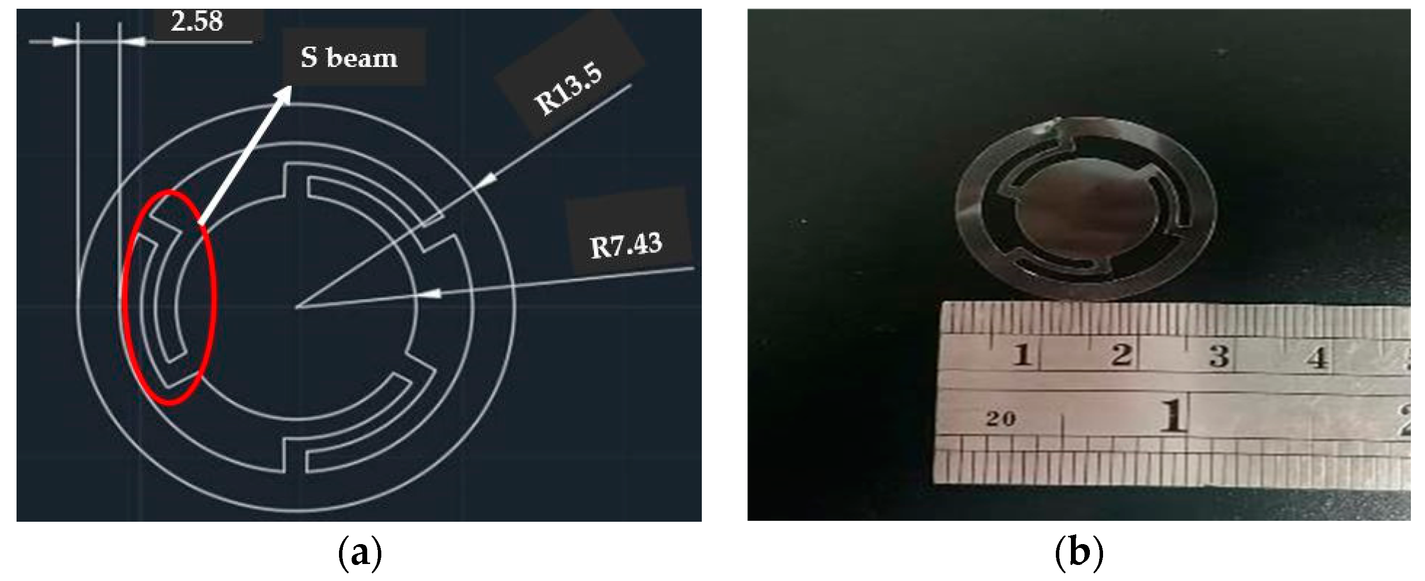
2.1. Design of Check-Valve

The inspiration of check-valve design comes from observing the functionality of a feather in ornithology, reducing the negative lift created by ventilation [22,23]. The feather of the bird acts as a key factor of lift enhancement, and the structure of the feather is too complex to manufacture using traditional processing methods [33]. In this work, we adopted the disc-cap shape with three S beams as the main structure of the check-valve, which is shown in Figure 2a and, hence, the resonance is avoided at the central disc-cap. The annular ring, shown in Figure 2, is fixed on the lower surface of the membrane wing, which has its corresponding pin hole or orifice at the central disc-cap. The deformation of the check-valve during flapping is considered to be a dynamic problem and determining the transient solution is laborious. However, the static solutions are viable enough to perform design optimization instead of performing dynamic analysis. Hence, in this work, finite element analysis is performed for the design of the check-valve, shown in Figure 2b, which is made of PET membrane.

2.2. Frequency Response

In general, the structural dynamics phenomenon is dealt with using the frequency response [34]. Therefore, there is no gain in dB according to the static solution, and the dynamic solution of the disc-cap motion can be reasonably approximated by the static solution of the check-valve disc-cap. The static and modal analyses are performed to determine the deformation and natural frequencies. The natural frequency at the first mode is experienced at 18.90 Hz, subjected to a disc-cap radius of 7.43 mm, which is higher than the flapping frequency 11–14 Hz. The maximum deformation of the disc-cap is designed to be larger than the actual disc radius, ensuring that the valve is effectively opened to enhance the aerodynamic lift.
Static analysis is performed through considering the PET material for the flapping wing membrane and the corresponding mechanical properties are given in Table 1. For the ANSYS simulation, a 3-layer hexahedral mesh with 247,614 elements and 1.25 million nodes is considered to construct the finite element mesh. A simulation result, with a natural frequency of 41.78 Hz, is shown in Figure 3a, subject to a disc-cap radius of 4.95 mm. Figure 3b depicts the static analysis stress distribution, and the maximum stress experienced by the valve is 8.72 MPa and the safety factor (=maximum stress/tensile strength) considered here is 6.3. Table 2 compares the results and significant performance measures of check-valves with different disc-cap radii. There is no natural frequency value for the plain wing as there is not a check-valve attached to it. The natural frequency of the 12 check-valves is high because the size of the radius is smaller than the 2 check-valve cases. The higher natural frequency of the 12 check-valves is reasonably calculated by considering only one check-valve out of 12, which is 0.1 g for each, lighter than the 2-valve case (Table 2, second column). However, the maximum flapping frequency in the fourth column was measured from the whole behavior of wing flapping. It was smaller (6 Hz) in the heavier 12-valve case and larger (14 Hz) in the lighter 2-valve case due to the different weight loading.

2.3. Integration of Check-Valve on the Flapping Wing

The integration of several check-valves on the leading and trailing edges of the wing membrane induces unpredictable aerodynamic phenomena [32]. The multiple and single-pair check-valve arrangements are made of 20 cm-span Evans mechanism-driven FWMAVs, as shown in Figure 4. The arrangement of the single pair of check-valves is modified based on the observation through high-speed photography and the instantaneous position of the central disc-cap, which is shown in Figure 5.

2.4. High Speed Photography

In order to visualize the motion of the check-valves, an infallible method of identification was performed by using a high-speed camera with the capability to capture images at 1000 frames per second. The flapping wing is activated using a DC motor, which is connected to a power supply unit. Figure 5a shows the valve opening at the beginning of the upstroke flapping motion and confirms the functional aspects of the designed check-valve. Figure 5b shows that the central disc-cap deforms (7.39 mm) far away from the hole. Lastly, when the wing starts moving in a downstroke motion, the check-valve is closed, as shown in Figure 5c.
Though both valve designs, given in Table 2, have larger natural frequencies (41.78 Hz for the 4.95 mm disc-cap and 18.90 Hz for the 7.43 mm disc-cap) than the flapping frequency (11–14 Hz for applying different driving voltages), the maximum deformation of the disc-cap has to be verified by performing the experiment. It is observed that the deformation mark in Figure 5b for the disc-cap radius of 7.43 mm is able to influence the surrounding air flow pattern of the check-valve; more so than in the case of the 4.95 mm disc-cap.
From the above results, it is found that a single-pair valve with a 7.43 mm disc-cap provided better performance than the multiple twelve valves with 4.95 mm disc-caps on the flapping wing. The drawback of a multiple (×12) check-valve design is that it weighs more than the single-pair check-valve, as demonstrated in Table 2, and it worsens the lift enhancement, which can lower the effective lift values. To understand the applicability of flapping wings with a check-valve, the valve-switching mechanism is modified, and the corresponding flow field changes from the wing posture using high-speed photography are identified.

2.5. Wind Tunnel Experiment

As the result of natural frequency, wind tunnel experiments can provide tangible proof of the efficiency of valves; however, more evidence is needed to validate the hypothesis about the effectiveness of the check-valve. Though the result of frequency is satisfied, it is difficult to quantify the contribution in enhancing the lift by incorporating the check-valve. The wind tunnel experiment, to measure the lift and net thrust, can be a useful indicator with respect to flapping motion characteristics. The wind tunnel, shown in Figure 6, has a contraction ratio of 6.25 with a test section of 30 cm × 30 cm × 100 cm [3,9,28,29,30]. The wind tunnel experiment was conducted for the two cases with and without check-valves of FWMAV. The following are the testing conditions considered for the present study:
  • Wind speed: 0.5–3.0 m/s;
  • Driving voltage: 3.0 V, 3.4 V and 3.7 V;
  • Inclined angle of the FWMAV: 20°, 30°, 50°, 60° and 70°.

3. Results

3.1. Instantaneous Lift Wave Forms and the Averaged Aerodynamic Forces

The lift data, measured for these two cases with and without check valves, are depicted in Figure 7. The lift waveforms correspond to the flapping wing at an inclined angle of 30° for a 3.7 V driving voltage. It is observed from these plots that the original negative lift parts, shown in Figure 7(a1,b1,c1), are shifted positively, shown in Figure 7(a2,b2,c2), using the check-valve action, which is similar to the lift enhancement principle alluded to in the expected lift waveforms shown in Figure 1. The wind tunnel data are processed in MATLAB software using an LPF (low pass filter) with a noise cut-off frequency of 30 Hz. However, only one set of lift waveforms in Figure 7 is not sufficient to evaluate the overall lift enhancement of the check-valve action. We collected full data of lift and net thrust, according to different testing conditions, and obtained their average values. Figure 8 (without check-valve) and Figure 9 (with check-valve) are plotted by considering the time-average of more than 100 flapping cycles for each data point [3,4].
The lift data are plotted in the left column of Figure 8 and Figure 9, whereas the thrust data, shown in the right column of Figure 8 and Figure 9, are actually termed as the net thrust, which is defined as the thrust subtracting the air drag. From the graph plotted, we can see that the lift values increase and the net thrust values decrease with the increase in wind speed. The lift and net thrust are output from the 6-axis force gauge of the wind tunnel facility, shown in Figure 6. Wind tunnel data provide a reference of predicting the aerodynamic lift of MAVs on the ground. The maximum values, shown in Figure 8 and Figure 9, may not be used in actual steady flight or the cruising state. Whether the lift is being used or not depends on the corresponding net thrust value (restated, net thrust = thrust minus drag.) We often select the data points with zero net thrust to determine the cruising conditions of the FWMAV. Under these conditions, the thrust is equal to air drag and no more acceleration is applied to the FWMAV. The FWMAV will keep flying at a constant cruising speed.
In addition, there is a non-linear hysteresis between the driving voltage and the flapping frequency for the FWMAV [35]. As regards acquiring flapping control, we adopted conditions of driving voltage and the flapping frequency that are accordingly expressed within a range. (The flapping frequency could be reversely obtained with the time-changing signals of lift or thrust.) Thus, the corresponding flapping frequency is not mentioned in the paper.

3.2. Identification of Cruising Condition

The following section describes the procedure used to determine the cruising condition:
  • Select a curve in Figure 8 or Figure 9 with respect to the specific driving voltage and inclined angle;
  • Identify the cruising speed by observing the intercepted point with zero net thrust on the net thrust diagram (marked with or );
  • Find the corresponding cruising lift from the identified condition on the lift diagram (marked with or ).
Table 3 shows the cruising speed and cruising lift values with respect to different driving voltages, various inclined angles for both with and without check valve cases that are for all cruising conditions derived from the aerodynamic data shown in Figure 8 and Figure 9. In the third and fourth column of Table 3, sometimes neither cruising speed nor lift corresponding to the zero net thrust are visible; or, the deduced cruising lift is too small (<10 gf) to support the body weight of the FWMAV (“cannot fly”.) We prepared a remark column which mentions they cannot fly, all negative net thrust, improper trend, and all positive net thrust conditions. The reasons for failure in cruising condition selection are clarified as follows:
  • Improper trend: In the cases of 3.4 V-30° and V-60°, and 3.7 V-50° for the check-valve, the net thrust increases with the increase in wind speed. However, this trend is irrational because, in general, drag increases with wind speed. Hence, the cruising condition is not found.
  • All negative (−) net thrust: In the case of 3.0 V-70° without a check-valve, the net thrust data are all negative. Therefore, neither the intercept of zero net thrust nor the cruising condition can be found. A similar issue also occurs in the case of 3.4 V-20° with the check-valve.
  • All positive (+) net thrust: In the case of 3.4 V-70° with a check-valve, the net thrust data are all positive. Therefore, neither the intercept of zero net thrust nor the cruising condition can be found.
Finally, we identified that, for the case of (3.0 V-30°-1.6 m/s), the check-valve case generates 14 gf lift, which is 27% higher than the 11gf lift of the membrane wing without a check-valve. In addition, for the case of (3.7 V-30°-1.5~1.75 m/s), the check-valve case generates 17 gf lift, which is 68% higher than the 10.1 gf lift of the membrane wing without a check-valve. The corresponding 2D quasi steady COMSOL flow simulation is shown in Figure 10 with a freestream flow speed of 1.6 m/s, a flapping frequency of 14 Hz and a stroke angle of 90° (the total incident velocity is 4.68 m/s). The computational fluid dynamics (CFD) are conducted and the velocity vectors over the airfoil for the inclined angle of 30° (Figure 10a,b) and inclined angle of 90° during the upstroke (Figure 10c) are depicted.

4. Discussion

The following are the major observations and questions which arose from the experimental data:
  • It is evident from the lift waveform that the lift during upstroke presents a positive small value, rather than a negative small value, as shown in Figure 7(a2,b2,c2).
  • At low inclined angles, the average lift and net thrust data of the wind tunnel data, observed in Figure 8 and Figure 9, are unclear with high inclined angles.
  • The average lift and net thrust data of the wind tunnel data, shown in Figure 8 and Figure 9, fluctuate greatly, especially under high wind speeds.
  • With massive wind tunnel data points and test conditions, only a few cruising conditions have better lift gain performance, as shown in Table 3.
  • The small size of the check-valve may not be suitable for smaller flapping wings, as shown in Figure 4a.

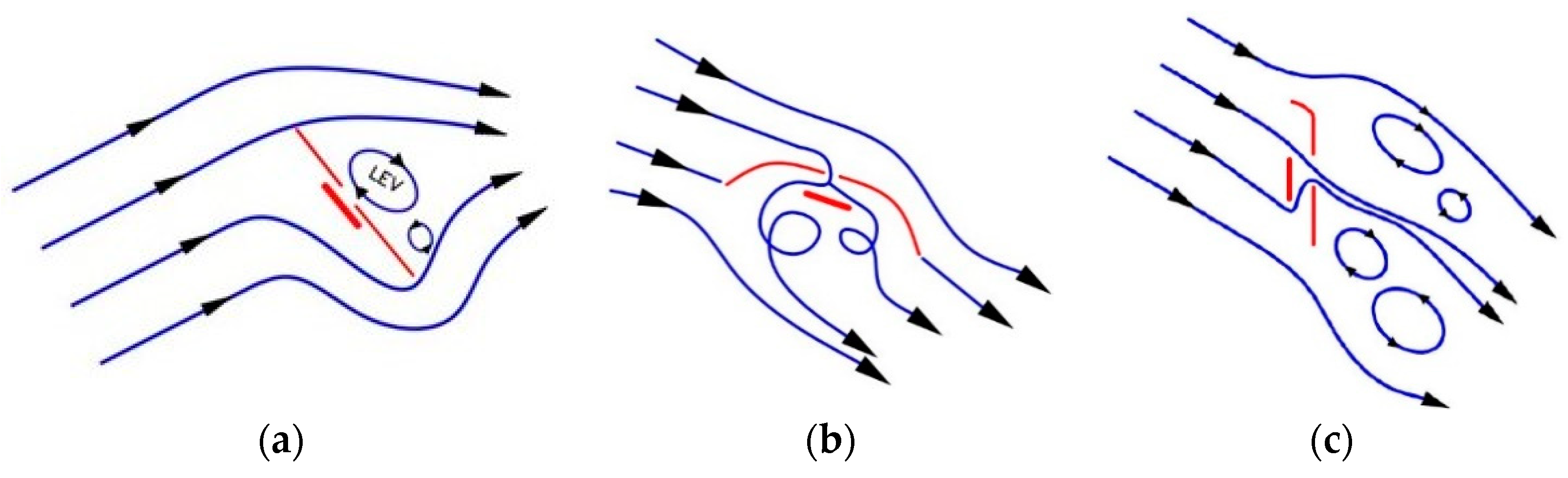
4.1. The Driving Force for Opening the Check-Valve

The check-valve is passive and it need not require external power for opening. In the conceptual design stage, shown in Figure 11a,b, it was initially considered to be the aerodynamic pressure difference that pushed the valve disc-cap open. The direction of air flowing through the valve is designed to flow from the central orifice to the outside of the valve disc-cap, and it opens in during the upstroke period. For this reason, the valve is positioned upside down on the back of the wing membrane, and the inlet air flows from top to bottom during the upstroke. Hence, the valve disc-cap is pushed (open) to adjust the lift. In addition, the valve disc-cap is attached upside down; the assistance of gravity helps with valve opening.
The following are the major observations during valve opening: (1) during the upstroke of the flapping wing, the horizontal free stream and the vertical downward airflow, due to flapping, are combined into a total incident velocity, which blows obliquely downward from the head top and it stops flowing in a purely vertical direction; (2) considering the inclined angle of the wing membrane during the upstroke, the inclined angle of the fuselage during the downstroke is no longer effective, but it is instead a nearly vertical pull-up movement. This can be also verified by high-speed photography. Combining the above two considerations (1) and (2), the position of the valve disc-cap is no longer facing back to the inlet airflow, but instead facing forward to the inlet airflow. The direction of the airflow through the valve in Figure 11b, on the contrary, flows from outside of the valve disc-cap into the central orifice as shown in Figure 11c. It is opened in accordance with the time of upstroke. In turn, this causes the leading-edge vortex (LEV) of the wing to be impacted and broken, reducing the lift value during the upstroke. The flow field is also changed in Figure 11c. An interesting observation is that it was originally thought that the lift of the upstroke should be negative, but the instantaneous angle of attack (AOA) of the wing, relative to the inlet airflow, was positive in Figure 11c. As the LEV intensity is reduced by the orifice jet, there is only a slight positive value. Due to this phenomenon, the lift during the upstroke shows a positive trend instead of a negative one, as shown in Figure 7(a2,b2,c2), which explains the first question.
Due to this, the dominant driving force for opening the check-valve is no longer the aerodynamic pressure difference, but it is the mass inertia of the valve disc-cap itself. When the upstroke starts, the majority of the wing moves upward, but the central valve disc-cap temporarily remains in place due to its mass inertia. The valve is opened until it is largely deformed and pulled up by three S-shaped support beams, and the upstroke ends. When it returned to its reset position, the valve was closed.

4.2. The Stability and Applicable Range of the Operation of the Check-Valve

At high wind speed conditions, the drag increases sharply, especially when the upstream speed exceeds 2 m/s; the flapping motion is often forced to be interrupted. Regardless of whether there is a check-valve or not, when the inclined angle exceeds 50°, there is no average lift and net thrust data. This provides an answer to the second question. At a high inclined angle, coupled with low wind speed, the inertia of the valve disc-cap does not change much because the high inclined angle of the wing is close to the vertical pull-up posture at the time of the upstroke. Therefore, it is believed that the valve may not work smoothly under the conditions of a high inclined angle coupled with low wind speed.
During high wind speed (wind speed exceeding 2 m/s), with an inclined angle of less than 20°, the instantaneous AOA will decrease. Due to this, the valve disc-cap will be directly impacted by the inlet flow and tend to return to the original position, and also closes the valve. The change in inertia of the valve disc-cap obviously opens the valve. The valve is generally open or closed, which makes the average lift and net thrust data measured by the wind tunnel severely fluctuate. The reliability of the data is also questioned. This explanation illustrates the third question, which also shows that the condition of high wind speed coupled with a small inclined angle is not suitable for the operation of check-valves.
The aforementioned high inclined angle with low wind speed, and the high wind speed with small inclined angle are not applicable for check-valves. The only remaining proper application window is the medium wind speed range of 1.5–2.0 m/s and the inclined angle is close to 30°. This coincides with the cruising conditions discussed in the previous section with the largest lift gain (by assigning the net thrust is zero), and it also helps to clarify the fourth question.
The argument that the check-valve is opened due to inertia means that the radius of the valve disc-cap should not be too small (considering a 20 cm wingspan as an example, the disc-cap radius should be around 7 mm). In addition, it is known that the radius of the central orifice increases or decreases with the radius of the valve disc-cap. If the orifice is too small, it will also bring about the issue of low Reynolds number flow and high viscous fluid, so that the orifice cannot be passed through with airflow to affect the LEV and adjust the lift. The check-valve will completely malfunction. This explanation illustrates the fifth question. The inertia effect (gravitation) and the CFD are not considered in the previous modal and static analyses of FEA. If there is a more complete fluid-structure interaction (FSI) analysis tool in the future, it will fully include the effects from the valve disc-cap inertia, the aerodynamic lift/net thrust, and the supporting beam structure reaction force globally. It may be able to obtain a more satisfactory prediction of the simulation design.
Additionally, regarding the worthiness of using check-valve design in the flapping wings, evaluating the flight power may be necessary. There are several ways to measure the power consumption of the FWMAV. One is to detect the electrical power, which includes the flight power, the friction loss of the flapping mechanism and the motor loss. Figuring out how to separate flight power from the total electrical power consumption requires a lengthy description. Another means is to measure the air drag and to multiply it with flow speed to obtain flight power. However, elucidating how to separate the air drag from the “net thrust” (thrust subtracting air drag) also requires a lengthy description. Due to the limited pages of this paper, the power assumption issue can be one of the future works of our check-valve wing designs.
The real time flight testing was performed, which is shown in Figure 12. It was observed that the FWMAV with check-valves makes a sudden Immelmann turn after takeoff and generates a high lift value, which is considerably higher than the body weight of FWMAV. The experimental investigation results using this check-valve wing provides a good reference for the future design of FWMAVs maneuvering in two significant ways: (1) to allow for more payloads or batteries on the FWMAV; (2) to decrease the driving voltage as well as the required power, so as to prolong flight endurance.

5. Conclusions

The following conclusions are deduced from the experimental studies on the flapping wings with and without check-valves:
  • The check-valve design with three S-beams, and its size, play important roles in controlling lift enhancement. The single-pair design of check-valves achieved superior performance than 12-valves case.
  • Modal analysis predicted the natural frequency of the check-valve with a disc-cap radius of 7.43 mm as 18.90 Hz, which is larger than the flapping frequency 11–14 Hz. The obvious deformation of 7.39 mm, comparable to the disc-cap radius, is verified by high-speed photography.
  • The cruising conditions of the flapping wing are identified from the generated massive wind tunnel data through observing the zero-net thrusts. During the best cruising conditions, the flapping wing with check-valves generated 27%~68% higher lift than the membrane wing without the check-valve. A high-lift maneuver was also performed due to large lift enhancement by the check-valves.
  • In summary, the results of this study show that the lift enhancement through the incorporation of check-valve is effective for bird-like MAVs with a wingspan of about 20 cm, rather than insect-like MAVs.

Author Contributions

Conceptualization and methodology, L.-J.Y. and B.E.; software, W.-C.W. and V.J.J.; validation, L.-J.Y. and R.W.; investigation, W.-C.W.; data curation, R.W. and N.K.U.; writing—original draft preparation, W.-C.W. and R.W.; writing—review and editing, L.-J.Y.; visualization, V.J.J. and N.K.U.; supervision about the power issue, C.-Y.L. and X.-H.L. All authors have read and agreed to the published version of the manuscript.

Funding

This work was supported by Taiwan’s Ministry of Science and Technology by the project number MOST 107-2221-E-032-032, 109-2221-E-032-002-MY2, 109-2221-E-032-001-MY3.

Institutional Review Board Statement

Not applicable.

Informed Consent Statement

Not applicable.

Data Availability Statement

Not applicable.

Acknowledgments

The technical help from Balaji V. and Saravana K. are also acknowledged.

Conflicts of Interest

The authors declare no conflict of interest.

References

  1. Narásek, M.; Muijres, F.T.; De Wagter, C.; Remes, B.D.W.; de Croon, G.C.H.E. A Tailless Aerial Robotic Flapper Reveals that Flies Use Torque Coupling in Rapid Baked Turns. Science 2018, 361, 1089–1094. [Google Scholar] [CrossRef] [Green Version]
  2. Phan, H.V.; Park, H.C. Mechanisms of Collision Recovery in Flying Beetles and Flapping-Wing Robots. Science 2020, 370, 1214–1219. [Google Scholar] [CrossRef]
  3. Yang, L.J.; Kao, A.F.; Hsu, C.K. Wing Stiffness on Light Flapping Micro Aerial Vehicles. J. Aircr. 2012, 49, 423–431. [Google Scholar] [CrossRef]
  4. Yang, L.J.; Balasubramanian, E.; Waikhom, R. Inertial Effect on the Time-Averaged Lift of Flapping Wings. J. Appl. Sci. Eng. 2020, 23, 357–359. [Google Scholar]
  5. He, W.; Meng, T.; He, X.; Sun, C. Iterative Learning Control for a Flapping Wing Micro Aerial Vehicle under Distributed Disturbances. IEEE Trans. Cybern. 2018, 49, 1524–1535. [Google Scholar] [CrossRef]
  6. Bronz, M.; Moschetta, J.M.; Brisset, P.; Gorraz, M. Towards a Long Endurance MAV. Int. J. Micro Air Veh. 2009, 1, 241–254. [Google Scholar] [CrossRef] [Green Version]
  7. Nguyen, Q.V.; Truong, Q.T.; Park, H.C.; Goo, N.S.; Byun, D. Measurement of Force Produced by an Insect-Mimicking Flapping-Wing System. J. Bionic Eng. 2010, 7, S94–S102. [Google Scholar] [CrossRef]
  8. Ashraf, M.A.; Young, J.; Lai, J.C. Reynolds Number, Thickness, and Camber Effects on Flapping Airfoil Propulsion. J. Fluids Struct. 2011, 27, 145–160. [Google Scholar] [CrossRef]
  9. Yang, L.J.; Kapri, N.; Waikhom, R.; Unnam, N.K. Fabrication, Aerodynamic Measurement and Performance Evaluation of Corrugated Flapping Wings. J. Aeronaut. Astronaut. Aviat. 2021, 53, 83–94. [Google Scholar]
  10. Keennon, M.; Klingebiel, K.; Won, H.; Andriukov, A. Tailless Flapping Wing Propulsion and Control Development for the Nano HummingBird Micro Air Vehicle. In Proceedings of the American Helicopter Society Future Vertical Aircraft Design Conference, San Francisco, CA, USA, 18–20 January 2012. [Google Scholar]
  11. Dickinson, M.D.; Lehmann, F.O.; Sane, S.P. Wing Rotation and the Aerodynamic Basis of Insect Flight. Science 1999, 284, 1954–1960. [Google Scholar] [CrossRef]
  12. Ismail, N.I.; Zulkifli, A.H.; Abdullah, M.Z.; Basri, M.H.; Abdullah, N.S. Optimization of Aerodynamic Efficiency for Twist Morphing MAV Wing. Chin. J. Aeronaut. 2014, 27, 475–487. [Google Scholar] [CrossRef] [Green Version]
  13. Chang, E.; Matloff, L.Y.; Stowers, A.K.; Lentink, D. Soft Biohybrid Morphing Wings with Feathers Underactuated by Wrist and Finger Motion. Sci. Robot. 2020, 5, eaay1246. [Google Scholar] [CrossRef]
  14. Matloff, L.Y.; Chang, E.; Feo, T.J.; Jeffries, L.; Stowers, A.K.; Thomson, C.; Lentink, D. How Flight Feathers Stick together to Form a Continuous Morphing Wing. Science 2020, 367, 293–297. [Google Scholar] [CrossRef]
  15. Muhammad, A.; Nguyen, Q.V.; Park, H.C.; Hwang, D.Y.; Byun, D. Improvement of artificial foldable wing models by mimicking the unfolding/folding mechanism of a beetle hind wing. J. Bionic Eng. 2010, 7, 134–141. [Google Scholar] [CrossRef]
  16. Yang, L.J.; Suseendar, M. Acoustic Comparison of PET and Latex Wings for Flapping Micro-Air-Vehicles. In Proceedings of the 10th IEEE International Conference on Nano/Micro Engineered and Molecular Systems (IEEE-NEMS), Xi’an, China, 7–11 April 2015; pp. 172–174. [Google Scholar]
  17. Wei, G.; Bi, Y.; Li, X.; Xu, D.; Xu, W.; Yang, L.J.; Qin, Y.; Guo, H.; Zhao, X.; Chen, X.; et al. Self-Powered Hybrid Flexible Nanogenerator and Its Application in Bionic Micro Aerial Vehicles. Nano Energy 2018, 54, 10–16. [Google Scholar] [CrossRef]
  18. Combes, S.A.; Daniel, T.L. Flexural Stiffness in Insect Wings I. Scaling and the Influence of Wing Venation. J. Exp. Biol. 2003, 206, 2979–2987. [Google Scholar] [CrossRef] [Green Version]
  19. Yang, W.; Song, B. Experimental Investigation of Aerodynamics of Feather-Covered Flapping Wing. Appl. Bionics Biomech. 2017, 10, 3019640. [Google Scholar] [CrossRef]
  20. Bachmann, T.; Emmerlich, J.; Baumgartner, W.; Schneider, J.M.; Wagner, H. Flexural Stiffness of Feather Shafts: Geometry Rules over Material Properties. J. Exp. Biol. 2012, 215, 405–415. [Google Scholar] [CrossRef] [Green Version]
  21. Klaassen van Oorschot, B.; Choroszucha, R.; Tobalske, B. Passive Aeroelastic Deflection of Avian Primary Feathers. Bioinspir. Biomim. 2020, 15, 056008. [Google Scholar] [CrossRef]
  22. Zhang, G.Q.; Yu, S.C.M. Aerodynamic Characteristics of the Ventilated Design for Flapping Wing Micro Air Vehicle. Sci. World J. 2014, 2014, 410749. [Google Scholar] [CrossRef] [Green Version]
  23. Pornsin-Sirirak, N.; Liger, M.; Tai, Y.C.; Ho, S.; Ho, C.M. Flexible Parylene-Valved Skin for Adaptive Flow Control. In Proceedings of the Technical Digest MEMS 2002 IEEE International Conference, Fifteenth IEEE International Conference on Micro Electro Mechanical Systems, Las Vegas, NV, USA, 24 January 2002; Cat. No. 02CH37266. pp. 101–104. [Google Scholar]
  24. Nickols, F.; Lin, Y.J. Feathered Tail and Pygostyle for the Flying Control of a Bio-Mimicking Eagle Bird Robot. In Proceedings of the 2017 IEEE International Conference on Cybernetics and Intelligent Systems (CIS) and IEEE Conference on Robotics, Automation and Mechatronics (RAM), Ningbo, China, 19–21 November 2017; pp. 556–561. [Google Scholar] [CrossRef]
  25. Samuel, D.; Sebastien, G.; Alexandre, B.; Eric, C.; Daniel, C. Bond Graph Model of a Flapping Wing Micro Air Vehicle. In Proceedings of the 2014 IEEE/ASME 10th International Conference on Mechatronic and Embedded Systems and Applications (MESA), Senigallia, Italy, 10–12 September 2014; pp. 1–6. [Google Scholar] [CrossRef]
  26. Chand, A.N.; Kawanishi, M.; Narikiyo, T. Design Analysis Modelling and Experimental Validation of a Bird-like Flapping-Wing Flying Robot. In Proceedings of the International Micro Aerial Vehicles Conference and Competition (IMAV 2014), Delf, The Netherlands, 12–15 August 2014; pp. 12–15. [Google Scholar]
  27. Available online: https://www.festo.com/group/en/cms/13787.htm (accessed on 3 February 2021).
  28. Yang, L.J.; Hsu, C.K.; Han, H.C.; Miao, J.M. Light Flapping Micro Aerial Vehicle Using Electrical-Discharge Wire-Cutting Technique. J. Aircr. 2009, 46, 1866–1874. [Google Scholar] [CrossRef]
  29. Hsiao, F.Y.; Yang, L.J.; Lin, S.H.; Chen, C.L.; Shen, J.F. Autopilots for Ultra-Lightweight Robotic Birds-Automatic Altitude Control and System Integration of a Sub-10 g Weight Flapping-Wing Micro Air Vehicle. IEEE Control Syst. Mag. 2012, 32, 35–48. [Google Scholar]
  30. Yang, L.J.; Esakki, B.; Chandrasekhar, U.; Hung, K.C.; Cheng, C.M. Practical Flapping Mechanisms for 20 cm-Span Micro Air Vehicles. Int. J. Micro Air Veh. 2015, 7, 181–202. [Google Scholar] [CrossRef] [Green Version]
  31. Lin, J.C.-H.; Yu, F.; Tai, Y.-C. Cracking Pressure Control of Parylene Checkvalve Using Slanted Tensile Tethers. In Proceedings of the IEEE 23rd International Conference on Micro Electro Mechanical Systems (MEMS), Wanchai, Hong Kong, China, 24–28 January 2010. [Google Scholar] [CrossRef] [Green Version]
  32. Rhie, C.M.; Chow, W.L. Numerical Study of the Turbulent Flow Past an Airfoil with Trailing Edge Separation. AIAA J. 1983, 21, 1525–1532. [Google Scholar] [CrossRef]
  33. Gill, F.B. Ornithology, 3rd ed.; Macmillan, Academy of Natural Sciences: Philadelphia, PA, USA, 2007. [Google Scholar]
  34. Ogata, K. Modern Control Engineering, 5th ed.; Pearson, Prentice Hall: Upper Saddle River, NJ, USA, 1997; p. 906. [Google Scholar]
  35. Yang, L.J. The Micro-Air-Vehicle Golden Snitch and Its Figure-of-8 Flapping. J. Appl. Sci. Eng. 2012, 15, 197–212. [Google Scholar]
Figure 1. Illustration of check-valve closing and opening on the wing surface: (a) Check-valve closing during downstroke; (b) check-valve opening during upstroke; (c) expected lift wave form without check-valves; (d) expected lift wave form with check-valves.
Applsci 11 03416 g001
Figure 2. (a) Dimension of the check-valve (unit mm); (b) PET disc-cap made by a cutting plotter Graphtec CE5000-60.
Applsci 11 03416 g002
Figure 3. FEA of check-valves: (a) modal analysis; (b) static analysis.
Applsci 11 03416 g003
Figure 4. FWMAVs with PET wings made by a cutting plotter Graphtec CE5000-60: (a) 12 check-valve drawing; (b) 2 check-valve drawing; (c) multiple (×12) check-valves with disc-cap radius of 4.95 mm; (d) single-pair of check-valves with disc-cap radius of 7.43 mm on a wing.
Applsci 11 03416 g004
Figure 5. High speed photos of upstroke flapping: (a) Hole opening at the beginning of the upstroke; (b) central disc-cap deforms 7.39 mm far away from the hole during the upstroke; (c) check-valve closed at the end of the upstroke.
Applsci 11 03416 g005
Figure 6. Wind tunnel experiment set up.
Applsci 11 03416 g006
Figure 7. (Left) Lift wave forms without check-valves subject to inclined angle of 30° and driving voltage of 3.7 V: (a1) 1.5 m/s; (b1) 2.0 m/s; (c1) 3.0 m/s. (Right) Lift wave forms with check-valves subject to inclined angle of 30° and driving voltage of 3.7 V: (a2) 1.5 m/s; (b2) 2.0 m/s; (c2) 3.0 m/s.
Applsci 11 03416 g007
Figure 8. The lift and net thrust, subject to the wing without check-valves, for various driving voltages: (a) 3.0 V; (b) 3.4 V; (c) 3.7 V.
Applsci 11 03416 g008
Figure 9. The lift and net thrust subjected to the wing with check-valves for various driving voltages: (a) 3.0 V; (b) 3.4 V; (c) 3.7 V.
Applsci 11 03416 g009
Figure 10. A 2D quasi steady COMSOL flow simulation of flapping wings according to the 30° inclined fuselage, and with an upstream velocity of 1.6 m/s and flapping frequency of 14 Hz (the total incident velocity is 4.68 m/s): (a) flow field of wing membrane with check-valve closing during downstroke, producing a lift of 9.83 gf; (b) flow field of wing membrane with check-valve opening during upstroke, producing a lift of −4.43 gf; (c) flow field of 90°-inclined wing membrane with check-valve opening during upstroke, producing a lift of 3.15 gf.
Applsci 11 03416 g010
Figure 11. Concept design about the airflows on flapping wing surfaces with check valves: (a) air flow on the wing membrane with check-valve closing during downstroke, generating apparent positive lift; (b) flow separation due to check-valve opening during upstroke of an inclined wing, producing less negative lift; (c) flow separation due to check-valve opening during upstroke of a vertical wing, producing less positive lift.
Applsci 11 03416 g011
Figure 12. Flight testing of the FWMAV using check valves.
Applsci 11 03416 g012
Table 1. Material selection (PET) of check-valves (https://designerdata.nl/materials/plastics/thermo-plastics/polyethylene-terephthalate?cookie=YES (accessed on 26 March 2021)).
PropertyValueUnit
Density1250kg/m3
Young’s modulus2000MPa
Poisson’s ratio0.37
Tensile strength55MPa
Table 2. The performance comparison of devices with different disc-cap radii of check-valves.
Type of Wings with Disc-Cap Radii (mm)Total No. of Check-Valves on Wing (and Wing Mass)First Natural Frequency of Check-Valve (Hz)Maximum Flapping Frequency
Plain wing0 (0.62 g)-18
4.9512 (1.2 g)41.786
7.432 (0.68 g)18.9014
Table 3. The speed and lift during different cruising conditions (red and blue highlighted words are marked for comparison of without check-valve and with check-valve cases for acceptable lift values).
Driving Voltage (V)Inclined Angle of the Fuselage (°)Cruising Speed (m/s)Cruising Lift (gf)Check-Valves?Remark
3201.64.2NoCannot fly
3301.611No
3500.50.3NoCannot fly
3600.755.6NoCannot fly
370--NoAll “-” net thrust
3.4201.79.1NoCannot fly
3.4301.799NoCannot fly
3.4500.95.8NoCannot fly
3.4600.63.9NoCannot fly
3.4700.63.5NoCannot fly
3.7201.657.8NoCannot fly
3.7301.7510.1No
3.7500.96NoCannot fly
3.7600.65.8NoCannot fly
3.7700.54.1NoCannot fly
3202.211Yes
3301.614Yes
3501.33YesCannot fly
3601.35.1YesCannot fly
3700.752YesCannot fly
3.420--YesAll “-” net thrust
3.4302.421YesImproper trend
3.4500.67.5YesCannot fly
3.4600.8511YesImproper trend
3.470--YesAll “+” net thrust
3.7202.617.5YesImproper trend
3.7301.517Yes
3.7501.519YesImproper trend
3.7601.217Yes
3.7700.96YesCannot fly
Publisher’s Note: MDPI stays neutral with regard to jurisdictional claims in published maps and institutional affiliations.

