Article

True Random Number Generator Based on Fibonacci-Galois Ring Oscillators for FPGA

Department of Information Engineering, University of Pisa, 56122 Pisa, Italy
*
Author to whom correspondence should be addressed.
These authors contributed equally to this work.
Appl. Sci. 2021, 11(8), 3330; https://doi.org/10.3390/app11083330
Submission received: 22 March 2021 / Revised: 1 April 2021 / Accepted: 3 April 2021 / Published: 7 April 2021
(This article belongs to the Special Issue AI and Security in Cyber Physical System Design)

Abstract

:
Random numbers are widely employed in cryptography and security applications. If the generation process is weak, the whole chain of security can be compromised: these weaknesses could be exploited by an attacker to retrieve the information, breaking even the most robust implementation of a cipher. Due to their intrinsic close relationship with analogue parameters of the circuit, True Random Number Generators are usually tailored on specific silicon technology and are not easily scalable on programmable hardware, without affecting their entropy. On the other hand, programmable hardware and programmable System on Chip are gaining large adoption rate, also in security critical application, where high quality random number generation is mandatory. The work presented herein describes the design and the validation of a digital True Random Number Generator for cryptographically secure applications on Field Programmable Gate Array. After a preliminary study of literature and standards specifying requirements for random number generation, the design flow is illustrated, from specifications definition to the synthesis phase. Several solutions have been studied to assess their performances on a Field Programmable Gate Array device, with the aim to select the highest performance architecture. The proposed designs have been tested and validated, employing official test suites released by NIST standardization body, assessing the independence from the place and route and the randomness degree of the generated output. An architecture derived from the Fibonacci-Galois Ring Oscillator has been selected and synthesized on Intel Stratix IV, supporting throughput up to 400 Mbps. The achieved entropy in the best configuration is greater than 0.995.

1. Introduction: Random Number Generation for Security

With the increasing number of connected-devices the information security is becoming more important than ever before [1]. A large number of security operations, also in less conventional fields such as smart grids [2], require random numbers to protect the confidentiality, integrity and authenticity of the exchanged information. Secure cryptographic keys creation, nonces generation in authentication protocols and digital signatures require, in fact, unpredictable numbers [3].
In stream cyphers the key cannot be reused multiple times, then, the key must be a random bitstream which must never be repeated, hence the name One Time Pad. In block cyphers the key is reused in every encryption or decryption operation but, it must be necessarily chosen randomly. Random numbers are also widely used for the prevention of replay attacks. A countermeasure for such attacks is represented by the digest authentication mechanism [4], a challenge-response protocol which requires the generation of a new nonce for every tentative of authentication. Random numbers are fundamental also for the security of digital signature algorithms [5] and can be employed for the improvement of passwords security in user authentication contexts (e.g., One Time Passwords). A True-Random Bit (or Number) Generator (TRBG or TRNG) exploits physical phenomenons to acquire random data (with high entropy) from unpredictable sources, such as thermal noise and jitter. Depending on the nature of the entropy source, the randomness can be generated either in the analogue world (e.g., noise or sensors [6]) or in the digital world (e.g., Jitter). There are also examples in literature [7] of Cryptographically Secure Pseudo-Random Number Generator (CSPRNG); such circuits, however, requires a TRNG to work. Due to their intrinsic close relationship with analogue parameters of the circuit, True Random Number Generators are usually tailored on specific silicon technology and are not easily scalable on programmable hardware, without affecting their entropy.
Several relevant contributions reviewed the state of the art, both from a mathematical [8] and an architectural [9] point of view; however, the available information addresses the problem at a high level, not focusing on particular technologies, such as Field Programmable Gate Arrays (FPGAs). On the other hand, programmable hardware and programmable System on Chip are gaining large adoption rate, also in a security-critical application, where high-quality random number generation is mandatory. Digital TRNGs can be implemented using logic gates only, exploiting digital sources of randomness, such as supply voltage noise [10,11] metastability [12,13,14] and jitter [15,16,17]: the area footprint, in this case, is dramatically reduced by the absence of analogue circuitry and the consequent possibility of mapping all the design in digital standard-cell.
In this paper, we will focus on all-digital TRNGs, to investigate on which one is more optimized for Field Programmable Gate Array (FPGA) technology. The main contributions will be the introduction of an experimental methodology to evaluate entropy and place and route independence for TRNGs on FPGA. Up to the authors’ knowledge, this contribution is the first to apply such a methodology to the available TRNG architecture. Thanks to that, we have been able to give our other major contribution: the selection of the best TRNG for FPGA architecture, as a trade-off between complexity, entropy and place and route independence. We also analyze the design space, demonstrating how the performance of the TRNG vary within the possible configurations. Such a solution is then compared to the state-of-the-art, demonstrated to be in line in terms of throughput with comparable entropy and complexity.
We analyzed a wide family of digital TRNGs, which can be summarized in Table 1.
The Fibonacci-Galois Ring Oscillator (FiGaRO) TRNG is assessed to be the most suitable for the FPGA implementation and is therefore further investigated in terms of performances and resource utilization.
The rest of the work is organized as follows. In Section 2 we give some definitions about the figures of merit we will use in the rest of the article, then we present the set of digital ring oscillators we evaluated. In Section 3 we present a method to evaluate TRNG randomness on FPGA technology; such a method is then used to select the best architecture, as a trade-off between entropy and complexity. In Section 4 the selected entropy source is further characterized following the NIST guidelines and FPGA implementation results are shown for the selected random number generator. Finally, in Section 5 we conclude this work.

2. All-Digital True Random Number Generators

2.1. Information Content and Entropy

This section aims to introduce some concepts about the theory of information to define a metric to compare different TRNGs. Let X be a random variable with probability mass function p X , the self-information or information content of an event x is defined as:
I X ( x ) = l o g p X ( x ) = l o g 1 p X ( x )
This quantity is a measure of how much an event is likely to be the outcome of a random experiment on variable X. From this equation a duality arises between the information content of an event and its probability: the more an event is rare, the more information it carries with it. Usually, the logarithmic base 2 is used and the unit measure is a bit. The most probable outcome carries less information since it is the most likely result of the random experiment.
Given a stochastic information source (the random experiment), the entropy is a measure of the average number of bits of information contained in the raw data. Shannon entropy measure, H S , of a random experiment is defined as the expectation of the self-information:
H S = E [ I X ( x ) ] = i p X ( i ) l o g 2 p X ( i )
Another measure of the entropy is Min-Entropy. The name contains the prefix Min because it is the strictest definition of entropy available. Min-Entropy of a random experiment X is defined as the minimum value of the self information:
H m i n = m i n [ I ( x ) ] = m i n i [ l o g 2 ( p i ) ] = l o g 2 [ m a x i ( p i ) ]
Min-Entropy is expressed in bits and poses an upper-bound estimation on the ability of the attacker to predict the result. A property of Min-Entropy is that it is never larger than the Shannon Entropy and it is the same if X has a uniform probability mass function.

2.2. Digital TRNGs

This section presents an overview of the main architectures proposed in the literature to implement all-digital Random Number Generators (RNGs), focusing on those suitable for FPGA technology.

2.2.1. Transition Effect Ring Oscillator

The Transition Effect Ring Oscillator (TERO) [18,22] acquires randomness by exploiting oscillatory metastability of latches. Its structure is depicted in Figure 1. Analysing the behaviour of the circuit for different input values, it can be observed that if rst = 1 , output ports of the latch, b 1 and b 2 , are stuck at zero and a stable state is reached with a 1 = a 2 = ctrl ¯ . If rst = 0 , AND gates act as bypass gates and the loop is composed by, depending on the inputs of XOR gates, two buffers and two inverters or four buffers. In both cases, a stable state is reached since inverting elements are always of even number.
When ctrl transitions from low to high or high to low, a 1 and a 2 are inverted and this generates an oscillation that runs inside the feedback loop until the latch stabilizes to a steady-state. This behaviour is called oscillatory metastability and has been widely addressed in [23]. Oscillatory metastability can be observed in latches with more than two gates and a feedback chain with delay elements. Taking into account intrinsic noise in semiconductors, the number of oscillation for each transition at ctrl input results to be a random variable.
Entropy is accumulated by counting the number of oscillations and a single bit is produced for each ctrl transition: a logical 1 is generated if the number of oscillations at the output ports, b 1 and b 2 , is odd; a logical 0 is generated if the number of oscillations at the output ports, b 1 and b 2 , is even; For this purpose, an asynchronous counter placed at the output of the TERO structure may be used: just one T flip-flop is enough to discriminate between odds and even oscillations, leading to a rather compact entropy element. However, oscillatory metastability behaviour is not particularly fast: in [18] the author proposes a ctrl period equal to 4 μs, which translates in a throughput of 250 kbps. Particular attention must be paid to the routing, especially in the balance between loop branches. As stated in [23], an asymmetry in propagation delays of the feedback branches helps to reduce the resolving time: this implies the possibility of reaching higher throughputs but also a probable loss of quality due to the reduced standard deviation of the random variable that models oscillations. These considerations strongly depend on the technology in which the TERO element will be built.

2.2.2. Metastable Ring Oscillator

Metastable Ring Oscillator (Meta-RO) [19] is another variant of a ring oscillator that harvests entropy from analogue metastability of inverter gates. A CMOS inverter reaches a metastable state if its output is short-circuited to the input with a closed switch. In this configuration, the output voltage oscillates around a metastable level due to a superimposed noise contribution. The complete circuit is depicted in Figure 2. The oscillator operation evolves through different phases:
  • Initialization: the oscillator is brought into metastable state with m u x _ s e l = 0 . The metastable voltage is perturbed by low amplitude noise.
  • Transition: signal m u x _ s e l transitions to logical 1 and the ring is recomposed. The low amplitude noise is amplified by inverters. The ring starts in a random state.
  • Sampling: once the oscillator stabilizes to full-logic levels, sampling can take place using a D flip-flop. To accurately control the sampling instant, the author proposes to generate clk from the signal m u x _ s e l using a delay line.

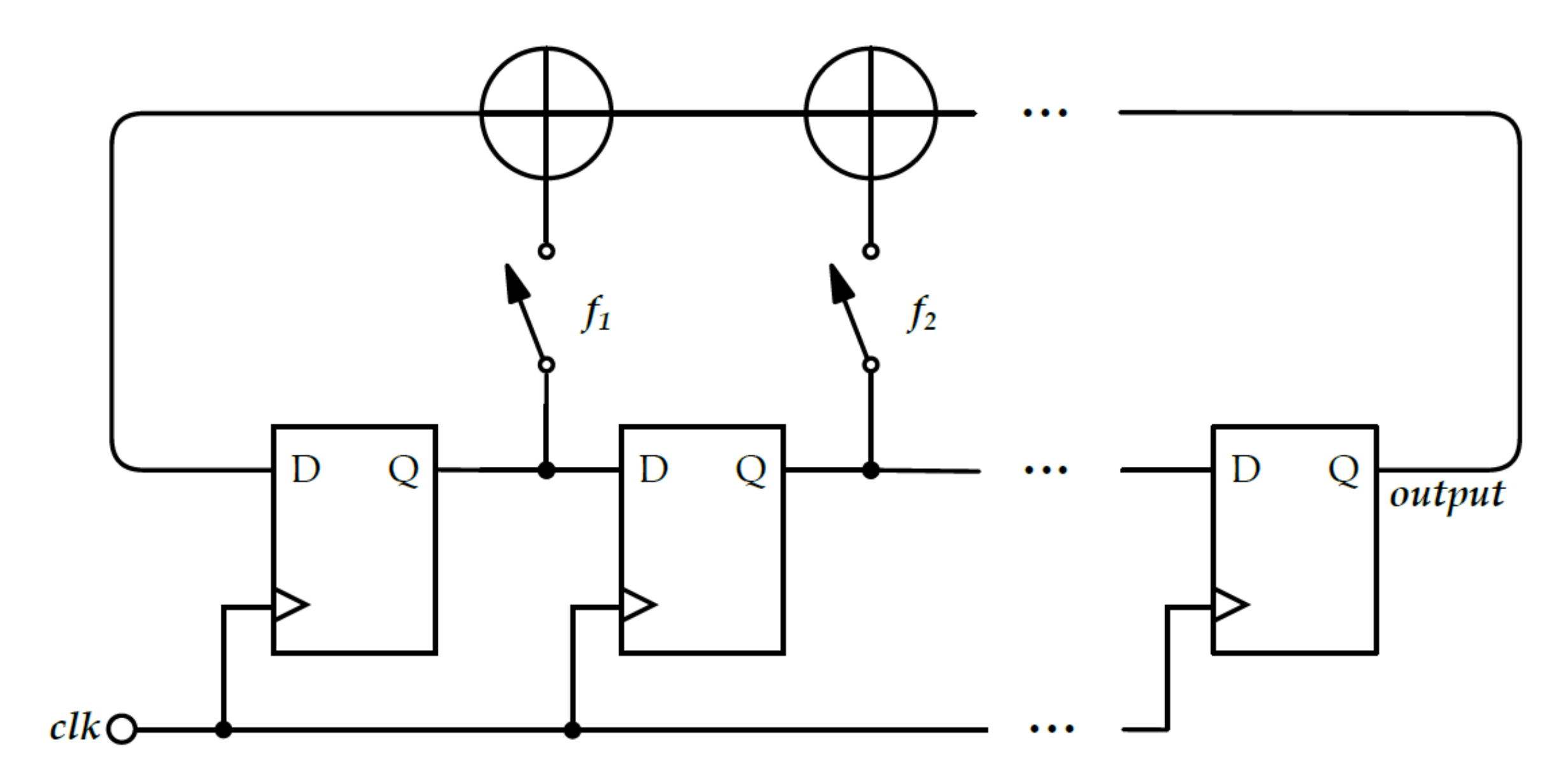
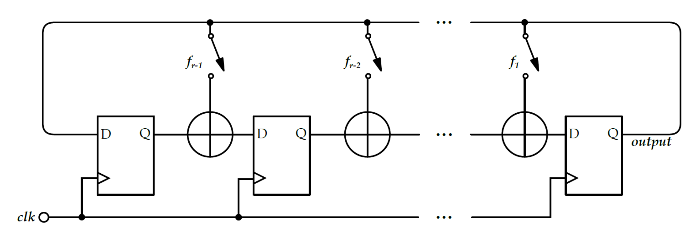
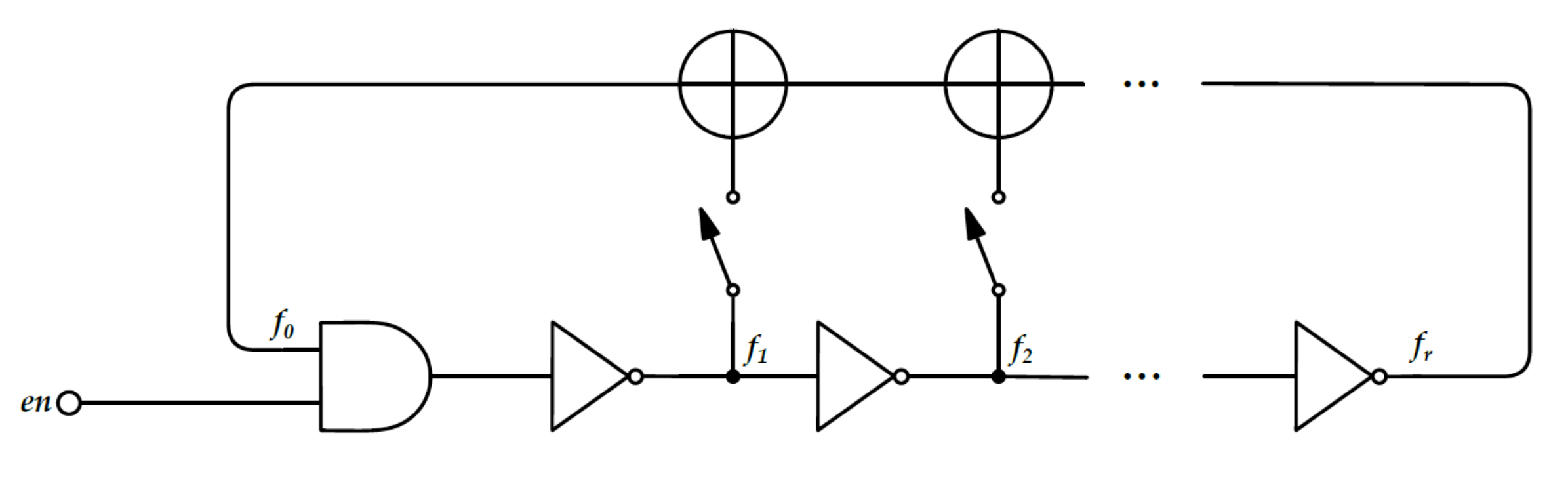
2.2.3. Fibonacci and Galois Ring Oscillators

Before presenting Fibonacci and Galois Ring Oscillators, it is worthwhile to introduce concepts about Linear Feedback Shift Registers, whose structures inspired these True-Random Bit Generators (TRBGs). A Linear Feedback Shift Register (LFSR) is a shift register with a feedback network, usually a XOR tree, which feeds the input with a linear function of the current internal state. The degree m of the LFSR equals the length of shift register itself. Two different architectures of LFSR, Fibonacci and Galois, are pictured in Figure 3 and Figure 4. In the former, the outputs of the D flip-flop (DFF), which are closed in retro-action by the switches, are XORed together and connected to the serial input of the shift register. The latter presents a different concept: if f r i is 0 (switch opened), DFFi feeds DFFi+1 as in a normal shift register operation; on the contrary, if f r i is 1 (switch closed), the output of DFFi is XORed with the serial output of the shift register to create the input for DFFi+1. In both cases, the feedback function is controlled by the switches f i , that are conventionally closed if f i = 1 or opened if f i = 0 . These values can be seen as coefficients of a polynomial: the characteristic polynomial of the LFSR.
P ( x ) = 1 + f 1 x + f 2 x 2 + + f m x m
Since the new state depends only on the previous one and the number of states is finite (they are, in fact, bounded by the length of the Shift Register), every LFSR outputs a periodic pattern.
It is possible to generate pseudo-random sequences with an LFSR that has a much bigger period than the length of the output sequence. Nevertheless, no entropy is ever generated inside an all-deterministic circuit like this one and it is simple to prove that LFSRs show neither prediction nor backtracking resistance. A change in these two architectures was introduced in [24], where two new TRNG architectures were presented: Fibonacci Ring Oscillators (FiROs) and Galois Ring Oscillators (GaROs).
FiRO is derived from its homonym LFSR architecture, substituting all D flip-flops with inverters, as shown in Figure 5. Since all synchronous elements are removed, the circuit is fully asynchronous and evolves in a stochastic fashion. Randomness is introduced by the dependency of the delay of the inverter from temperature and supply voltage: as these parameters vary, both for noise and environmental changes, the ring evolves with different output patterns, resulting in a chaotic and unpredictable signal. Additional randomness can be acquired during the sampling phase: the violation of setup and hold times can lead to metastability of the sampling unit. FiRO is made up by r inverter elements cascaded so that everyone (except the last one) creates the input for the next inverter. Feedback function is defined, as in LFSR, by the coefficients fi, which can be represented with the characteristic polynomial:
P ( x ) = i = 0 r f i x i w i t h f 0 = f r = 1
To ensure enough randomness, it is important to avoid fixed points, so that oscillation never stops. No fixed-points are present if these two conditions are satisfied1:
P ( x ) = ( x + 1 ) h ( x ) h ( 1 ) = 1
GaRO is derived from Galois LFSR structure, again substituting all D flip-flops with inverters, as shown in Figure 6. The same considerations made with FiRO on the stochastic evolution of this circuit hold. GaROs are made up by r inverters cascaded so that each inverter output is the input of a XOR gate which forms the input of the next inverter. The feedback function can be represented with the characteristic polynomial:
P ( x ) = i = 0 r f i x i w i t h f 0 = f r = 1
The conditions for GaROs not to have fixed points are the following:
P ( 1 ) = 0 r i s o d d
Both FiROs and GaROs feature an AND gate able to stop the oscillation and reduce power consumption when entropy is not required.

2.2.4. FiGaRO True Random Number Generator

As suggested in [24], the randomness, as well as robustness, can be further increased by XOR-ing the outputs of a Fibonacci Ring Oscillator and a Galois Ring Oscillator. The structure formed by XORing FiRO and GaRO is named as a FiGaRO structure. Figure 7 shows an example of a FiGaRO structure as specified in [24] composed of four FiRO and four GaRO connected using a XOR tree. The lengths of the two oscillators minus one should preferably be mutually prime to maximize the period of the corresponding pseudorandom sequence and to reduce coupling effect. Besides, it is suggested that the lengths differ only by one, where the even length corresponds to the Fibonacci ring oscillator.

3. True Random Number Generators Design and Evaluation on FPGA Technology

3.1. Methods for FPGA Technology-Based TRNGs Analysis

As addressed in previous sections, a TRNG exploits various noise sources to produce a random output. This characteristic implies that the testing functionality of these devices is not straightforward. Register Transfer Level (RTL) functional simulations are not suitable, since their incapability of resolving a combinational loop which is present in almost every state of the art TRNG. Post-layout simulations can do this, but metastability events, which are a fundamental part of the entropy harvesting process, lead to the propagation in the sampling chain of an undefined logic state (X). Analogue simulation tools provide functionalities for time-domain noise analysis and it is possible to find in literature articles where these are used for Application-Specific Integrated Circuit (ASIC) simulation of a TRNG [19]. Nevertheless, our main target for the implementation is the FPGA and no models are provided by vendors to test the dynamical behaviour of a noise dependant combinational loop. For these reasons, testing has been necessarily carried out in hardware. Our testing strategy focused on the direct extraction of a set of random values on the FPGA, which are then transmitted to an external computer for processing and evaluation.
In the test campaign reported in this section, we carried out a test on the already presented RNG architectures (TERO, Meta-RO, FIRO, GARO and FiGaRO). The objective of this test campaign is to find the best architecture for FPGA, where the figure of merit is the randomness of the outputs. Working on the FPGAs, we tried to test different placement techniques for the hardware, to find an architecture whose entropy was not affected by the placement of the hardware within the FPGA. The evaluation of distribution uniformity is carried out quantitatively at first examination. The selected RNG will then be tested with the NIST entropy assessment test suite to evaluate precisely its quality. Performances of some devices may be influenced by different placing and routing in the FPGA device. Where necessary, constraints have been created in the FPGA development tool to address these issues: employing Design Partition and LogicLock features the placing and routing of a single TRNG element mapped into a restricted number of Logic Array Blocks (LABs) have been saved, to be recallable multiple times and positioned in different cells controlled by the user. Such constraints can be easily ported in any FPGA development tool. By doing so, it has been possible to test different floor-plan configurations and extract more accurate results.

3.2. Candidate Solutions

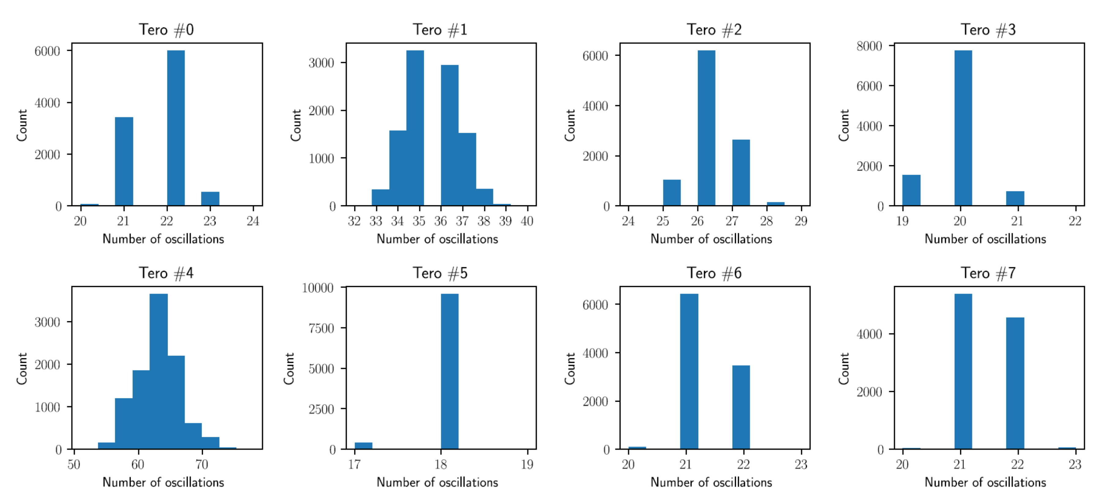
3.2.1. Transition Effect Ring Oscillator (TERO)

To test the TERO presented in Section 2.2.2 it is necessary to evaluate the number of oscillation the latch performs every time the ctrl signal toggles. To do so, a 10-bit asynchronous counter has been placed at the output of the device. Using a 10-bit counter instead of a single T Flip flop, not only we determine if the number of oscillations is odd or even: it is possible to check the exact number of oscillations. The expected outcome is to find a distribution of the number of oscillations similar to the ones showed in [25,26]. The actual output random variable is a binary variable which equals one if the amount of oscillation is an odd number or zero if it is an even number. Samples can be regarded as independent since TERO outputs a single bit for every restart, zeroing possible dependencies between successive samples. Instances, where numbers of oscillations are more spread, provide lower differences between ones and zeros, i.e., a higher entropy. We placed multiple TEROs on the FPGA with the same internal placing and routing, constrained into a single group of 10 Adaptive Logic Modules (ALMs). This saved element has been positioned multiple times, to test whether the observed behaviour depended or not from placing inside the FPGA device. From each TERO a sequence of 10,000 numbers of oscillations has been extracted and histograms of these values have been plotted. Figure 8 reports the number of oscillations occurred before having the output of the latch stable, in 8 different TERO elements. As shown, the histograms of the number of oscillations are very different from one element to another: some, like TERO 5, almost have a fixed number of oscillations, while others, like TERO 4, show a more complex plot. This variability was also found in [26]. The authors in [26,27] claim that routing and placing dependency is the main disadvantage of TERO. Techniques for overcoming this issue have been implemented in [27] on a Xilinx FPGA. However, the feasibility of such techniques strongly depend on the target platform and prevents the realization of a TRNG portable on different FPGAs.

3.2.2. Meta-Ring Oscillator (Meta-RO)

Meta-RO necessitates of a reliable delay line between the activation signal and the sampling clock. This delay can be obtained employing a PLL, which has been configured to produce the enable signal at the same frequency of the clock signal (100 MHz) with a phase shift of 1 ns. In our case, the PLL used is hardware primitive of the FPGA. Unlike TERO, in Meta-RO elements, the number of oscillations is not significant for the output statistic. Because of this, the testing proceeded in a slightly different way: eight instances of the same locked Meta-RO element have been positioned in different LABs and the parallel output value, interpreted as an 8-bit unsigned number (Sample Value, 0–255), has been evaluated, as showed in Figure 9. This test has been repeated multiples times, generating new bitstreams to understand dependencies from placing and routing. Every run has acquired 131,072 samples from eight parallel Meta-RO elements. Figure 10 shows histograms of the output values: even if the figures of merit of the oscillator itself can be considered satisfying (as shown in [28]), data are far from being uniformly distributed and the sawtooth shape highlights a predominance of zeros over ones, which reflects in low-quality output.

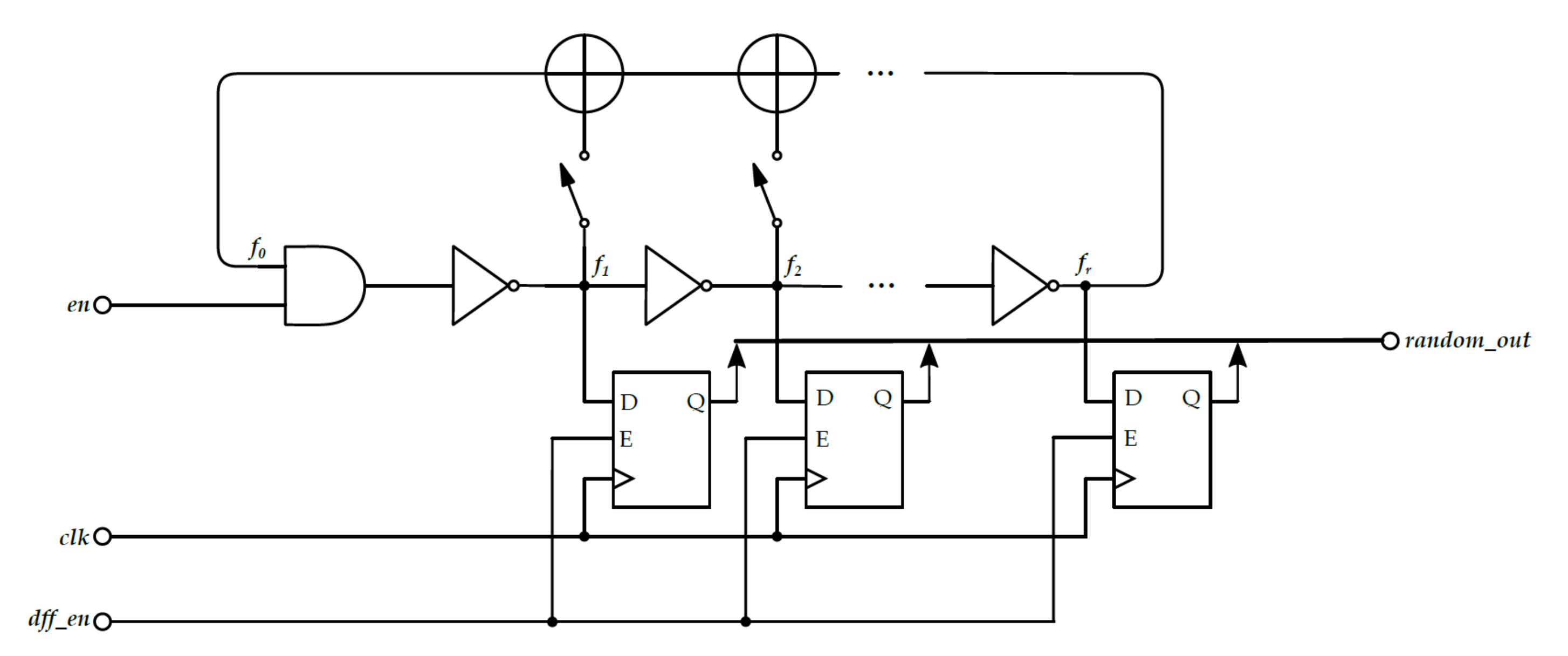
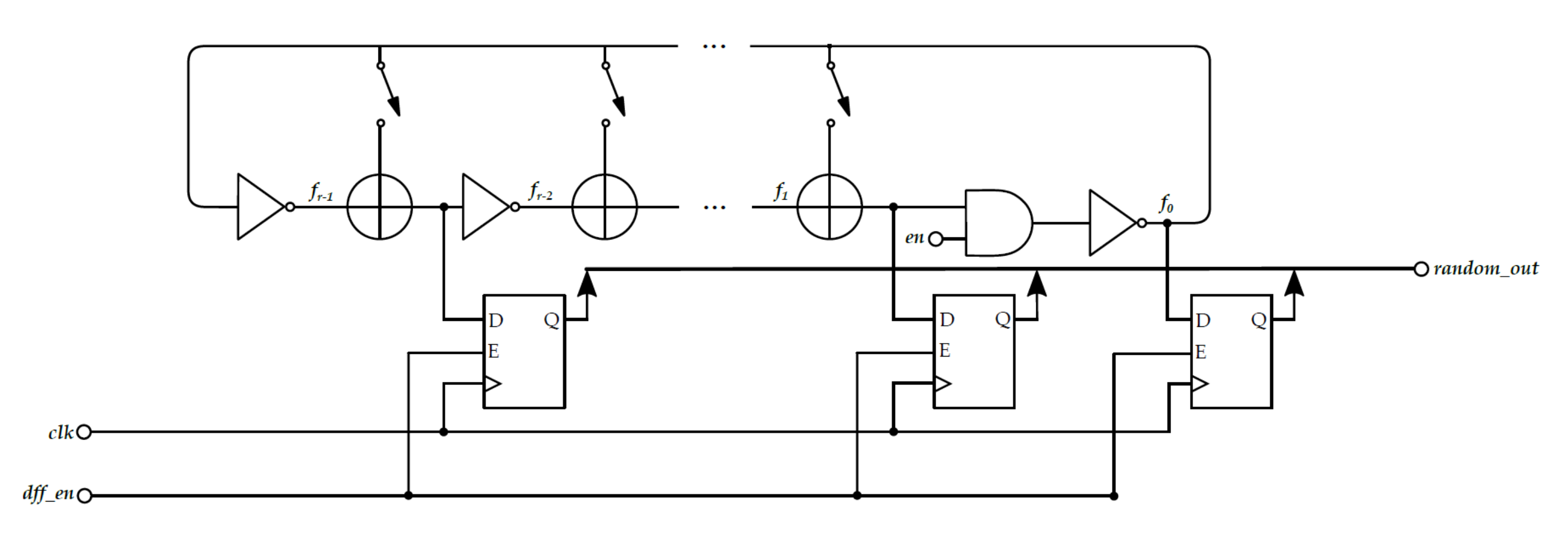
3.2.3. FiRO and GaRO

Several feedback polynomials can be selected in case of FiRO and GaRO. One of the possible choices is the one presented in [20] where all the FiRO and GaRO feedback networks are individually tested into Intel FPGA Cyclone V technology for oscillators lengths respectively equal to 10 and 11. Polynomials identified as best-in-class in [20] have been chosen for the implementation of the entropy source, and state sampling support has also been added, to sample not just the final inverter but all the internal states of the TRNG. Figure 11 and Figure 12 show the structure of FiRO GaRO, both with state sampling.
The first iteration of the test consisted of instantiating four FiRO and four GaRO with the feedback configurations reported below, and reading their 8-bit parallel output 131,072 times. Please note that F stands for FiRO and G for GaRO.
p 0 F ( x ) = 1 + x + x 2 + x 3 + x 5 + x 6 + x 7 + x 8 + x 9 + x 10
p 1 F ( x ) = 1 + x + x 2 + x 3 + x 4 + x 6 + x 7 + x 10
p 2 F ( x ) = 1 + x + x 2 + x 3 + x 4 + x 5 + x 6 + x 10
p 3 F ( x ) = 1 + x + x 2 + x 3 + x 4 + x 5 + x 6 + x 7 + x 9 + x 10
p 0 G ( x ) = 1 + x 2 + x 3 + x 5 + x 6 + x 7 + x 9 + x 11
p 1 G ( x ) = 1 + x 2 + x 3 + x 5 + x 6 + x 7 + x 8 + x 11
p 2 G ( x ) = 1 + x 2 + x 3 + x 4 + x 5 + x 7 + x 9 + x 11
p 3 G ( x ) = 1 + x 2 + x 3 + x 4 + x 5 + x 6 + x 9 + x 11
No particular constraints are given for the sampling frequency and the placing and routing. Comparing the acquisition run depicted in Table 2 with the ones acquired for Meta-RO, it is evident the reduced bias confirmed by the ones and zeros count.

3.2.4. FiGaRO

The structure reported in Figure 7 has been used to form a single output bit, and it has been replicated eight times to produce an 8-bit parallel output. From this structure higher entropy is expected and this is confirmed by experimental results: the same number of acquired samples, led to a more uniform distribution, as showed in Figure 13. As shown in Table 3, there is a very good balance between the number of ones and zeros and biases appear, to the first analysis, to be random and physiologic due to the limited dataset we are considering.

3.3. FiGaRO RNG Design
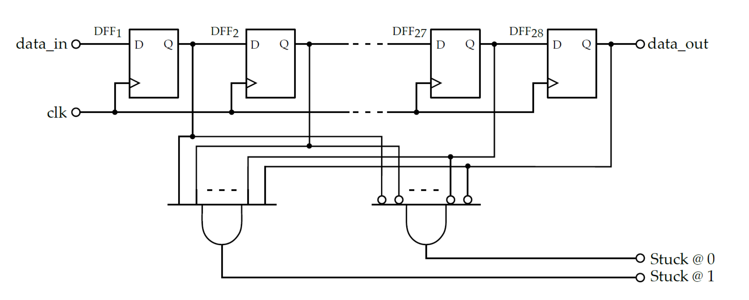
The FiGaRO architecture, already proved to overcome classical ring oscillators [21], demonstrated to be the best among all the other presented oscillators in terms of entropy for an FPGA device. Once selected the FiGaRO as an entropy source, we moved on the design of the complete random number generator, which include also control sections and health test circuits. Such a system has been then tested against the NIST test suite to demonstrate its compliance with the relevant standard. In this chapter, we will illustrate how the building blocks of RNG were designed in SystemVerilog and implemented in FPGA technology. The RNG design must comprehend both the entropy harvesting device (i.e., the TRNG), and health tests circuits.

3.3.1. Health Tests

In every entropy source, the statistical quality of the output must be continuously tested to check if significant deviations are taking place, due to changed environmental conditions, electric fields or side-channel attacks. To avoid situations where the entropy is too low, it is mandatory to quickly diagnose a possible fault, inhibiting the output until the quality is restored. As recommended by NIST in [29], two on-line health tests are needed for an entropy source: the repetition count test and the adaptive proportion test, which are described in the following.
The repetition count test triggers an alarm if the same output value is maintained too many times in a row. To perform this test, a rate of false probability α must be chosen: the higher is this rate, the lower number of repetitions will trigger the alarm. Once chosen α , the number of repetitions which trigger an alarm is given by this formula:
n = 1 + l o g 2 ( α ) H
A hardware that implements this test for binary sources is proposed hereafter: a shift register continuously acquires the outputs of the entropy source and additional logic checks if shift register’s parallel output is made up by only ones or only zeros. This implementation is depicted in Figure 14.
The adaptive proportion test is built to check if the frequency of occurrence of every possible output value falls within a certain confidence interval. If an output occurs too much frequently, it means that the statistical quality of the randomness source is lowered and an alarm should be triggered. For binary outputs, the test must be performed on a window of 1024 samples. The number of ones must be counted and compared to two different values: if the count of ones exceeds a cut-off value C or is lower than ( 1024 C ) an alarm should be raised. Cut-off values are indicated by NIST as a function of the bitstream entropy. Again, a hardware implementation, depicted in Figure 15 of this test is proposed. A shift register of 1024 bit maintains the memory of the last output values and whenever a new value comes in, its value is summed into an accumulator register, while the last value is subtracted. By doing so, the accumulator always maintains the count of the number of ones inside the observation window and two comparators can check if the frequency lies inside the upper and lower thresholds.

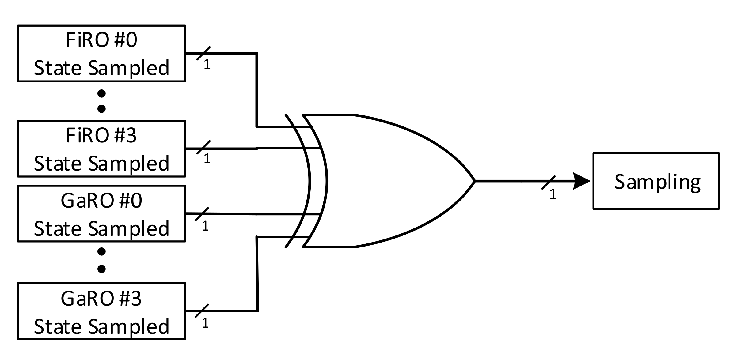
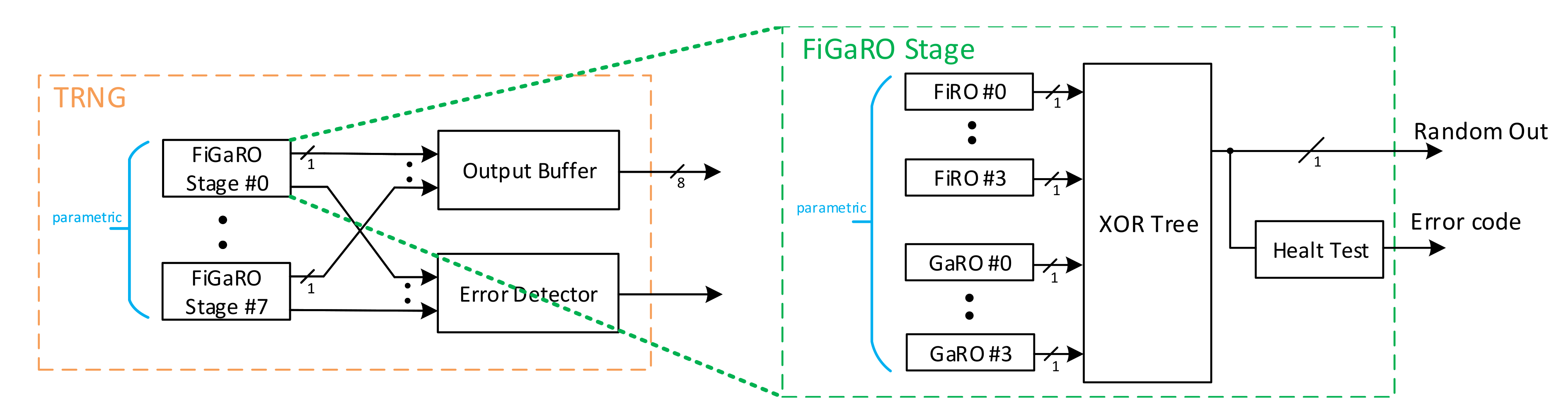
3.3.2. Overall RNG Architecture

Figure 16 shows the architecture of the proposed RNG. FiROs and GaROs, configured as a FiGaRO, were selected as an entropy source. Our contribution to it is the inclusion of the health test and the combination of a parametric number of stages, to increase the throughput. Such architecture showed to be the most suitable for FPGA implementation due to its independence from placing and routing into FPGA. The final design has been parametrized to be customizable in several stages (i.e., the number of parallel TRNG): one, two, four and eight elements with 1-bit output can be placed in parallel. Every stage is referred to as a FiGaRO Stage, as showed in Figure 16. Please note that the number of FiRO and GaRO placed in the same FiGaRO contributes on improving entropy and reliability: indeed, if one or more oscillator gets stuck you can still have a working TRNG since the single oscillators are XORed. On the other hand, the number of FiGaRO stages placed in parallel has the only effect to increase the throughput, paying linearly in resource consumption; entropy is not affected by this parameter. Every stage has the same structure: multiple FiRO and GaRO elements can be XORed together to form a high entropy output, with the feedback polynomial reported in Equations (9)–(16). Choosing different feedback networks, the correlation between FiROs and GaROs within a FiGaRO stage is minimized. This operation also ensures a higher degree of reliability of the Entropy Source, since various contributions sum up together masking possible momentarily failures of some oscillators. Besides, the number of FiRO and GaRO XORed in every stage has been parametrized to choose between one FiRO and one GaRO (with polynomials Equations (9) and (13)), two FiRO and two GaRO (with polynomials Equations (9), (10), (13) and (14)), four FiRO and four GaRO. Each FiGaRO Stage is accompanied by its health tests, implemented as reported in Section 3.3.1. The error detector circuits signal to the user failures of the health tests of each FiGaRO stage, so that the user can take countermeasures.

4. Implementation Results

The preliminary analysis presented in Section 3.2 was conducted qualitatively, focusing primarily on evaluating the empirical results obtained from the different TRNG architectures. Nevertheless, there was the necessity to validate the selected architecture using approved tests which could output an affordable estimation of the entropy of this device.

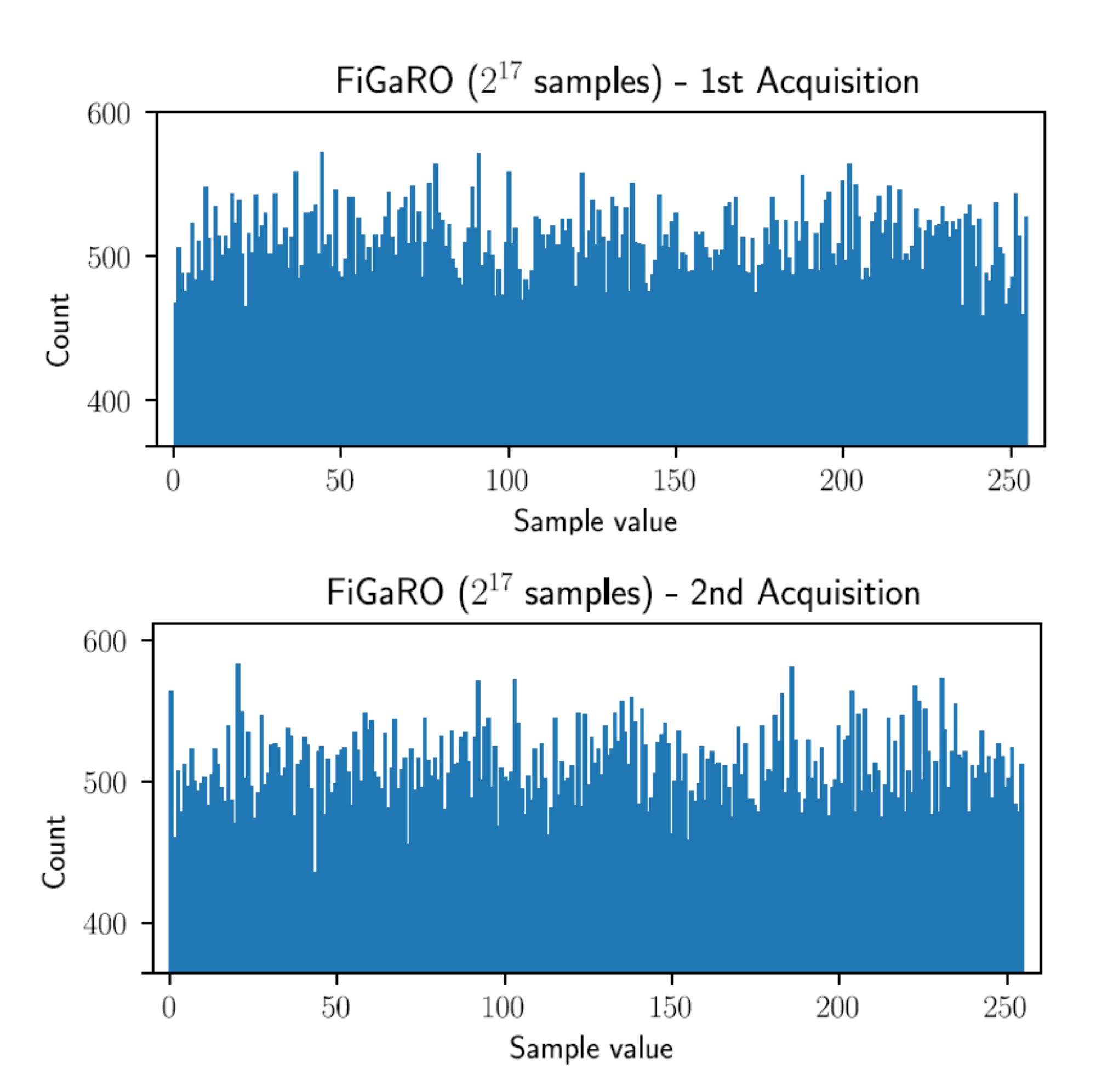
4.1. FiGaRO RNG Entropy Measurement

To assess the quality of the output sequence generated by the Entropy Source, it was necessary to evaluate the min-entropy per bit of the generated sequence using specific tests. These tests are proposed and described in [29], while a test suite, based on these specifications, was provided by NIST itself and is openly available in [30]. Two things were investigated during these tests:
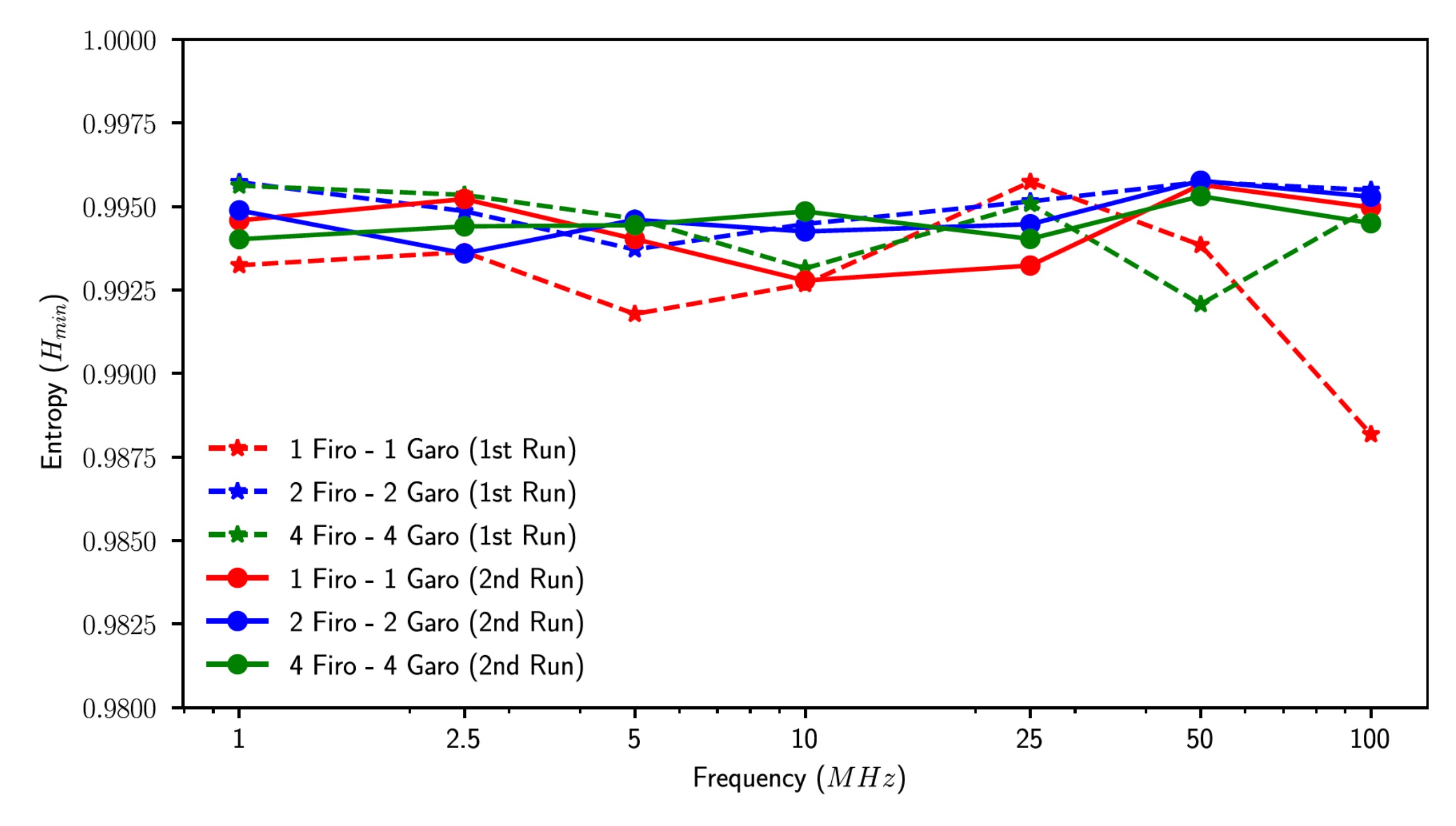
  • The first one regards how the output quality depended on the number of elements XORed together inside each FiGaRO stage. Ideally, the more elements were used, the more the output quality was high but this depended on an assumption of device independence, which had to be verified.
  • The second one regards how the output quality depended on the sampling frequency. Until this point sampling took place at 1 MHz but deriving a plot of entropy as a function of frequency may have allowed us to make a trade-off between entropy source throughput and output quality.
Before testing, data collection had to be carried out in a specific way. In particular, for every test was provided a sequence of at least 1 million consecutive samples, called S:
S = [ s 0 s 1 s 999999 ]
and a 1000 × 1000 restart matrix, called from now on R, constructed restarting the entropy source 1000 times and populating every row with 1000 consecutive samples:
R = S 0 0 S 1 0 S 2 0 S 999 0 S 0 1 S 1 1 S 2 1 S 999 1 S 0 999 S 1 999 S 2 999 S 999 999
From R, two sequences were constructed: the row dataset, made up by the concatenation of all the rows of R:
R r o w = [ s 0 0 S 999 0 s 0 1 S 999 1 S 0 999 S 999 999 ]
The columns dataset, composed by the concatenation of all the rows of R T :
R c o l = [ s 0 0 S 999 0 s 0 0 S 1 999 S 999 0 S 999 999 ]
Once the dataset was constructed, it could be provided to the NIST statistical test suite described in [29], to check the Independent and Identically Distributed (IID) assumption: if the IID assumption was verified, the entropy assessment was greatly simplified, since only one test (the most common value entropy estimate) needed to run.
Seven sampling frequencies were chosen for the frequency sweep:
f = [ 1 , 2.5 , 5 , 10 , 25 , 50 , 100 ] M H z
Then all three configurations of a FiGaRO Stage, which provided the sequence under test, were tested:
  • 1 FiRO and 1 GaRO XORed together
  • 2 FiRO and 2 GaRO XORed together
  • 4 FiRO and 4 GaRO XORed together
This resulted in the acquisition of 21 different cases for each test run. For each case, it was necessary to acquire 1,048,576 sequential samples and of a 1000 × 1000 restart matrix. An IID claim was made for all the sequential sequences and NIST tests (permutation and chi-square tests) confirmed this claim. The entropy awarded at the end of testing was:
H m i n = m i n ( H I , H R , H C )
where H I is the initial entropy estimate of the sequential dataset and H R and H C are awarded to the restart dataset. Figure 17 shows H m i n values obtained in two runs of tests. All configurations showed high quality quite independently from the sampling frequency, with all entropies settling around 0.995. Since sometimes these types of results are presented with Shannon metric of Entropy, a conversion from H m i n to H S is provided below.
H m i n 0.995 max i ( p i ) = 2 H m i n = 0.50173587425
H s = 2 H m i n log 2 ( 2 H m i n ) ( 1 2 H m i n ) log 2 ( 1 2 H m i n ) = 0.9999913
Please note that just the 1FiRO-1GaRO configuration had a slightly lower entropy level. 2FiRO-2GaRO and 4FiRO-4GaRO configuration were comparable in terms of entropy.

4.2. Synthesis and Implementation Results

In Table 4 we present the implementation results obtained on a Stratix IV FPGA. The synthesis operating frequency was fixed to 100 MHz, therefore each FiGaRO stage contributed with 100 Mbps to the throughput; thus, we achieved a throughput of 400 Mbps for a four stage oscillator and 800 Mbps for an eight stage oscillator. The results are shown varying the number of FiGaRO stages and the configuration. The obtained numbers showed, as expected, that the resources usage grew linearly with both these parameters.
Considering also the results achieved in terms of entropy, we observed the following:
  • 1FiRO-1GaRO Configuration was the one with smaller area footprint but also the worst entropy;
  • 2FiRO-2GaRO and 4FiRO 4GaRO were comparable in terms of entropy;
  • System robustness to possible stuck in the oscillation grew linearly with the number of FiRO and GaRO composing a FiGaRO stage;
  • Resources usage grew linearly with the number of FiRO and GaRO composing a FiGaRO stage;
  • The throughput of the system grew linearly with the number of FiGaRO stages in parallel;
  • Resources usage grew linearly with the number of FiGaRO stages in parallel;
Table 5 shows a comparison between our work and other TRNGs implemented on FPGA platforms. Please note that we did not implement the reported design but we relied on the results presented in the cited works. For the same reason and for conciseness, we do not report the architectural details of the design here; they can be accessed by consulting the cited works. Unfortunately the available works relied on different FPGA technology nodes: this made unfair the comparison in terms of bit rate, as newer technologies obviously are able to reach higher clock speeds. However, the rest of the metrics were not directly affected by the technology node. Moreover, most of the proposed solutions (e.g., the Self-Timed Rings (STRs) based one) were not limited by the technology but rather than entropy harvesting method: the clock frequency was limited well under the maximum available values to preserve the randomness quality. The overall comparison gave however an indication on the achievable throughput of random numbers, together with the randomness quality (entropy).
In [27] the authors demonstrate that the TERO is highly dependent on the origin of placement; therefore, they introduce a particular TERO (TC-TERO) which overcome this issue, at the price of employing FPGA dependent primitives, loosing therefore the technology independence. The authors in [34] proposed an implementation based on Coherent Sampling (CS) phenomenon using Self-Timed Rings (STRs) instead of the commonly employed Ring Oscillators (ROs). The authors demonstrated the portability of the design and they achieved an extremely compact design, but the bit-rate remained limited due to the low sampling frequency. In fact, the design has been synthesized at 1 MHz on a Xilinx Virtex 6 FPGA, and the authors declare that higher sampling frequencies might degrade the randomness quality. On the contrary, as shown in Figure 17, in our proposed solution entropy is stable with frequency variations. The design proposed in [31] is based on the Edge Sampling (ES) technique and achieves the lowest resource consumption. The throughput remains limited to 1.15 Mbps and 1.07 Mbps respectively on Xilinx Spartan-6 FPGA and Intel Cyclone V FPGAs, with a Shannon entropy of 0.997; according to the authors, this entropy cannot be achieved for higher frequency without dedicated post-processing circuits. The works in [32,33] employed RO as entropy sources. In particular, the authors in [33] incorporated Programmable Delay Lines (PDLs) to generate a large variety of the oscillations and to introduce jitter, achieving high entropy. Even if the achieved entropy is remarkable, the resource utilization is not negligible and moreover the result is highly influenced by the operating frequency, which is a limitation not present in our proposed TRNG. In [35], authors presents another STRs-based implementation. The Bit Rate to resource ratio is much greater than the one presented in [34]; however, it is difficult to further compare them due to the lack of measured entropy. Finally, in [36], authors propose a very competing solution in terms of entropy, complexity and resource usage. The disadvantage here comes from the fact that the sole employment of GaRO makes the oscillator more susceptible to faults respect to the FiGaRO approach [24]. Our work showed a very high throughput with a resource consumption in line with other works, and a high level of entropy per bit. Additionally, our implementation can therefore be adapted to the user needs easily, paying a resource utilization fee linearly with the required level of robustness and the required bandwidth. For what concerns entropy, we recommend to use the 1FiRO-1GaRO configuration only for a resource optimized scenario, otherwise since the required hardware is still limited, it is possible to achieve higher entropy with the other two configurations.

4.3. NIST Statistical Test Suite

The quality of the designed entropy source was assessed by the commonly used NIST 800.22 statistical test suite [37]. It consisted of 15 type of tests which were performed to assess the performance of TRNGs. Such tests were carried out for the proposed FiRO-GaRO configurations (i.e., 1FiRO-1GaRO, 2FiRO-2GaRO and 4FiRO-4GaRO) at 50 MHz and 100 MHz. A total of 320 sequences with a length of 1 Gbit were collected and tested for each configuration. The parameters of each test were set following the NIST recommendations [37]. In Table 6 the results obtained with a 50 MHz sampling rate are shown, while in Table 7 we present the results with a 100 MHz sampling rate. Both tests refer to the implementation of the aforementioned Stratix IV FPGA. The statistical p-value should be greater than 0.01 if the test item was passed and the proportion of passed sequences to total sequences should be larger than 0.980. All tests were considered passed as they scored above the threshold. The entropy level demonstrated itself to be similar in all the cases, with the 1FiRO-1GaRO configuration achieving slightly lower entropy levels.

5. Conclusions

This work presented an analysis of existing TRNGs and a methodology to assess which one can be claimed to be the best option in terms of entropy and robustness to placing mismatch. We illustrated the design flow of such TRNG for FPGA, from architecture definition to implementation, testing and performance evaluation. The testing phase focused on the entropy source, evaluating different state-of-the-art TRNG circuits in FPGA technology and testing their output quality. We proposed a design of a very robust entropy source, employing multiple FiROs and GaROs, which showed the best performances between all tested elements in terms of entropy on FPGA devices. The architecture has been validated with NIST Entropy Assessment Suite on FPGA platform, with an estimated Min-Entropy approximately equal to 0.995 bit per output bit, in line with state-of-the-art literature results. Such a value proved to oscillate negligibly for different sampling frequencies and configurations. The entropy source configuration is selectable at synthesis time, accordingly to user necessities concerning latency and area, using specific parameters which control the number of stages as well as the number of oscillators in every stage. We illustrate how the hardware parameters ( number of stages and composition of each stage) varies throughput and robustness, without affecting significantly the entropy. In particular, we achieved an overall throughput of 400 Mbps for a four stage FiGaRO oscillator, 100 Mbps per stage, which is in line with the state of the art concerning entropy and complexity and it is an advancement with the throughput. The absence of particular constraints on placing and routing guarantees a wide range of technology targets or different operating conditions.

Author Contributions

Conceptualization and methodology, P.N., S.D.M., L.B. and L.C.; Validation, J.B.; Project administration ad founding acquisition, S.S. and L.F. All authors have read and agreed to the published version of the manuscript.

Funding

The early stage of this work has been partially funded by MIUR, in the Crosslab project under the Dipartimento di excellence programme and by the European Processor Initiative (EPI) project, under grant agreement N. 826646.

Conflicts of Interest

The authors declare no conflict of interest.

References

  1. Rostami, M.; Koushanfar, F.; Karri, R. A Primer on Hardware Security: Models, Methods, and Metrics. Proc. IEEE 2014, 102, 1283–1295. [Google Scholar] [CrossRef]
  2. El Mrabet, Z.; Kaabouch, N.; El Ghazi, H.; El Ghazi, H. Cyber-security in smart grid: Survey and challenges. Comput. Electr. Eng. 2018, 67, 469–482. [Google Scholar] [CrossRef] [Green Version]
  3. Rivest, R.L.; Shamir, A.; Adleman, L. A Method for Obtaining Digital Signatures and Public-Key Cryptosystems. Commun. ACM 1978, 21, 120–126. [Google Scholar] [CrossRef]
  4. Badra, M.; Guillet, T.; Serhrouchni, A. Random values, nonce and challenges: Semantic meaning versus opaque and strings of data. In Proceedings of the 2009 IEEE 70th Vehicular Technology Conference Fall, Anchorage, AK, USA, 20–23 September 2009; pp. 1–5. [Google Scholar]
  5. Jan Pelzl, C.P. Understanding Cryptography; Springer: Berlin/Heidelberg, Germany, 2011. [Google Scholar]
  6. Hong, S.L.; Liu, C. Sensor-based random number generator seeding. IEEE Access 2015, 3, 562–568. [Google Scholar] [CrossRef]
  7. Baldanzi, L.; Crocetti, L.; Falaschi, F.; Bertolucci, M.; Belli, J.; Fanucci, L.; Saponara, S. Cryptographically secure pseudo-random number generator IP-core based on SHA2 algorithm. Sensors 2020, 20, 1869. [Google Scholar] [CrossRef] [PubMed] [Green Version]
  8. Simion, E. Entropy and Randomness: From Analogic to Quantum World. IEEE Access 2020, 8, 74553–74561. [Google Scholar] [CrossRef]
  9. Gong, L.; Zhang, J.; Liu, H.; Sang, L.; Wang, Y. True random number generators using electrical noise. IEEE Access 2019, 7, 125796–125805. [Google Scholar] [CrossRef]
  10. Tehranipoor, F.; Wortman, P.; Karimian, N.; Yan, W.; Chandy, J.A. DVFT: A Lightweight Solution for Power-Supply Noise-Based TRNG Using Dynamic Voltage Feedback Tuning System. IEEE Trans. Very Large Scale Integr. Syst. 2018, 26, 1084–1097. [Google Scholar] [CrossRef]
  11. Rahman, M.T.; Xiao, K.; Forte, D.; Zhang, X.; Shi, J.; Tehranipoor, M. TI-TRNG: Technology independent true random number generator. In Proceedings of the 2014 51st ACM/EDAC/IEEE Design Automation Conference (DAC), San Francisco, CA, USA, 1–5 June 2014; pp. 1–6. [Google Scholar] [CrossRef]
  12. Tokunaga, C.; Blaauw, D.; Mudge, T. True Random Number Generator with a Metastability-Based Quality Control. IEEE J. Solid-State Circuits 2008, 43, 78–85. [Google Scholar] [CrossRef]
  13. Wieczorek, P.Z.; Gołofit, K. Dual-Metastability Time-Competitive True Random Number Generator. IEEE Trans. Circuits Syst. I Regul. Pap. 2014, 61, 134–145. [Google Scholar] [CrossRef]
  14. Sivaraman, R.; Rajagopalan, S.; Sridevi, A.; Rayappan, J.B.B.; Annamalai, M.P.V.; Rengarajan, A. Metastability-Induced TRNG Architecture on FPGA. Iran. J. Sci. Technol. Trans. Electr. Eng. 2020, 44, 47–57. [Google Scholar] [CrossRef]
  15. Amaki, T.; Hashimoto, M.; Onoye, T. An oscillator-based true random number generator with jitter amplifier. In Proceedings of the 2011 IEEE International Symposium of Circuits and Systems (ISCAS), Rio de Janeiro, Brazil, 15–18 May 2011; pp. 725–728. [Google Scholar] [CrossRef]
  16. Valtchanov, B.; Aubert, A.; Bernard, F.; Fischer, V. Modeling and observing the jitter in ring oscillators implemented in FPGAs. In Proceedings of the 2008 11th IEEE Workshop on Design and Diagnostics of Electronic Circuits and Systems, Bratislava, Slovakia, 16–18 April 2008; pp. 1–6. [Google Scholar] [CrossRef]
  17. Zacharias, A.; Gisha, C.G.; Jose, B.A. Chaotic Ring Oscillator Based True Random Number Generator Implementations in FPGA. In Proceedings of the 2020 24th International Symposium on VLSI Design and Test (VDAT), Bhubaneswar, India, 23–25 July 2020; pp. 1–6. [Google Scholar] [CrossRef]
  18. Varchola, M.; Drutarovsky, M. New high entropy element for FPGA based true random number generators. In International Workshop on Cryptographic Hardware and Embedded Systems; Springer: Berlin/Heidelberg, Germany, 2010; pp. 351–365. [Google Scholar]
  19. Vasyltsov, I.; Hambardzumyan, E.; Kim, Y.S.; Karpinskyy, B. Fast digital TRNG based on metastable ring oscillator. In International Workshop on Cryptographic Hardware and Embedded Systems; Springer: Berlin/Heidelberg, Germany, 2008; pp. 164–180. [Google Scholar]
  20. Schramm, M.; Dojen, R.; Heigl, M. Experimental assessment of FIRO-and GARO-based noise sources for digital TRNG designs on FPGAs. In Proceedings of the 2017 IEEE International Conference on Applied Electronics (AE), Pilsen, Czech Republic, 5–6 September 2017; pp. 1–6. [Google Scholar]
  21. Demir, K.; Ergün, S. A Comparative Study on Fibonacci-Galois Ring Oscillators for Random Number Generation. In Proceedings of the 2020 IEEE 63rd International Midwest Symposium on Circuits and Systems (MWSCAS), Springfield, IL, USA, 9–12 August 2020; pp. 631–634. [Google Scholar]
  22. Acar, B.; Ergün, S. A Robust Digital Random Number Generator Based on Transient Effect of Ring Oscillator. In Proceedings of the 2020 IEEE 11th Latin American Symposium on Circuits Systems (LASCAS), San José, Costa Rica, 25–28 February 2020; pp. 1–4. [Google Scholar] [CrossRef]
  23. Reyneri, L.M.; Del Corso, D.; Sacco, B. Oscillatory metastability in homogeneous and inhomogeneous flip-flops. IEEE J. Solid State Circuits 1990, 25, 254–264. [Google Scholar] [CrossRef]
  24. Golic, J.D. New methods for digital generation and postprocessing of random data. IEEE Trans. Comput. 2006, 55, 1217–1229. [Google Scholar] [CrossRef]
  25. Haddad, P.; Fischer, V.; Bernard, F.; Nicolai, J. A physical approach for stochastic modeling of TERO-based TRNG. In International Workshop on Cryptographic Hardware and Embedded Systems; Springer: Berlin/Heidelberg, Germany, 2015; pp. 357–372. [Google Scholar]
  26. Li, T.; Wu, L.; Zhang, X.; Wu, X.; Zhou, J.; Wang, X. A novel transition effect ring oscillator based true random number generator for a security SoC. In Proceedings of the 2017 IEEE International Conference on Electron Devices and Solid-State Circuits (EDSSC), Hsinchu, Taiwan, 18–20 October 2017; pp. 1–2. [Google Scholar]
  27. Fujieda, N. On the Feasibility of TERO-Based True Random Number Generator on Xilinx FPGAs. In Proceedings of the 2020 30th International Conference on Field-Programmable Logic and Applications (FPL), Gothenburg, Sweden, 31 August–4 September 2020; pp. 103–108. [Google Scholar]
  28. Stanchieri, G.D.P.; De Marcellis, A.; Palange, E.; Faccio, M. A true random number generator architecture based on a reduced number of FPGA primitives. AEU Int. J. Electron. Commun. 2019, 105, 15–23. [Google Scholar] [CrossRef]
  29. Turan, M.S.; Barker, E.; Kelsey, J.; McKay, K.A.; Baish, M.L.; Boyle, M. Recommendation for the Entropy Sources Used for Random Bit Generation; NIST DRAFT Special Publication 800-90B; NIST: Gaithersburg, MD, USA, 2018. [Google Scholar]
  30. Turan, M.S.; Barker, E.; Kelsey, J.; McKay, K.A.; Baish, M.L.; Boyle, M. SP800-90B Entropy Assessment; NIST: Gaithersburg, MD, USA, 2018. [Google Scholar] [CrossRef]
  31. Yang, B.; Mentens, N. ES-TRNG: A high-throughput, low-area true random number generator based on edge sampling. IACR Trans. Cryptogr. Hardw. Embed. Syst. 2018, 2018, 267–292. [Google Scholar] [CrossRef]
  32. Sunar, B.; Martin, W.J.; Stinson, D.R. A provably secure true random number generator with built-in tolerance to active attacks. IEEE Trans. Comput. 2006, 56, 109–119. [Google Scholar] [CrossRef]
  33. Anandakumar, N.N.; Sanadhya, S.K.; Hashmi, M.S. FPGA-based true random number generation using programmable delays in oscillator-rings. IEEE Trans. Circuits Syst. II Express Briefs 2019, 67, 570–574. [Google Scholar] [CrossRef]
  34. Martin, H.; Peris-Lopez, P.; Tapiador, J.E.; San Millan, E. A new TRNG based on coherent sampling with self-timed rings. IEEE Trans. Ind. Inform. 2015, 12, 91–100. [Google Scholar] [CrossRef] [Green Version]
  35. Wang, X.; Liang, H.; Wang, Y.; Yao, L.; Guo, Y.; Yi, M.; Huang, Z.; Qi, H.; Lu, Y. High-Throughput Portable True Random Number Generator Based on Jitter-Latch Structure. IEEE Trans. Circuits Syst. I Regul. Pap. 2021, 68, 741–750. [Google Scholar] [CrossRef]
  36. Lin, J.; Wang, Y.; Zhao, Z.; Hui, C.; Song, Z. A New Method of True Random Number Generation based on Galois Ring Oscillator with Event Sampling Architecture in FPGA. In Proceedings of the 2020 IEEE International Instrumentation and Measurement Technology Conference (I2MTC), Dubrovnik, Croatia, 25–29 May 2020; pp. 1–6. [Google Scholar] [CrossRef]
  37. Bassham, L.; Rukhin, A.; Soto, J.; Nechvatal, J.; Smid, M.; Leigh, S.; Levenson, M.; Vangel, M.; Heckert, N.; Banks, D. A Statistical Test Suite for Random and Pseudorandom Number Generators for Cryptographic Applications. NIST Special Publication 800-22 (revised on 15 May 2002); 2010. Available online: https://tsapps.nist.gov/publication/get_pdf.cfm?pub_id=906762 (accessed on 7 April 2021).
Figure 1. Transition-Effect Ring Oscillator.
Applsci 11 03330 g001
Figure 2. Metastable Ring Oscillator.
Applsci 11 03330 g002
Figure 3. Fibonacci Linear Feedback Shift Registers.
Applsci 11 03330 g003
Figure 4. Galois Linear Feedback Shift Register.
Applsci 11 03330 g004
Figure 5. Fibonacci Ring Oscillator with enable port.
Applsci 11 03330 g005
Figure 6. Galois ring oscillator with enable port.
Applsci 11 03330 g006
Figure 7. Fibonacci-Galois Ring Oscillator (FiGaRO) four elements architecture.
Applsci 11 03330 g007
Figure 8. Number of oscillations histogram for 10 5 trigger events for Transition Effect Ring Oscillator (TERO) True-Random Number Generator (TRNG).
Applsci 11 03330 g008
Figure 9. Sampling strategy for Meta-RO assessment.
Applsci 11 03330 g009
Figure 10. Output values histograms for eight parallel Meta-RO elements.
Applsci 11 03330 g010
Figure 11. Fibonacci Ring Oscillator with state sampling. The output bus is XORed together to form a 1-bit output in the higher level.
Applsci 11 03330 g011
Figure 12. Galois Ring Oscillator with state sampling. The output bus is XORed together to form a 1-bit output in the higher level.
Applsci 11 03330 g012
Figure 13. Histograms of the first run and of the second run of acquisitions for the FiGaRO TRNG.
Applsci 11 03330 g013
Figure 14. Hardware implementation of the repetition count test for a binary random source.
Applsci 11 03330 g014
Figure 15. Hardware implementation of the adaptive proportion test for a binary random source.
Applsci 11 03330 g015
Figure 16. Overall architecture of the implemented FiGaRO Random Number Generator (RNG).
Applsci 11 03330 g016
Figure 17. Entropy assessment results (two different runs of acquisition).
Applsci 11 03330 g017
Table 1. Digital True-Random Number Generators (TRNGs) in literature.
Ref.ArchitecturePhysical PhenomenaPreliminary
Generating EntropyObservation
[18]Transition Effect Ring Oscillator (TERO)Latches oscillatory metastabilitySmall bandwidth, large dependence on placing
[19]Metastable Ring Oscillators (Meta-RO)Analogue metastability of inverter gatesPLL required, dependence on placing
[20]Fibonacci Ring Oscillator (FiRO)Jitter and MetastabilityGood independence from placing
[20]Galois Ring Oscillator (GaRO)Jitter and MetastabilityGood independence from placing
[21]Fibonacci-Galois Ring Oscillator (FiGaRO)Jitter and MetastabilityIndependence from placing, higher entropy and robustness respect to single Fibonacci and Galois Oscillator
Table 2. FiRO-GaRO ones and zeros count in the output sequence.
FiRO InstanceGaRO Instance
#0#1#2#3#0#1#2#3
Count of zeros64,46362,23762,33662,624627465,78464,16158,209
Count of ones66,60968,83568,73668,44868,30865,28866,91172,863
Difference−2146−6598−6400−5824−5544496−2750−14,654
Table 3. FiGaRO ones and zeros count in the output sequence.
FiGaRO Instance
#0#1#2#3#4#5#6#7
Count of zeros65,54365,71665,25665,51265,56665,77765,33565,678
Count of ones65,52965,35665,81665,56065,50665,29565,73765,394
Difference14360−560−4860482−402284
Table 4. TRNG implementation results on Stratix IV Field Programmable Gate Array (FPGA).
FiGaROConfigurationComb.Logic
Stages ALUTsRegs
81FiRO 1GaRO291186
82FiRO 2GaRO571354
84FiRO 4GaRO1140698
41FiRO 1GaRO148106
42FiRO 2GaRO288190
44FiRO 4GaRO572358
21FiRO 1GaRO7662
22FiRO 2GaRO146104
24FiRO 4GaRO288188
11FiRO 1GaRO4040
12FiRO 2GaRO7561
14FiRO 4GaRO146103
Table 5. Comparison among the proposed TRNG with other TRNG implementations on FPGA.
TRNG TypePlatformLUTsRegistersBit Rate (Mbps)Entropy
This work
(4 Stages, 2FiRO-2GaRO)
FiGaROIntel
Stratix IV
2881904000.995
[31]ESXilinx
Spartan 6
1051.150.997
(Shannon Entropy)
[32]ROXilinx
Virtex 2
2.50.97
[33]RO—PDLsXilinx
Spartan-3A
52817760.9993
[34]STRsXilinx
Virtex 6
32484
[27]TEROXilinx
Artix 7
40291.910.9993
(Shannon Entropy)
[35]STRsXilinx
Virtex 6
5619100
[36]GaROXilinx
Artix 7
50792800.998
(Shannon Entropy)
Table 6. NIST 800.22 Statistical Test Results with 50 MHz of Sampling Rate. * Worst case reported for tests with multiple outcomes.
1FiRO-1GaRO2FiRO-2GaRO4FiRO-4GaRO
Test Namep-ValueProportionp-ValueProportionp-ValueProportion
Frequency0.5787630.9870.9591320.9930.6760970.984
BlockFrequency0.7018790.9870.8803350.9900.5404570.987
CumulativeSums *0.3924560.9900.6371190.9870.0017320.987
Runs0.6566340.9960.1412560.9840.1036760.996
LongestRun0.6566340.9930.3606990.9900.0057890.993
Rank0.5852090.9870.8397220.9960.2029440.981
FFT0.7946260.9780.1712760.9900.9307520.993
NonOverlappingTemplate *0.5153670.9780.7523610.9780.0195200.975
OverlappingTemplate0.2800170.9900.1245660.9900.7273460.981
Universal0.3711010.9810.4372740.9840.8755390.978
ApproximateEntropy0.8004710.9930.1036760.9960.8176670.990
RandomExcursions *0.5903750.9800.0636570.9740.5229890.984
RandomExcursionsVariant *0.6527330.9760.1533090.9690.5119160.973
Serial *0.8176670.9780.0171560.9930.4089420.984
LinearComplexity0.5531470.9930.7585280.9930.6566340.981
Table 7. NIST 800.22 Statistical Test Result with 100 MHz of Sampling Rate. * Worst case reported for tests with multiple outcomes.
1FiRO-1GaRO2FiRO-2GaRO4FiRO-4GaRO
Test Namep-ValueProportionp-ValueProportionp-ValueProportion
Frequency0.7946260.9960.7399180.9960.0344550.993
BlockFrequency0.10367610.3209880.9930.1995800.987
CumulativeSums *0.8803350.9960.7018790.9900.3555690.993
Runs0.9712670.9810.6954580.9870.1095970.990
LongestRun0.3658770.9810.9904400.9870.7082800.987
Rank0.4907270.9900.0113330.9930.0811370.993
FFT0.8803350.9810.2352850.9900.2352850.987
NonOverlappingTemplate *0.9690450.9780.1772640.9780.3924560.978
OverlappingTemplate0.7461570.9900.2508780.9810.4606640.987
Universal0.2887800.9780.0487160.9750.4145250.993
ApproximateEntropy0.5216000.9930.3711010.9930.2133090.990
RandomExcursions *0.1205580.9850.8255050.9800.2474720.985
RandomExcursionsVariant *0.6735070.9800.3345380.9900.1441530.985
Serial *0.5467910.9900.2977390.9900.2029440.981
LinearComplexity0.5029860.9840.1489680.9870.1597990.990
Publisher’s Note: MDPI stays neutral with regard to jurisdictional claims in published maps and institutional affiliations.

