Numerical and One-Dimensional Studies of Supersonic Ejectors for Refrigeration Application: The Significance of Wall Pressure Variation in the Converging Mixing Section
Abstract
1. Introduction
2. The Geometry of the Ejector Used
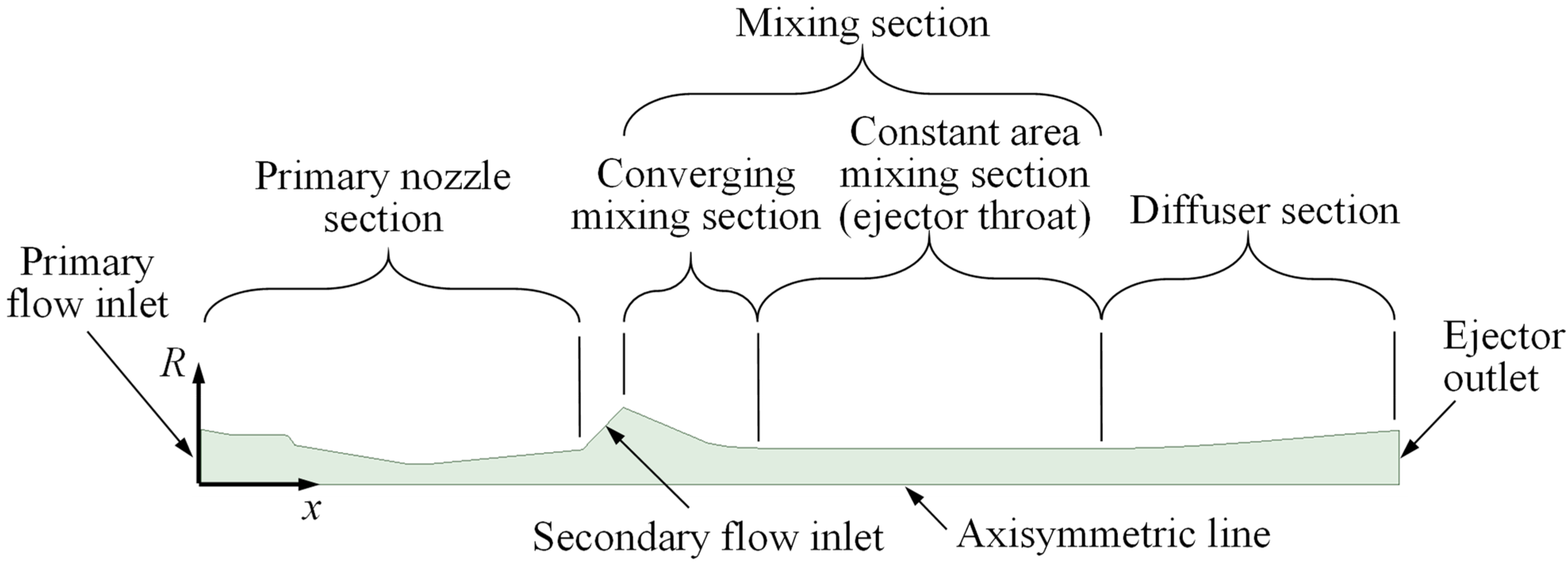
2.1. Ejector for the CFD Validation (Ejector G1)
2.2. Ejectors for the CFD Parametric Study
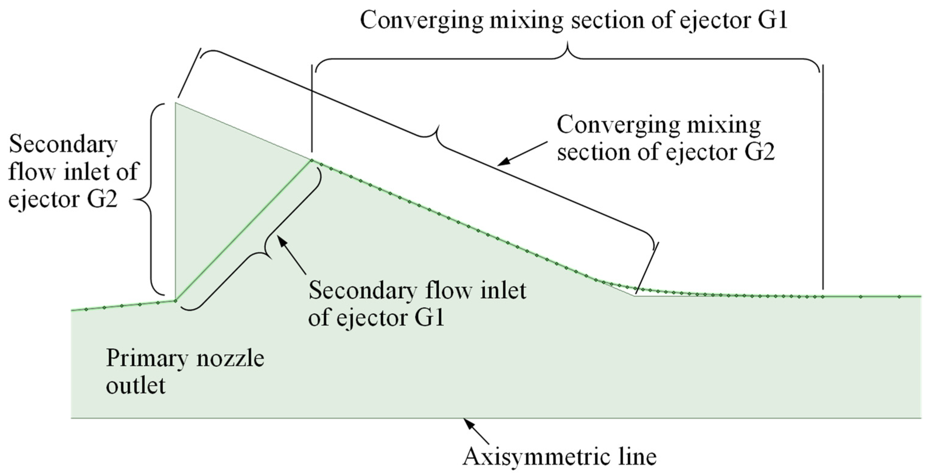
2.2.1. The Base Ejector (Ejector G2)
2.2.2. The Variation of Ejector G2
3. The CFD Settings
3.1. Numerical Set-Up
3.2. Turbulence Model
3.3. Working Fluid Properties
3.4. Boundary Conditions for the CFD Simulations
3.5. The Convergence Criteria
- The convergence of physical quantities monitored at 10 different locations.
- The mass and energy imbalance.
- Attempt to get scaled residual values of equal or less than .
- The average Mach number (facet average) along the axis located between the primary nozzle outlet plane and the ejector throat inlet plane.
- The average Mach number (facet average) along the axis of the diffuser.
- The secondary mass flow rate at the inlet.
- The mass flow rate at the outlet.
- The average wall shear stress (area-weighted average) along the primary nozzle.
- The average wall shear stress (area-weighted average) along the converging mixing section.
- The average wall shear stress (area-weighted average) along the constant-area mixing section.
- The average wall shear stress (area-weighted average) along the diffuser.
- The average static pressure (area-weighted average) along the wall of the converging mixing section.
- The static pressure at a point located at the end of converging mixing section.
4. Mesh Independence and Validation of the CFD Simulation
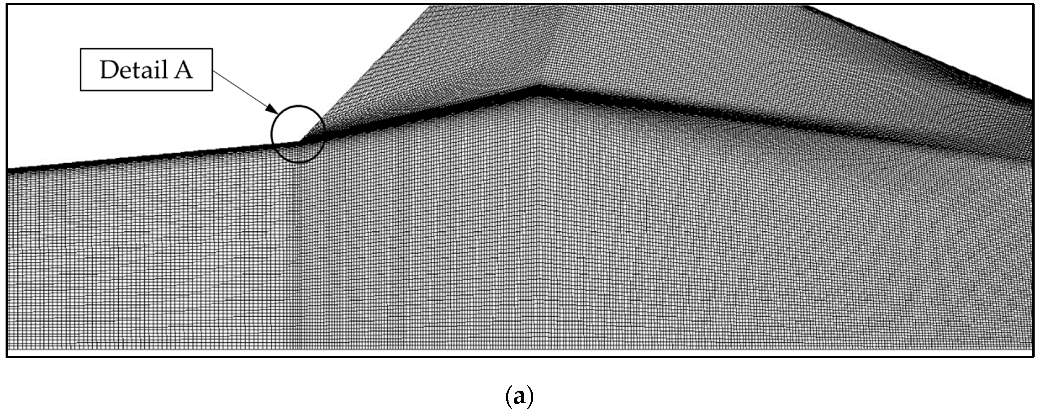
4.1. Mesh Independence Study
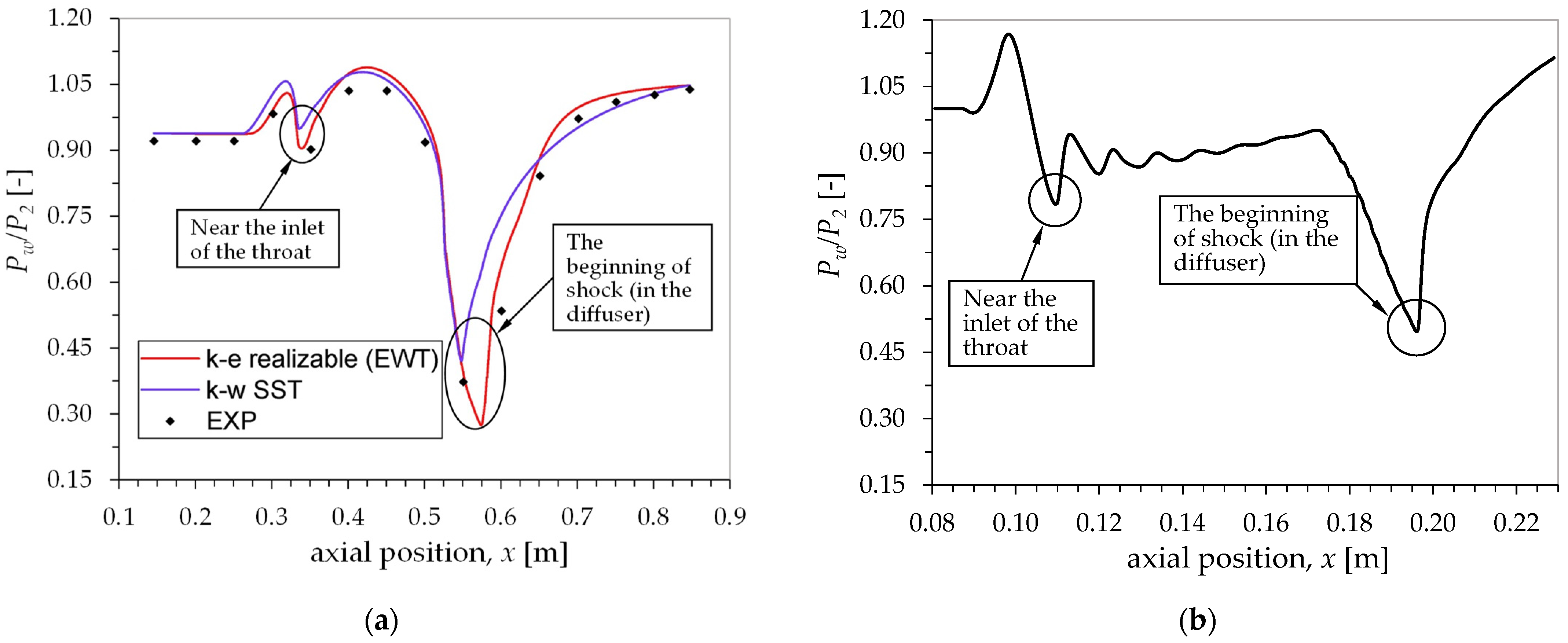
4.2. Validation
5. The One-Dimensional Analytical Model
5.1. The Standard One-Dimensional Model
- The flow is one-dimensional and steady all over the ejector.
- The fluid is an ideal gas with constant specific heats (air is used in this work as the fluid).
- Friction at the walls is negligible.
- The kinetic energy at the inlet of primary flow, inlet of secondary flow and outlet of the ejector is negligible.
- The flow at the outlet of the primary nozzle is supersonic, i.e., the flow through the primary nozzle is choked. This assumption is merely based on the practical point of view, i.e., an ejector is usually required to operate at the critical conditions at which both primary and secondary flow are choked.
- The ejector is adiabatic, rigid (no boundary work involved), and impermeable (no flow entering or leaving the ejector besides flow through the inlets and outlet of the ejector).
- The isentropic efficiency of the primary nozzle and the subsonic diffuser ( and ) is known beforehand. In this work, the values are assumed to be constant with values of 0.95 and 0.8 for the nozzle and diffuser, respectively. These values are based on the typical efficiency of the devices. However, it should be kept in mind that actually, these fixed values of efficiency cannot be applied in all operating conditions of an ejector, and they will be one of the sources of error in the model. Therefore, a study to estimate the efficiencies of the nozzle and especially, the diffuser should be conducted in the future. By doing so, their efficiencies can be estimated more accurately by just knowing the geometry and operating conditions of the ejector.
- For an ejector that operates in the critical mode, a normal shock is assumed to happen at the exit of the mixing section (station 3). Therefore, the Mach number at that location, , will be an input and have a value of one. For an ejector that operates in the sub-critical mode, the outlet static pressure, , will be an input while the will be an output. However, in this work, the focus will be on the critical mode operation and, therefore, will act as an input and as an output. It should be noted that this assumption () has been found to be inaccurate at certain operating conditions. Yet, it is simple to apply and is thought to be a good initial approximation. In fact, the value of can either be greater or less than one, depending on where the shock starts. This is a challenge that remains to be solved.
- The primary and secondary stagnation conditions (i.e., properties at station 0 and 2 in Figure 1).
- Ejector geometry:
- Primary nozzle: Throat diameter, , and outlet diameter, .
- Converging mixing section: Inlet diameter, .
- Constant area mixing section (ejector throat): Diameter, .
- Either the (for critical mode operation) or the (for sub-critical mode operation). However, the current work will focus on the critical mode operation of an ejector and, therefore, will act as an input and will be an output (assumption no. 8).
- The values of and are 0.95 and 0.8, respectively (assumption no. 7).
5.2. The Modified One-Dimensional Model
6. Results and Discussion
6.1. Pressure Variation on the Wall of the Converging Mixing Section
6.2. Secondary Mass Flow Rate Comparison
7. Conclusions
- In the CFD analysis, the transition SST turbulence model is better than the k-omega SST model in terms of how close the predicted is to the experimental data. Most of the transition SST model results are within the experimental uncertainty of Al-Ansary’s work [9], i.e., no greater than 4%. On the other hand, many of the errors of k-omega SST results are ranging from 7% to 9%. These results are obtained when the ejector is operating in the critical region.
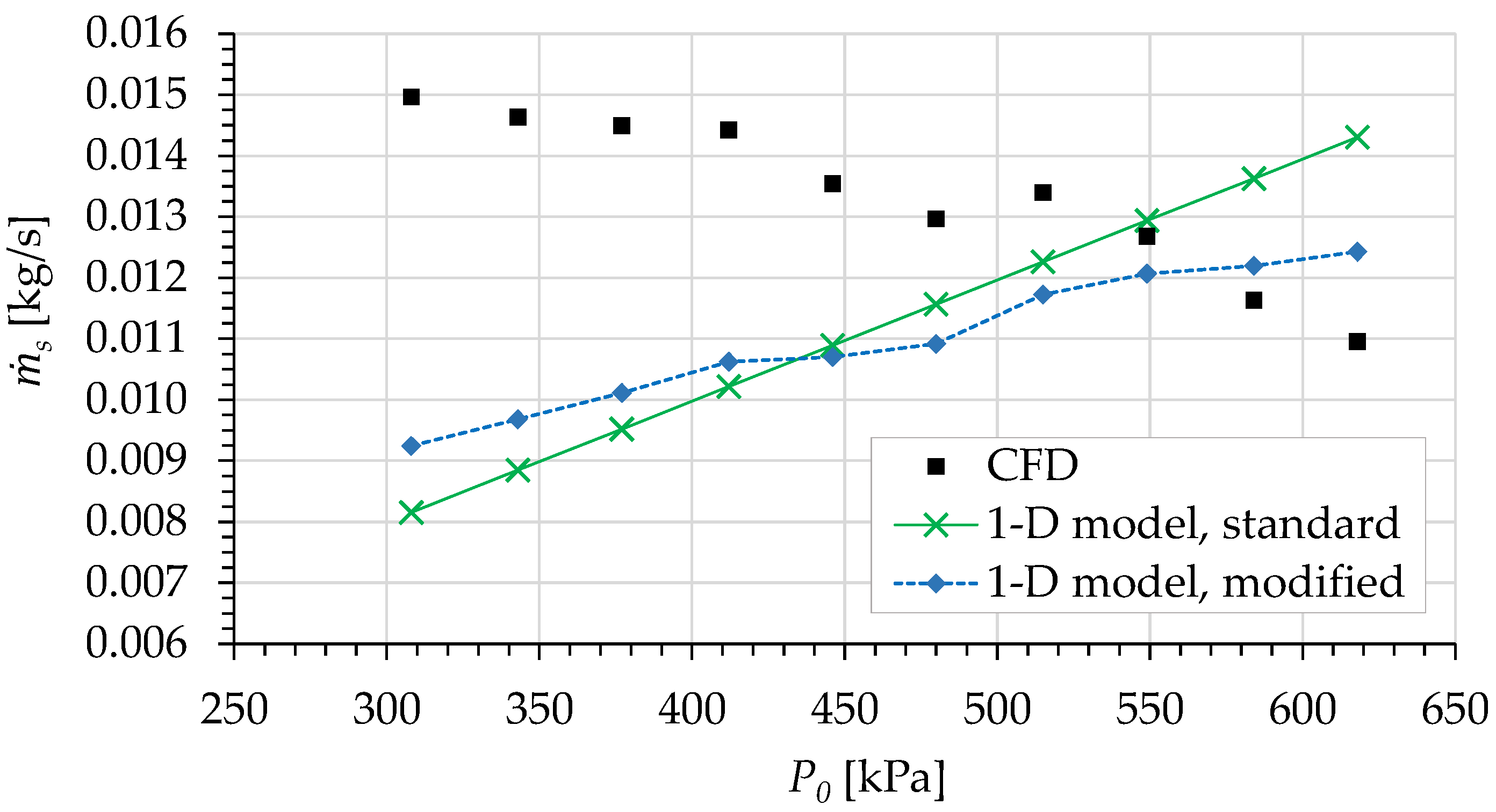
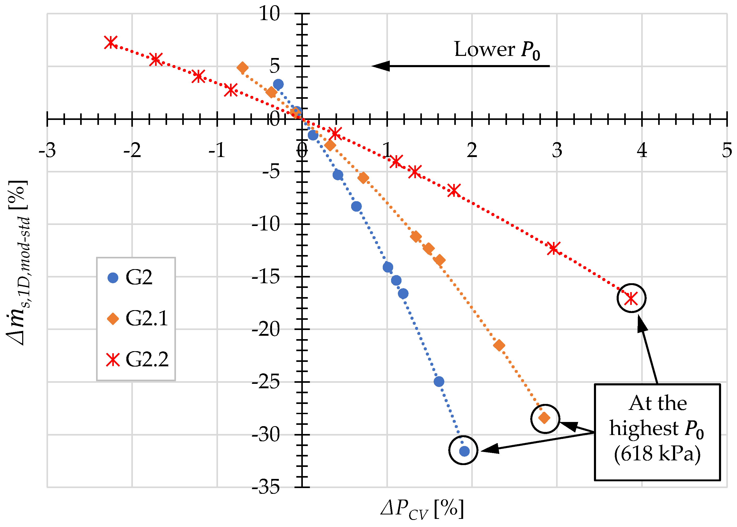
- The authors have found that the effect of wall pressure variation in the converging mixing section is actually prominent in the prediction of the one-dimensional model. Even a small amount of change in the converging wall pressure can result in a significant improvement of the model prediction of , especially at high . However, regardless of the operating conditions, the sensitivity of is high with respect to the change of the converging wall pressure, i.e., a small change in the pressure can result in a high change in . It has also been found that, in general, the inclusion of the wall pressure variation will improve the trend (slope) of the predicted . Based on these findings, this wall pressure variation should be considered in future modeling of ejectors.
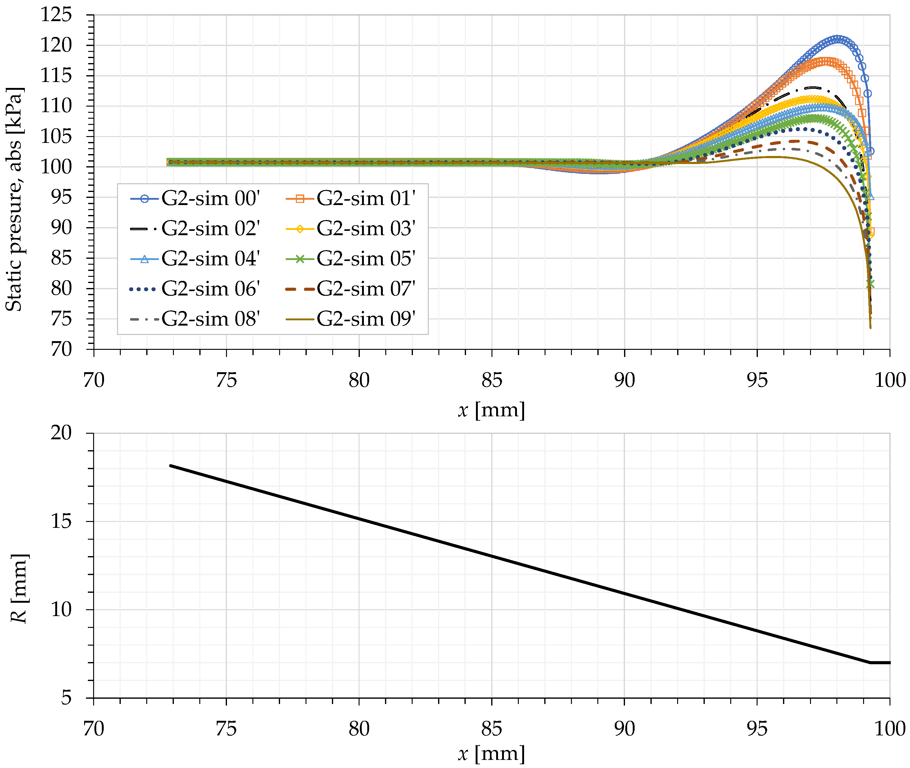
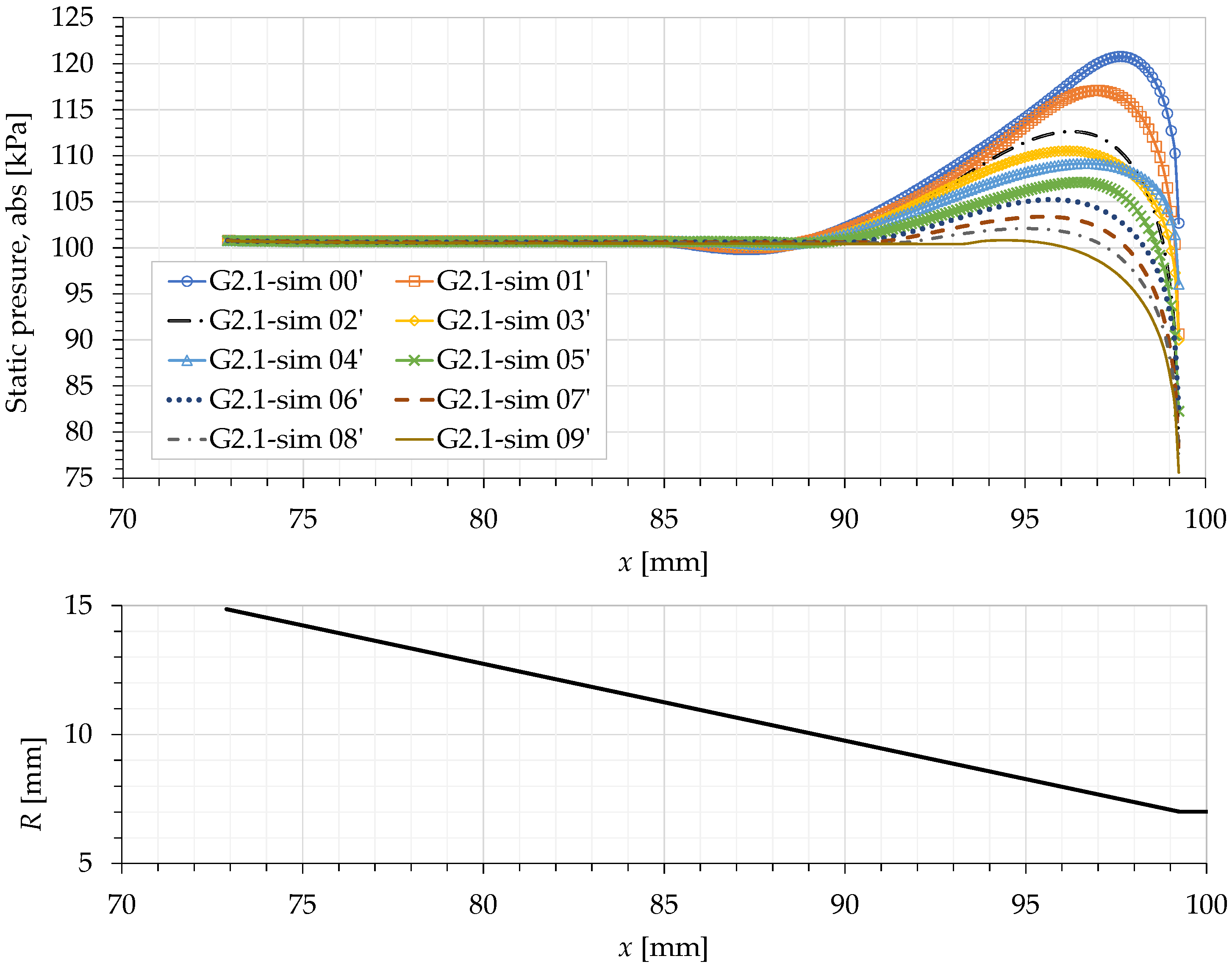
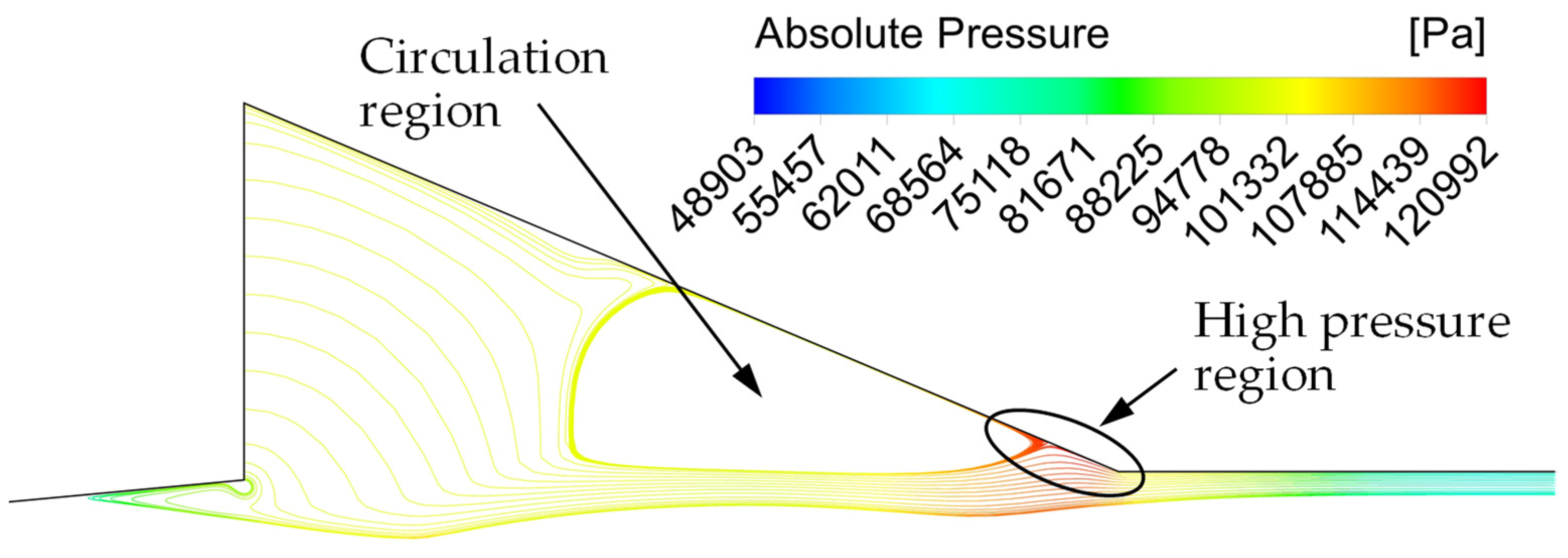
- The pressure increase on the wall of the converging mixing section is due to the impingement of the secondary flow on that wall. This happens because the shock train of the primary jet partially blocks the secondary flow as it tries to enter the ET. On the other hand, the pressure decrease at the end of that converging wall is due to the acceleration of the secondary flow as it enters the ET. The effects of these two phenomena compete each other that result in the increase or decrease of the average wall pressure. Moreover, we have also found that the behaviors of these two phenomena are linked to the primary jet speed, and the cell size and position of the shock train.
- The CFD results show that the secondary mass flow rate increases as the angle of the converging mixing section decreases. However, due to the limited range of angles simulated, the current results have not verified the existence of an optimum angle value that has been observed by other researchers.
Author Contributions
Funding
Institutional Review Board Statement
Informed Consent Statement
Data Availability Statement
Acknowledgments
Conflicts of Interest
References
- Little, A.B.; Garimella, S. A critical review linking ejector flow phenomena with component- and system-level performance. Int. J. Refrig. 2016, 70, 243–268. [Google Scholar] [CrossRef]
- Huang, B.J.; Chang, J.M.; Wang, C.P.; Petrenko, V.A. A 1-D analysis of ejector performance. Int. J. Refrig. 1999, 22, 354–364. [Google Scholar] [CrossRef]
- Keenan, J.H.; Neumann, E.P. A Simple Air Ejector. J. Appl. Mech. Trans. ASME 1942, 9, A75–A81. [Google Scholar]
- Keenan, J.H.; Neumann, E.P.; Lustwerk, F. An investigation of ejector design by analysis and experiment. J. Appl. Mech. Trans. ASME 1950, 17, 299–309. [Google Scholar]
- Chen, W.; Liu, M.; Chong, D.; Yan, J.; Little, A.B.; Bartosiewicz, Y. A 1D model to predict ejector performance at critical and sub-critical operational regimes. Int. J. Refrig. 2013, 36, 1750–1761. [Google Scholar] [CrossRef]
- Chen, W.; Liu, M.; Chong, D.; Yan, J.; Little, A.B.; Bartosiewicz, Y. Corrigendum to “A 1D model to predict ejector performance at critical and sub-critical operational regimes” [JIJR 36/6 (2013) 1750–1761]. Int. J. Refrig. 2017, 75, 177. [Google Scholar] [CrossRef]
- Kumar, N.S.; Ooi, K.T. One dimensional model of an ejector with special attention to Fanno flow within the mixing chamber. Appl. Therm. Eng. 2014, 65, 226–235. [Google Scholar] [CrossRef]
- Zhu, Y.; Cai, W.; Wen, C.; Li, Y. Shock circle model for ejector performance evaluation. Energy Convers. Manag. 2007, 48, 2533–2541. [Google Scholar] [CrossRef]
- Al-Ansary, H.A.M. Investigation and Improvement of Ejector-Driven Heating and Refrigeration Systems. Ph.D. Thesis, Georgia Institute of Technology, GA, USA, 2004. [Google Scholar]
- Al-Ansary, H.A. A Semi-Empirical One-Dimensional Model for Flow in Ejectors Used for Gas Evacuation. In Proceedings of the Fluids Engineering Division Summer Meeting, Miami, FL, USA, 17–20 July 2006; pp. 41–48. [Google Scholar] [CrossRef]
- Al-Ansary, H.A.M.; Jeter, S.M. Numerical and Experimental Analysis of Single-Phase and Two-Phase Flow in Ejectors. HvacR Res. 2004, 10, 521–538. [Google Scholar] [CrossRef]
- Mazzelli, F.; Little, A.B.; Garimella, S.; Bartosiewicz, Y. Computational and experimental analysis of supersonic air ejector: Turbulence modeling and assessment of 3D effects. Int. J. Heat Fluid Flow 2015, 56, 305–316. [Google Scholar] [CrossRef]
- Pianthong, K.; Seehanam, W.; Behnia, M.; Sriveerakul, T.; Aphornratana, S. Investigation and improvement of ejector refrigeration system using computational fluid dynamics technique. Energy Convers. Manag. 2007, 48, 2556–2564. [Google Scholar] [CrossRef]
- Bartosiewicz, Y.; Aidoun, Z.; Desevaux, P.; Mercadier, Y. Numerical and experimental investigations on supersonic ejectors. Int. J. Heat Fluid Flow 2005, 26, 56–70. [Google Scholar] [CrossRef]
- Besagni, G.; Inzoli, F. Computational fluid-dynamics modeling of supersonic ejectors: Screening of turbulence modeling approaches. Appl. Therm. Eng. 2017, 117, 122–144. [Google Scholar] [CrossRef]
- Croquer, S.; Poncet, S.; Aidoun, Z. Turbulence modeling of a single-phase R134a supersonic ejector. Part 1: Numerical benchmark. Int. J. Refrig. 2016, 61, 140–152. [Google Scholar] [CrossRef]
- Ruangtrakoon, N.; Thongtip, T.; Aphornratana, S.; Sriveerakul, T. CFD simulation on the effect of primary nozzle geometries for a steam ejector in refrigeration cycle. Int. J. Therm. Sci. 2013, 63, 133–145. [Google Scholar] [CrossRef]
- Zhu, Y.; Cai, W.; Wen, C.; Li, Y. Numerical investigation of geometry parameters for design of high performance ejectors. Appl. Therm. Eng. 2009, 29, 898–905. [Google Scholar] [CrossRef]
- Zhu, Y.; Jiang, P. Experimental and numerical investigation of the effect of shock wave characteristics on the ejector performance. Int. J. Refrig. 2014, 40, 31–42. [Google Scholar] [CrossRef]
- Hemidi, A.; Henry, F.; Leclaire, S.; Seynhaeve, J.-M.; Bartosiewicz, Y. CFD analysis of a supersonic air ejector. Part I: Experimental validation of single-phase and two-phase operation. Appl. Therm. Eng. 2009, 29, 1523–1531. [Google Scholar] [CrossRef]
- Hemidi, A.; Henry, F.; Leclaire, S.; Seynhaeve, J.-M.; Bartosiewicz, Y. CFD analysis of a supersonic air ejector. Part II: Relation between global operation and local flow features. Appl. Therm. Eng. 2009, 29, 2990–2998. [Google Scholar] [CrossRef]
- Wang, L.; Yan, J.; Wang, C.; Li, X. Numerical study on optimization of ejector primary nozzle geometries. Int. J. Refrig. 2017, 76, 219–229. [Google Scholar] [CrossRef]
- Sriveerakul, T.; Aphornratana, S.; Chunnanond, K. Performance prediction of steam ejector using computational fluid dynamics: Part 1. Validation of the CFD results. Int. J. Therm. Sci. 2007, 46, 812–822. [Google Scholar] [CrossRef]
- Dong, J.; Yu, M.; Wang, W.; Song, H.; Li, C.; Pan, X. Experimental investigation on low-temperature thermal energy driven steam ejector refrigeration system for cooling application. Appl. Therm. Eng. 2017, 123, 167–176. [Google Scholar] [CrossRef]
- Han, Y.; Wang, X.; Sun, H.; Zhang, G.; Guo, L.; Tu, J. CFD simulation on the boundary layer separation in the steam ejector and its influence on the pumping performance. Energy 2019, 167, 469–483. [Google Scholar] [CrossRef]
- Mohamed, S.; Shatilla, Y.; Zhang, T. CFD-based design and simulation of hydrocarbon ejector for cooling. Energy 2019, 167, 346–358. [Google Scholar] [CrossRef]
- Varga, S.; Soares, J.; Lima, R.; Oliveira, A.C. On the selection of a turbulence model for the simulation of steam ejectors using CFD. Int. J. Low Carbon Technol. 2017, 12, 233–243. [Google Scholar] [CrossRef][Green Version]
- Klein, S.A. Engineering Equation Solver (EES); Commercial V10.933-3D.; F-Chart Software; Available online: http://fchartsoftware.com (accessed on 5 October 2020).
- ANSYS Fluent User’s Guide, Release 19.0; ANSYS, Inc.: Canonsburg, PA, USA, 2018.
- Jeong, H.; Utomo, T.; Ji, M.; Lee, Y.; Lee, G.; Chung, H. CFD analysis of flow phenomena inside thermo vapor compressor influenced by operating conditions and converging duct angles. J. Mech. Sci. Technol. 2009, 23, 2366–2375. [Google Scholar] [CrossRef]









| Properties | Values/Equations |
|---|---|
| Density, | Ideal gas |
| Specific heat, | 1006.43 J/kg.K |
| Thermal conductivity, | [W/m.K]; where is in Kelvin |
| Viscosity, | [Pa.s]; where in Kelvin |
| Mesh Name | Number of Cells | k-Omega SST | Transition SST | k-Omega SST | Transition SST | ||||
|---|---|---|---|---|---|---|---|---|---|
| Coarse | 112,959 | 0.07104 | 0.01212 | 0.07107 | 0.01156 | 0.00 | 0.00 | 0.00 | 0.00 |
| Medium | 151,834 | 0.07104 | 0.01211 | 0.07108 | 0.01157 | 0.00 | −0.08 | 0.01 | 0.09 |
| Semi-fine | 452,760 | 0.07102 | 0.01212 | 0.07106 | 0.01161 | −0.03 | 0.00 | −0.01 | 0.43 |
| Fine | 902,069 | 0.07102 | 0.01211 | 0.07106 | 0.01163 | −0.03 | −0.08 | −0.01 | 0.61 |
| Sim. no. | ||||||
|---|---|---|---|---|---|---|
| Exp. | Transition SST | k-Omega SST | Transition SST | k-Omega SST | ||
| 0 | 618 | 0.01189 | 0.01157 | 0.01211 | -2.69 | 1.85 |
| 1 | 584 | 0.01206 | 0.01195 | 0.01315 | -0.91 | 9.04 |
| 2 | 549 | 0.01240 | 0.01177 | 0.01284 | -5.08 | 3.55 |
| 3 | 515 | 0.01286 | 0.01204 | 0.01290 | -6.38 | 0.31 |
| 4 | 480 | 0.01308 | 0.01281 | 0.01349 | -2.06 | 3.13 |
| 5 | 446 | 0.01320 | 0.01340 | 0.01433 | 1.52 | 8.56 |
| 6 | 412 | 0.01342 | 0.01350 | 0.01439 | 0.60 | 7.23 |
| 7 | 377 | 0.01365 | 0.01362 | 0.01472 | -0.22 | 7.84 |
| 8 | 343 | 0.01382 | 0.01383 | 0.01491 | 0.07 | 7.89 |
| 9 | 308 | 0.01399 | 0.01425 | 0.01527 | 1.86 | 9.15 |
| Sim. No. | ||||||
|---|---|---|---|---|---|---|
| Exp. | Transition SST | k-Omega SST | Transition SST | k-Omega SST | ||
| 0 | 618 | 0.06713 | 0.07108 | 0.07104 | 5.88 | 5.82 |
| 1 | 584 | 0.06464 | 0.06717 | 0.06713 | 3.91 | 3.85 |
| 2 | 549 | 0.06087 | 0.06314 | 0.06310 | 3.73 | 3.66 |
| 3 | 515 | 0.05716 | 0.05923 | 0.05919 | 3.62 | 3.55 |
| 4 | 480 | 0.05325 | 0.05520 | 0.05516 | 3.66 | 3.59 |
| 5 | 446 | 0.04931 | 0.05129 | 0.05125 | 4.02 | 3.93 |
| 6 | 412 | 0.04543 | 0.04738 | 0.04733 | 4.29 | 4.18 |
| 7 | 377 | 0.04150 | 0.04335 | 0.04331 | 4.46 | 4.36 |
| 8 | 343 | 0.03768 | 0.03943 | 0.03940 | 4.64 | 4.56 |
| 9 | 308 | 0.03397 | 0.03540 | 0.03537 | 4.21 | 4.12 |
| Sim no. | Ejector G2 | Ejector G2.1 | Ejector G2.2 | |||||||
|---|---|---|---|---|---|---|---|---|---|---|
| ∆PCV 1 [%] | 2 [%] | ∆PCV 1 [%] | 2 [%] | ∆PCV 1 [%] | 2 [%] | |||||
| 1-D, std | 1-D, mod | 1-D, std | 1-D, mod | 1-D, std | 1-D, mod | |||||
| 0’ | 618 | 1.91 | 43.43 | 11.84 | 2.85 | 41.03 | 12.62 | 3.87 | 30.47 | 13.41 |
| 1’ | 584 | 1.61 | 27.86 | 2.91 | 2.32 | 24.82 | 3.30 | 2.96 | 17.20 | 4.90 |
| 2’ | 549 | 1.19 | 9.39 | −7.19 | 1.62 | 6.42 | −7.00 | 1.79 | 1.89 | −4.89 |
| 3’ | 515 | 1.11 | 2.77 | −12.57 | 1.49 | −0.08 | −12.39 | 1.11 | −8.51 | −12.54 |
| 4’ | 480 | 1.01 | −2.45 | −16.53 | 1.34 | −4.93 | −16.11 | 1.33 | −10.79 | −15.81 |
| 5’ | 446 | 0.64 | −14.59 | −22.90 | 0.72 | −16.49 | −22.09 | 0.39 | −19.57 | −20.97 |
| 6’ | 412 | 0.42 | −22.28 | −27.60 | 0.33 | −24.69 | −27.19 | −0.84 | −29.18 | −26.40 |
| 7’ | 377 | 0.13 | −30.00 | −31.54 | −0.08 | −31.61 | −31.03 | −1.22 | −34.30 | −30.23 |
| 8’ | 343 | −0.06 | −36.01 | −35.29 | −0.36 | −37.28 | −34.73 | −1.72 | −39.55 | −33.88 |
| 9’ | 308 | −0.28 | −42.85 | −39.55 | −0.70 | −43.91 | −39.02 | −2.25 | −45.56 | −38.28 |
| Sim. no. | ||||||
|---|---|---|---|---|---|---|
| Ejector G2 | Ejector G2.1 | Ejector G2.2 | Ejector G2.1 | Ejector G2.2 | ||
| 0’ | 618 | 0.00997 | 0.01014 | 0.01096 | 1.71 | 9.93 |
| 1’ | 584 | 0.01066 | 0.01092 | 0.01163 | 2.44 | 9.10 |
| 2’ | 549 | 0.01182 | 0.01215 | 0.01269 | 2.79 | 7.36 |
| 3’ | 515 | 0.01193 | 0.01227 | 0.01340 | 2.85 | 12.32 |
| 4’ | 480 | 0.01186 | 0.01217 | 0.01297 | 2.61 | 9.36 |
| 5’ | 446 | 0.01275 | 0.01304 | 0.01354 | 2.27 | 6.20 |
| 6’ | 412 | 0.01315 | 0.01357 | 0.01443 | 3.19 | 9.73 |
| 7’ | 377 | 0.01360 | 0.01392 | 0.01449 | 2.35 | 6.54 |
| 8’ | 343 | 0.01383 | 0.01411 | 0.01464 | 2.02 | 5.86 |
| 9’ | 308 | 0.01426 | 0.01453 | 0.01497 | 1.89 | 4.98 |
Publisher’s Note: MDPI stays neutral with regard to jurisdictional claims in published maps and institutional affiliations. |
© 2021 by the authors. Licensee MDPI, Basel, Switzerland. This article is an open access article distributed under the terms and conditions of the Creative Commons Attribution (CC BY) license (https://creativecommons.org/licenses/by/4.0/).
Share and Cite
Djajadiwinata, E.; Sadek, S.; Alaqel, S.; Orfi, J.; Al-Ansary, H. Numerical and One-Dimensional Studies of Supersonic Ejectors for Refrigeration Application: The Significance of Wall Pressure Variation in the Converging Mixing Section. Appl. Sci. 2021, 11, 3245. https://doi.org/10.3390/app11073245
Djajadiwinata E, Sadek S, Alaqel S, Orfi J, Al-Ansary H. Numerical and One-Dimensional Studies of Supersonic Ejectors for Refrigeration Application: The Significance of Wall Pressure Variation in the Converging Mixing Section. Applied Sciences. 2021; 11(7):3245. https://doi.org/10.3390/app11073245
Chicago/Turabian StyleDjajadiwinata, Eldwin, Shereef Sadek, Shaker Alaqel, Jamel Orfi, and Hany Al-Ansary. 2021. "Numerical and One-Dimensional Studies of Supersonic Ejectors for Refrigeration Application: The Significance of Wall Pressure Variation in the Converging Mixing Section" Applied Sciences 11, no. 7: 3245. https://doi.org/10.3390/app11073245
APA StyleDjajadiwinata, E., Sadek, S., Alaqel, S., Orfi, J., & Al-Ansary, H. (2021). Numerical and One-Dimensional Studies of Supersonic Ejectors for Refrigeration Application: The Significance of Wall Pressure Variation in the Converging Mixing Section. Applied Sciences, 11(7), 3245. https://doi.org/10.3390/app11073245


