Abstract
This work deals with the safety analysis of an air data system (ADS) partially based on synthetic sensors. The ADS is designed for the small aircraft transportation (SAT) community and is suitable for future unmanned aerial vehicles and urban air mobility applications. The ADS’s main innovation is based on estimation of the flow angles (angle-of-attack and angle-of-sideslip) using synthetic sensors instead of classical vanes (or sensors), whereas pressure and temperature are directly measured with Pitot and temperature probes. As the air data system is a safety-critical system, safety analyses are performed and the results are compared with the safety objectives required by the aircraft integrator. The present paper introduces the common aeronautical procedures for system safety assessment applied to a safety critical system partially based on synthetic sensors. The mean time between failures of ADS’s sub-parts are estimated on a statistical basis in order to evaluate the failure rate of the ADS’s functions. The proposed safety analysis is also useful in identifying the most critical air data system parts and sub-parts. Possible technological gaps to be filled to achieve the airworthiness safety objectives with nonredundant architectures are also identified.
1. Introduction
An innovative, digital, modular, and fully integrated air data system (ADS) is designed and manufactured for the small aircraft transportation (SAT) community that belongs to the CS-23 category [1], suitable for fly-by-wire (FBW) applications. The proposed certifiable ADS is partially based on synthetic sensors [2] and can be easily extended to other aircraft categories, such as unmanned aerial vehicles (UAV) or urban air mobility (UAM) vehicles. The present work is conducted following guidelines from ARP4754 [3] that define recommended practices for development and safety assessment processes for avionic systems. The practices prescribed by these documents are recognized by the airworthiness authorities (e.g., European Aviation Safety Agency (EASA)) as acceptable means for showing compliance with airworthiness regulations [1,4]. Typically, a simplex air data system (ADS) is made up of external (i.e., protruding from the aircraft fuselage) parts, such as probes and vanes. The air data functions (ADFs) shall calculate all air parameters as required by the standard AS8002 [5] from direct measures of the following:
- local static pressure, ;
- local dynamic pressure, ;
- local air temperature (static, , or total, );
- local angle of attack, or AoA;
- local angle of sideslip, or AoS.
Synthetic sensors are researched extensively in the academic field of air data, but there are no examples of synthetic sensors certified for civil operations. Air data synthetic sensors are mainly used as (1) Pitot-free aircraft speed estimators [6], (2) vane/sensor-free flow angle estimators [7], and (3) Pitot and vane/sensor-free for both airspeed and flow angle estimators [8].
As the avionic background is mature to welcome such innovations on board, synthetic solutions can be replaced or added to physical (or mechanical) sensors in order to analytically increase the system redundancy [9,10,11,12]. Another chance is to use synthetic sensors to monitor physical sensors and to accommodate possible failures [13,14,15]. In fact, the concurrent use of dissimilar sources of the same air data (physical and synthetic ones) can be beneficial to solve some issues related to common failure modes or incorrect failure diagnosis of a modern air data system [16,17].
As far as the flow angle estimation is concerned, the first example can be found in [18,19] and recently in [11,20,21,22,23,24,25]. Model-based (e.g., Kalman filter), data-driven (e.g., neural networks), and model-free [26,27] are the approaches commonly used. The proposed ADS employs flow angle synthetic sensor based on pretrained neural networks [28] because (1) their determinism (e.g., with respect to Kalman filters) would ease the certification process and (2) low computational effort is required (e.g., with respect to fuzzy approaches [29]).
The present paper presents a safety analysis of the ADS with a nonredundant (or simplex) architecture. In fact, the objective of the present work is to assess if the simplex ADS can meet the required specifications and, on the other hand, identify the most critical air data system parts and sub-parts to identify possible technological gaps to fill in order to achieve the airworthiness safety objectives with a nonredundant architecture.
This paper begins with a description of the standard procedures followed to perform the safety analysis in Section 2. The ADS is introduced to describe all parts and features in Section 3. The ADS parts’ failure rates (FRs) are evaluated in Section 4. The safety analysis is presented in Section 2, where the results related to the simplex ADS are evaluated and then compared to the safety objectives in order to establish whether a simplex configuration could satisfy the safety requirements. The main outcomes of the present work are collected in Section 6.
2. Safety Analysis Approach
From a system point of view, the ADS shall satisfy the applicable airworthiness specifications in order to guarantee the defined safety level in terms of failure events per flight hour with respect to any basic ADS functionalities. The safety assessment guidelines from ARP4761 are considered for the safety analysis presented in the present work.
The certification specifications for commuter aircraft [1], applicable to the proposed ADS, defines the event severity and related probability. Failure conditions are classified according to the severity of their effects such as the following:
- No Safety Effect: failure conditions that have no effect on safety (i.e., that do not affect the operational capability of the aeroplane or increase the crew workload).
- Minor: failure conditions that do not significantly reduce aeroplane safety and that involve crew actions that are well within their capabilities. Minor failure conditions may include, for example, a slight reduction in safety margins or functional capabilities; a slight increase in crew workload, such as routine flight plan changes; or some physical discomfort to passengers or the cabin crew.
- Major: failure conditions that reduce the capability of the aeroplane or the ability of the crew to cope with adverse operating conditions to the extent that there would be, for example, a significant reduction in safety margins or functional capabilities, a significant increase in crew workload or in conditions impairing crew efficiency, discomfort to the flight crew, or physical distress to passengers or cabin crew, possibly including injuries.
- Hazardous: failure conditions that reduce the capability of the aeroplane or the ability of the crew to cope with adverse operating, conditions to the extent that there would be
- (a)
- a large reduction in safety margins or functional capabilities,
- (b)
- physical distress or excessive workload such that the flight crew cannot be relied upon to perform their tasks accurately or completely, or
- (c)
- serious or fatal injury to a relatively small number of the occupants other than the flight crew.
- Catastrophic: Failure conditions that would result in multiple fatalities, usually with the loss of the aeroplane.
Generally speaking, the airworthiness specifications deal with the probability of occurrence of the listed failure conditions in qualitative terms:
- Probable: when a failure condition is expected to occur one or more times during the entire operational life of each aeroplane.
- Remote: when a failure condition is expected to unlikely occur to each aeroplane during its total life but may occur several times when considering the total operational life of a number of aeroplanes of the same type.
- Extremely Remote: when a failure condition is expected to unlikely occur to each aeroplane during its total life but may occur a few times when considering the total operational life of all aeroplanes of the same type.
- Extremely Improbable: when a failure condition is so unlikely that it is not expected to occur during the entire operational life of all aeroplanes of one type.
As a general guideline for reliability/safety objectives, airworthiness specification follows a logical relationship between the average probability per flight hour and the severity of failure condition effects [1] as follows:
- failure conditions with no safety effects have no reliability safety requirement;
- failure conditions with minor effects may be probable;
- failure conditions with major effects must be no more frequent than remote;
- failure conditions with hazardous effects must be no more frequent than extremely remote;
- failure conditions with catastrophic effects must be extremely improbable;
For each aircraft type (or category), the applicable airworthiness standards quantify the probability of occurrence in order to give clear targets for system reliability/safety analysis. It is obvious that a safety critical system must be designed with extremely improbable failure conditions that can lead to a catastrophic event. The numerical value of the corresponding probability of occurrence per flight hour is related to the aircraft category and its mission. For example, the CS25 and FAR25 aircraft categories demonstrate that the catastrophic event is less than per flight hour. As far as the proposed ADS is concerned, quantification of the probability of occurrence per flight hour is imposed by the aircraft integrator’s system specification document [30] as follows:
- loss (or undetected, annunciated loss) air data function shall be less than ;
- erroneous (or detected, unannuciated loss) air data function shall be less than .
In the present work, the ADS is studied from a safety point of view considering only nominal operations or loss of functionalities, whereas degraded performances are not addressed here.
The Functional Hazard Assessment (FHA) is the first step in the safety analysis process [31] performed by the aircraft integrator at the aircraft level. At the system level, the FHA is performed in order to identify failure conditions and to classify them at the aircraft level, in agreement with the A/C integrator, according to their severity. Classification of the failure conditions establishes the safety requirements (or objectives) that the operative ADS shall meet. As an example, possible loss of the air data function of airspeed calculation are evaluated and classified in accordance with its effect at the aircraft level.
The second step [31] is the Preliminary System Safety Assessment (PSSA), with the allocation of system function (from the FHA safety objectives) to system items. Item safety requirements are then allocated to a lower level (hardware and software). This allocation to system items is performed using the Fault Tree Analysis (FTA) method with the aim of determining the item reliability requirements. To this purpose, the FTA can be built following the top-down or bottom-up approaches [31]. In the first case, the defined functional safety requirement (at the top level) is split down to the single items, whereas in the second case, from known sub-items’ failure rates, reliabilities at higher levels are derived up to the top level function.
These two steps represent a standard top-down approach [31]: from the safety requirements at the system level (FHA), several safety objectives are derived for the single system items (PSSA).
On the other hand, the bottom-up analysis is used in the system safety assessment (SSA) that verifies if the selected system architecture meets the safety requirements as defined in the FHA and PSSA. The SSA exploits the results of other analysis, such as the Failure Modes and Effect Analysis (FMEA), able to identify failure modes and rates of system items and their effects at higher levels. As an example, the FMEA could provide very low-level analyses of how the failure rate of a single sub-item is derived, while the FTA of SSA will propagate those characteristics to higher levels (e.g., item) and again to the system functionality (e.g., airpseed calculation).
As a final step [31], the SSA results are compared with the PSSA objectives in order to evaluate possible redesign at the system level (e.g., change items) or at the aircraft level (e.g., redundancy).
2.1. Failure Rate Derivation via Fault Tree Analysis
An avionic system’s failure rate should consider all possible failure and degradation modes derived from all its parts. For the present safety analysis, two possible failure conditions are considered for the air data system functions: (1) loss (i.e., undetected or unannuciated loss) and (2) erroneous (i.e., detected or annunciated loss).
With the SSA, FTAs are analysed for each ADF in order to calculate the quantitative failure rates of air data functions at the system level. The known failure rate is imposed at the lowest level (e.g., failure of one of the identified ADS sub-parts), and the ADS function’s safety budget is calculated using a bottom-up approach.
2.2. Reliability Requirements Derivation via Fault Tree Analysis
From the FHA, the most critical conditions (MCCs) are identified. With the PSSA, FTAs are developed for each MCC in order to calculate the quantitative safety objectives to be allocated to the single ADS parts or sub-parts. The safety requirement is imposed at the top level event (e.g., loss of one of the identified air data functions at the system level). The safety budget of ADS parts and sub-parts is calculated using a top-down approach. The assumption for the top-down approach is based on equal probabilities allocated to output events from AND/OR nodes as described in Figure 1. This is common approach for preliminary design phases, as there are no well-defined information about the system components.
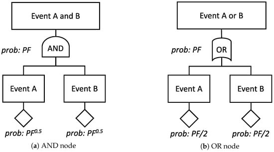
Figure 1.
Rationale of the failure rate calculation for the “top-down” approach.
2.3. Flight Phases
The aircraft mission is typically made up of takeoff (T/O), climb, cruise, descent, and landing (LAND) phases that can be further grouped into on-ground and in-flight phases [32]. Any flight phase is characterized by the particular aircraft type and mission. For example, UAV can have a very long cruise phase if compared to a UAM vehicles, where the cruise will be comparable to the T/O and LAND phases. This aspect is crucial to establish the safety objectives and possible mitigation actions when the FHA is defined. For the aim of the present work, all possible flight phases are grouped as reported in Table 1.

Table 1.
Flight phases.
In normal operations, the air data system shall be operative along all the A/C flight missions both on ground and in air segments.
3. Air Data System Description and Functions
As described in Figure 2b, the air data system partially based on synthetic sensors is made up of three main parts: (1) air data computer (ADC), (2) external Pitot probe (or Prandtl tube), and (3) external total air temperature probe. The TAT probe is equipped with dual sensing elements and anti-icing heaters. For the sake of generality, the TAT probe can be replaced with an Outside Air Temperature (OAT) if the operating Mach number is lower than . The choice of two sensing elements is not crucial but it is exploited to detect sensing element failures at the ADS level. All other failures (cables, heaters, etc.) can only be detected at the aircraft level with ADS redundancy.
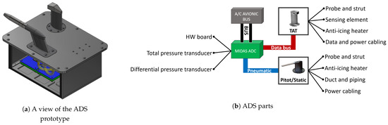
Figure 2.
Overview of the proposed air data system (ADS): architecture and parts.
The Pitot probe is equipped with anti-icing heaters, whereas the sensing elements, i.e., absolute and differential pressure transducers, are housed in the ADC. Moreover, the Pitot probe has a very short pneumatic (less than 10 ), metallic connection ducts from the probe. The TAT probe is equipped with a redundant analog sensing elements connected to the ADC by means of wires. Both the Pitot and TAT probes have power connections for anti-icing purposes. Figure 2b describes the interactions among the main ADS sub-parts. The Pitot probe is made up of (1) the total pressure tube with static holes and (2) integrated heaters for anti-icing purposes. The TAT is made up of (1) the total temperature probe, (2) an integrated heater for anti-icing, and (3) two integrated sensing elements.
The ADC is split into the following sub-parts: (1) two boards with hardware (HW) components (resistors, capacitors, etc.), (2) absolute pressure transducers, and (3) differential pressure transducers. The ADC board based on FPGA [33] encompasses all the necessary hardware and software functionalities compliant with applicable airworthiness standards [5]. For example, the ADC shall be able to apply pressure and temperature calibration algorithms in order to convert the local measurements into freestream measurements with the required accuracy.
3.1. Synthetic Sensor Description
The proposed ADS is a single line replaceable unit (LRU) embedding a synthetic sensor, dedicated to AoA and AoS estimation based on a patented technology at TRL6 [34]. A prototype overview is represented in Figure 2a. The synthetic sensors are essentially state observers for which the A/C flight dynamic model is replaced by a model based on neural networks [35].
Exploiting the advantages of the fly-by-wire (FBW) technology, the air data system will receive, as input, consolidated data from the avionic bus (introduced in Section 3.2) to be fused with measured ones (introduced in Section 3) in order to estimate AoA and AoS with high reliability, as schematically presented in Figure 3b.
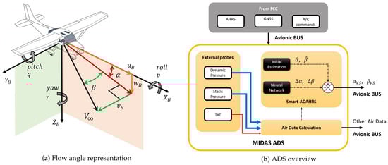
Figure 3.
Aircraft model and ADS scheme.
The synthetic sensors rely on a pretrained (i.e., deterministic) neural network and the use of A/C data from the attitude and heading reference system, primary surface commands/deflections, and a Global Navigation Satellite System (GNSS). The neural network consists of a biased linear combination of nonlinear activation functions. Each activation function is driven by a biased linear combination of the output of the preceding nodes. The multilayer perceptron (MLP) can be described as a nonlinear map between the input and the target. The training stage has the aim to find weights of the network that better fit the desired map. The MLP approach is mathematically proven using the universal approximation theorem. In fact, it is proven that any continuous function of n real variables, with support in the unit hypercube, can be uniformly approximated by finite superposition of a fixed, univariate function that is discriminatory [36].
The synthetic sensors deal with a very straightforward model, suitable for real-time and cost-effective innovative avionic systems. Consider the following assumption on AoA and AoS valid:
where and are initial estimations obtained with flight mechanics equations, whereas and are the differences between the linear estimations and the true values of Figure 3a. According to a patented procedure [37], and are augmented with the evaluation of and based on two MLPs, which process measurements obtained with non-protruding sensors (except for the Pitot tube and TAT). and can be evaluated as follows:
where stands for the pitch angle, stands for the flight path angle, is the proper acceleration as measured by the accelerometer along the axis, and is the impact pressure. K is an A/C constant derived from flight mechanic considerations.
Mathematical demonstrations exist [36,38,39,40,41,42] about the MLP performing as a universal approximator. During the training procedure, the weights of the linear combinations are estimated when solving the nonconvex problem of the error function optimization, for which different heuristic rules exist. The Levenberg–Marquard (LM) algorithm is used in this work. The complete input vector needed by the synthetic sensors includes data from the GPS (providing ), the ADS, and the attitude and heading reference system (AHRS). The synthetic sensors considered in this work have the following characteristics:
- feed-forward neural network,
- one hidden layer with 24 neurons,
- neurons with sigmoidal activation functions,
- one output layer with a single (or double for the VS–A&S) linear neuron, and
- limited output during the operative life.
The following input vectors are hence implemented:
where is the true airspeed; , , are the accelerations measured by the accelerometers, respectively, in the , , and axes; , , and are the Euler angles; p, q, and r are the body angular rates; is the initial estimation for the AoA; and , , , , , and are the elevator, aileron, rudder, throttle, differential throttle, and horizontal stabilizer commands.
3.2. Air Data Computer Description
The ADC encompasses two solid-state pressure transducers (absolute and differential ones), all necessary hardware components for power management and distribution to the probes, avionic bus interface capabilities with the A/C flight control system (FCS), and calculation functionalities. For evaluation of the ADC’s mean time between failures (MTBF), the ADC is split into (1) two redundant (dual) main boards (FPGA, resistors, capacitors, etc.) (2) one absolute pressure transducer, and (3) one differential pressure transducer.
The choice of a redundant board guarantees limited capabilities to identify failures at the ADS level. In fact, the ADC can perform a Built-in-Test (BIT) in order to evaluate its operative status. Therefore, the ADS can operate in normal mode or emergency mode according to the results of the internal BIT. In normal mode, the ADC provides the flight control computer (FCC) with a complete message containing its own status validity, whereas in emergency mode, the ADC declares itself in failure with predefined output messages. The ADC has the following characteristics:
- The HW is compliant to DO-254 level B certification.
- The chosen FPGA in the HW is single event upset (SEU) immune and is used to configure I/Os and other HW critical aspects.
- The ADC contains two redundant boards. In case of a serious failure that could involve permanent damage to the nominal board, the redundant one switches off all the nominal internal supplies, reporting the failure to the avionic system.
- The HW communication link to FCC using CANaerospace Revision is in the form of the CANB (29-bit identifiers) format with 1 Mbit/s bus speed. Nominal and redundant links are implemented in order to prevent a single failure event.
- The HW provides provisional link ARINC-664 (AFDX) for alternative use in CANaerospace with (a) redundancy management, (b) an integrity checker, and (c) deterministic packet delivery.
3.3. Internal Redundancy Management
Generally speaking, the simplex (or nonredundant) ADS cannot provide full redundancy capabilities because, as typically done, it is meant for system redundancy at the aircraft level. However, the ADS can provide limited redundancy capabilities through the identification of failures of the TAT sensing elements and the HW components. In particular, possible failures to the TAT-independent sensing elements are detected by the ADC by direct comparison, whereas internal failures (electric or processing) are detected by the ADC using master–slave logics, following a declaration of the failed status on the avionic bus.
Even though the ADC features a dual board, the pressure transducers and the external probes are single, mainly due to volume constraints, and represent a single point of failure.
3.4. ADS Functionalities
The ADS can directly measure (1) local static pressure, (2) local dynamic pressure, and (3) local total air temperature. In contrast, the ADS can estimate (without using any dedicated physical vane/probe) (1) the freestream angle of attack and (2) the freestream angle of sideslip. From these five main air data (three measured and two estimated), the air data system can calculate all the air data necessary to be compliant with [5]. Table 2 collects the main air data functionalities of the ADS and possible effects from the total loss of the single function. Among all data, airspeeds (e.g., CAS and TAS), pressure altitude, and vertical speed are the most relevant, whereas the measure of the angle of attack is typically used for stall prevention [43] or flight control laws. In fact, the AoA accuracy requirements are typically derived from flight mechanics, control, and/or manoeuvrability considerations. As far as AoS is concerned, the standard AS8002A [5] does not prescribe any requirements. The AoS measure and accuracy requirements are only derived from flight mechanics, control, and/or manoeuvrability considerations.
Table 2.
ADS function requirements and loss effects.
It is worth highlighting that local air temperature measures are calibrated using airspeed or Mach number information. Therefore, any loss in speed indications causes a degradation in the measurement of the freestream air temperature.
Table 3 provides the dependency between air data functionalities and the ADS main parts.
Table 3.
ADS decomposition and functional requirement allocation to main parts. “X” represents a full loss, whereas “x” is a degraded function.
As far as degraded ADFs are concerned, they are not considered in this work because they would require a dedicated sensitivity analysis. In other words, even though the loss of a TAT probe (or its main related function ADF2) affects the synthetic estimation of AoA and AoS, data degradation will be considered within the acceptance limits. The loss of ADF1 (pressure measurements) will affect the temperature calibration. Even in this case, the degradation will be considered acceptable.
4. MTBF Evaluation
The MTBF of any ADS parts is derived statistically based on [44] or, when available, from part manufacturers. Reference [44] provides failure rate data for a wide variety of component types including mechanical, electromechanical, and electronic assemblies. Statistical data are useful to derive MTBF of the single sub-part in order to highlight the MTBF genesis of the Pitot probe, TAT probe, and the ADC. The results from [45] are collected in Table 4. Considering that metallic ducts, pneumatic connections, power, and data connections have a low failure rate (FR), they are grouped as a single sub-part in the present analysis.
Table 4.
ADS parts and related mean time between failure (MTBF) declared by the part manufacturer, whereas the sub-part MTBF is retrieved from [44] and the “Estimated MTBF” is calculated using Equation (9).
The failure rate is calculated as the ratio between the observed fails and one million operating hours. Therefore, the MTBF can be calculated if not available from the manufacturer by multiplying times the probability of failure occurrence (PF) from [44]. On the other hand, the probability of a failure occurrence per flight hour, or the FR, can be calculated as the inverse of the MTBF as
As an example, the TAT integrated heater has . The corresponding MTBF is 33,223 flight hours, whereas the FR is about per flight hour. As Equation (8) refers to a single ADS sub-part, considering that the sub-part failure events are independent (i.e., in OR conditions), the ADS part’s MTBF is calculated as
where is the FR of jth sub-part of the ADS part calculated in Equation (8).
From Table 4, it can be noticed that both estimated MTBF for the Pitot and TAT are comparable with the manufactures data. The subdivision of ADS parts into sub-parts, with the consequent MTBF evaluation, is crucial to single out and evaluate the sub-parts that are the most critical with respect to safety. In fact, for the Pitot probe, the leading sub-part is the heater element (used for anti-icing purposes) with a FR of the order of magnitude of , whereas for the TAT probe, both the heater and the dual sensing element are the most critical sub-parts. On the other hand, both the metallic tubes and the pneumatic/data/power connections have an FR of the order of magnitude of , i.e., at least two orders of magnitude higher.
As far as a conventional ADC FR is concerned, Reference [44] suggests , leading to about 43,700 h that is comparable to the MTBF calculated for the ADC starting from low level HW components (e.g., resistors, capacitors, etc.).
It is clear from Table 4 that the anti-icing devices (heater elements) represent a critical sub-part for the Pitot probe and, for the TAT probe in addition to its sensing elements, limiting the FR to about per flight hour. The HW components limit the ADC FR to about .
5. Safety Analysis
In this section, a simplex (nonredundant) ADS is considered. As aforementioned, the objective of the present work is to perform an ADS safety analysis according to guidelines [31] in order to evaluate the safety performance and corresponding effects at the system level. These safety performances are then compared with respect to the safety objectives in order to determine whether the simplex ADS can satisfy the airworthiness specifications.
5.1. Failure Hazard Analysis
As the first step of the FHA, the functional failure conditions shall be identified. Considering the simplex solution, the undetected and detected loss of ADF (Table 2) are considered. For example, a detected loss of ADF is considered following a unsuccessful BIT and the corresponding loss of ADF can be annunciated to the crew. The latter event is less critical than the undetected loss of ADF when wrong data are communicated to the crew, or autopilot, without any alert or warning about wrong or degraded data.
The classification is defined by the A/C integrator according to the airworthiness regulations for the aircraft type [30].
As far as the ADS is concerned, it is possible to define FHA tables for all ADFs (as collected in Table A1, Table A2, Table A3, Table A4, Table A5).
The worst cases (both for annunciate and unannuciated loss) are collected in Table 5. From the worst case analysis, the unannuciated loss emerges, of course, as the worst possible event for a simplex ADS. In fact, for all ADFs, the unannuciated loss (or erroneous failure condition) has the lowest probability of occurrence (extremely improbable). The quantification of probability occurrence is reported in Table 5 for the most critical conditions, and they are used for the PSSA as input for the FTA with the top-down approach of Section 5.2.
Table 5.
ADS most critical conditions (MCCs) for ADF loss or annunciated failure.
5.2. ADS Safety Objectives
Starting from Table 5, several FTAs are defined, as represented in Figure 4 in order to identify the safety objectives for all ADS parts. The PSSA is performed considering the most critical conditions because they usually lead the safety design.
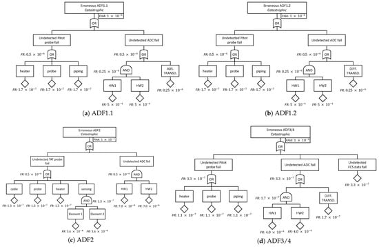
Figure 4.
Preliminary System Safety Assessment (PSSA) for air data functions.
An example is reported in Figure 4d for ADF3. In this example, from the PSSA of ADF3, it is clear that anti-icing, the Pitot probe, ducts, piping, and wiring have low FRs (about ) in order to satisfy the safety objectives derived from the FHA analysis.
Another important aspect emerged from the PSSA analysis for the worst cases of the FHA. From Figure 4d, the data from the FCS, used as input to synthetic sensors, guarantee an MTBF higher than million flight hours. This safety target can be satisfied by the A/C integrator, for instance, with a duplex or triplex redundancy of the FCS and related subsystems. The most demanding safety objectives resulting from the PSSA are collected in Table 6.
Table 6.
Failure probability requirement for the ADS components for erroneous failure conditions. The present requirements are the most severe from those obtained with Fault Tree Analysis (FTA) presented in Figure 4.
It is worth underlying that, for the particular application of the ADS, ADF2 and ADF4 are required to have the same reliability as ADF1 and ADF3. For a generic application, such as UAV and UAM, those requirements may be relaxed according to A/C integrator considerations about their failure effects.
5.3. ADS Safety Performance
Starting from Table 4, the system safety assessment (SSA) can be performed using the FTA method and the results are analysed for all ADFs.
An example of SSA is reported in Figure 5d for the synthetic function of AoA evaluation. According to the ADS parts and related MTBF, it can be noted that the unannuciated loss of ADF3 has a failure rate of , i.e., it can occur more than once over 14,500 flight hours. This result is much lower than the safety objective (one loss over 1,000,000 flight hours) reported in Table 5.
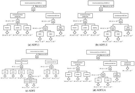
Figure 5.
System safety assessment for air data functions.
Even though it is not always applicable, all ADFs identified in this work are safety-critical. It is clear that, using both the literature MTBF and manufacturer data, the simplex ADF FRs cannot satisfy the initial safety specifications summarized in Table 7. In order to overcome this problem, two possible solutions can be adopted: (1) redesign to identify parts with higher MTBF at the ADS level and (2) adopt a redundant ADS architecture at the aircraft level.
Table 7.
SSA results of erroneous (or unannuciated) ADF failure conditions estimated starting from the MTBF of ADS sub-parts and compared with the safety objective defined in Section 2.
From Figure 5, it is clear that, for ADF1, the leading part is the Pitot probe and the most critical sub-part is the anti-icing device. For ADF2, the leading part is the TAT probe and the most critical sub-part is the anti-icing device. The MTBF of latter critical sub-parts, and for the Pitot and TAT probe, respectively, should be increased by about two orders of magnitude to achieve the safety objectives, and for the Pitot and TAT probes, respectively. As the anti-icing solutions are based on heaters, consisting basically in a resistance immersed in the probe, they have high failure rates [44]. Compliance to the indicated required MTBF target may not be realistic [46] if other solutions [47] or interchangeable heaters are not considered.
As far as the synthetic functions are concerned, as they depend on the airspeed measure or dynamic pressure from ADF, both ADF3 and ADF4 FRs are limited by the Pitot probe’s heating element.
As a side result, from s Figure 4c and Figure 5c, it can be noted that a TAT with a single sensing element for ADF2 would not satisfy the safety requirements and, under this hypothesis, the TAT sensing element becomes a safety critical sub-part along with the anti-icing.
To conclude, the most convenient way to fill the aforementioned gap in a short-term period is to adopt a redundant ADS architecture.
Redundancy is a common practice in aeronautics, where safety-critical systems are designed to have extremely improbable failure rates (e.g., less than one catastrophic event per billion hours of operation for the CS25 aircraft category). Manufacturing and installing a system that complies with the safety requirements only with a duplex or triplex redundancy is thus widely accepted. In the case of this innovative ADS device, manufacturing and installation should be pursed as, from the technological and scientific point of view, it is strategical to collect historical data on the synthetic sensors for AoA and AoS estimation.
As a final comment, according to [48], the safety requirements of ADF2 and ADF4 can be relaxed for other aircraft types such as UAVs or other specific categories and with adequate mitigation actions that could make the simplex solution meet the safety objectives for ADF2 and ADF4.
6. Conclusions
This work describes a safety analysis performed for a simplex air data system partially based on synthetic sensors that is certifiable for civil applications. As the present work is funded in the frame of Clean Sky 2, the results are related to the SAT community but they can be easily extended to any civil application and to other aircraft categories, such as UAVs and UAM vehicles. The ADS’s main innovation relies on estimation of the flow angles (angle of attack and sideslip) by means of synthetic sensors instead of classical vanes. The synthetic sensors fuse flight data available on board with deterministic algorithms based on pretrained neural networks. In order to perform a safety analysis, MTBF data of the ADS sub-parts are evaluated on a statistical basis. The safety budget is allocated to all ADFs with common FHA and PSSA, whereas the ADF reliability is evaluated using a typical SSA. The safety assessment results of the air data functions are then compared with the safety objectives. The analysis highlights that the simplex ADS solution cannot meet the airworthiness safety objectives due to technological limitations. In fact, the comparison shows that all functions of a simplex ADS have noncompliant reliability with respect to the system specifications. In particular, the air functions (AoA and AoS estimations) based on synthetic sensors cannot meet the safety objectives because they are highly dependent on airspeed measure (ADF). Overall, the most critical ADS sub-parts are identified in anti-icing devices. This limitation is not related to the present application but is related to a technological gap that can be overcome with anti-icing solutions characterizing higher MTBF or by adopting adequate ADS redundancy at the aircraft level in order to enable on-board implementation.
Author Contributions
Conceptualization, A.L.; methodology, A.L.; software, A.L.; validation, A.L. and M.B.; formal analysis, A.L.; investigation, A.L.; resources, A.L. and M.B.; data curation, A.L.; writing—original draft preparation, A.L.; writing—review and editing, A.L. and M.B.; visualization, A.L.; supervision, A.L. and M.B.; project administration, M.B.; funding acquisition, A.L. and M.B. Both authors have read and agreed to the published version of the manuscript.
Funding
The project leading to this application has received funding from the Clean Sky 2 Joint Undertaking under the European Union’s Horizon 2020 research and innovation programme under grant agreement No. 821140.
Institutional Review Board Statement
Not applicable.
Informed Consent Statement
Not applicable.
Conflicts of Interest
The authors declare no conflict of interest. The present paper reflects only the author’s view, and H2020/Clean Sky 2 is not responsible for any use that may be made of the information it contains.
Abbreviations
The following abbreviations are used in this manuscript:
| A/C | Aircraft |
| AHRS | Attitude and Heading Reference System |
| ADC | Air Data Computer |
| ADF | Air Data Function |
| ADS | Air Data System |
| AoA | Angle-of-Attack |
| AoS | Angle-of-Sideslip |
| CAS | Calibrated Airspeed |
| CS | Certification Specifications |
| FBW | Fly-by-Wire |
| FCC | Flight Control Computer |
| FCS | Flight Control System |
| FHA | Failure Hazard Analysis |
| FMEA | Failure Modes and Effect Analysis |
| FPGA | Field Programmable Gate Array |
| FR | Failure Rate |
| FTA | Fault Tree Analysis |
| GNSS | Global Navigation Satellite System |
| HW | Hardware |
| I/O | Input/Output |
| LAND | Landing phase |
| LRU | Line Replaceable Unit |
| MCC | Most Critical Conditions |
| MLP | Multilayer Perceptron |
| MTBF | Mean Time Between Failures |
| OAT | Outside Air Temperature |
| PF | Probability of Failure occurrence |
| PSSA | Preliminary System Safety Assessment |
| SAT | Small Air Transport |
| SSA | System Safety Assessment |
| T/O | Takeoff phase |
| TAS | True Airspeed |
| TAT | Total Air Temperature |
| UAM | Urban Air Mobility |
| UAV | Unmanned Aerial Vehicles |
| SEU | Single Event Upset |
| SS | Virtual, Analytical or Synthetic Sensor |
Appendix A. FHA Tables
The FHA reference ID is composed of “function name”, “type of failure”, and “incremental letter” (to identify a combination of failure condition and flight phase). For type of failure, only the function loss is considered (using the code 1), whereas all other malfunctions are out of the scope of the present work.
Table A1.
ADS FHA for ADF.
Table A1.
ADS FHA for ADF.
| Function (FHA Ref.) | Failure Condition (Hazard Description) | Flight Phase | Effect of Failure Condition on Aircraft/Crew | Classification | Remarks/Mitigation |
|---|---|---|---|---|---|
| Static pressure | Total loss of the capability to measure the static pressure. Possible failure of the static pressure holes, heater elements, or ADC. | All phases | No speed, altitude, pressure error correction, TAT calibration, synthetic information. Limited flight envelope. Mission may be aborted, A/C may be lost. Erroneous measure of the static pressure undetectable at ADS level. | see below | |
| ADF-1.a | a. Unannuciated loss | in-flight | Piloted: Crew is not able to control/pilot the A/C correctly. Mission may be aborted or A/C may be lost. AutoPilot: AP is unable to control/pilot the A/C correctly. If the crew does not disengage the AP, A/C may be lost. | Catastrophic | |
| ADF-1.b | b. Annunciated loss | in-flight | Crew can detect the failed information to exclude them. Crew is not able to control/pilot the A/C correctly. Mission may be aborted or A/C may be lost. | Hazardous | |
| ADF-1.c | c. Unannuciated loss | T/O in-flight | See ADF-1.a | Catastrophic | |
| ADF-1.d | d. Annunciated loss | T/O in-flight | Crew cannot abort the takeoff. Crew is not able to control/pilot the A/C correctly. Mission may be aborted or A/C may be lost. | Hazardous | Crew can rely on other systems to land immediately |
| ADF-1.e | e. Unannuciated loss | T/O ground | Crew will continue the takeoff. Crew is not able to control/pilot the A/C correctly. Mission may be aborted or A/C may be lost. | Catastrophic | |
| ADF-1.f | f. Annunciated loss | T/O ground | Crew is able to abort the takeoff or control/pilot the A/C correctly on ground. Takeoff can be safely aborted. | No safety effect | |
| ADF-1.g | g. Unannuciated loss | LAND in-flight | See ADF-1.a | Catastrophic | |
| ADF-1.h | h. Annunciated loss | LAND in-flight | Crew is not able to control/pilot the A/C correctly. Mission may be aborted or A/C may be lost. | Hazardous | Crew can rely on other systems to land. |
| ADF-1.i | i. Unannuciated loss | LAND ground | Crew is able to control/pilot the A/C correctly on ground. Landing can be safely completed to a full stop position. | No safety effect | |
| ADF-1.j | j. Annunciated loss | LAND ground | Crew is able to control/pilot the A/C correctly on ground. Landing can be safely completed to a full stop position. | No safety effect |
Table A2.
ADS FHA for ADF.
Table A2.
ADS FHA for ADF.
| Function (FHA Ref.) | Failure Condition (Hazard Description) | Flight Phase | Effect of Failure Condition on Aircraft/Crew | Classification | Remarks/Mitigation |
|---|---|---|---|---|---|
| Dynamic pressure | Total loss of the capability to measure the dynamic pressure. Possible failure of the static pressure hole, the total tube, heater elements or ADC. | All phases | No speed, pressure error correction, TAT calibration, synthetic information. Limited flight envelope, mission may be aborted or A/C may be lost. Erroneous measure of the static pressure undetectable at ADS level. | see below | |
| ADF-1.a | a. Unannuciated loss | in-flight | Piloted: Crew is not able to control/pilot the A/C correctly. Mission may be aborted or A/C may be lost. AutoPilot: AP is unable to control/pilot the A/C correctly. If the crew does not disengage the AP, A/C may be lost. | Catastrophic | |
| ADF-1.b | b. Annunciated loss | in-flight | Crew can detect the failed information to exclude them. Crew is not able to control/pilot the A/C correctly. Mission may be aborted or A/C may be lost. | Hazardous | |
| ADF-1.c | c. Unannuciated loss | T/O in-flight | See ADF-1.a | Catastrophic | |
| ADF-1.d | d. Annunciated loss | T/O in-flight | Crew cannot abort the takeoff. Crew is not able to control/pilot the A/C correctly. Mission may be aborted or A/C may be lost. | Hazardous | Crew can rely on other systems to land immediately |
| ADF-1.e | e. Unannuciated loss | T/O ground | Crew will continue the takeoff. Crew is not able to control/pilot the A/C correctly. Mission may be aborted or A/C may be lost. | Catastrophic | |
| ADF-1.f | f. Annunciated loss | T/O ground | Crew is able to abort the takeoff or control/pilot the A/C correctly on ground. Takeoff can be safely aborted. | No safety effect | |
| ADF-1.g | g. Unannuciated loss | LAND in-flight | See ADF-1.a | Catastrophic | |
| ADF-1.h | h. Annunciated loss | LAND in-flight | Crew is not able to control/pilot the A/C correctly. Mission may be aborted or A/C may be lost. | Hazardous | Crew can rely on other systems to land. |
| ADF-1.i | i. Unannuciated loss | LAND ground | Crew is able to control/pilot the A/C correctly on ground. Landing can be safely completed to a full stop position. | No safety effect | |
| ADF-1.j | j. Annunciated loss | LAND ground | Crew is able to control/pilot the A/C correctly on ground. Landing can be safely completed to a full stop position. | No safety effect |
Table A3.
ADS FHA for ADF2.
Table A3.
ADS FHA for ADF2.
| Function (FHA Ref.) | Failure Condition (Hazard Description) | Flight Phase | Effect of Failure Condition on Aircraft/Crew | Classification | Remarks/Mitigation |
|---|---|---|---|---|---|
| Total air temperature | Total loss of the capability to measure the total air temperature. Possible failure of the TAT probes, heater elements, sensing elements or ADC. | All phases | No TAS, density information. Limited flight envelope, mission may be aborted. | see below | |
| ADF2-1.a | a. Unannuciated loss | in-flight | Piloted: Crew has wrong information on speed protections and density altitudes. Mission may be aborted. AutoPilot: AP may be unable to control/pilot the A/C correctly. If the crew does not disengage the AP, A/C may be lost. | Catastrophic | Hazardous/Major if TAS or temperature are not used by safety critical systems or AP is not engaged. |
| ADF2-1.b | b. Annunciated loss | in-flight | Crew can detect the failed information to exclude them. Crew is able to control/pilot the A/C correctly. Limited flight envelope or mission may be aborted. | Hazardous | |
| ADF2-1.c | c. Unannuciated loss | T/O in-flight | See ADF.a | Catastrophic | See ADF.a |
| ADF2-1.d | d. Annunciated loss | T/O in-flight | See ADF.b | Hazardous | |
| ADF2-1.e | e. Unannuciated loss | T/O ground | Crew will continue the takeoff. Crew has wrong information on speed protections and density altitudes. Mission may be aborted or A/C may be lost. | Catastrophic | Hazardous/Major if TAS or temperature are not used by safety critical systems or AP is not engaged. |
| ADF2-1.f | f. Annunciated loss | T/O ground | Crew is able to abort the takeoff or control/pilot the A/C correctly on ground. Takeoff and mission can be safely aborted. | No safety effect | |
| ADF2-1.g | g. Unannuciated loss | LAND in-flight | Crew has wrong information on speed protections and density altitudes that may be not crucial to conclude the landing phase. Landing can be completed. | Hazardous | |
| ADF2-1.h | h. Annunciated loss | LAND in-flight | Crew can detect the failed information to exclude them. Land can be completed. | Minor | |
| ADF2-1.i | i. Unannuciated loss | LAND ground | Crew is able to control/pilot the A/C correctly on ground. Landing can be safely completed to a full stop position. | No safety effect | |
| ADF2-1.j | j. Annunciated loss | LAND ground | Crew is able to control/pilot the A/C correctly on ground. Landing can be safely completed to a full stop position. | No safety effect |
Table A4.
ADS FHA for ADF3.
Table A4.
ADS FHA for ADF3.
| Function (FHA Ref.) | Failure Condition (Hazard Description) | Flight Phase | Effect of Failure Condition on Aircraft/Crew | Classification | Remarks/Mitigation |
|---|---|---|---|---|---|
| Angle of attack | Total loss of capability to measure AoA. Possible system fail: ADF1 (static or dynamic pressure functions), ADC or input from the FCC | All phases | No AoA Limited flight envelop Mission may be aborted A/C may be lost | see below | |
| ADF3-1.a | a. Unannuciated loss | in-flight | Piloted: Crew has wrong information on stall protection disagreeing with speed indications. Crew may be not able to control/pilot the A/C correctly. Mission may be aborted or A/C may be lost. AutoPilot: AP is unable to control/pilot the A/C correctly. If the crew does not disengage the AP, A/C may be lost. | Catastrophic | Hazardous if piloted, or AP is not engaged |
| ADF3-1.b | b. Annunciated loss | in-flight | Crew can detect the failed information to exclude them. Limiting the flight envelope, crew may be able to control/pilot the A/C correctly. Mission may be aborted. | Hazardous | |
| ADF3-1.c | c. Unannuciated loss | T/O in-flight | See ADF3-1.a | Catastrophic | Hazardous if piloted, or AP is not engaged |
| ADF3-1.d | d. Annunciated loss | T/O in-flight | See ADF3-1.b | Hazardous | |
| ADF3-1.e | e. Unannuciated loss | T/O ground | Crew will continue the takeoff. Crew has wrong information on stall protection disagreeing with the speed indication. Mission may be aborted or A/C may be lost. | Catastrophic | |
| ADF3-1.f | f. Annunciated loss | T/O ground | Crew is able to abort the takeoff or control/pilot the A/C correctly on ground. Takeoff and mission can be safely aborted. | No safety effect | |
| ADF3-1.g | g. Unannuciated loss | LAND in-flight | Crew has wrong information on stall protection disagreeing with speed indications. Mission may be aborted or A/C may be lost. | Catastrophic | Hazardous if piloted, or AP is not engaged |
| ADF3-1.h | h. Annunciated loss | LAND in-flight | See ADF3-1.b | Major | |
| ADF3-1.i | i. Unannuciated loss | LAND ground | Crew is able to control/pilot the A/C correctly on ground. Landing can be safely completed to a full stop position. | No safety effect | |
| ADF3-1.j | j. Annunciated loss | LAND ground | Crew is able to control/pilot the A/C correctly on ground. Landing can be safely completed to a full stop position. | No safety effect |
Table A5.
ADS FHA for ADF4.
Table A5.
ADS FHA for ADF4.
| Function (FHA Ref.) | Failure Condition (Hazard Description) | Flight phase | Effect of Failure Condition on Aircraft/Crew | Classification | Remarks/mitigation |
|---|---|---|---|---|---|
| Angle of sideslip | Total loss of capability to measure AoA. Possible system fail: ADF1 (static or dynamic pressure functions), ADC or input from the FCC | All phases | No angle of sideslip information. Limited flight envelope, mission may be aborted or A/C may be lost | see below | |
| ADF4-1.a | a. Unannuciated loss | in-flight | Autopilot can be affected. Crew may be not able to recover the A/C correctly. Mission may be aborted or A/C may be lost. | Catastrophic | Major/Minor if AoS is not used by safety critical systems or AP is not engaged. |
| ADF4-1.b | b. Annunciated loss | in-flight | Autopilot can be disengaged. Crew is able to recover the A/C and to control/pilot the A/C correctly. Mission may be aborted. | Hazardous | This is a system specification by the aircraft integrator [30] |
| ADF4-1.c | c. Unannuciated loss | T/O in-flight | See ADF4-1.a | Catastrophic | Major/Minor if AoS is not used by safety critical systems or AP is not engaged. |
| ADF4-1.d | d. Annunciated loss | T/O in-flight | See ADF4-1.b | Hazardous | See ADF4-1.b |
| ADF4-1.e | e. Unannuciated loss | T/O ground | Autopilot can be affected. Crew will continue the takeoff and may be not able to recover the A/C correctly. Mission may be aborted or A/C may be lost. | Catastrophic | |
| ADF4-1.f | f. Annunciated loss | T/O ground | Crew is able to abort the takeoff or control/pilot the A/C correctly on ground. Takeoff and mission can be safely aborted. | No safety effect | |
| ADF4-1.g | g. Unannuciated loss | LAND in-flight | Autopilot can be affected. Crew may be not able to recover the A/C correctly. Mission may be aborted or A/C may be lost. | Catastrophic | Hazardous if piloted, or AP is not engaged |
| ADF4-1.h | h. Annunciated loss | LAND in-flight | Autopilot can be disengaged. Crew may be able to recover the A/C and to control/pilot the A/C correctly. | Minor | |
| ADF4-1.i | i. Unannuciated loss | LAND ground | Crew is able to control/pilot the A/C correctly on ground. Landing can be safely completed to a full stop position. | No safety effect | |
| ADF4-1.j | j. Annunciated loss | LAND ground | Crew is able to control/pilot the A/C correctly on ground. Landing can be safely completed to a full stop position. | No safety effect |
References
- European Aviation Safety Agency, EASA. Certification Specifications for Normal Utility, Aerobatic, and Commuter Category Aeroplanes—CS23; European Aviation Safety Agency, EASA: Cologne, Germany, 2012.
- Lerro, A.; Battipede, M.; Gili, P.; Ferlauto, M.; Brandl, A.; Merlone, A.; Musacchio, C.; Sangaletti, G.; Russo, G. The Clean Sky 2 MIDAS Project—An Innovative Modular, Digital and Integrated Air Data System for Fly-by-Wire Applications. In Proceedings of the 2019 IEEE 5th International Workshop on Metrology for AeroSpace (MetroAeroSpace), Torino, Italy, 19–21 June 2019; pp. 714–719. [Google Scholar] [CrossRef]
- SAE International. Guidelines for Development of Civil Aircraft and Systems; SAE International: London, UK, 2010. [Google Scholar] [CrossRef]
- European Aviation Safety Agency, EASA. Certification Specifications and Acceptable Means of Compliance for Large Aeroplanes CS-25, Amendment 16; European Aviation Safety Agency, EASA: Cologne, Germany, 2015.
- SAE International. Air Data Computer: Minimum Performance Standard, Aerospace Standard; SAE International: London, UK, 1996. [Google Scholar]
- Rhudy, M.B.; Larrabee, T.; Chao, H.; Gu, Y.; Napolitano, M. UAV Attitude, Heading, and Wind Estimation Using GPS/INS and an Air Data System. In Proceedings of the AIAA Guidance, Navigation, and Control (GNC) Conference, Boston, MA, USA, 19–22 August 2013; American Institute of Aeronautics and Astronautics: Reston, VA, USA, 2013; pp. 1–11. [Google Scholar] [CrossRef]
- Colgren, R.; Frye, M.; Olson, W. A proposed system architecture for estimation of angle-of-attack and sideslip angle. In Proceedings of the Guidance, Navigation, and Control Conference and Exhibit, Portland, OR, USA, 9–11 August 1999; American Institute of Aeronautics and Astronautics: Reston, VA, USA, 1999; pp. 743–750. [Google Scholar] [CrossRef]
- Lie, F.A.P.; Gebre-Egziabher, D. Sensitivity Analysis of Model-based Synthetic Air Data Estimators. In Proceedings of the AIAA Guidance, Navigation, and Control Conference, Kissimmee, FL, USA, 5–9 January; American Institute of Aeronautics and Astronautics: Reston, VA, USA, 2015; pp. 1–18. [Google Scholar] [CrossRef]
- Gertler, J. Analytical Redundancy Methods in Fault Detection and Isolation-Survey and Synthesis. In Proceedings of the IFAC/IMACS Symposium on Fault Detection, Supervision and Safety for Technical Processes (SAFEPROCESS’91), Baden-Baden, Germany, 10–13 September 1991. [Google Scholar] [CrossRef]
- Oosterom, M.; Babuska, R. Virtual Sensor for the Angle-of-Attack Signal in Small Commercial Aircraft. In Proceedings of the 2006 IEEE International Conference on Fuzzy Systems, Vancouver, BC, Canada, 16–21 July 2006; pp. 1396–1403. [Google Scholar] [CrossRef]
- Samara, P.A.; Fouskitakis, G.N.; Sakellariou, J.S.; Fassois, S.D. Aircraft angle-of-attack virtual sensor design via a functional pooling narx methodology. In Proceedings of the 2003 European Control Conference (ECC), Cambridge, UK, 1–4 September 2003; pp. 1816–1821. [Google Scholar] [CrossRef]
- Perhinschi, M.; Campa, G.; Napolitano, M.; Lando, M.; Massotti, L.; Fravolini, M. Modelling and Simulation of a Fault-Tolerant Flight Control System. Int. J. Model. Simul. 2006, 26, 1–10. [Google Scholar] [CrossRef]
- Pouliezos, A.D.; Stavrakakis, G.S. Analytical Redundancy Methods. In Real Time Fault Monitoring of Industrial Processes; Springer: Dordrecht, The Netherlands, 1994; Volume 12, pp. 93–178. [Google Scholar] [CrossRef]
- Rhudy, M.B.; Fravolini, M.L.; Porcacchia, M.; Napolitano, M.R. Comparison of wind speed models within a Pitot-free airspeed estimation algorithm using light aviation data. Aerosp. Sci. Technol. 2019, 86, 21–29. [Google Scholar] [CrossRef]
- Balzano, F.; Fravolini, M.; Napolitano, M.R.; d’Urso, S.; Crispoltoni, M.; del Core, G. Air Data Sensor Fault Detection with an Augmented Floating Limiter. Int. J. Aerosp. Eng. 2018, 2018, 1–16. [Google Scholar] [CrossRef]
- Eubank, R.; Atkins, E.; Ogura, S. Fault Detection and Fail-Safe Operation with a Multiple-Redundancy Air-Data System. In Proceedings of the AIAA Guidance, Navigation, and Control Conference, Toronto, ON, Canada, 2–5 August 2010; American Institute of Aeronautics and Astronautics: Reston, VA, USA, 2010; pp. 1–14. [Google Scholar] [CrossRef]
- Lu, P.; Van Eykeren, L.; Van Kampen, E.J.; Chu, Q. Air Data Sensor Fault Detection and Diagnosis with Application to Real Flight Data. In Proceedings of the AIAA Guidance, Navigation, and Control Conference, AIAA SciTech Forum, (AIAA 2015-1311), Kissimmee, FL, USA, 5–9 January 2015; pp. 1–18. [Google Scholar] [CrossRef]
- Dendy, J.; Transier, K. Angle-of-Attack Computation Study; Technical report; AFFDL-TR-69-93; Air Force Flight Dynamics Laboratory: Wright-Patterson Air Force Base, OH, USA, 1969. [Google Scholar]
- Freeman, D.B. Angle of Attack Computation System; Technical report; AFFDL-TR-73-89; Air Force Flight Dynamics Laboratory: Wright-Patterson Air Force Base, OH, USA, 1973. [Google Scholar]
- Rohloff, T.J.; Whitmore, S.A.; Catton, I. Air data sensing from surface pressure measurements using a neural network method. AIAA J. 1998, 36, 2094–2101. [Google Scholar] [CrossRef]
- Wise, K.A. Computational Air Data System for Angle-of-Attack and Angle-of-Sideslip. U.S. Patent 6,928,341 B2, 9 August 2005. [Google Scholar]
- Langelaan, J.W.; Alley, N.; Neidhoefer, J. Wind Field Estimation for Small Unmanned Aerial Vehicles. J. Guid. Control Dyn. 2011, 34, 1016–1030. [Google Scholar] [CrossRef]
- Lu, P.; Van Eykeren, L.; van Kampen, E.; de Visser, C.C.; Chu, Q.P. Adaptive Three-Step Kalman Filter for Air Data Sensor Fault Detection and Diagnosis. J. Guid. Control Dyn. 2016, 39, 590–604. [Google Scholar] [CrossRef]
- Prem, S.; Sankaralingam, L.; Ramprasadh, C. Pseudomeasurement-Aided Estimation of Angle of Attack in Mini Unmanned Aerial Vehicle. J. Aerosp. Inf. Syst. 2020, 1–12. [Google Scholar] [CrossRef]
- Valasek, J.; Harris, J.; Pruchnicki, S.; McCrink, M.; Gregory, J.; Sizoo, D.G. Derived Angle of Attack and Sideslip Angle Characterization for General Aviation. J. Guid. Control Dyn. 2020, 43, 1039–1055. [Google Scholar] [CrossRef]
- Sun, K.; Regan, C.D.; Egziabher, D.G. GNSS/INS based estimation of air data and wind vector using flight maneuvers. In Proceedings of the 2018 IEEE/ION Position, Location and Navigation Symposium (PLANS), Monterey, CA, USA, 23–26 April 2018; pp. 838–849. [Google Scholar] [CrossRef]
- Lerro, A.; Brandl, A.; Gili, P. Model-Free Scheme for Angle-of-Attack and Angle-of-Sideslip Estimation. J. Guid. Control. Dyn. 2021, 44, 595–600. [Google Scholar] [CrossRef]
- Lerro, A.; Brandl, A.; Battipede, M.; Gili, P. Preliminary Design of a Model-Free Synthetic Sensor for Aerodynamic Angle Estimation for Commercial Aviation. Sensors 2019, 19, 5133. [Google Scholar] [CrossRef]
- Lando, M.; Battipede, M.; Gili, P.A. Neuro-Fuzzy Techniques for the Air-Data Sensor Calibration. J. Aircr. 2007, 44, 945–953. [Google Scholar] [CrossRef]
- Piaggio Aerospace. Air Data Probe Specification—Clean Sky 2 WP7.3—Deliverable D7,3,4-1; Piaggio Aerospace: Villanova d’Albenga, Italy, 2018. [Google Scholar]
- SAE International. Guidelines and Methods for Conducting the Safety Assessment Process on Civil Airborne Systems and Equipment; SAE International: London, UK, 1996. [Google Scholar] [CrossRef]
- Hull, D.G. Fundamentals of Airplane Flight Mechanics, 1st ed.; Springer Publishing Company, Incorporated: Berlin/Heidelberg, Germany, 2007. [Google Scholar]
- Lerro, A.; Battipede, M.; Sangaletti, G.; Barbera, D.; Antinori, S. Safety Assessment for Certified Air Data Systems based on Synthetic Sensors. In Proceedings of the 2020 IEEE 7th International Workshop on Metrology for AeroSpace (MetroAeroSpace), Pisa, Italy, 22–24 June 2020; pp. 193–198. [Google Scholar] [CrossRef]
- Lerro, A.; Battipede, M.; Gili, P.; Brandl, A. Aerodynamic angle estimation: Comparison between numerical results and operative environment data. CEAS Aeronaut. J. 2019. [Google Scholar] [CrossRef]
- Lerro, A.; Brandl, A.; Battipede, M.; Gili, P. A Data-Driven Approach to Identify Flight Test Data Suitable to Design Angle of Attack Synthetic Sensor for Flight Control Systems. Aerospace 2020, 7, 63. [Google Scholar] [CrossRef]
- Cybenko, G. Approximation by superpositions of a sigmoidal function. Math. Control Signals Syst. 1989, 2, 303–314. [Google Scholar] [CrossRef]
- Lerro, A.; Battipede, M.; Gili, P. System and Process for Measuring and Evaluating Air and Inertial Data. EP3022565A2, 16 July 2013. [Google Scholar]
- Bishop, C.M. Neural Networks for Pattern Recognition; Clarendon Press Oxford: Oxford, UK, 1995. [Google Scholar]
- Castro, J.; Mantas, C.; Benítez, J. Neural networks with a continuous squashing function in the output are universal approximators. Neural Netw. 2000, 13, 561–563. [Google Scholar] [CrossRef]
- Attali, J.G.; Pagès, G. Approximations of Functions by a Multilayer Perceptron: A New Approach. Neural Netw. 1997, 10, 1069–1081. [Google Scholar] [CrossRef]
- Hornik, K. Approximation capabilities of multilayer feedforward networks. Neural Netw. 1991, 4, 251–257. [Google Scholar] [CrossRef]
- Haykin, S. Neural Networks: A Comprehensive Foundation; Prentice Hall PTR: Upper New Jersey River, NJ, USA, 1994. [Google Scholar]
- SAE International. Minimum Performance Standard Angle of Attack Equipment; SAE International: London, UK, 1992. [Google Scholar]
- Quanterion Solutions Incorporated. Quanterion Nonelectronic Parts Reliability Data—2016; Reliability Databook Series; Quanterion Solutions Incorporated: Utica, NY, USA, 2016. [Google Scholar]
- MIDAS Consortium. MIDAS Preliminary Design Review; MIDAS Consortium: Coleraine, UK, 2019. [Google Scholar]
- Lerro, A. Survey of Certifiable Air Data Systems for Urban Air Mobility. In Proceedings of the 2020 AIAA/IEEE 39th Digital Avionics Systems Conference (DASC), San Antonio, TX, USA, 11–15 October 2020; pp. 1–10. [Google Scholar] [CrossRef]
- Bai, T.; Zhu, C.; Miao, B.; Li, K.; Zhu, C. Vibration de-icing method with piezoelectric actuators. J. Vibroeng. 2015, 17, 61–73. [Google Scholar]
- European Aviation Safety Agency, EASA. Easy Access Rules for Unmanned Aircraft Systems; European Aviation Safety Agency, EASA: Cologne, Germany, 2015.
Publisher’s Note: MDPI stays neutral with regard to jurisdictional claims in published maps and institutional affiliations. |
© 2021 by the authors. Licensee MDPI, Basel, Switzerland. This article is an open access article distributed under the terms and conditions of the Creative Commons Attribution (CC BY) license (http://creativecommons.org/licenses/by/4.0/).