Article

Towards an Occupancy-Oriented Digital Twin for Facility Management: Test Campaign and Sensors Assessment

by
Elena Seghezzi
1,*,
Mirko Locatelli
1,
Laura Pellegrini
1,
Giulia Pattini
1,
Giuseppe Martino Di Giuda
2,
Lavinia Chiara Tagliabue
3 and
Guido Boella
3
1
Department of Architecture, Built Environment and Construction Engineering, Politecnico di Milano, via Ponzio 31, 20133 Milan, Italy
2
Department of Management, Università Degli Studi di Torino, Via Verdi 8, 10124 Turin, Italy
3
Department of Computer Science, Università Degli Studi di Torino, Corso Svizzera 185, 10124 Turin, Italy
*
Author to whom correspondence should be addressed.
Appl. Sci. 2021, 11(7), 3108; https://doi.org/10.3390/app11073108
Submission received: 28 February 2021 / Revised: 15 March 2021 / Accepted: 23 March 2021 / Published: 31 March 2021
(This article belongs to the Special Issue Cognitive Buildings)

Abstract

:
This study focuses on calibration and test campaigns of an IoT camera-based sensor system to monitor occupancy, as part of an ongoing research project aiming at defining a Building Management System (BMS) for facility management based on an occupancy-oriented Digital Twin (DT). The research project aims to facilitate the optimization of building operational stage through advanced monitoring techniques and data analytics. The quality of collected data, which are the input for analyses and simulations on the DT virtual entity, is critical to ensure the quality of the results. Therefore, calibration and test campaigns are essential to ensure data quality and efficiency of the IoT sensor system. The paper describes the general methodology for the BMS definition, and method and results of first stages of the research. The preliminary analyses included Indicative Post-Occupancy Evaluations (POEs) supported by Building Information Modelling (BIM) to optimize sensor system planning. Test campaign are then performed to evaluate collected data quality and system efficiency. The method was applied on a Department of Politecnico di Milano. The period of the year in which tests are performed was critical for lighting conditions. In addition, spaces’ geometric features and user behavior caused major issues and faults in the system.Incorrect boundary definition: areas that are not covered by boundaries; thus, they are not monitored

1. Introduction

The operation and maintenance (O&M) phase of buildings and civil infrastructures ranges between 20–30 years for buildings, but it can cover more than 50 years of the whole lifecycle [1]. It is essential to ensure an actual and efficient management of buildings during the O&M phase. Occupancy and actual use of spaces strongly affect the organizational effectiveness and functioning during the operational phase [2,3]. Typically, standardized and fixed values of occupancy are considered during design phases, e.g., maximum occupancy values from fire regulations or scheduled occupancy for energy models [4]. Consequently, actual occupancy and space use levels may significantly vary from and rarely correspond to the values considered during the design phase. Occupancy strongly influences use and cleanness of spaces, which in turn are related to well-being, satisfaction, and productivity of users [5,6]. In recent years, a consistent number of studies investigated the segment of the performance gap between expected energy consumptions, defined during the design phase, and actual consumptions, due to human-building interaction and variable occupancy [6,7,8,9,10,11,12,13,14,15,16,17]. However, other promising fields in building management include security, safety, cleanness, and space management. These aspects can have a crucial role, especially in light of current sanitary emergencies related to the spread of the COVID-19 pandemic: space monitoring is a key aspect to guarantee safety in existing buildings [18].
In this context, the aim of the ongoing research project here presented is to define a Building Management Systems (BMS) based on an occupancy-oriented Digital Twin (DT), evolving from and enriching the Building Information Model (BIM) and integrating occupancy levels and additional relevant data from Post-Occupancy Evaluations (POEs). Analyses and simulations of the occupancy-oriented DT would support the decision-making processes during the O&M phase.
The case study for the application of the methodology is an existing office building hosting the Department of Architecture, built environment, and construction engineering (DABC) at Politecnico di Milano, Italy, used by people working at the university and performing their research and administrative activities in the indoor spaces of the building. The maintenance and cleanness of the distribution spaces and offices is a very important aspect in the facility management of the building and department business plan; strong variations in occupants’ flows are experienced by the users and particularly during the pandemic.
The IoT network of sensors that represents the source of data for the occupancy-oriented DT and that was tested and calibrated as described in this article was provided and installed by an external consulting company (Laser Navigation srl). They provided the hardware part of the system that is the camera-based sensors with an embedded deep learning algorithm, the installation, and the technical settings of the sensors. They also provided an online platform named SophyAI and integrated with the IoT system, that allows to visualize, store, and download collected data.
This paper focuses on the preparatory phases for the definition of the DT, i.e., sensor system calibration and collected data quality validation. In fact, a fundamental characteristic of a DT is the connection, alignment, and reciprocity between the physical and virtual part [19]. Therefore, a key aspect is the data collection process, ensuring data quality on which the correct digital representation of the physical phenomenon depends [20,21], since, in order to obtain satisfactory results, is essential to ensure the quality of input data [22]. In this perspective, fundamental steps are the selection of sensor types that are most suitable for the specific application [23], the spatial distribution of sensors in the indoor spaces [24], and the setting and calibration of the IoT sensor system [25,26], to allow a correct detection and collection of data.
Given the importance of data quality for the proper digital representation of the building occupancy phenomenon, the objectives of the research are: optimization of spatial distribution and orientation of sensors for system planning and installation, identification of issues and faults of the detection system, and resolution of issues and faults by performing an assessment of the detection system through test campaigns. This study proposes method and evaluation criteria for system calibration and data quality validation, also defining parameters for occupancy analysis. Two test campaigns were performed until all major faults have been checked and solved, allowing for the verification and validation of collected data quality to monitor building occupancy. The study also describes and tests the use of the platform SophyAI for real-time visualization of data during the test campaigns.

2. Literature Review

2.1. Evolution, Main Applications, and Features of Post-Occupancy Evaluations

Post-Occupancy Evaluations (POEs) aim at assessing building performances, users’ behavior, and feedback regarding existing buildings during the operational phase and once the building has been occupied for some time [27,28,29,30,31]. POEs were first introduced in the UK and US in the 1960s in order to assess building performances from user perspective, by means of interviews, questionnaires, photographic surveys, and walk-through surveys [27,28]. The major developments of POEs were during the 1980s, aiming at analyzing and optimizing the facility management and design [29]. POEs had been performed in the US, mainly in the public sector, UK, New Zealand, and Canada [32], and, since a correlation between workplace features and worker productivity was proposed in 1985, they have been also applied in the private sector to improve costumer and worker satisfaction and to optimize the workplaces [30]. In the mid-90s, the interest moved from analyses during the operational phase alone to an entire building life cycle process, i.e., Building Performance Evaluation (BPE) [33,34]. Insights and findings from POEs could be applied in the subsequent design and building life cycle process [34,35,36].
In the last two decades, POEs have mainly been applied to assess and optimize building energy performances, and to reduce the building environmental impacts [37]. A less investigated but promising research field is the optimization of occupancy patterns, and cleaning activities and contracts. Space features and workplace cleanness have been classified as basic factors affecting user satisfaction [5], and, consequently, user productivity. The variable “interior use of space” can account for around 43% of the variance in employees’ enjoyment at work, well-being, and perceived productivity [6].
As above mentioned, POEs are analyses of the built environment, aiming at defining the effectiveness and functionality of spaces for users, building performances, and user satisfaction and perception regarding facilities in general and workplaces in particular [27,38]. There are three levels of POEs depending on accuracy, time needed to be performed, tools, and levels of invasiveness of user privacy [7,30]:
  • Indicative POEs enable to perform overall non-invasive analyses of the building, with selected interviews and photographic surveys to detect critical areas of the building.
  • Investigative POEs are more in-depth analyses, and more invasive, with questionnaires, video recordings, and measurement, and they are meant to find causes and consequences of the building performances.
  • Diagnostic POEs are the most in-depth analyses, with high levels of user privacy invasiveness and high costs, since they can imply the use of sensor systems to monitor the building, providing data to analyze and optimize building performances and future designs.
Despite being expensive and invasive for user privacy, especially when performing diagnostic analyses, POEs can have several benefits, ranging from the optimization of the operational phase in terms of performances and user satisfaction, to an increased facility adaptation to organizational change and growth over time [27,30], and to the definition of design criteria and requirements based on actual user and space needs for similar buildings [39].

2.2. From Building Information Models to Digital Twins for Asset Management

In recent years, a major evolution of Building Information Modelling (BIM) occurred in the construction sector. BIM models are parametric models, centralized sources of information mostly for the design and construction phases, and instruments to improve collaboration among specialists and document management [40]. The application of BIM for facility management can result in several benefits: customer services improvement, time and cost reduction resulting from better planning capabilities, and higher consistency of data [41,42]. The integration of POEs in a BIM approach enables the connection between POE data and the digital model [8,12,43], with the advantages of defining a single source and storage of POE and building data, integrating structured data into the BIM, and identifying POE data and related issues in a visual representation of the building space [8,44,45]. Despite the advantages of adopting BIM during the operational phase, a BIM approach for asset management lacks of information richness, analysis, and simulation capability, which are usually manually implemented and time-consuming when using a BIM model [20]. In addition, an effective and efficient management of buildings during the operational phase strongly rely on continuous flows of real time data regarding the building, its performances, and conditions [20,46]. However, BIM models present limitations for the integration with different data sources and systems, e.g., sensor data, and lack of automatic updating and evolution over time [20]. Therefore, in order to overcome these limitations, the definition of a Digital Twin is investigated.

2.3. Evolution of the Digital Twin Concept

The Digital Twin (DT) concept dates back in 2002 when the idea of a virtual space containing the information of and linked to the real space emerged in the field of study of complex systems, in particular regarding the Product Lifecycle Management (PLM) [19]. When the concept emerged, it was not referred to as DT, but it was presented as the “Conceptual Ideal for PLM” [19], evolved then to Mirrored Spaces Model in 2005 [47] and to Information Mirroring Model in 2006 [48] and 2011, when also the term Digital Twin was first used to describe the model [49]. In recent years, the concept of a DT has been studied also in the aerospace sector: the DT represents an ultra-realistic digital replica of real flying vehicles, considering one or more interconnected systems allowing for probabilistic simulations that take into account physical characteristics and models, sensor data, and history of previous flights and vehicles [50,51,52]. Recent definitions of DTs can be found in various sectors, with a wide use and diffusion of the concept of a virtual replica of physical entities whose purpose is to manage, optimize, and control the physical asset itself. In the infrastructure sector, DT was defined as a realistic virtual representation of the corresponding infrastructure, adding the built or natural context in which the object is contained and to which it is connected [53]. In the manufacturing sector, the idea of the connection between physical components and virtual models is widened, adding the necessary mono- or bi-directional flow of data between the physical asset and its virtual counterpart in order to real-time monitoring the actual object, supporting simulations, analytics, and control capabilities of the dynamic virtual model [54]. The construction industry can be still considered in its beginning regarding the definition of a DT for buildings. Despite the various attempts to define a DT in construction industry [21,24,53,55,56], a comprehensive definition was proposed by Al-Sehrawy and Kumar [57]: “an approach for connecting a physical system to its virtual representation via bidirectional communication (with or without human in the loop) using temporally updated Big Data […] to allow for exploitation of Artificial Intelligence and Big Data Analytics by harnessing this data to unlock value through optimization and prediction of future state”. This definition includes all the fundamental parts of a DT, which are described in detail in the following paragraph.

2.4. Elements and Characteristics of a Digital Twin

As stated, a DT is composed by some elements. A list of components for DTs in construction industry is provided as follows:
  • A physical asset and its virtual counterpart, and data connecting them [23];
  • Platform to visualize and manage sensor data, e.g., data and virtual model visualization, analysis, and simulation, which is a key aspect for real-time remote monitoring [23]. The platform should return insights, alerts, or predictions regarding the physical object, thus supporting the decision-making process for the definition of O&M objectives and plans [40,58];
  • An acquisition layer such as an IoT system [40,46,53,59], since sensing is a vital component of a DT [60,61,62,63], allowing for continuous monitoring of the physical asset. The virtual component enriched with real-time data regarding the real object represents a dynamic digital replica of the physical asset [46,53];
  • BIM model as a starting point, especially as regards the geometrical virtual replica of the building, allowing for the evolution and information enrichment of the BIM model itself [20,23];
  • Artificial intelligence (AI) tools to analyze data and provide predictions, simulations, and data analytics [20,46].
In addition, some characteristics are fundamental for the correct definition of a DT:
  • Synchronization between physical and virtual component [40], with data flowing at least in one direction allowing for analyses, control, and simulation on the virtual model [20,46,64]. Any change in the monitored characteristics or conditions of the asset is detected and, through data flow, is reflected in the virtual counterpart [20,21];
  • Bidirectional communication between physical and virtual part, either with or without humans in the loop, defining a Passive DT or an Active DT, respectively [57]. The knowledge regarding the asset provided by the virtual part results in either human intervention of direct actuation in the real asset [21];
  • A DT represents specific and selected aspects of the physical asset, i.e., the subjects of monitoring, simulating, and analyzing, so it does not represent an exact duplication of reality [57];
  • Data or status visualization capabilities in order to support the monitoring and decision-making processes by the actors that are in charge of the asset O&M phase [46].
As previously specified, one of the main characteristics of a DT is the direct connection between physical and virtual entity, with the concept of twinning as alignment and reciprocity between the two components [19]. Therefore, a fundamental aspect for the definition of a DT is the data collection process, i.e., data quantity, quality, and granularity, on which depends the correct detection of changes of the real object over time, and thus the correspondence of the digital object to the real one and its continuous evolution through the building lifecycle [20,21,22]. A first fundamental step is the selection of sensor types that are most suitable for each specific application [23]. In addition, the spatial distribution of sensor network, i.e., the spatial distribution of sensors in the indoor spaces, is another theme that should be faced [24]. Furthermore, in order to allow a correct detection and collection of data, the IoT sensor system should be properly set and calibrated [25,26] to ensure the quality of data collected. In fact, the output of an analysis strongly depends on the data that are used as input for the system or algorithm; therefore, to obtain satisfactory results, data quality is essential [22]. Nonetheless, existing studies tend to focus on different phases and aspects of the DT definition and creation, while IoT sensor system definition is a less investigated aspect, almost taken for granted [23].
As stated above, a fundamental preliminary step is a detailed analysis of sensor types in order to identify the most suitable ones for the research objectives. Such analysis is described in the following paragraph, in which existing studies regarding types of sensors for occupancy detection are analyzed, highlighting features, pros, and cons. In addition, a brief review of the concept of occupancy detection is provided. The investigation supported the selection of the sensor type for the case study, as explained in the following methodology section.

2.5. Occupancy Detection: Analysis of Occupancy Monitoring Systems

Occupancy detection consists in the definition of occupancy levels and patterns of buildings during the operational phase. Occupancy patterns consist of occupancy values at room-level and user movements inside the building [65]. Monitoring occupancy patterns and optimizing the use of spaces and cleaning activities, based on occupancy data, can increase user satisfaction and productivity at work. In fact, occupancy levels of buildings have a strong influence on cleanness and use of spaces that, in turn, are strongly related to well-being, satisfaction, and productivity of users [5,6]. Table 1 focuses on IoT monitoring sensor systems studies, highlighting main features, pros, and cons.
As shown in Table 1, camera-based sensors and PIR (Passive Infra-Red) sensors present the best accuracy levels, followed by CO2 sensors, but they are also affected by detecting and privacy issues [9], such as the Hawthorne effect for camera-based sensors. It mainly causes alterations of behavior when users are aware of being observed and, if ignored, can affect the reliability of collected data [26]. One strategy implies the combination of more types of sensors, some of which may already exist in the building, having been previously installed for other purposes [9]. Additionally, system implementation costs can be reduced by previously analyzing the building with Indicative POE analyses in order to identify the most critical areas to be further analyzed [27,32] by means of sensor systems and other techniques.
The highlighted advantages and disadvantages of existing sensor types supported the selection of the type of sensors for the methodology and case study, as described in the following section.

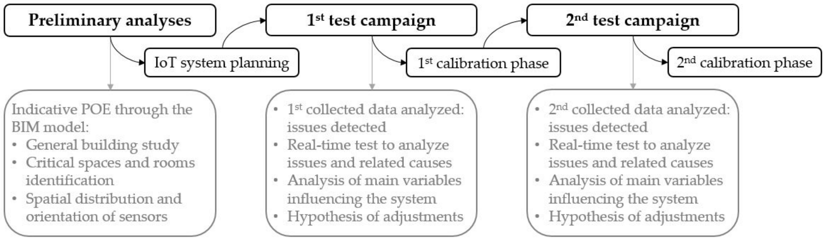
3. Research Project Stages

This paper presents some stages of an ongoing research project. The aim of the research project is to define a Building Management Systems (BMS) based on an occupancy-oriented Digital Twin (DT), evolving from and enriching the Building Information Model (BIM) and integrating occupancy levels and additional relevant data from Post-Occupancy Evaluations (POEs). The expected results of the research project are: monitoring occupancy and defining building occupancy patterns, optimizing current O&M management, building space use and organization, cleaning activities, and, as possible future implementations, applying Smart Contract to cleaning and maintenance services and extending the IoT network with other kind of sensors for safety and quality control. The research project stages are presented in Figure 1.
The first two stages, “definition of BIM guidelines” and “BIM model creation”, have been previously analyzed in a publication by Di Giuda et al. [75]. “Preliminary analyses”, “system installation”, and “test campaigns” are presented in this paper, as they are critical to provide the foundations upon which the occupancy-oriented DT should be based.
The “occupancy-oriented DT” set of activities is currently under development. In future steps of the research, collected data will be analyzed to identify occupancy patterns of the building spaces, and evaluate current management of spaces in terms of people permanence and cleaning frequency. In addition, benchmarks to evaluate optimization strategies will be defined together with the subjects in charge of O&M in the case study building, a fundamental step to evaluate advantages and results of the methodology [76]. The defined occupancy-oriented DT will be the base for the subsequent phase, i.e., “FM scenario definition and optimization”, that will allow the optimization of cleaning activities and contracts that are currently based on the building floor areas, and to reach a better organization and planning of space usage.
Figure 1 also provides “possible future implementations” of the research project. The integration of other kinds of sensors, such as “sensors for safety (man down) and quality control” will allow the monitoring and optimization of different aspects of the building management, resulting in a complete report of building conditions and indoor environmental quality. In addition, a possible future implementation of the system will be the definition of “smart contracts for facility management and cleaning activities” that would be based on the actual need of cleaning defined in previous stages. Smart Contract based on Blockchain technologies and on the occupancy-oriented DT data will provide relevant advantages, i.e., increased network security, reliable data storage, traceability [77], and the possible automation of payments for cleaning activities [78,79].

4. Method

This section provides the methodology applied for the “preliminary analyses” and “test campaigns” stages, analyzed in detail in this article. The “system installation” task was performed by an external consulting company that provided and installed the IoT sensor network, and the platform SophyAI for visualization, storage, and download of collected data.

4.1. IoT Network of Camera-Based Sensors

The “sensors analysis and selection” phase relies on the proposed literature review. As previously stated, most analyzed recent applications aimed at optimizing energy performances and consumptions rather than building operation and use [9,12,16]. Nonetheless, existing studies allowed objectively comparing several available sensor types, supporting the selection of the most suitable type for occupancy monitoring.
Camera-based sensors were selected considering their high accuracy and the possibility to perform other kind of analyses, such as security and safety monitoring, thus allowing for further implementations of new features in the system, increasing the scalability of the system itself.
The limitations of camera-based sensors that have been presented in the literature review section, and how they have been overcome, are described as follows:
  • Detection only within field-of-view of the sensors: the BIM model was used to ensure the best positioning and orientation of sensors and to maximize the area covered by the sensors’ field-of-view;
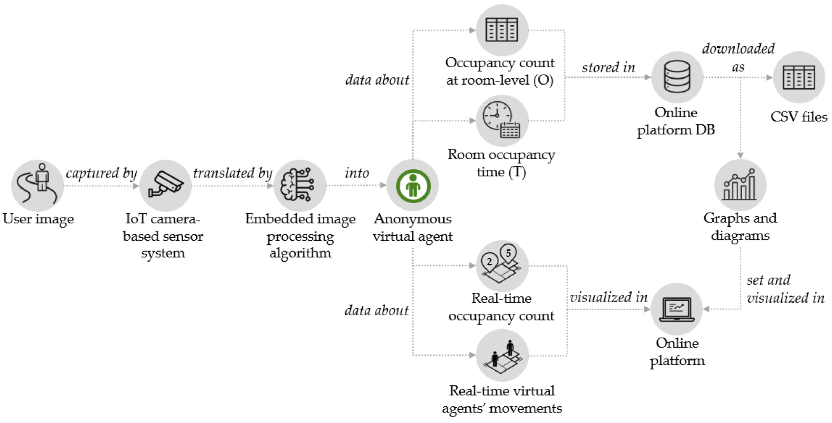
  • Privacy issues and Hawthorne effect: the system was set to anonymously monitor users and not to store any images. The user is recognized as a human by the deep learning algorithm embedded in the camera-based sensors and translated into an anonymous agent that cannot be linked to a specific user identity. Consequently, the movements of the user can be anonymously monitored in real time and visualized in the online platform SophyAI, without storing any real image or video recording.
The sensors can detect occupancy; in particular, they can visualize real time movements of users that are instantaneously transformed into anonymous virtual agents.
The detection of anonymous real-time movements of users is limited to common spaces, i.e., circulation areas and corridors, and they can be visualized in the online platform SophyAI, but are not stored in the database (DB), to protect the users’ privacy. On the contrary, sensors count and store the number of agents that are entering or leaving rooms, which are the main objects of monitoring.
Two values are recorded by the sensors for each monitored room:
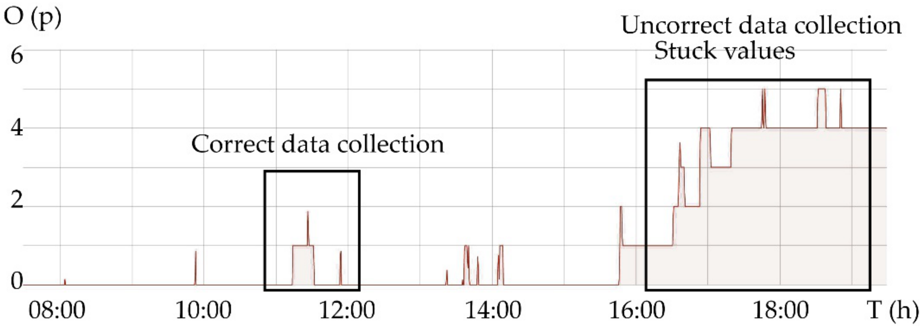
  • O: Occupancy values at room-level, i.e., the number of people (p) occupying a room in a certain period of time;
  • T: Period of time in which one or more virtual agents occupy a room (minutes/hours).

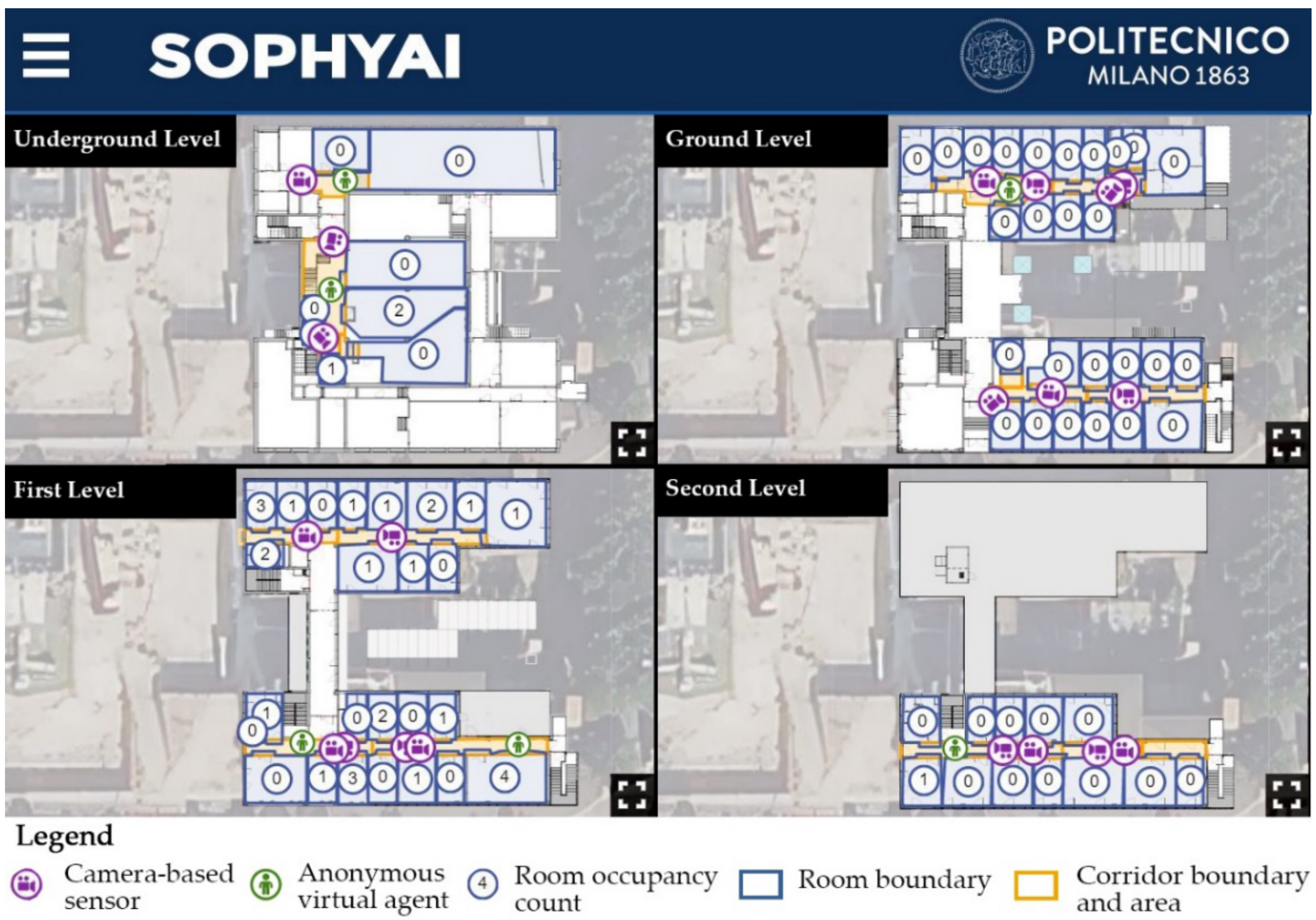
4.2. Visualization and Analysis Platform

A critical theme for real-time monitoring is the possibility of plotting sensors data for visualization, verification, and analyses [23]. Data visualization is a primary subject to support decision-making processes and to help people who are in charge of O&M in reaching management goals, since they may not possess the technical ability to effectively use the indexes and information directly extracted by the sensor system [58].
As shown in Figure 2, the described monitoring system is intertwined with the online platform SophyAI. The platform can:
  • Visualize real-time occupancy count, i.e., the instantaneous value of O of each space;
  • Visualize real-time movements of anonymous virtual agents in a 2D visualization of spaces;
  • Store in a DB data regarding the occupancy count of each space (O) and of each day of the week;
  • Store in a DB data regarding the room occupancy time (T) during each day of the week.
Data stored in the online platform DB can then be downloaded as CSV files that contain the values of O and T for all days of a specified period of time, which could be a week, a month, or a year. In addition, data can be processed in graphs and diagrams and visualized through the online platform.
The online platform displays a 2D visualization of the spaces. Each monitored area is contained in a 2D boundary, which defines the contours of the area itself. The check between the area displayed in the 2D visualization and the 3D view of the same area detected by cameras is a key aspect to correct the optical distortion between the 3D view of the camera and the 2D view of the online platform. The check between 2D boundary and 3D view was performed as a part of the study during the system test and calibration, as described in following paragraphs.

4.3. Preliminary Analyses Based on Post-Occupancy Evaluations and Building Information Modelling

This phase applies Indicative POEs to preliminary analyze the building by means of general and low-invasive analyses, using the BIM model:
  • Analysis of the geometry of spaces: identification of number of levels of the building and number and geometry of rooms. The geometry of spaces influences the number and position of cameras that are needed to monitor the whole space. In addition, the height of spaces represents the maximum height at which the sensor can be installed, and in turn influences the field-of-view of the sensor;
  • Analysis of the functions of spaces: identification of the function of spaces, e.g., bathroom, office, equipment room, etc. The function of spaces influences the definition of the area to be monitored. For example, an equipment room with no variable occupancy, since only technicians can enter the rooms for planned maintenance, does not represent a critical area for occupancy monitoring. As a result, the critical areas whose variable occupancy needs to be monitored are identified. The installation of sensors is limited to the identified critical areas, thus reducing implementation costs of the overall system;
  • Analysis of electrical and data and communication systems: analysis of presence, distribution, and equipment of electrical equipment. A non-homogeneous distribution of the electrical and data wiring can in fact represent a limitation for sensors installation;
  • Simulation of sensors location and orientation: virtual objects representing the sensors are placed into the BIM model, and each virtual sensor is linked to a field-of-view to simulate the area covered and seen by the sensor itself. The height of installation of the sensor also influences the field-of-view. The simulation of several configurations allows the optimization of number, position, and orientation of sensors, maximizing the area covered by sensors.
The use of the BIM model as a source of information and simulation tool to perform the Indicative POE ensures the minimization of user privacy invasiveness. In addition, the sensor system plan is optimized by comparing different configurations.

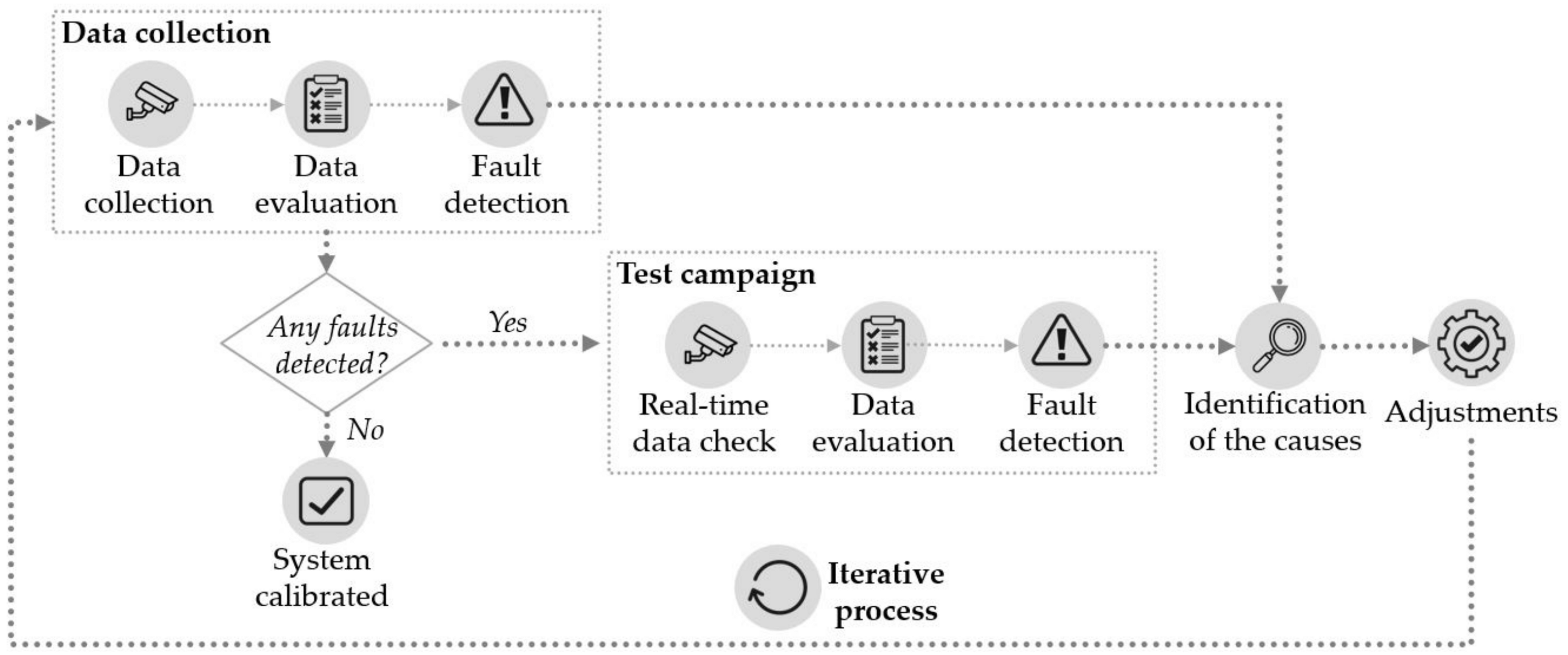
4.4. Test Campaign Methodology for Data Quality Evaluation

The preliminary analyses allow for an efficient planning and installation of sensors, selecting critical areas to be monitored, and optimizing spatial distribution, orientations, and fields-of-view of sensors. Nonetheless, after the first phases of data collection, some errors and faults, described in the following paragraph, may occur, and the system needs to be calibrated to ensure data quality. An incorrect calibration would lead to incorrect data collection and to an erroneous modelling of the occupancy patterns of the spaces, with repercussions on the whole BMS.
The iterative process to perform the “test campaigns” (Figure 1) is presented in detail in Figure 3 and described in the following paragraphs.
Once the system is installed as planned with the support of preliminary analyses, data are collected for a representative period of time that should be identified for each case study. Then collected data are downloaded in CSV format from the online platform DB. Collected data are analyzed in order to identify the possible data errors and related system faults, as described in Table 2. If no faults that could compromise the following analyses are detected, the system is properly functioning and calibrated. Otherwise, test campaigns are performed to verify the errors detected in the collected data.
The real time test campaign involves two operators. One operator (operator A) monitors through the online platform the position and movements of the other operator (operator B) inside the building. The two operators are constantly connected via earphones to communicate and coordinate with each other. In particular, operator A guides operator B towards the areas where errors were previously detected in the collected data. Moving inside the building and entering/exiting the rooms, operator B tests the detection of user movements and the room occupancy count (O) by the system. At the same time, operator A monitors the response of the system by checking the real-time displayed user movements and instantaneous values of O of the rooms through the online platform. Consequently, the operators search for detection errors and system faults in order to identify the causes, as described in Table 2. System faults can be classified as missing data, outliers, stuck values, and noise. Each fault can be identified in collected data or during test campaigns according to specific values of O. In addition, noise can be detected only during real-time test campaigns, by comparing the movements of operator B and his anonymous digital counterpart displayed on the online platform. Some examples of the causes of the errors and faults are camera malfunctioning in the case of missing data and extreme lighting contrast in the monitored area, which impedes a correct detection and causes noisy data.
Once the causes of data errors and faults are identified, some adjustments are proposed and applied to the system. Then the system must be verified again, in an iterative process, until no errors are detected and consequently the required data quality level is reached. This iterative process is also useful to check overtime the effectiveness of improvement solutions or to check the system after geometry changes in the building, e.g., in the case of refurbishments.
Regarding the possible adjustments to solve the errors and the related causes, some general rules were identified to define a hierarchy of possible solutions.
Generally, the most preferable solution would be not acting on the hardware of the system: in the case of a recently added physical obstacle that prevents the camera-based sensor from detecting, the most preferable solution would be moving the object before moving the sensor. In addition, before acting on the hardware part of the system (e.g., adding or replacing cameras), the camera settings could be checked, and the software system would be improved. An example of camera setting adjustment is the modification of contrast and luminance settings of the camera in the case of extreme lighting contrast in the monitored area. In addition, modifying the software is faster, less invasive, and cheaper than working on the hardware. Specifically, the deep learning algorithms of the embedded artificial intelligence system of the cameras for image recognition could be improved and optimized with the support of the external consulting company Laser Navigation srl. Consequently, the adjustments are hierarchized based on those general rules using the following symbols: from the most preferable solution, identified with (++), to the least preferable one, identified with (--).

5. Case Study

The building chosen as case study hosts the Department of Architecture, Built Environment and Construction Engineering (DABC) of Politecnico di Milano, and is located in Milan (Italy). It is a four-story building, hosting administrative offices, research spaces, and university staff offices, for a total of 4300 square meters of gross floor area. Rooms have variable dimensions depending on their use. The building has a symmetrical layout, with a common space in the center and two side corridors. The offices and workspaces are located on either sides of the corridors. Each floor houses at least one bathroom. Before the current study, the building has never been monitored. Therefore, neither data regarding the actual occupancy patterns, nor information about actual cleaning and maintenance activities are currently analyzed and optimized. Furthermore, no space optimization has been performed in relation to the use of available rooms and the actual occupancy indexes at room-level in the building. This case study building acts as prototype for a future application of the proposed method to other university’s buildings.
The case study section is divided in two subsections: the first one describes the application and results of preliminary analyses on the building that supported the planning and installation of the IoT sensor system; the second subsection describes the two test campaigns with specific focus on the detected system faults and related proposed adjustments.

5.1. Preliminary Analyses: Sensors Spatial Distribution and Orientation

A preliminary study of the building (“Indicative POE supported by BIM model” phase as in Figure 1) was performed to identify critical areas to be monitored and to optimize number, position, and orientation of sensors, which in turn allowed the reduction of implementation costs and proper planning of the IoT sensor system.
As described in the methodology section, the preliminary analyses included the following activities that are analyzed in detail in the following paragraphs:
  • Analysis of the functions of spaces;
  • Analysis of the geometry of spaces;
  • Simulation of sensors location and orientation;
  • Analysis of electrical and data and communication systems.

5.1.1. Analysis of the Functions of Spaces

The analysis of the building through the BIM model allowed the identification of number and type of rooms of the building, as shown in Table 3. The BIM model had been previously defined and modeled, as described in Di Giuda et al. [75], who also performed a complete survey to update the as-built documents and to ensure the correspondence between the BIM model and the building. Equipment rooms, storage closets, and archives were excluded, since the only users are cleaning services employees or technicians in charge of maintenance activities. The analyses highlighted that sensors installed in common spaces, i.e., corridors, would be sufficient to monitor room occupancy, i.e., the count of users entering and leaving rooms. Anonymous real-time agent movements are detected only in corridors and can be visualized in the online platform, but are not stored in the DB, to ensure and protect the privacy of users. On the contrary, as regards rooms, the count of number of users (O) and time of occupancy (T) is recorded, as shown in Table 3. The occupancy of critical rooms is monitored to optimize their use, cleanness, and maintenance, while corridors are considered only as circulation areas. As shown in Table 3, 70 rooms out of 87 were selected as critical areas to be monitored.

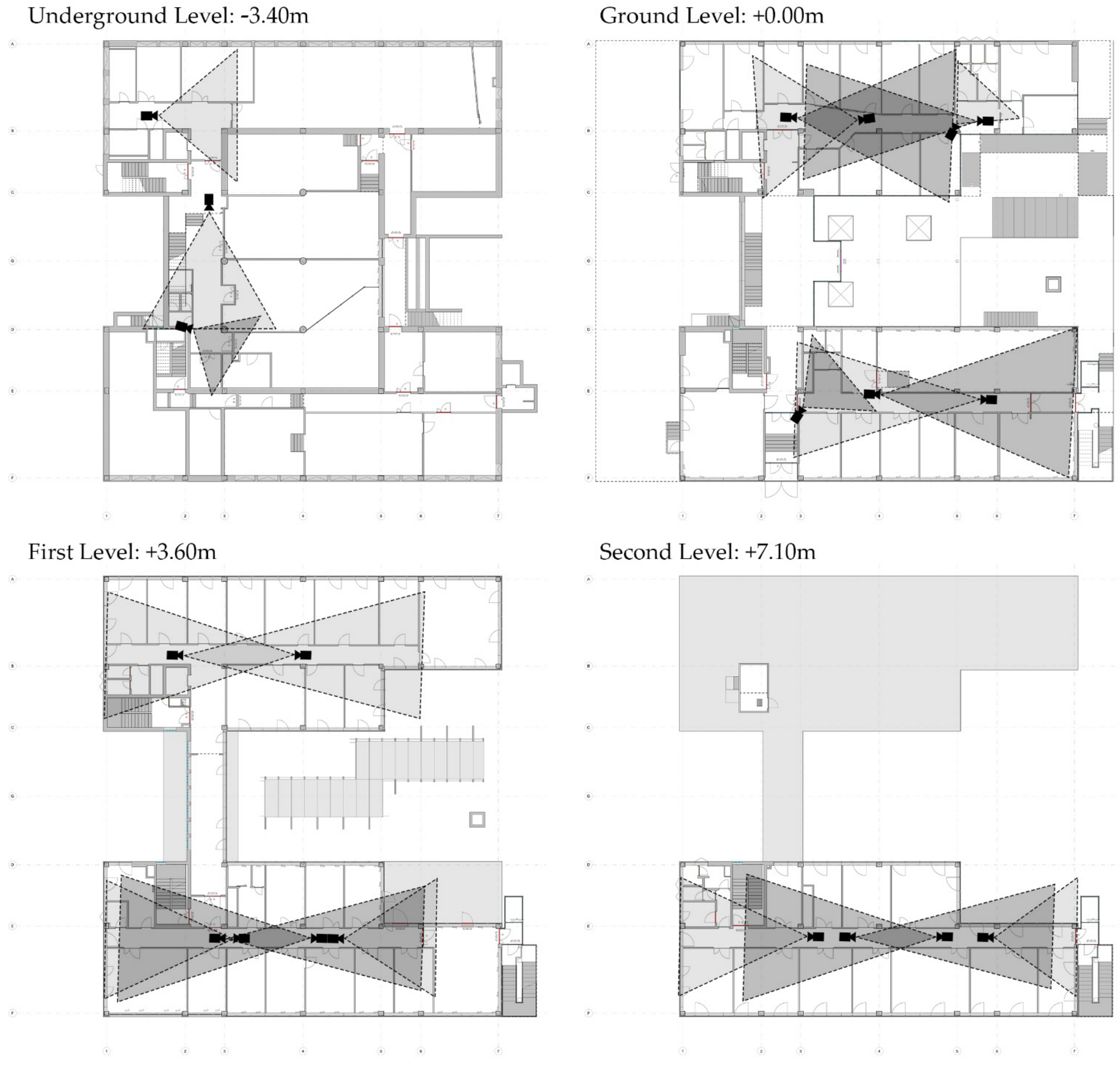
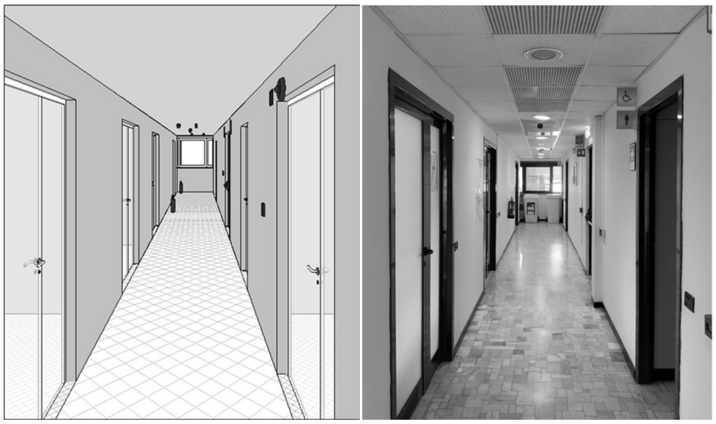
5.1.2. Analysis of the Geometry of Spaces and Simulation of Sensors Location and Orientation

During the preliminary phases regarding the system planning, the BIM model of the building was used to optimize locations and orientations of the camera-based sensors. The geometry analysis highlighted that the building corridors are long, low ceiling, and narrow (length: 32 m; height: 2.40–2.70 m; width: 1.60 m). Three simulations of the interrelated position of the sensors in a corridor have been performed to define the best configuration. Virtual objects representing the sensors were added to the BIM model in different locations according to the three possible configurations. Each virtual sensor was then linked to a field-of-view that allowed to virtually check through the model the area covered by each sensor. The BIM-based simulation analyzed three possible configurations, as shown in Figure 4:
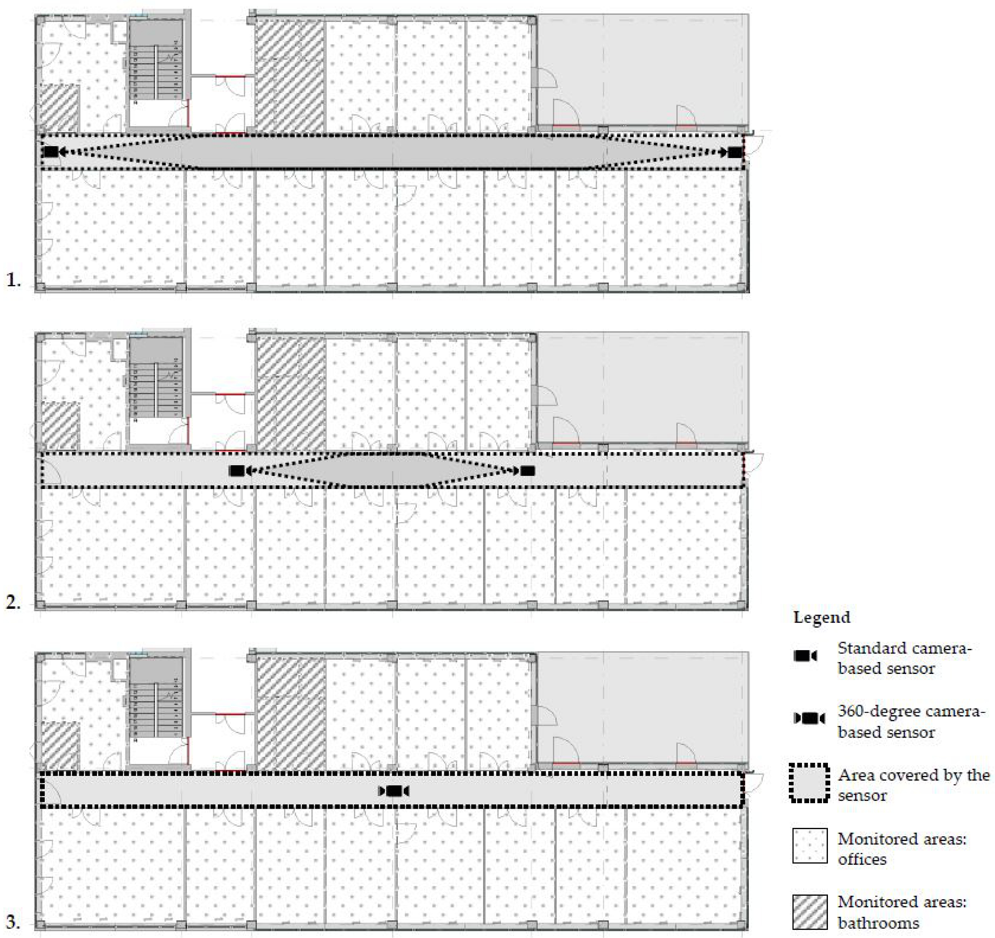
  • The first solution considered two standard cameras at the two opposite sides of the corridor. Each corridor would be entirely monitored by two sensors at the same time, but in the central area, the detection could be less precise due to the distance from the sensors. In addition, cameras would have difficulty in monitoring areas near the end of the corridor, i.e., the area close to each sensor. Users passing through a door near the end of the corridor would be extremely distorted in the view of the nearby camera, making recognition difficult.
  • The second solution considered two standard camera-based sensors located at 1/3 and 2/3 of the corridor. This solution allows for a better monitoring of the end areas of corridors, but limits the simultaneous monitoring by both sensors to the central area only.
  • The third solution implied the use of a single 360-degree camera at the center of the corridor. Those kind of sensors are more expensive than standard cameras, but the total cost would be comparable, since this solution would consider only one sensor instead of two. This solution results in the corridor being entirely monitored by a single camera.
The chosen solution was the second one, since in many cases there are doors near the end of corridors, thus excluding the first solution. In addition, due to the reduced width of the corridors, one single camera could struggle in identifying two people walking lined up. Therefore, the third solution, which involved only one camera, was also less preferable than the second one.
The chosen sensors are High Quality Bullet Pro Camera PoE, with the following features: they provide HD quality images; the Power over Ethernet (PoE) allows to supply power and network connection to the camera with a single cable; a Wide Dynamic Range (WDR) allows to compensate problems due to exposure to light; the view angle of the camera reaches a maximum of 110 degrees. The system is installed in a dedicated Virtual Local Area Network (VLAN), and a static IP is provided for each element of the system. As stated in the Introduction, the sensor system was provided by a third-party organization, Laser Navigation Srl, who operated in full compliance with EU General Data Protection Regulation (GDPR). In fact, the deep learning algorithm does not record images, but only metadata regarding the anonymous movements and count of users are processed by the system, inhibiting the recognition of the observed subjects.
The 20 sensors were installed directly in the ceiling, i.e., at height 2.40/2.70 m depending on the level of the building, ensuring the maximum coverage area. Figure 5 shows the plan of the IoT sensors system in the case study building.
The BIM model also allowed for an optimization of the field-of-view of the sensors, as shown in Figure 6. The virtual camera field-of-view simulation supported the definition of the best orientation, i.e., the best tilt angle of each camera on x- and y-axis. This ensured that all the offices and bathrooms defined as critical, whose occupancy needed to be monitored, were correctly detected by the sensors.

5.1.3. Analysis of Electrical and Data and Communication Systems

The last preliminary analysis performed with the BIM model was the check of the electrical and data system equipment and wiring distribution already available in the building. The analysis showed that since cameras would be installed in corridors, all the necessary wiring was already available. Therefore, no implementation was needed to install the system.

5.2. Test Campaigns

Once the preliminary analyses had been performed, the system had been installed. First data collection was performed, and collected data were analyzed to identify issues and faults. Data were collected during a three-month period, i.e., the representative period, as it is the minimum period of time to encounter all possible activities conducted by the users of the department. A qualitative analysis was conducted on the collected dataset to identify rough errors.
Figure 7 shows a graph of collected data about a bathroom during one day. Stuck values are identified since 4 p.m., because the occupancy raises but never decreases. It is a stuck value because the bathroom can host only one person at a time; therefore, a continuous occupancy of four people represents without any doubt a blunder in the detection. The solution to this specific problem is provided in Table 4.
After faults of the system were detected, a first test campaign was performed to understand the causes and propose improvements for the system. Detected data were tested in real time by two operators, as described in the method, to identify the causes of system faults. An example of the visualization of real time data in the online platform is shown in Figure 8.
This first test campaign was followed by a second test campaign, to properly calibrate the system and ensure detected data quality, as shown in Figure 9. The two test campaigns were carried out during different periods of the year. This represented a key aspect for the recognition of lighting contrast issues. The first test campaign was performed in June 2020, with data collection for a three-month period from November 2019 to January 2020. The first test campaign was performed after the end of the first Italian shutdown period due to COVID-19 pandemic (early March–early June 2020). The second test campaign was performed in November 2020, with data collected for another three-month period from July to October 2020, excluding August, during which the building is usually under-occupied due to summer holidays. After the shutdown period March–June 2020, administrative and research activities have been resumed. Therefore, all the data collected for system test and calibration can be considered reliable.

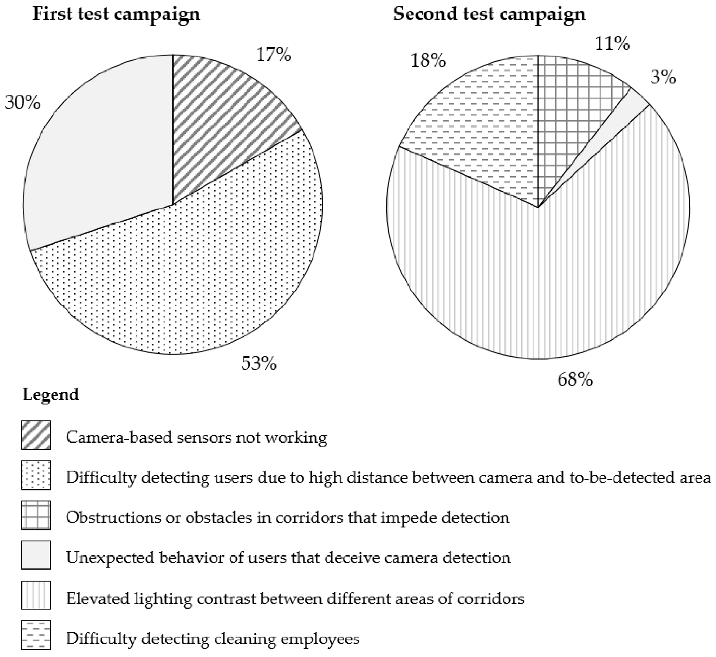
6. Results and Discussion

Table 4 provides a resume of errors, related evaluation criteria, fault identification and classification, causes of the faults, and proposed solutions, hierarchized and listed from the most preferable one (++) to the least preferable one (--) of the two test campaigns.
The first test campaign highlighted the following issues:
  • Difficulty of the system in detecting two people entering in a room close together and/or quickly;
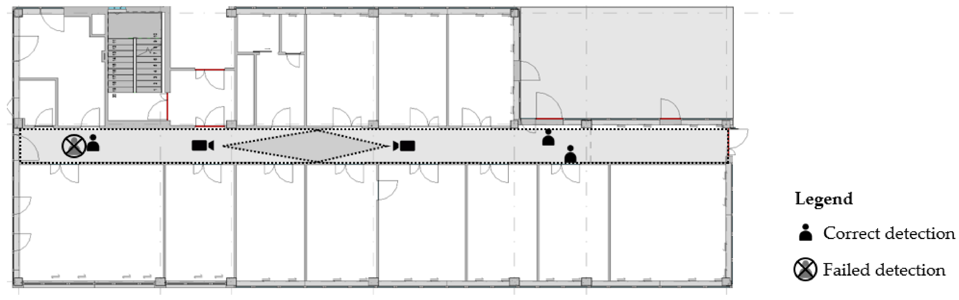
  • Issues in the detection of two people walking in a corridor towards a sensor, since the person further away from the camera is not detected. The error occurs in all areas not covered by the fields of view of two cameras at the same time;
  • Irregular detection of users with a continuous detection/disappearance of a moving user due to the high distance between the camera and the to-be-detected area. This issue was in fact detected mainly in areas far from the sensors.
The identified issues are mainly due to the geometry of corridors, which are low ceiling, long, and narrow. Due to the limited height of the corridor, the cameras struggle in detecting people walking in groups or lined up (Figure 10). The issues led to an incorrect user detection affecting the displayed data in the online platform. However, while the possibility of having people walking lined up or in groups in corridors is relatively high, the probability of two or more people entering a room simultaneously is low, due to the standard dimensions of the doors, that allow the entrance of one person at a time. For this reason, it is possible to ignore these issues. To overcome the issue related to irregular detection of users due to the distance of areas from the camera, improvement in the deep learning algorithms for image recognition were implemented.
Considering the online platform, a major issue was related to the values indicating the presence of people in the rooms showing a negative value or a high positive value. This means that, according to the collected data, many people were entering or leaving the room in a very short time. Automatic routines to solve and mitigate incorrect data have been implemented to the software:
  • Automatism that brings the count back to 0 when the displayed count is negative;
  • Possibility to manually reset rooms that present a wrong count;
  • Automatic routine that records the occupancy data after a minimum user presence (i.e., 5 min) for office spaces only.
The improvement of the automatic routine solves the related problem of users’ behavior that deceive the detection system, such as standing in front of the door when opening the office or talking right in front of the entry of a room.
After the modifications and improvements applied, data have been collected for a period of three months from July to October 2020, excluding August for lower building occupancy due to summer holidays, to verify the effectiveness of the strategies adopted.
The qualitative analysis of the second dataset highlighted a general improvement in detection capabilities of the system, since technical issues were not identified anymore, but some faults occurred anyway. Therefore, a second real-time test campaign was carried out in November 2020, resulting in the following sensor-related issues:
  • Difficulty in detecting users at the end of the corridors due to the presence of windows. The intense natural light generates a high luminous contrast between the central part of the corridor and the terminal part. The light contrast of the two zones generates an unstable detection of users. The detecting issue related to lighting contrasts of different zones of the building was only discovered in the second test campaign and not during the previous test. Considering the location of the building (Milan, 45°28′46.8″ N 9°13′48.0″ E), the sun is low in the sky during the winter season. This can generate detection issues related to lighting contrast, which cannot be detected during others seasons of the year, which explains the newly emerged detection issue, since the first test campaign had been performed in May. Therefore, conducting several tests during different periods of the day and year is strongly recommended for camera-based sensor systems. A preferable solution to overcome the lighting contrast issue is modifying the settings of the camera to correct the lighting contrast.
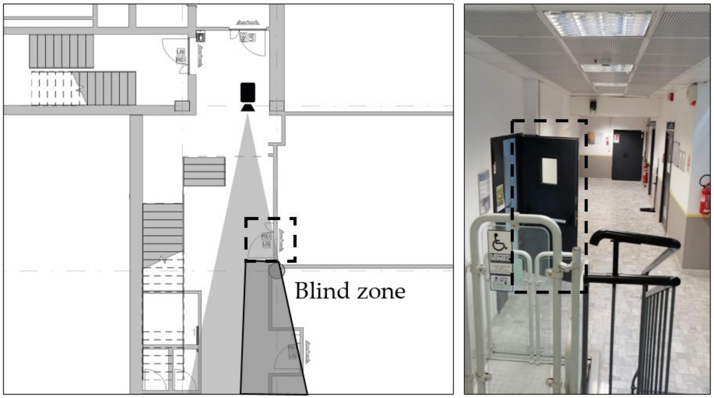
  • Failure in detecting the users’ entrance due to other kind of obstructions such as open doors. Specifically, the doors opening towards the corridor can obstruct the view of the adjacent room entrance, preventing the system from registering users entering the room (Figure 11). The issue can only be managed by adding new cameras to cover the unexpected blind spots. The issue was unexpected, since doors are usually kept closed when offices are occupied.
  • Issues in the recognition of cleaning service company employees. The system struggled in detecting the workers due to the presence of the cleaning trolley, which impeded a complete view of the operator. The cleaning trolley provoked an incorrect counting of entries, exits, and occupancy of the rooms. To overcome the issue, the recognition algorithm can be optimized and trained to correctly recognize the cleaning service operator, by recognizing the cleaning trolley.
Figure 12 presents the percentages of error types detected during the two test campaigns. During the first test campaign, 30 out of 70 monitored rooms presented detection faults, while during the second test campaign, 38 rooms presented detection issues. The reason of the higher number of faults during the second test campaign is mainly due to the lighting issues that emerged only during the second test campaign.
During the first test campaign, 70% of errors were related to technical issues: 17% of errors due to not-working cameras, and 53% of errors due to difficulty detecting users in areas too far from the camera-based sensors. As shown in Figure 12, these types of technical issues were completely fixed by adjusting the system settings. Once all cameras were properly working and correctly set, those issues did not occur in subsequent analyses.
Another type of issue detected in the first test campaign was related to unexpected user behavior, resulting in 30% of errors. These errors could be adjusted with some improvements in the system. However, a 3% of errors due to unexpected user behavior occurred also during the second test campaign. Despite the error percentage being significantly lower in the second test campaign, this type of error could not be completely avoided because of the unpredictable nature and high variability of user behavior.
Regarding the second test campaign, elevated lighting contrasts between different areas of corridors caused 68% of errors. This kind of error was never detected during the first test campaign because of the different period of the year when the test was performed, a key aspect for proper calibration of a camera-based sensors system.
The remaining 30% of errors of the second test campaign were related to difficulties detecting the cleaning employee (18%) and to obstructions and obstacles that impeded the detection (11%). Cleaning employee detection issues were classified as a technical error in the first campaign. After the resolution of technical issues, the error persisted, and the actual cause was identified, highlighting the importance of a multi-stage testing of the system. Detection issues related to obstacles and obstructions appeared because some pieces of furniture were moved or spaces were reorganized. The frequent check of the correct functioning of the system overtime is fundamental to verify newly appeared issues and consequently adjust and improve the system.
A comparison of these results with other systems could be helpful to provide an assessment of the proposed system. As previously underlined, the setting and calibration of monitoring system has frequently been neglected in existing literature, and the accuracy of IoT systems applied to DTs is often taken for granted. Available data regard, as shown in Table 1, the accuracy of specific sensors’ typologies, but do not address the accuracy of systems, which depends on several variables, e.g., building features and use, number of sensors, etc. The test campaigns here presented have been used to explore and improve the efficiency of the entire systems of DT.
For this reasons, these results obtained from the case-study building cannot be compared to other systems, based on different typologies of sensors. The provided case study application is useful to define guidelines to calibrate IoT camera-based sensors system.

7. Conclusions and Further Developments

This work presents the development of first steps of an ongoing research project to define a Building Management System (BMS) for facility management, especially regarding the occupancy and cleaning activities in office buildings that would be based on an occupancy-oriented Digital Twin (DT). The proposed BMS would ensure better space management, organization, and cleaning, since the system would detect actual occupancy levels and related needs for cleaning activities. The advantages result in optimizations of cost and space use, as well as customized cleaning activities and contracts.
In particular, this study presented the IoT system calibration phases, i.e., the preliminary analyses to optimize the planning of the IoT camera-based sensors system, and the test campaigns, in order to ensure the system efficiency and accuracy to monitor occupancy. A key aspect of the definition of a DT has been in fact identified in the data connection between physical asset and virtual counterpart, the main components of a DT. In addition, the data quality is a critical aspect to ensure the quality of the results of the analyses, simulations, and predictions performed on the virtual model.
The case study section highlighted that the preliminary analyses, i.e., Indicative Post-Occupancy Evaluations (POE) supported by the use of the BIM model, were important to plan the IoT system, in particular as regards number, locations, and orientation of the sensors. The analyses allowed the identification of offices and bathrooms as main spaces to be monitored. In addition, the observed configuration of building spaces allowed planning the sensors installation only in corridors, from which it is possible to detect entries and exits from the different rooms. The BIM model allowed for simulations of sensors location and fields-of-view.
As regards the two test campaigns results, some system faults and related causes were identified and solved. The issues generated by user behavior were the least predictable, trivial, and at the same time the most difficult and expensive to solve, requiring the installation of new cameras. The variability of human behavior inside a building is very high; the calibration of the system must cover a sufficient period of time to bring out all problems related to human behaviors. Considering the complexity of the monitoring system and the high dynamicity of the variables involved (e.g., fast-changing spatial conditions and user behavior), a multi-stage test and calibration campaign was fundamental for the correct setting of a camera-based sensor system.
Another interesting aspect resulting from the test campaigns was the influence that the period of the year had on the test itself, due to changing lighting conditions.
Other relevant aspects are the geometric features of the to-be-monitored spaces. For example, the limited width and height of the corridors led to some difficulties in detecting more users moving together. However, those issues did not have critical effects on the collected data. The boundary conditions of the system should be carefully checked, as they could have negative consequences on collected data and on data analyses.
The use of an online platform was useful to real-time check and evaluate data during the test campaigns, as well as to remote controlling the monitoring system.
Once the system is tested and assessed, further developments of the research will regard the proper monitoring of the building. As of now, qualitative analyses have been performed on collected dataset to identify rough errors, and by means of the two test campaigns, the causes of the faults have been identified and solved. During the next phases of the research project, quantitative analyses will be conducted on collected datasets, which will be the basis for the definition of the occupancy-oriented DT. DT analyses and simulations, and resulting optimization scenarios, will be proposed and analyzed to identify real advantages and limitations of the proposed methodology. The proposed method, once completely tested and refined on the case study building, could be extended to large building stock, supporting the decision-making process of building owners and building managers.
Potential applications of the system would entail the integration of other kind of sensors to monitor Indoor Air Quality (IAQ), carbon dioxide, temperature, humidity, and Volatile Organic Compounds (VOC) levels, resulting in a more complete evaluation of the building conditions and Indoor Environmental Quality (IEQ). Sensors could play an important role for safety management purposes. The combined use of the system with Smart Contract and Blockchain technology could ensure increased network security, reliable data storage, traceability of data, and the possible automation of payments for cleaning activities. Cleaning contracts could in fact be customized based on the actual use of spaces, detected by the proposed system.

Author Contributions

Conceptualization: E.S., M.L., and L.P.; methodology: E.S., M.L., and L.P.; software: L.P. and G.P.; validation: E.S, M.L., L.P., G.P., G.M.D.G., L.C.T., and G.B.; formal analysis: E.S., M.L., and L.P.; investigation: M.L., L.P., and G.P.; resources: G.M.D.G.; data curation: M.L. and L.P.; writing—original draft preparation: E.S., M.L., and L.P.; writing—review and editing: E.S, M.L., L.P., G.P., G.M.D.G., L.C.T., and G.B.; visualization: E.S., M.L., and L.P.; supervision: G.M.D.G., L.C.T., and G.B..; project administration, G.M.D.G.; funding acquisition, G.M.D.G. All authors have read and agreed to the published version of the manuscript.

Funding

This research received no external funding.

Institutional Review Board Statement

Not applicable.

Informed Consent Statement

Not applicable.

Data Availability Statement

Restrictions apply to the availability of these data. Data was obtained from Department of Architecture, built environment and construction engineering and are available from the authors with the permission of Department of Architecture, built environment and construction engineering party.

Acknowledgments

The authors thank Eng. Marco Schievano and Eng. Francesco Paleari, and the Department of Architecture, Built Environment, and Construction Engineering for the support in the ongoing research. This research is developed in collaboration with Laser Navigation srl.

Conflicts of Interest

The authors declare no conflict of interest.

References

  1. National Research Council. Stewardship of Federal Facilities: A Proactive Strategy for Managing the Nation’s Public Assets; The National Academies Press: Washington, DC, USA, 1998. [Google Scholar]
  2. Zimmerman, A.; Martin, M. Post-occupancy evaluation: Benefits and barriers. Build. Res. Inf. 2001, 29, 168–174. [Google Scholar] [CrossRef]
  3. Bento Pereira, N.; Calejo Rodrigues, R.; Fernandes Rocha, P.; Bento Pereira, N.; Calejo Rodrigues, R.; Fernandes Rocha, P. Post-Occupancy Evaluation Data Support for Planning and Management of Building Maintenance Plans. Buildings 2016, 6, 45. [Google Scholar] [CrossRef] [Green Version]
  4. Dong, B.; Yan, D.; Li, Z.; Jin, Y.; Feng, X.; Fontenot, H. Modeling occupancy and behavior for better building design and operation—A critical review. Build. Simul. 2018, 11, 899–921. [Google Scholar] [CrossRef]
  5. Kim, J.; de Dear, R. Nonlinear relationships between individual IEQ factors and overall workspace satisfaction. Build. Environ. 2012, 49, 33–40. [Google Scholar] [CrossRef] [Green Version]
  6. Agha-Hossein, M.M.; El-Jouzi, S.; Elmualim, A.A.; Ellis, J.; Williams, M. Post-occupancy studies of an office environment: Energy performance and occupants’ satisfaction. Build. Environ. 2013, 69, 121–130. [Google Scholar] [CrossRef]
  7. Straka, V.; Aleksic, M. Post-occupancy evaluation: Three schools from Greater Toronto. In Proceedings of the PLEA2009–26th Conference on Passive and Low Energy Architecture, Quebec City, QC, Canada, 22–24 June 2009. [Google Scholar]
  8. Rogage, K.; Clear, A.; Alwan, Z.; Lawrence, T.; Kelly, G. Assessing Building Performance in Residential Buildings using BIM and Sensor Data. Int. J. Build. Pathol. Adapt. 2019. [Google Scholar] [CrossRef]
  9. Wang, W.; Hong, T.; Xu, N.; Xu, X.; Chen, J.; Shan, X. Cross-source sensing data fusion for building occupancy prediction with adaptive lasso feature filtering. Build. Environ. 2019, 162, 106280. [Google Scholar] [CrossRef] [Green Version]
  10. De Wilde, P. The gap between predicted and measured energy performance of buildings: A framework for investigation. Autom. Constr. 2014, 41, 40–49. [Google Scholar] [CrossRef]
  11. Marzouk, M.; Abdelaty, A. BIM-based framework for managing performance of subway stations. Autom. Constr. 2014, 41, 70–77. [Google Scholar] [CrossRef]
  12. Costa, A.A.; Lopes, P.M.; Antunes, A.; Cabral, I.; Grilo, A.; Rodrigues, F.M. 3I Buildings: Intelligent, Interactive and Immersive Buildings. Procedia Eng. 2015, 123, 7–14. [Google Scholar] [CrossRef] [Green Version]
  13. Yang, J.; Santamouris, M.; Lee, S.E. Review of occupancy sensing systems and occupancy modeling methodologies for the application in institutional buildings. Energy Build. 2016, 121, 344–349. [Google Scholar] [CrossRef]
  14. Daher, E.; Kubicki, S.; Guerriero, A. Post-occupancy evaluation parameters in multi-objective optimization-based design process. In Advances in Informatics and Computing in Civil and Construction Engineering; Springer: Cham, Switzerland, 2018. [Google Scholar]
  15. Demian, P.; Liu, Z.; Deng, Z. Integration of Building Information Modelling (BIM) and Sensor Technology: A Review of Current Developments and Future Outlooks. In Proceedings of the 2nd International Conference on Computer Science and Application Engineering (CSAE), Chicago, IL, USA, 1–3 October 2018. [Google Scholar]
  16. Saralegui, U.; Anton, M.A.; Arbelaitz, O.; Muguerza, J. An IoT sensor network to model occupancy profiles for energy usage simulation tools. In Proceedings of the 2018 Global Internet of Things Summit, Bilbao, Spain, 4–7 June 2018. [Google Scholar]
  17. Ouf, M.M.; O’Brien, W.; Gunay, B. On quantifying building performance adaptability to variable occupancy. Build. Environ. 2019, 155, 257–267. [Google Scholar] [CrossRef]
  18. Capolongo, S.; Rebecchi, A.; Buffoli, M.; Appolloni, L.; Signorelli, C.; Fara, G.M.; D’Alessandro, D. COVID-19 and cities: From urban health strategies to the pandemic challenge. a decalogue of public health opportunities. Acta Biomed. 2020, 91, 13–22. [Google Scholar]
  19. Grieves, M.W.; Vickers, J. Digital Twin: Mitigating Unpredictable, Undesirable Emergent Behavior in Complex Systems. In Transdisciplinary Perspectives on Complex Systems: New Findings and Approaches; Springer: Cham, Switzerland, 2017; pp. 85–113. ISBN 9783319387567. [Google Scholar]
  20. Lu, Q.; Xie, X.; Parlikad, A.K.; Schooling, J.M.; Konstantinou, E. Moving from Building Information Models to Digital Twins for Operation and Maintenance. In Proceedings of the Institution of Civil Engineers—Smart Infrastructure and Construction; ICE Publishing: London, UK, 2020; pp. 1–9. [Google Scholar]
  21. Dawkins, O.; Dennett, A.; Hudson-Smith, A. Living with a Digital Twin: Operational management and engagement using IoT and Mixed Realities at UCL’s Here East Campus on the Queen Elizabeth Olympic Park. In Proceedings of the 26th Annual GIScience Research UK Conference: GISRUK 2018, Leicester, UK, 17–20 April 2018; p. 7. [Google Scholar]
  22. Manngård, M.; Lund, W.; Björkqvist, J. Using Digital Twin Technology to Ensure Data Quality in Transport Systems. In Proceedings of the 8th Transport Research Arena TRA, Helsinki, Finland, 27–30 April 2020. [Google Scholar]
  23. Boje, C.; Guerriero, A.; Kubicki, S.; Rezgui, Y. Towards a semantic Construction Digital Twin: Directions for future research. Autom. Constr. 2020, 114, 103179. [Google Scholar] [CrossRef]
  24. Tomko, M.; Winter, S. Beyond digital twins—A commentary. Environ. Plan. B Urban Anal. City Sci. 2019, 46, 395–399. [Google Scholar] [CrossRef]
  25. Yang, J.; Pantazaras, A.; Chaturvedi, K.A.; Chandran, A.K.; Santamouris, M.; Lee, S.E.; Tham, K.W. Comparison of different occupancy counting methods for single system-single zone applications. Energy Build. 2018, 172, 221–234. [Google Scholar] [CrossRef]
  26. Yan, D.; Hong, T.; Dong, B.; Mahdavi, A.; D’Oca, S.; Gaetani, I.; Feng, X. IEA EBC Annex 66: Definition and simulation of occupant behavior in buildings. Energy Build. 2017, 156, 258–270. [Google Scholar] [CrossRef] [Green Version]
  27. Preiser, W.F.E. Post-occupancy evaluation: How To Make Buildings Work Better. Facilities 1995, 13, 19–28. [Google Scholar] [CrossRef]
  28. Manning, P. Office Design: A Study of Environment; Manning, P., Ed.; The Pilkington Research Unit, Department of Building Science, University of Liverpool: Liverpool, UK, 1965. [Google Scholar]
  29. Hadjri, K.; Crozier, C. Post-occupancy evaluation: Purpose, benefits and barriers. Balt. J. Manag. 2009, 27, 21–33. [Google Scholar] [CrossRef]
  30. National Research Council. Learning from Our Buildings: A State-of-the-Practice Summary of Post-Occupancy Evaluation; National Academies Press: Washington, DC, USA, 2001; ISBN 9780309076111. [Google Scholar]
  31. Preiser, W.F.E.; Rabinowitz, H.Z.; White, E.T. Post-Occupancy Evaluation; Van Nostrand Reinhold: New York, NY, USA, 1988. [Google Scholar]
  32. Li, P.; Froese, T.M.; Brager, G. Post-occupancy evaluation: State-of-the-art analysis and state-of-the-practice review. Build. Environ. 2018, 133, 187–202. [Google Scholar] [CrossRef] [Green Version]
  33. Preiser, W.F.E.; Schramm, U. Building Performance Evaluation. In Time-Saver Standards for Architectural Design Data; Watson, D., Crosbie, M.J., Callender, J.H., Eds.; McGraw-Hill Professional Publishing: New York, NY, USA, 1997. [Google Scholar]
  34. Boarin, P.; Besen, P.; Haarhoff, E. Post-Occupancy Evaluation of Neighbourhoods: A Review of the Literature; Building Better Homes Towns and Cities Working Papers; 2018. Available online: https://www.buildingbetter.nz/resources/publicationsand (accessed on 18 July 2020).
  35. Preiser, W.F.E.; Nasar, J.L. Assessing Building Performance: Its evolution from Post-occupancy Evaluation. ArchNet-IJAR 2008, 2, 84–99. [Google Scholar]
  36. Preiser, W.F.E. Building Performance Assessment—From POE to BPE: A Personal Perspective. Archit. Sci. Rev. 2005, 48, 201–205. [Google Scholar] [CrossRef]
  37. Durosaiye, I.O.; Hadjri, K.; Liyanage, C.L. A critique of post-occupancy evaluation in the UK. J. Hous. Built Environ. 2019, 34, 345–352. [Google Scholar] [CrossRef] [Green Version]
  38. Zimring, C.M.; Reizenstein, J.E. Post-Occupancy Evaluation: An Overview. Environ. Behav. 1980, 12, 429–450. [Google Scholar] [CrossRef]
  39. Di Giuda, G.M.; Pellegrini, L.; Schievano, M.; Locatelli, M.; Paleari, F. BIM and Post-occupancy evaluations for building management system: Weaknesses and opportunities. In Springer Volume Research for Developmen—La Digitalizzazione dei Processi per la Progettazione, Costruzione e Gestione Dell’ambiente Costruito; Springer International Publishing: Cham, Switzerland, 2020; pp. 319–327. ISBN 9783030335700. [Google Scholar]
  40. Alonso, R.; Borras, M.; Koppelaar, R.H.E.M.; Lodigiani, A.; Loscos, E.; Yöntem, E. SPHERE: BIM Digital Twin Platform. Proceedings 2019, 20, 6. [Google Scholar] [CrossRef] [Green Version]
  41. Oti, A.H.; Kurul, E.; Cheung, F.K.T.; Tah, J.H.M. A framework for the utilization of Building Management System data in building information models for building design and operation. Autom. Constr. 2016, 72, 195–210. [Google Scholar] [CrossRef] [Green Version]
  42. Codinhoto, R.; Kiviniemi, A. BIM for FM: A case support for business life cycle. IFIP Adv. Inf. Commun. Technol. 2014, 442, 63–74. [Google Scholar]
  43. Machado, F.A.; Dezotti, C.G.; Ruschel, R.C. The interface layer of a BIM-IoT prototype for energy consumption monitoring. In Systems, Controls, Embedded Systems, Energy, and Machines; CRC Press: Boca Raton, FL, USA, 2017; pp. 9-1–9-10. [Google Scholar] [CrossRef] [Green Version]
  44. Underwood, J.; Isikdag, U. Emerging technologies for BIM 2.0. Constr. Innov. 2011, 11, 252–258. [Google Scholar] [CrossRef]
  45. Pin, C.; Medina, C.; McArthur, J.J. Supporting post-occupant evaluation through work order evaluation and visualization in FM-BIM. In Proceedings of the ISARC 2018—35th International Symposium on Automation and Robotics in Construction and International AEC/FM Hackathon: The Future of Building Things, Berlin, Germany, 20–25 July 2018; pp. 32–39. [Google Scholar]
  46. Lu, Q.; Parlikad, A.K.; Woodall, P.; Don Ranasinghe, G.; Xie, X.; Liang, Z.; Konstantinou, E.; Heaton, J.; Schooling, J.M. Developing a Digital Twin at Building and City Levels: A Case Study of West Cambridge Campus. J. Chem. Inf. Model. 2019, 53, 1689–1699. [Google Scholar] [CrossRef]
  47. Grieves, M.W. Product lifecycle management: The new paradigm for enterprises. Int. J. Prod. Dev. 2005, 2, 71–84. [Google Scholar] [CrossRef]
  48. Grieves, M.W. Product Lifecycle Management: Driving the Next Generation of Lean Thinking; McGraw-Hill Education: New York, NY, USA, 2006; ISBN 978-0071452304. [Google Scholar]
  49. Grieves, M.W. Virtually Perfect: Driving Innovative and Lean Products through Product Lifecycle Management; Space Coast Press: Cocoa Beach, FL, USA, 2011; ISBN 978-0982138007. [Google Scholar]
  50. Shafto, M.; Conroy, M.; Doyle, R.; Glaessgen, E.H.; Kemp, C.; LeMoigne, J.; Wang, L. Modeling, Simulation, Information Technology & Processing Roadmap-Technology Area 11; National Aeronautics and Space Administration: Washington, DC, USA, 2012. [Google Scholar]
  51. Glaessgen, E.H.; Stargel, D.S. The digital twin paradigm for future NASA and U.S. Air force vehicles. In Proceedings of the Collection of Technical Papers—53rd AIAA/ASME/ASCE/AHS/ASC Structures, Structural Dynamics and Materials Conference, Honolulu, HI, USA, 23–26 April 2012; pp. 1–14. [Google Scholar]
  52. Knapp, G.L.; Mukherjee, T.; Zuback, J.S.; Wei, H.L.; Palmer, T.A.; De, A.; DebRoy, T. Building blocks for a digital twin of additive manufacturing. Acta Mater. 2017, 135, 390–399. [Google Scholar] [CrossRef]
  53. Bolton, A.; Blackwell, B.; Dabson, I.; Enzer, M.; Evans, M.; Fenemore, T.; Harradence, F.; Keaney, E.; Kemp, A.; Luck, A.; et al. The Gemini Principles: Guiding Values for the National Digital Twin and Information Management Framework; University of Cambridge: Cambridge, UK, 2018. [Google Scholar]
  54. High Value Manufacturing Catapult Visualization and VR Forum. Feasibility of an Immersive Digital Twin: The Definition of a Digital Twin and Discussions around the Benefit of Immersion. 2018. Available online: hvm.catapult.org.uk (accessed on 18 July 2020).
  55. National Infrastructure Commission. Data for the Public Good. 2017. Available online: https://nic.org.uk/ (accessed on 18 July 2020).
  56. Batty, M. Digital twins. Environ. Plan. B Urban Anal. City Sci. 2018, 45, 817–820. [Google Scholar] [CrossRef]
  57. Al-Sehrawy, R.; Kumar, B. Digital Twins in Architecture, Engineering, Construction and Operations. A Brief Review and Analysis. Lect. Notes Civ. Eng. 2021, 98, 924–939. [Google Scholar]
  58. Love, P.E.D.; Matthews, J. The ‘how’ of benefits management for digital technology: From engineering to asset management. Autom. Constr. 2019, 107, 15. [Google Scholar] [CrossRef]
  59. Lu, Q.; Parlikad, A.K.; Woodall, P.; Ranasinghe, G.D.; Heaton, J. Developing a Dynamic Digital Twin at a Building Level: Using Cambridge Campus as Case Study. In Proceedings of the International Conference on Smart Infrastructure and Construction 2019 (ICSIC): Driving Data-Informed Decision-Making, Cambridge, UK, 8–10 July 2019; pp. 67–75. [Google Scholar]
  60. Haag, S.; Anderl, R. Digital twin—Proof of concept. Manuf. Lett. 2018, 15, 64–66. [Google Scholar] [CrossRef]
  61. Qi, Q.; Tao, F. Digital Twin and Big Data Towards Smart Manufacturing and Industry 4.0: 360 Degree Comparison. IEEE Access 2018, 6, 3585–3593. [Google Scholar] [CrossRef]
  62. Tao, F.; Zhang, H.; Liu, A.; Nee, A.Y.C. Digital Twin in Industry: State-of-the-Art. IEEE Trans. Ind. Inform. 2019, 15, 2405–2415. [Google Scholar] [CrossRef]
  63. Ding, K.; Shi, H.; Hui, J.; Liu, Y.; Zhu, B.; Zhang, F.; Cao, W. Smart steel bridge construction enabled by BIM and Internet of Things in industry 4.0: A framework. In Proceedings of the ICNSC 2018—15th IEEE International Conference on Networking, Sensing and Control, Zhuhai, China, 27–29 March 2018; pp. 1–5. [Google Scholar]
  64. Peng, Y.; Lin, J.R.; Zhang, J.P.; Hu, Z.Z. A hybrid data mining approach on BIM-based building operation and maintenance. Build. Environ. 2017, 126, 483–495. [Google Scholar] [CrossRef]
  65. Barbosa, J.; Mateus, R.; Bragança, L. Occupancy Patterns and Building Performance—Developing occupancy patterns for Portuguese residential buildings. In Proceedings of the Sustainable Urban Communities towards a Nearly Zero Impact Built Environment, Vitória, Brazil, 7–9 September 2016; pp. 1193–1200. [Google Scholar]
  66. Ouf, M.M.; Issa, M.H.; Azzouz, A.; Sadick, A.-M. Effectiveness of using WiFi technologies to detect and predict building occupancy. Sustain. Build. 2017, 2, 7–17. [Google Scholar] [CrossRef] [Green Version]
  67. Benezeth, Y.; Laurent, H.; Emile, B.; Rosenberger, C. Towards a sensor for detecting human presence and characterizing activity. Energy Build. 2011, 43, 305–314. [Google Scholar] [CrossRef]
  68. Wu, L.; Wang, Y. A Low-Power Electric-Mechanical Driving Approach for True Occupancy Detection Using a Shuttered Passive Infrared Sensor. IEEE Sens. J. 2019, 19, 47–57. [Google Scholar] [CrossRef]
  69. Li, N.; Calis, G.; Becerik-Gerber, B. Measuring and monitoring occupancy with an RFID based system for demand-driven HVAC operations. Autom. Constr. 2012, 24, 89–99. [Google Scholar] [CrossRef]
  70. Martani, C.; Lee, D.; Robinson, P.; Britter, R.; Ratti, C. ENERNET: Studying the dynamic relationship between building occupancy and energy consumption. Energy Build. 2012, 47, 584–591. [Google Scholar] [CrossRef]
  71. Chen, J.; Ahn, C. Assessing occupants’ energy load variation through existing wireless network infrastructure in commercial and educational buildings. Energy Build. 2014, 82, 540–549. [Google Scholar] [CrossRef]
  72. Wang, W.; Chen, J.; Song, X. Modeling and predicting occupancy profile in office space with a Wi-Fi probe-based Dynamic Markov Time-Window Inference approach. Build. Environ. 2017, 124, 130–142. [Google Scholar] [CrossRef]
  73. Wang, Y.; Shao, L. Understanding occupancy pattern and improving building energy efficiency through Wi-Fi based indoor positioning. Build. Environ. 2017, 114, 106–117. [Google Scholar] [CrossRef]
  74. Wang, J.; Tse, N.C.F.; Chan, J.Y.C. Wi-Fi based occupancy detection in a complex indoor space under discontinuous wireless communication: A robust filtering based on event-triggered updating. Build. Environ. 2019, 151, 228–239. [Google Scholar] [CrossRef]
  75. Di Giuda, G.M.; Giana, P.E.; Schievano, M.; Paleari, F. Guidelines to Integrate BIM for Asset. In Digital Transformation of the Design, Construction and Management Processes of the Built Environment; Springer International Publishing: Cham, Switzerland, 2020; pp. 391–400. ISBN 9783030335700. [Google Scholar]
  76. Pärn, E.A.; Edwards, D.J.; Sing, M.C.P. The building information modelling trajectory in facilities management: A review. Autom. Constr. 2017, 75, 45–55. [Google Scholar] [CrossRef] [Green Version]
  77. Nawari, N.O.; Ravindran, S. Blockchain technology and BIM process: Review and potential applications. J. Inf. Technol. Constr. 2019, 24, 209–238. [Google Scholar]
  78. Di Giuda, G.M.; Pattini, G.; Seghezzi, E.; Schievano, M.; Paleari, F. The Construction Contract Execution through the Integration of Blockchain Technology. In Digital Transformation of the Design, Construction and Management Processes of the Built Environment; Springer International Publishing: Cham, Switzerland, 2020; pp. 309–318. ISBN 9783030335700. [Google Scholar]
  79. Ye, Z.; Yin, M.; Tang, L.; Jiang, H. Cup-of-Water theory: A review on the interaction of BIM, IoT and blockchain during the whole building lifecycle. In Proceedings of the ISARC 2018—35th International Symposium on Automation and Robotics in Construction and International AEC/FM Hackathon: The Future of Building Things, Berlin, Germany, 20–50 July 2018; p. 10. [Google Scholar]
Figure 1. Stages of the research project.
Applsci 11 03108 g001
Figure 2. Data and information flow.
Applsci 11 03108 g002
Figure 3. Data collection, test campaign, and adjustments application iterative process.
Applsci 11 03108 g003
Figure 4. 2D visualization of the three simulations of sensors positioning in a typical corridor through the BIM model.
Applsci 11 03108 g004
Figure 5. Ultimate spatial distribution of camera-based sensors inside the case study building.
Applsci 11 03108 g005
Figure 6. Comparison between the simulation of the virtual sensor field-of-view in the BIM model (left) and the actual field-of-view of the installed sensor (right).
Applsci 11 03108 g006
Figure 7. Graph of collected data regarding occupancy overtime in a bathroom (O-T).
Applsci 11 03108 g007
Figure 8. Visualization of real time data in the online platform during test campaign.
Applsci 11 03108 g008
Figure 9. Preliminary analyses and two test campaigns process.
Applsci 11 03108 g009
Figure 10. Location and orientation of camera-based sensors in corridor.
Applsci 11 03108 g010
Figure 11. Unexpected blind zone generated by unusual occupants’ behavior.
Applsci 11 03108 g011
Figure 12. Charts of errors detected during first and second test campaigns.
Applsci 11 03108 g012
Table 1. Sensor systems and related features to monitor occupancy.
Sensor TypeMain AspectsProsCons
Camera-based sensors [25,26]Average accuracy of 97%High accuracy
Security and safety applications
Users detection only within field-of-view
Privacy issues and Hawthorne effect
CO2 concentration change sensors
[25,26,66]
Average accuracy of 94%Often used in buildings
No privacy issues
Less reliable than other type of sensors
Visual light and infrared (PIR) technologies
[9,16,67,68]
High accuracy of 97% (unoccupied–occupied scenarios)
Accuracy 93% (stationary and moving occupants)
High accuracy
No privacy issues
Issues in detecting stationary occupants
Users’ presence/absence detection only within the field-of-view
Radio frequency identification (RFID) sensors
[9,15,69]
Accuracy of 88% (stationary occupants)Low accuracy 65% (moving occupants)No privacy issuesAccess-control system applicationsLow accuracy compared with other sensor systems
Wi-Fi connections
[8,9,70,71,72,73,74]
Average accuracy of 80%Available in most buildingsPrivacy issues in visualizing and analyzing users’ connections
Table 2. System faults [22] and related data errors. Data errors are divided into errors observed in collected data and errors detected during real-time test campaigns.
System FaultData Error in Collected DataData Error during Real-Time Test Campaign
Missing data: data are not collectedO = 0 pO = 0 p
Outliers: one or more consecutive anomalous valuesO < 0 p
Values of O unacceptable for room dimensions, e.g., O = 50 p in a 10-square-meter office
O < 0
Stuck values: those values occur when a sensor fails in detecting and a previously-detected value remains fixedO > 0 outside the working hoursNo correspondence between detected O and actual occupancy values, e.g., O > 0 in an empty room
Noise: it represents corrupted valuesNot detectable in collected dataNo correspondence between the virtual agent movements detected by the system and displayed in the platform, and the actual movements of operator B
Table 3. Type and quantity of rooms and necessity to be monitored.
Building LevelSpace TypeQuantityMonitored/Not Monitored
Underground LevelLaboratory/Office5Monitored
Bathroom2Monitored
Classroom1Monitored
Equipment Space3Not monitored
Storage Room10Not monitored
Ground LevelLaboratory/Office22Monitored
Bathroom3Monitored
Meeting Room1Monitored
Equipment Space1Not monitored
First LevelLaboratory/Office21Monitored
Bathroom3Monitored
Storage Room1Not monitored
Terrace1Not monitored
Second LevelLaboratory/Office10Monitored
Bathroom1Monitored
Meeting Room1Monitored
Equipment Space1Not monitored
Table 4. Identified issues and effects on the data collecting system during the test campaigns. Table legend: (a): data collection phase; (b): real-time test campaign phase; O: occupancy values at room-level, number of people occupying the room (p); T: period of time in which users occupy a room (minutes/hours); adjustments hierarchy scale ranging from (++) most preferable system adjustment to (--) least preferable system adjustment.
Detected Issue, Evaluation Criteria, and Fault ClassificationCause Identification and Effects on the SystemProposed Hierarchized Adjustments
Data are not detected and collected.
The system detects: (a)–(b): “Data = null”.
This fault is classified as Missing data (a)–(b).
Camera-based sensors not workingVerification of sensor integrity, functioning, and connection
Incorrect boundary definition: areas that are not covered by boundaries; thus, they are not monitoredPerform a real time test to identify and verify the optimal boundary definition to minimize optical distortion between the 3D view of the camera and the 2D floor map visualization
Obstructions or obstacles in corridors that impede users’ vision, like printers, waste bins for separate collection of paper, and presence of platforms for people with disabilities(++) Remove the obstacle, if possible
(+) Improve the deep learning algorithms for image recognition
(--) Add a new camera and re-verify the system
Behaviors of users that deceive the detection system: blind zone caused by unexpected doors left open(++) Verify the possibility to avoid keeping the door open with a communication to the users
(--) Add a new camera in a different position and re-verify the system
Blind zone of the sensor: when two people are walking in corridors towards a sensor, the person further away from the camera generally is not detected(++) Possibility to ignore the related error, which does not affect the next phase of statistical data analysis for the definition of the occupancy pattern
(--) Add a new camera allowing a multiple detection of the same area and re-verify the system
Fast increase/decrease of occupancy values.
The system detects:
(a)–(b): Negative or too high values of O.
This fault is classified as Outliers (a)–(b).
Behaviors of users that deceive the detection system: difficulty in counting users when they are standing in front of the door opening the room or talking right in front of the entry of a room(++) Add an automatic routine to the algorithm that records the occupancy data after a minimum user presence
(+) Add an automatic routine to the algorithm that brings the count back to 0 when the displayed count is negative.
(--) Enrich the system with the possibility of manually resetting rooms occupancy values in the presence of a wrong count (only in Administrator mode).
Unexpected length of the period of time the room is occupied (for bathrooms).(An example is shown in Figure 7)
The system detects:
(a): T > 15 min
(b): Irregular real-time user detection
This fault is classified as Stuck values (a) and Noise (b).
Too high distance of the camera from the to-be-detected area: irregular detection of users with a continuous detection/disappearance of a moving user, resulting in wrong collected data, as if there were multiple users closely entering the room one after the other(++) Improve the deep learning algorithms for image recognition
(--) Add new cameras and re-verify the system
Elevated lighting contrast between different areas of corridors: irregular detection of users with a continuous detection/disappearance of a moving user, resulting in wrong collected data, as if there were multiple users closely entering the room one after the other(++) Review the camera settings regarding lighting and contrast
(--) Add a new camera in the brighter zone and re-verify the system
Unexpected moment of the day in which the room is continuously occupied (for offices)
The system detects:
(a): O > 0 outside working hours
(b): Irregular real-time user detection
This fault is classified as Stuck values (a) and Noise (b).
Too high distance of the camera from the to-be-detected area: irregular detection of users with a continuous detection/disappearance of a moving user, resulting in wrong collected data as if there were multiple users closely entering the room one after the other. Due to the higher value of O than the real number of people in the room, when people leave, O does not return to zero, with remaining values of O > 0 even after the end of the working day(++) Improve the deep learning algorithms for image recognition
(--) Add new cameras and re-verify the system
Elevated lighting contrast between different areas of corridors: irregular detection of users with a continuous detection/disappearance of a moving user, resulting in wrong collected data as if there were multiple users closely entering the room one after the other. Due to the higher value of O than the real number of people in the room, when people leave, O does not return to zero, with remaining values of O > 0 even after the end of the working day(++) Review the camera settings regarding lighting and contrast
(--) Add a new camera in the brighter zone and re-verify the system
Difficulty detecting two people entering in a room close together and/or quickly. This causes wrong collected data as if there were multiple users closely entering the room one after the other. Due to the higher value of O than the real number of people in the room, when people leave, O does not return to zero, with remaining values of O > 0 even after the end of the working day(++) Possibility to ignore the related error, which does not affect the next phase of statistical data analysis for the definition of the occupancy pattern
(--) Add a new camera allowing a multiple detection of the same area and re-verify the system
Difficulty detecting cleaning employees due to the presence of the cleaning trolley, which impedes a complete view of the operator. Therefore, often the cleaning employee is detected entering the room (O = +1) but not leaving, so the value O remains unchanged(++) Optimization and training of the recognition algorithm to identify the cleaning trolley by excluding the cleaning service employee in the occupancy count
(--) Add a new camera allowing a multiple detection of the same area and re-verify the system
Publisher’s Note: MDPI stays neutral with regard to jurisdictional claims in published maps and institutional affiliations.

