Article

Unified Performance Analysis of MIMO Mixed RF/FSO Relaying System

1
School of Astronautics and Aeronautic, University of Electronic Science and Technology of China, 2006 Xiyuan Ave, West Hi-Tech Zone, Chengdu 611731, China
2
Aston Institute of Photonic Technologies, Aston University, Birmingham B4 7ET, UK
3
The 54th Research Institute of China Electronics Technology Group Corporation, 589 West Zhongshan Road, Shijiazhuang 050000, China
4
Science and Technology on Communication Networks Laboratory, Shijiazhuang 050000, China
*
Author to whom correspondence should be addressed.
Appl. Sci. 2021, 11(7), 3054; https://doi.org/10.3390/app11073054
Submission received: 28 February 2021 / Revised: 25 March 2021 / Accepted: 26 March 2021 / Published: 29 March 2021
(This article belongs to the Section Electrical, Electronics and Communications Engineering)

Abstract

:
This paper investigates the asymmetric dual–hop multiple input multiple output (MIMO) mixed radio frequency (RF)/free space optical (FSO) decode–and–forward (DF) relaying system. This kind of system can utilize two different fading characteristic channels to reduce the possibility of the system falling into deep fading. In addition, each link of the system adopts MIMO technology to mitigate the disadvantages of fading. In this paper, the closed form expressions of the outage probability, bit error rate (BER) and average ergodic capacity are derived. The approximate expression of the system outage probability considering the pointing error is also derived. Additionally, asymptotic performance for diversity order and diversity–multiplexing tradeoff (DMT) of the system is analyzed and discussed, which provides direct theoretical basis for practical engineering design.

1. Introduction

Dual–hop relay technology has gained enormous attention in the last decades because it not only broadens the coverage but also increases the capacity of the wireless communication networks [1]. This technology splits the source to destination channel into two shorter links, which usually has an asymmetric fading distribution (called mixed fading channel) [2]. In this case, it reduces the possibility of the entire communication system falling into deep fading, making the system more robust.
Unlike the traditional radio frequency (RF) relaying system, a mixed RF/free space optical (FSO) system combines the advantage of the FSO technique, such as low cost, free license, large bandwidth, high data rate, good security, etc [3]. However, FSO techniques are sensitive to the atmospheric absorption and turbulence. In order to mitigate the impairment caused by atmospheric turbulence, the multiple input multiple output (MIMO) technique can be applied to the FSO link [4]. The MIMO technique has been widely used in RF wireless communication, which is available to increase data rates and mitigate the disadvantages of fading [5]. To the best of our knowledge, the majority of published literature focused on the mixed RF/FSO communication systems with a single optical antenna [6]. Even though Reference [7] investigated a mixed single input multiple output (SIMO) RF/MIMO FSO relay–assisted system, it still does not take into account that the RF link adopts the MIMO technique. In order to take full advantage of the MIMO technique, the performance of the full MIMO mixed RF/FSO communication systems still need further investigation and discussion.
Reference [2] firstly analyzed and presented the performance of a dual-hop asymmetric RF/FSO relay system. Based on this framework, there are plenty of researches on mixed RF/FSO relay systems in different circumstances. Reference [8] employed transmit diversity at the source and selection combining at the destination. The relay is equipped with a single RF receive antenna and one aperture. The authors used the cumulative distribution function (CDF)–based method to derive the outage probability, symbol error rate, and average capacity performance. However, compared to the MIMO relay system, when the same diversity gain is achieved, this system requires more antennas.
Reference [9] investigated a decode–and–forward (DF) based asymmetric dual–hop mixed RF/FSO communication link. It was assumed that the source was moving and the source to relay link experienced time–selective Rayleigh fading. However, although the source to relay link applied the MIMO technique, the relay to destination link was still single input single output (SISO). Therefore, it was more susceptible to turbulence effects than the MIMO system. The end–to–end diversity order was still limited by the FSO link, which wastes the diversity gain provided by the MIMO RF link.
Reference [7] analyzed multi–diversity combining and selection, which enhanced the performance of the relay assisted mixed SIMO RF/ MIMO FSO system. It only derived the outage probability (OP) of the proposed system. However, the bit error rate and average channel capacity of the system has not been given. This reference also did not consider the impact of the pointing error on the entire system, which has a great impact on the optical communication system.
Motivated by the practical application scenarios of the mixed RF/FSO systems. In this paper, we investigate the asymmetric dual–hop MIMO mixed RF/FSO DF relaying system. The model studied in this paper avoids the limitations of the model in the previous literature and provides better performance for the relay channel. This model has the characteristics of excellent error performance, high energy efficiency, and strong robustness, attracting attention as an effective solution for the large capacity data transmission demands of ”last mile” communication. This paper will also provide a direct theoretical basis for future large–capacity and high–speed communication systems.
This work is an extension of previous work [10]. The biggest difference between this article and the Reference [10] is that this article considers a more general full MIMO relay model, including the use of multi–antenna reception and transmission at the relay node instead of a single antenna relay as in Reference [10]. This paper focuses on the impact of the diversity-multiplexing performance of the overall link when the number of RF link and FSO link antennas are different. Our analysis provides a generalized framework of a multi–antenna mixed relay system, so that the designer can have an intuitive understanding of the transmission rate and stability requirements of the entire system.
The rest of the paper is organized as follows: Section 2 gives the model of RF and FSO channels, and we will derive the probability density functions (PDF) and CDF of each link. In Section 3, Section 4 and Section 5, we will derive the closed form end–to–end outage probability, average bit error probability and average ergodic capacity of the considered system, respectively. Further, we will analyze the diversity order and diversity–multiplexing tradeoff of the proposed system in Section 6 and Section 7. Section 8 conducts numerical simulations and analyses. Finally, Section 9 presents the conclusions.

2. System and Channel Model

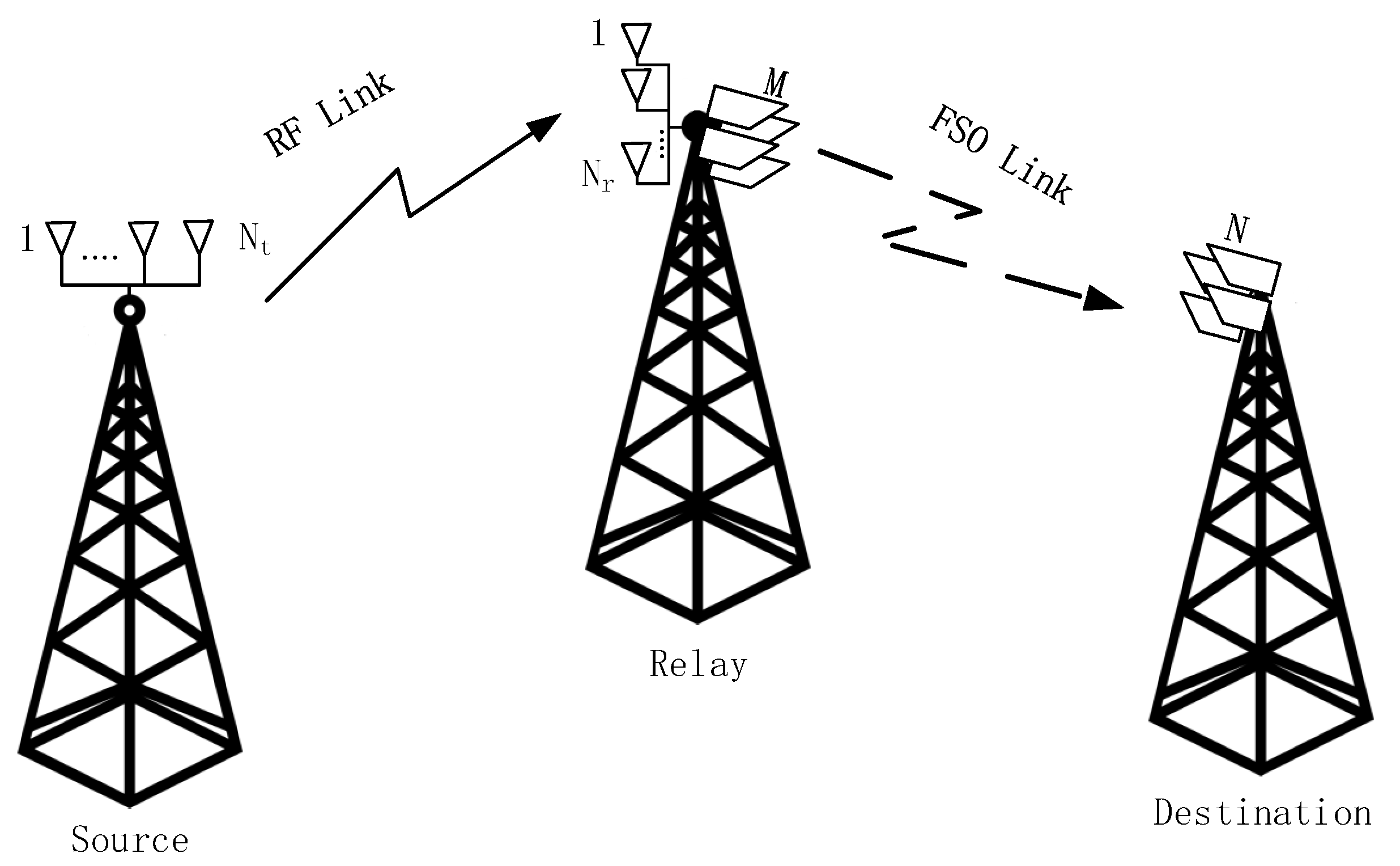
The block diagram of the system is shown in Figure 1. The channel from source to relay link is Rayleigh distributed and the FSO link is characterized by Gamma–Gamma ( ΓΓ ) turbulence. The system uses DF relay to convert electrical signals to optical signals.
For the RF link, it consists of N t transmitting antennas and N r antennas for reception. Binary phase shift keying (BPSK) modulation is adopted in the RF link. The received signal vector can be expressed as Y = Hx + n . where H = h 11 h 1 N t h N r 1 h N r N t is the channel coefficients matrix, which consists of N t × N r statistically independent elements. n is the noise vector, which is assumed to be Additive White Gaussian Noise (AWGN). This link is assumed to be characterized by Rayleigh fading. x = c v T = c v 1 v N r T is the transmitted signal vector. c is the transmitted symbol and v is the transmit weighting vector. The source to relay MIMO RF link adopts the maximal ratio transmission (MRT) [11]. At the relay, the corresponding CDF of γ R F is
F γ R F γ = 1 exp γ γ ¯ R F u = 0 N t N r 1 1 u ! γ γ ¯ R F u .
We adopt a DF relaying based system. The relay decodes the received RF signal and modulates the signal into an optical signal. For the FSO link, we assumed that the relay is equipped M photo aperture transmitters and the destination is equipped with N photodetectors. The transmitter adopts repetition coding (RC), and an equal gain combining (EGC) technique is employed at the receiver. The relay node uses the subcarrier intensity modulation (SIM) technique for converting the input signal into the optical signal [12]. A DC bias is added to the optical signal by the laser diode to avoid the negative valued signal. At the receiver, the DC bias is filtered out. We assume that the distance of photodetectors is greater than the coherence distance to ensure that the received signals are uncorrelated.
First, we consider the case where the pointing error is not negligible. The received signal at the j = 1 , , N th antenna can be expressed as:
y j = η i = 1 M I i , j x + n j
where η denotes the optical–to–electrical conversion efficiency, x denotes the transmitted signal and n j is the Additive White Gaussian Noise (AWGN) with zero mean and variance σ 2 . Let E x 2 = E x , using the equal gain combining (EGC) technique, the total received SNR can be expressed as:
γ = η 2 E x i = 1 M j = 1 N I i , j 2 M 2 N 2 σ 2 = γ ¯ i = 1 M j = 1 N I i , j 2 M 2 N 2 = γ ¯ M 2 N 2 I T 2
where, the average SNR is defined as γ ¯ = η 2 E x σ 2 , and I T = i = 1 M j = 1 N I i , j .
For the pointing errors, the independent identical Gaussian distributions for the elevation and the horizontal displacement (sway) are considered. The PDF of the pointing error existing on the i–th transmitting antenna received by the j–th receiving antenna is given by:
f h i , j p = ϕ 2 A 0 ϕ 2 h i , j p ϕ 2 1 , 0 h i , j p A 0
where ϕ = ω z e q 2 σ s is the ratio between the equivalent beam radius ω z e q at the receiver and the pointing error displacement standard deviation σ s (jitter) at the receiver. A 0 = e r f v 2 denotes the fraction of the collected power at r = 0 , v = π R a / 2 w z , w z is the beam waist, R a denotes the aperture radius of the receiver. ω z e q = ω z 2 π e r f ( v ) / 2 v exp ( v 2 ) represents the equivalent beam waist.
Reference [13] proposed a new method to approximate the distribution for the sum of L ΓΓ fading with Rayleigh pointing error random variables, the PDF is shown as following:
f y y n = 0 i = 0 n Λ v , n , i 2 L g α s β s + 1 Γ α s Γ β s L L g L α s β s A 0 ω L g 2 y L g 2 1 × G L , L + 1 L + 1 , 0 2 α s β s A 0 ω y 2 β s + i L g , 0 , , 0 1 , 1 , , 1
where γ F S O is the instantaneous SNR of the FSO link and γ ¯ F S O is the average SNR of the FSO link. α s = M N α + ε β s = M N β , g = 2 ϕ 2 denotes the parameter related to misalignment. The parameters α and β are given by [14]
α = exp ( 0.49 σ R 2 ( 1 + 1.11 σ R 12 / 5 ) 7 / 6 ) 1 1 , β = exp ( 0.51 σ R 2 ( 1 + 0.69 σ R 12 / 5 ) 5 / 6 ) 1 1 ,
where σ R 2 is the Rytov variance, which is given by σ R 2 = 1.23 C n 2 ( 2 π λ F S O ) 7 6 L 11 6 . C n 2 is the refractive index. ε is adjustment parameter, which is given by ε = ( M N 1 ) × ( −0.127−0.95 α 0.0058 β )/ 1 + 0.00124 α + 0.98 β . Γ ( · ) is the Gamma function, G - , - - , - - is Meijer’s G-function, and, L = M N . The coefficient Λ v , n , i = 1 i π Γ 2 v Γ 1 2 + n v L n , i 2 v i Γ 1 2 v Γ 1 2 + n + v n ! , v = α s β s is the order of the modified Bessel function of the second kind. L n , i is Lah numbers [15] and it is defined as L n , i = n 1 i 1 n ! i ! , for n, i > 0. The correcting factor F is defined as F = 2 + g L L L L g L 1 2 + g .
According to the distribution theorem of the random variable function, the PDF of the γ F S O can be expressed as:
f F S O p γ F S O = d d γ F S O M N F γ F S O γ ¯ F S O f y M N F γ F S O γ ¯ F S O
Then, substitute Equation (7) into Equation (5), the following expression can be obtained:
f F S O p γ = n = 0 i = 0 n Λ v , n , i 2 L g α s β s + 1 Γ α s Γ β s L L g L α s β s A 0 ω M N F L g 2 1 γ ¯ L g 4 γ L g 4 1 × G L , L + 1 L + 1 , 0 2 α s β s A 0 ω M N F γ γ ¯ 2 m + i L g , 0 , , 0 1 , 1 , , 1
Using ([16] [Equation (07.34.21.0084.01)]), we can get:
F F S O p γ t h = 0 γ t h f γ γ = n = 0 i = 0 n Λ v , n , i 2 3 β s + 2 i L g 2 L α s 1 2 π 3 / 2 Γ α s Γ β s L L g L α s β s A 0 ω M N F L g 2 γ t h γ ¯ L g 4 G 4 L + 1 , 4 L + 5 4 L + 4 , 1 1 16 α s β s A 0 ω M N F 2 γ t h γ ¯ 2 β s + i L g 4 , 2 β s + i L g + 1 4 , 2 β s + i L g + 2 4 , 2 β s + i L g + 3 4 , 0 , 1 4 , 2 4 , 3 4 L , L g 4 1 L g 4 , 1 4 , 2 4 , 3 4 , 4 4 L
where symbol L denotes the L times repetition of a given tuple.
Further, we use ([16] [Equation (07.34.17.0011.01)]) to simplify the expression. Finally, we get CDF of γ F S O as the following:
F F S O p γ t h = n = 0 i = 0 n Λ v , n , i 2 3 β s + 2 i L g 2 L α s 1 2 π 3 / 2 Γ α s Γ β s L L g L G 4 L + 1 , 4 L + 5 4 L + 4 , 1 1 16 α s β s A 0 ω M N F 2 γ t h γ ¯ 2 β s + i 4 , 2 β s + i + 1 4 , 2 β s + i + 2 4 , 2 β s + i + 3 4 , Lg 4 , 1 + Lg 4 , 2 + Lg 4 , 3 + Lg 4 L , 0 1 , 1 + Lg 4 2 + Lg 4 , 3 + Lg 4 , 4 + Lg 4 L
Due to the complicated form of the above formulas, in order to analyze the main determinants of the approximate performance of the entire system under the high SNR region, we have considered the case where the pointing error can be neglected in the following analysis.
When the pointing error can be neglected, that is to say A 0 = 1 , g , we assume the link of MIMO FSO is characterized by ΓΓ turbulence. Considering the complexity of the calculation, we simplify the system model. We currently do not consider the impact of misalignment on the system. For MN statistically independent and identically distributed ΓΓ random variables, the probability density function (PDF) is as follows [17]
f F S O ( γ F S O ) = ( α s β s ) ( α s + β s ) / 2 γ F S O [ ( α s + β s ) / 4 1 ] 2 h a ( α s + β s ) / 2 γ ¯ F S O ( α s + β s ) / 4 Γ ( α s ) Γ ( β s ) × G 0 , 2 2 , 0 α s β s h a γ F S O γ ¯ F S O , α s β s 2 , β s α s 2 ,
We can derive the CDF of the γ F S O as
F F S O ( γ F S O ) = 2 α s + β s 2 π Γ ( α s ) Γ ( β s ) G 1 , 5 4 , 1 α s β s 2 16 γ F S O γ ¯ F S O 1 Δ 1 , 0 ,
where Δ 1 = α s 2 , α s + 1 2 , β s 2 , β s + 1 2 .

3. Outage Probability

Outage probability is a very important factor in the wireless communication system, which is defined as when the system’s instantaneous SNR drops below a certain threshold γ t h . We investigate the OP of asymmetric dual–hop MIMO mixed RF/FSO DF relaying system. The end–to–end SNR outage probability of the system can be expressed as [18]
P o u t = Pr γ e q < γ t h = Pr min γ R F , γ F S O < γ t h = F γ R F ( γ t h ) + F F S O ( γ t h ) F γ R F ( γ t h ) F F S O ( γ t h ) .
Then, substituting the CDF of γ R F and γ F S O from Equations (1) and (12), respectively, after some mathematical simplification, the closed form of OP can be obtained as
P o u t = 1 + exp γ t h γ ¯ R F u = 0 N t N r 1 1 u ! γ t h γ ¯ R F u × 2 α s + β s 2 π Γ ( α s ) Γ ( β s ) G 1 , 5 4 , 1 α s β s 2 16 γ t h γ ¯ F S O 1 Δ 1 , 0 1 .
Similarly, we can get the OP of the system considering the pointing error by replacing F F S O ( γ t h ) with F F S O p γ t h .

4. Error Performance

In this section, the closed form expression for a bit error rate of a asymmetric dual–hop MIMO mixed RF/FSO DF relaying system is derived. We use the unified expression of binary modulation schemes BER in [19]
P e ¯ = q p 2 Γ ( p ) 0 e q γ e q γ e q p 1 F γ min ( γ e q ) d γ e q ,
where p = 0.5, q = 1 for BPSK modulation schemes. Other modulation scheme parameters are available in Reference [20]. Substituting Equation (14) into Equation (15), we obtian
P e ¯ = q p 2 Γ ( p ) 0 e q γ e q γ e q p 1 F γ R F ( γ e q ) d γ e q + q p 2 Γ ( p ) 0 e q γ e q γ e q p 1 F F S O ( γ e q ) d γ e q q p 2 Γ ( p ) 0 e q γ e q γ e q p 1 F γ R F ( γ e q ) F F S O ( γ e q ) d γ e q = I 1 + I 2 I 3 .
For easy calculation, we split this formula into three parts, where integrals are defined and solved as follows
I 1 = q p 2 Γ ( p ) 0 e q γ e q γ e q p 1 F γ R F ( γ e q ) d γ e q = 1 2 q p 2 Γ ( p ) u = 0 N t N r 1 1 u ! 1 γ ¯ R F u Γ u + p q + 1 γ ¯ R F u + p .
Using ([16] [Equation (07.34.21.0088.01)])
I 2 = q p 2 Γ ( p ) 0 e q x x p 1 F F S O ( x ) d x = 2 α s + β s 3 π Γ ( α s ) Γ ( β s ) Γ ( p ) G 2 , 5 4 , 2 α s β s 2 16 q γ ¯ F S O 1 p , 1 Δ 1 , 0 ,
I 3 = q p 2 Γ ( p ) 0 e q x x p 1 F γ R F ( x ) F F S O ( x ) d x = I 2 q p Γ ( p ) 2 α s + β s 3 π Γ ( α s ) Γ ( β s ) u = 0 N t N r 1 1 u ! 1 γ ¯ R F u q γ ¯ R F + 1 γ ¯ R F u + p × G 2 , 6 4 , 2 α s β s 2 16 q + 1 γ ¯ R F γ ¯ F S O 1 p u , 1 Δ 1 , 0 .
Then, substituting the expression for I 1 , I 2 , and I 3 from Equations (17)–(19), respectively. After some mathematical simplification, the closed form of BER is available as follows
P e ¯ = 1 2 q p 2 Γ ( p ) u = 0 N t N r 1 1 u ! 1 γ ¯ R F u Γ u + p q + 1 γ ¯ R F u + p 1 2 α s + β s 2 π Γ ( α s ) Γ ( β s ) Γ u + p × G 2 , 6 4 , 2 α s β s 2 16 q + 1 γ ¯ R F γ ¯ F S O 1 p u , 1 Δ 1 , 0 .

5. Ergodic Capacity

Apart from the OP and BER performance, the average channel ergodic capacity is another important metric of wireless communication systems. In this section, we discuss the ergodic capacity of the considered asymmetric dual–hop MIMO mixed RF/FSO DF relaying system. The ergodic channel capacity is defined as [21] C ¯ = E 1 2 log 2 ( 1 + ω ¯ γ e q ) where ω ¯ = 1 for heterodyne detection [22].
From [23], we can calculate average capacity in terms of the complementary cumulative distribution function (CCDF) of γ e q as
C ¯ = ω ¯ 2 ln ( 2 ) 0 ( 1 + ω ¯ γ e q ) 1 F ¯ γ ( γ e q ) d γ e q ,
where F ¯ γ ( γ e q ) = 1 F γ ( γ e q ) .
Utilizing this ([16] [Equation (01.02.26.0005.01)]) by expressing the identity as ( 1 + ω ¯ γ e q ) 1 = G 1 , 1 1 , 1 ω ¯ γ e q 0 0 = G 5 and we define G 1 = G 1 , 5 4 , 1 α s β s 2 16 γ F S O γ ¯ F S O 1 Δ 1 , 0 .
Then we can calculate the channel capacity by calculating the two integrals separately as follows
C ¯ = ω ¯ 2 ln ( 2 ) 0 G 5 exp γ γ ¯ R F u = 0 N t N r 1 1 u ! γ γ ¯ R F u exp γ γ ¯ R F u = 0 N t N r 1 1 u ! γ γ ¯ R F u 2 α s + β s 2 π Γ ( α s ) Γ ( β s ) G 5 G 1 d γ = I 4 I 5 ,
where we can calculate I 4 as
I 4 = ω ¯ 2 ln ( 2 ) 0 G 5 exp γ γ ¯ R F u = 0 N t N r 1 1 u ! γ γ ¯ R F u d γ = ω ¯ 2 ln ( 2 ) u = 0 N t N r 1 1 u ! 1 γ ¯ R F u γ ¯ R F u + 1 G 2 , 1 1 , 2 ω ¯ γ ¯ R F u , 0 0 .
The product of the two independent Meijer G–functions, which can be expressed in terms of extended generalized bivariate Meijer G-function (EGBMGF) ([16] [Equation (07.34.16.0003.01)]) is used to calculate I 5
I 5 = ω ¯ 2 ln ( 2 ) 0 e γ γ ¯ R F u = 0 N t N r 1 1 u ! γ γ ¯ R F u 2 α s + β s 2 π Γ ( α s ) Γ ( β s ) G 5 G 1 d γ = ω ¯ 2 ln ( 2 ) 2 α s + β s 2 π Γ ( α s ) Γ ( β s ) u = 0 N t N r 1 1 u ! 1 γ ¯ R F u γ ¯ R F u + 1 S ω ¯ γ ¯ R F , α s β s 2 16 γ ¯ R F γ ¯ F S O 1 , 0 0 , 0 u + 1 1 , 1 1 , 1 0 0 4 , 1 1 , 5 1 Δ 1 , 0 .
After some mathematical manipulations
C ¯ = ω ¯ 2 ln ( 2 ) u = 0 N t N r 1 1 u ! 1 γ ¯ R F u γ ¯ R F u + 1 × G 2 , 1 1 , 2 ω ¯ γ ¯ R F u , 0 0 2 α s + β s 2 π Γ ( α s ) Γ ( β s ) × S ω ¯ γ ¯ R F , α s β s 2 16 γ ¯ R F γ ¯ F S O 1 , 0 0 , 0 u + 1 1 , 1 1 , 1 0 0 4 , 1 1 , 5 1 Δ 1 , 0 .

6. Asymptotic Performance Analysis

In order to analyze the diversity order of the considered asymmetric dual–hop MIMO mixed RF/FSO DF relaying system, we need to further study the asymptotic behavior when γ ¯ R F , γ ¯ F S O .
For the RF link, the exponent function can be expanded into series form. We can rewrite the CDF of γ RF
F γ R F γ R F = exp γ R F γ ¯ R F exp γ R F γ ¯ R F u = 0 N t N r 1 1 u ! γ R F γ ¯ R F u = u = 0 1 u ! γ R F γ ¯ R F u u = N t N r 1 u ! γ R F γ ¯ R F u .
We neglect the higher order terms. The asymptotic outage probability of the RF link can be derived as
F γ R F γ N t N r ! N t N r γ γ ¯ R F N t N r .
For the FSO link, the series representation of the Meijer’s G function is given by ([16] [Equation (07.34.06.0006.01)]) into
G p , q m , n z a 1 , , a n , a n + 1 , , a p b 1 , , b m , b m + 1 , , b q = k = 1 m j = 1 , j k m Γ ( b j b k ) j = 1 n Γ ( 1 a j + b k ) j = n + 1 p Γ ( a j b k ) j = m + 1 q Γ ( 1 b j + b k ) z b k 1 + O z .
Considering that α s > β s , the asymptotic outage probability of the FSO link can be obtained as follows
F F S O ( γ F S O ) 2 α s + β s 2 π Γ ( α s ) Γ ( β s ) Γ ( α s β s 2 ) Γ ( α s β s + 1 2 ) Γ ( 1 2 ) Γ ( β s 2 ) Γ ( 1 + β s 2 ) × α s β s 4 M N β γ ¯ F S O γ F S O M N β / 2 .
The asymptotic approximation of the end–to–end OP is given by
P o u t γ ¯ R F N t N r + γ ¯ F S O M N β / 2 .
Therefore, the diversity gain of the considered asymmetric dual–hop MIMO mixed RF/FSO DF relaying system d = min N t N r , M N β / 2 .

7. Diversity-Multiplexing Tradeoff Analysis

The diversity–multiplexing tradeoff is an important performance metric for comparing and choosing different MIMO schemes. For example, when the channel conditions are poor, we can maximize the diversity gain to combat fading. On the other hand, we can maximize the multiplexing gain to increase the data rate when the channel states are good.
Outage diversity order for MIMO RF under a Rayleigh channel can be obtained as follows ([24] [(4)])
d R F r = N t r N r r , 0 r < min N t , N r .
For the MIMO FSO link, the outage diversity order under the ΓΓ channel is given as ([25] [Equation (47)])
d F S O r = M N 1 r 2 min α , β + M 1 N 1 r 2 , 0 r < 1 M r N r 2 , 1 r N .
Refer to ([26] [Equation (6)]), the diversity–multiplexing tradeoff of the considered asymmetric dual–hop MIMO mixed RF/FSO DF single-relaying system can be derived as follows
d r = min d R F r d F S O r , 0 r < min N t , N r , M , N .

8. Numerical Simulation and Discussion

In this section, numerical simulation of the considered asymmetric dual–hop MIMO mixed RF/FSO DF single relaying system’s OP, BER, and capacity are presented, respectively. For the MIMO RF link, the system transmitter and receiver’s number are N t = 2 , N r 2 , 3 . For the MIMO FSO link, laser wavelength λ = 1550 nm , transmitter and receiver’s number M 1 , 2 , N 1 , 2 , 3 , 4 , 6 , outer scale α = 4.3407 , inner scale β = 1.3088 . For the number of series expansion terms considering the pointing error, we assume J = 20 is accurate enough for our simulation channel conditions.
Figure 2 illustrates the outage probability of the MIMO mixed RF/FSO system with pointing error in the case of different optical antennas. Where w s / R a = 3 , σ s / R a = 1 . γ t h = 10 dB. It can be seen from the figure that even in the presence of pointing errors, the outage probability of the system decreases as the number of optical antennas increases. For example, the outage probability of N t , N r , M , N = 2 , 3 , 2 , 3 scheme yield 4.854 × 10 3 when the SNR is 40 dB; while N t , N r , M , N = 2 , 3 , 1 , 1 only yields 0.1957.
Figure 3 presents the outage probability of the MIMO mixed RF/FSO system under the different pointing error influence. The simulation parameters are as follows N t , N r , M , N = 2 , 3 , 2 , 2 , w s / R a = 8 , γ t h = 10 dB. It can be observed that the outage probability is greatly affected by the pointing error. The severity degree of the pointing errors increases as the value of σ s / R a increases, and the outage probability also increases. For example, the outage probability of the system achieves 5.394 × 10 2 when the average SNR is 50 dB and σ s / R a = 1 , while the system achieves 0.3767 when σ s / R a = 4 .
Figure 4 is a plot of outage probability of the considered MIMO mixed RF/FSO system without pointing error when γ t h = 5 dB. We assume that the average SNRs of each link are the same. As can be seen, the system’s diversity order mainly depends on the minimum diversity order of each link. For example, when N t , N r , M , N = 2 , 2 , 1 , 1 , the slope of the OP curve is β / 2 , which means the diversity order depends on the FSO link. On the other hand, when N t , N r , M , N = 2 , 2 , 4 , 4 , the slope of the OP curve is 4 , which means the diversity order depends on the RF link.
Figure 5 illustrates the bit error rate (BER) performance of the considered MIMO mixed RF/FSO system without pointing error vs. average SNR per hop. As seen, the system performance improves when the number of antennas is increased, since this also increases the performance against fading and reduces the decoding error at the relay. We can also see the same characteristics as the OP performance and the end–to–end diversity gain is determined by the minimum diversity gain of each hop. Therefore, in different scenarios, we can flexibly combine the number of source, relay, and receiver antennas to obtain the same diversity gain; for example, when the complexity of the relay is limited, we can reduce the number of the relay’s antennas and increase the number of antennas at the source and receiver to obtain the same diversity gain.
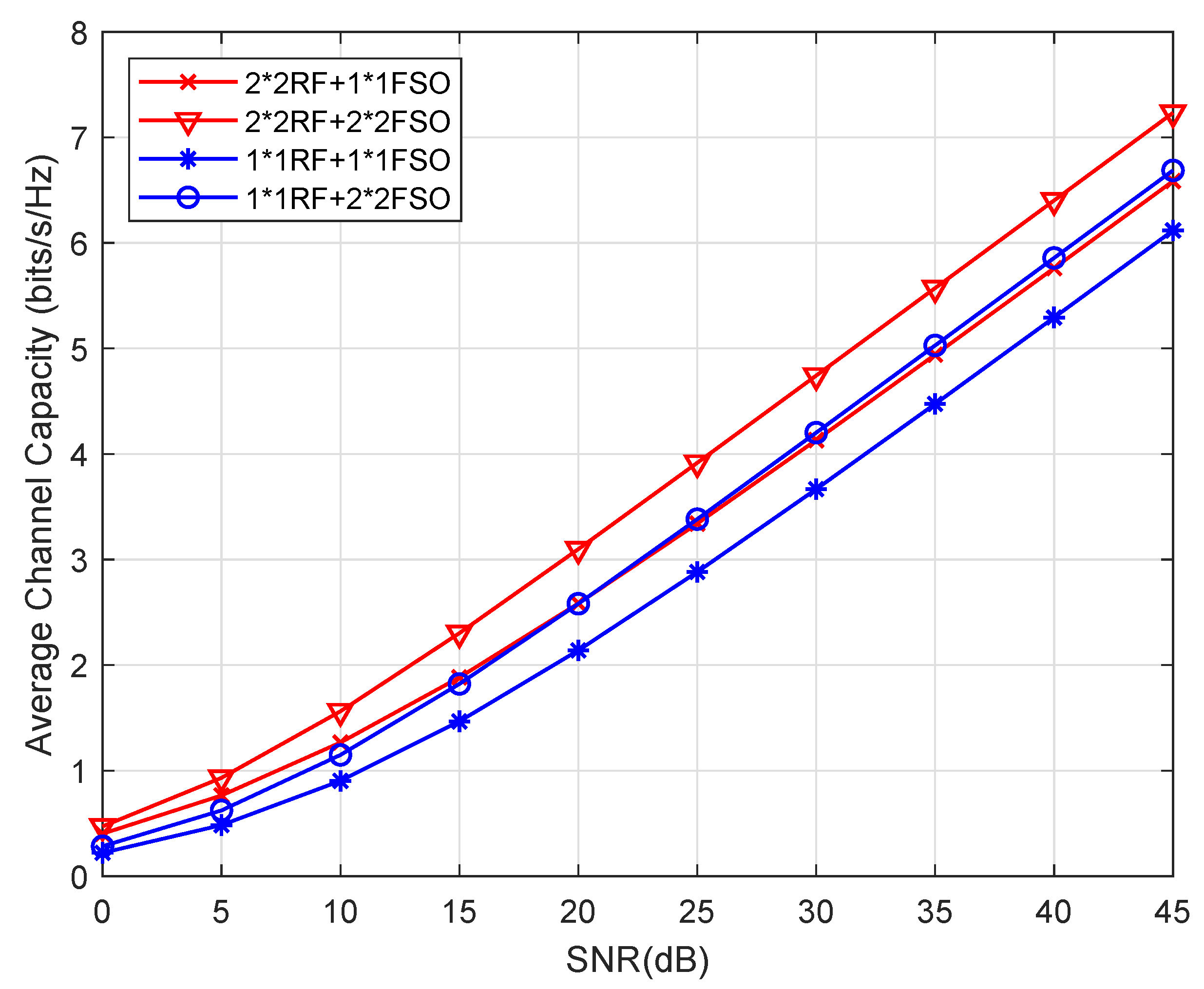
Figure 6 presents a comparison of the average ergodic capacity of different schemes of MIMO mixed RF/FSO systems without pointing error. It can be seen that the MIMO system can significantly increase the system’s end–to–end channel capacity compared with the SISO system. For instance, the ergodic capacity of the system of N t , N r , M , N = 1 , 1 , 1 , 1 is 6.12 bits/s/Hz at the SNR of 45dB. While the ergodic capacity of the system of N t , N r , M , N = 2 , 2 , 2 , 2 is increased to 7.23 bits/s/Hz.
Figure 7 shows the diversity–multiplexing tradeoff of the considered MIMO mixed RF/FSO system and SIMO RF/MIMO FSO relay system. Compared with the SIMO RF/MIMO FSO relay system, the MIMO system considered in this paper has obvious advantages in diversity gain and multiplexing gain, as shown in the figure. In particular, the end–to–end maximal diversity gain of the system is min N t N r , M N 2 min α , β , and the maximal multiplexing gain is min N t , N r , M , N . We can flexibly allocate diversity or multiplexing gain through different coding methods under different fading conditions. For example, we can use Vertical Bell Labs Layered Space–Time (V–BLAST) encoding to obtain a higher transmission code rate when the channel condition is good. On the other hand, we can use RC to combat channel fading when the channel condition is poor.
Figure 8 presents diversity–multiplexing tradeoff (DMT) curves of different number MIMO antennas configurations of RF links and FSO links, respectively. From the figure we can find that DMT curves of FSO links are always lower than the curves of RF links under the same configuration. The reason is that the channel of the FSO link using the IM/DD method only provides one degree of freedom. While the RF channel provides complex–valued channel coefficients, which has two degrees of freedom, this greatly affects the diversity gain. Further, we find that there is an intersection point between a (3 × 4) RF curve and (4 × 4) FSO curve, which means that the end–to–end maximal diversity gain is determined by the FSO link and end–to–end maximal multiplexing gain is determined by the RF link, respectively. It is obvious that as the number of antennas increases, both maximal diversity gain and maximal multiplexing gain increases.
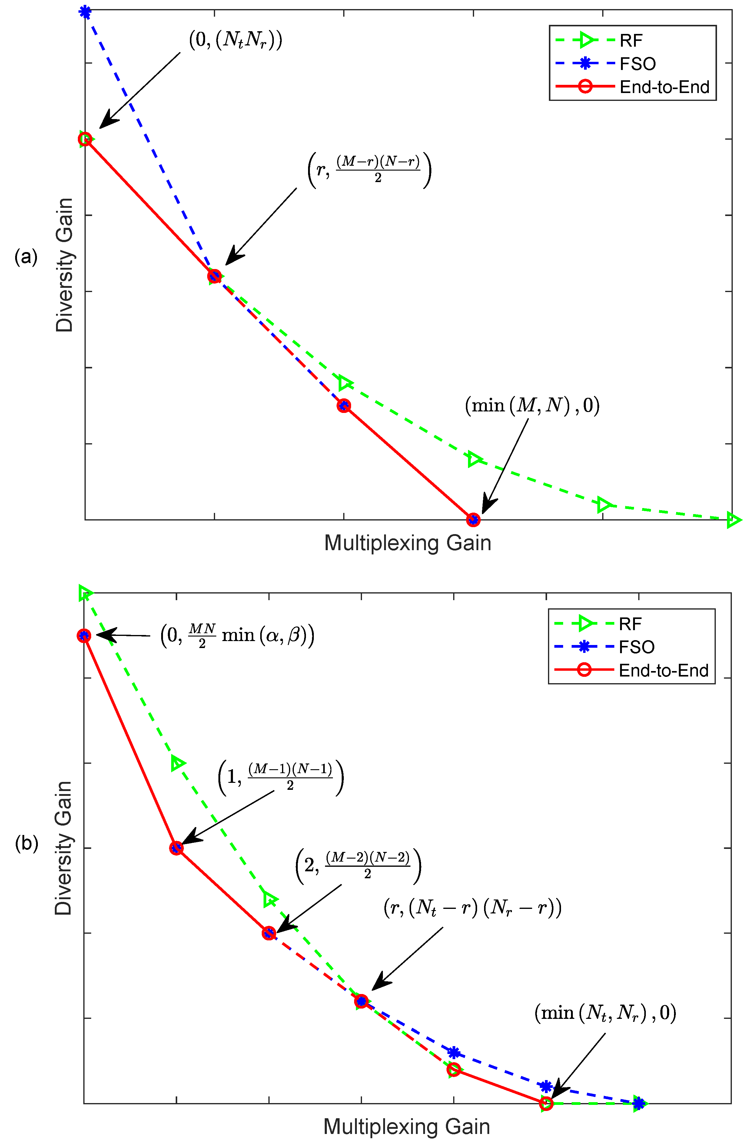
Figure 9 presents the DMT of the MIMO mixed RF/FSO system with an intersection under different conditions. Similar to Figure 8, we consider the universal case of intersection under the system we considered. Since the DMT curves of RF and FSO are both decreasing, consider the following two situations, (1) N t N r < M N 2 min α , β min N t , N r > min M , N and (2) N t N r > M N 2 min α , β min N t , N r < min M , N , then the two curves have at least one intersection as shown in Figure 9a,b respectively. Figure 9a shows that maximal diversity gain depends on the RF link under situation (1). While maximal diversity gain depends on the FSO link under situation (2), as shown in Figure 9b. While the maximal multiplexing gain dependence is opposite.

9. Conclusions

In this paper, we investigated the performance of the asymmetric dual–hop MIMO mixed RF/FSO DF relaying system, where the RF link suffers from Rayleigh fading and the MIMO FSO link suffered from GG distributed turbulence. For the considered system, we derived the closed form expressions of the system outage probability, BER, and average ergodic capacity. The approximate expression of the system outage probability considering the pointing error is also derived. In addition, the analysis of asymptotic performance and diversity–multiplexing tradeoff was given to provide deeper insight of the system characteristics. We found that the end-to-end diversity gain was mainly determined by the minimum diversity gain of each hop, and the maximal multiplexing gain was dependent on the minimum number of antennas in each link. The model studied in this paper has the characteristics of excellent error performance, high energy efficiency, and strong robustness, attracting attention as an effective solution for future large–capacity and high–speed communication systems.

Author Contributions

Conceptualization, H.L.; funding acquisition, X.L.; methodology, H.L.; writing—original draft preparation, H.L.; writing—review and editing, H.L., Y.L., C.G. and M.M. All authors have read and agreed to the published version of the manuscript.

Funding

The APC was funded by Xiaofeng Li.

Institutional Review Board Statement

Not applicable.

Informed Consent Statement

Not applicable.

Acknowledgments

This project has received funding from the European Union’s Horizon 2020 research and innovation programme under the Marie Skłodowska–Curie grant agreement No 713694.

Conflicts of Interest

The authors declare no conflict of interest.

References

  1. Anees, S.; Bhatnagar, M.R. Performance of an Amplify-and-Forward Dual-Hop Asymmetric RF/FSO Communication System. J. Opt. Commun. Netw. 2015, 7, 124. [Google Scholar] [CrossRef]
  2. Lee, E.; Park, J.; Han, D.; Yoon, G. Performance Analysis of the Asymmetric Dual-Hop Relay Transmission With Mixed RF/FSO Links. IEEE Photon. Technol. Lett. 2011, 23, 1642–1644. [Google Scholar] [CrossRef]
  3. Kaushal, H.; Kaddoum, G. Optical Communication in Space: Challenges and Mitigation Techniques. IEEE Commun. Surveys Tuts. 2017, 19, 57–96. [Google Scholar] [CrossRef] [Green Version]
  4. Bhatnagar, M.R.; Ghassemlooy, Z. Performance Analysis of Gamma—Gamma Fading FSO MIMO Links with Pointing Errors. J. Lightw. Technol. 2016, 34, 2158–2169. [Google Scholar] [CrossRef]
  5. Molisch, A.F. Wireless Communications, 2nd ed.; John Wiley and Sons Ltd.: Hoboken, NJ, USA, 2011. [Google Scholar]
  6. Zedini, E.; Ansari, I.S.; Alouini, M.S. Performance Analysis of Mixed Nakagami-m and Gamma-Gamma Dual-Hop FSO Transmission Systems. IEEE Photonics J. 2015, 7, 1–20. [Google Scholar] [CrossRef] [Green Version]
  7. Chen, L.; Wang, W. Multi-diversity combining and selection for relay-assisted mixed RF/FSO system. Opt. Commun. 2017, 405, 1–7. [Google Scholar] [CrossRef]
  8. Yang, L.; Hasna, M.O.; Gao, X. Performance of Mixed RF/FSO with Variable Gain over Generalized Atmospheric Turbulence Channels. IEEE J. Sel. Areas Commun. 2015, 33, 1913–1924. [Google Scholar] [CrossRef]
  9. Varshney, N.; Puri, P. Performance Analysis of Decode-and-Forward Based Mixed MIMO-RF/FSO Cooperative Systems with Source Mobility and Imperfect CSI. J. Lightw. Technol. 2017, 35, 2070–2077. [Google Scholar] [CrossRef]
  10. Liang, H.; Gao, C.; Li, Y.; Miao, M.; Li, X. Performance analysis of mixed MISO RF/SIMO FSO relaying systems. Opt. Commun. 2021, 478, 126344. [Google Scholar] [CrossRef]
  11. Lo, T.K.Y. Maximum ratio transmission. IEEE Trans. Commun. 1999, 47, 1458–1461. [Google Scholar] [CrossRef]
  12. Huang, W.; Takayanagi, J.; Sakanaka, T.; Nakagawa, M. Atmospheric optical communication system using subcarrier PSK modulation. In Proceedings of the ICC ’93—IEEE International Conference on Communications, Geneva, Switzerland, 23–26 May 1993; Volume 3, pp. 1597–1601. [Google Scholar]
  13. Miao, M.; Li, X. Novel approximate distribution of the sum of Gamma—Gamma variates with pointing errors and applications in MIMO FSO links. Opt. Commun. 2021, 486, 126780. [Google Scholar] [CrossRef]
  14. Andrews, L.C.; Phillips, R.L.; Hopen, C.Y. Laser Beam Scintillation with Applications, 1st ed.; SPIE Press: Bellingham, WA, USA, 2001. [Google Scholar]
  15. Comtet, L. Advanced Combinatorics:The Art of Finite and Infinite Expansions, 1st ed.; Springer: Dordrecht, The Netherlands, 1974. [Google Scholar]
  16. Mathematics. Meijer G-Functions. 1998. Available online: http://functions.wolfram.com/HypergeometricFunctions/MeijerG/ (accessed on 12 July 2020).
  17. Han, L.; Jiang, H.; You, Y.; Ghassemlooy, Z. On the performance of a mixed RF/MIMO FSO variable gain dual-hop transmission system. Opt. Commun. 2018, 420, 59–64. [Google Scholar] [CrossRef] [Green Version]
  18. Varshney, N.; Jagannatham, A.K. Cognitive Decode-and-Forward MIMO-RF/FSO Cooperative Relay Networks. IEEE Commun. Lett. 2017, 21, 893–896. [Google Scholar] [CrossRef]
  19. Ansari, I.S.; Al-Ahmadi, S.; Yilmaz, F.; Alouini, M.S.; Yanikomeroglu, H. A New Formula for the BER of Binary Modulations with Dual-Branch Selection over Generalized-K Composite Fading Channels. IEEE Trans. Commun. Technol. 2011, 59, 2654–2658. [Google Scholar] [CrossRef] [Green Version]
  20. Sagias, N.C.; Zogas, D.A.; Karagiannidis, G.K. Selection diversity receivers over nonidentical Weibull fading channels. IEEE Trans. Veh. Technol. 2006, 54, 2146–2151. [Google Scholar] [CrossRef] [Green Version]
  21. Gu, Y.; Aissa, S. RF-based Energy Harvesting in Decode-and-Forward Relaying Systems: Ergodic and Outage Capacities. IEEE Trans. Wireless Commun. 2018, 14, 6425–6434. [Google Scholar] [CrossRef]
  22. Petkovic, M.I.; Ansari, I.S.; Djordjevic, G.T.; Qaraqe, K.A. Error rate and ergodic capacity of RF-FSO system with partial relay selection in the presence of pointing errors. Opt. Commun. 2019, 438, 118–125. [Google Scholar] [CrossRef] [Green Version]
  23. Annamalai, A.; Palat, R.C.; Matyjas, J. Estimating ergodic capacity of cooperative analog relaying under different adaptive source transmission techniques. In Proceedings of the 2010 IEEE Sarnoff Symposium, Princeton, NJ, USA, 12–14 April 2010; pp. 1–5. [Google Scholar]
  24. Zheng, L.; Tse, D.N.C. Diversity and multiplexing: A fundamental tradeoff in multiple-antenna channels. IEEE Trans. Inf. Theory 2003, 49, 1073–1096. [Google Scholar] [CrossRef] [Green Version]
  25. Jaiswal, A.; Bhatnagar, M.R. Free-Space Optical Communication: A Diversity-Multiplexing Tradeoff Perspective. IEEE Trans. Inf. Theory 2019, 65, 1113–1125. [Google Scholar] [CrossRef]
  26. Loyka, S.; Levin, G. Diversity-multiplexing tradeoff in MIMO relay channels for a broad class of fading distributions. IEEE Commun. Lett. 2010, 14, 327–329. [Google Scholar] [CrossRef] [Green Version]
Figure 1. Block diagram of the MIMO mixed RF/FSO relaying system.
Applsci 11 03054 g001
Figure 2. Outage probability of different scheme MIMO mixed RF/FSO systems with pointing error.
Applsci 11 03054 g002
Figure 3. Outage probability of MIMO mixed RF/FSO system with different pointing error.
Applsci 11 03054 g003
Figure 4. Outage probability of different scheme MIMO mixed RF/FSO system.
Applsci 11 03054 g004
Figure 5. BER of MIMO mixed RF/FSO system.
Applsci 11 03054 g005
Figure 6. Average ergodic capacity of different schemes of MIMO mixed RF/FSO systems.
Applsci 11 03054 g006
Figure 7. Diversity–multiplexing tradeoff of MIMO mixed RF/FSO system and single input multiple output (SIMO) RF/MIMO FSO system.
Applsci 11 03054 g007
Figure 8. DMT of different MIMO configurations of RF link and FSO link.
Applsci 11 03054 g008
Figure 9. DMT of MIMO mixed RF/FSO system with intersection. (a) RF link dominates maximum diversity gain; (b) FSO link dominates maximum diversity gain.
Applsci 11 03054 g009
Publisher’s Note: MDPI stays neutral with regard to jurisdictional claims in published maps and institutional affiliations.

