Article

Research on a Piezoelectric Pump with Flexible Valves

School of Mechanical and Electrical Engineering, Guangzhou University, Guangzhou 510006, China
*
Author to whom correspondence should be addressed.
Appl. Sci. 2021, 11(7), 2909; https://doi.org/10.3390/app11072909
Submission received: 28 December 2020 / Revised: 14 March 2021 / Accepted: 17 March 2021 / Published: 24 March 2021

Abstract

:
Imitating the structure of the venous valve and its characteristics of passive opening and closing with changes in heart pressure, a piezoelectric pump with flexible valves (PPFV) was designed. Firstly, the structure and the working principle of the PPFV were introduced. Then, the flexible valve, the main functional component of the pump, was analyzed theoretically. Finally, an experimental prototype was manufactured and its performance was tested. The research proves that the PPFV can achieve a smooth transition between valved and valveless by only changing the driving signal of the piezoelectric (PZT) vibrator. The results demonstrate that when the driving voltage is 100 V and the frequency is 25 Hz, the experimental flow rate of the PPFV is about 119.61 mL/min, and the output pressure is about 6.16 kPa. This kind of pump can realize the reciprocal conversion of a large flow rate, high output pressure, and a small flow rate, low output pressure under the electronic control signal. Therefore, it can be utilized for fluid transport and pressure transmission at both the macro-level and the micro-level, which belongs to the macro–micro combined component.

1. Introduction

As an actuator, the micro-pump plays an irreplaceable role in numerous fields, such as biomedicine, aerospace, and so forth [1,2,3,4]. The reason for this is that the micro-pump has the advantages of precision for controlling flow and a compact structure. The piezoelectric (PZT) pump is a PZT-driven micro-pump. By controlling its PZT film and valve body, the fluid can be transported unidirectionally, or the flow rate and pressure of the fluid can be changed [5,6,7]. With the continuous expansion of the application of the piezoelectric pump, its taxonomy is increasing in various fields. Among them, the PZT pump can be classified according to the type of valve body; the valve body can be either a movable valve or a no-moving-part valve.
Movable valves include overall opening valves [8], cantilever valves [9], helical linear-shaped valves [10], and “E” type valves [11], and all of these can appear in valved PZT pumps. The movable valves listed above are soft structures made of rigid materials. Similarly, there are many types of no-moving-part valves, for instance, nozzle/diffuser tubes [12,13], Tesla tubes [14], spiral tubes [15], vortex diodes [16], streamlined flow tubes [17], and raindrop-shaped tubes [18], and all of these can be fitted with valveless PZT pumps. Thus, a PZT pump with a movable valve is called a “valved PZT pump”, and a PZT pump with a no-moving-part valve is called a “valveless PZT pump”. These two types of pumps have their advantages and disadvantages. In general, because of the movable parts, the valved PZT pump has a complicated structure, and the closed valve reduces the survival rate of living organisms during transport, but it can obtain a higher flow rate and back pressure. On the contrary, the structure of the valveless PZT pump is simple, and it can decrease the probability of crushing damage to the transported substance, but the flow rate is small.
In contrast to the traditionally defined valved PZT pump and the valveless PZT pump, our research group proposed a PZT pump with built-in compliant structures [19]. Based on this, the structure of the valve was improved in this study; a new type of PZT pump with flexible valves (PPFV) is proposed. The valve body of the pump imitates the structure of the venous valve and its characteristics of passive opening and closing with changes in heart pressure, which makes it set a valved state and valveless state in one. Thus, this kind of pump can realize the reciprocal conversion of the large flow rate, high pressure difference and the small flow rate, low pressure difference.

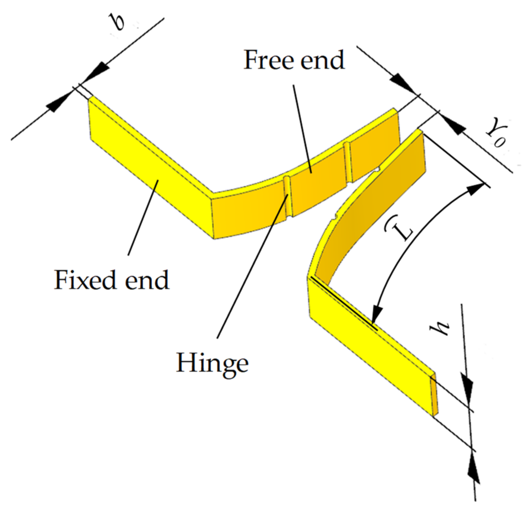
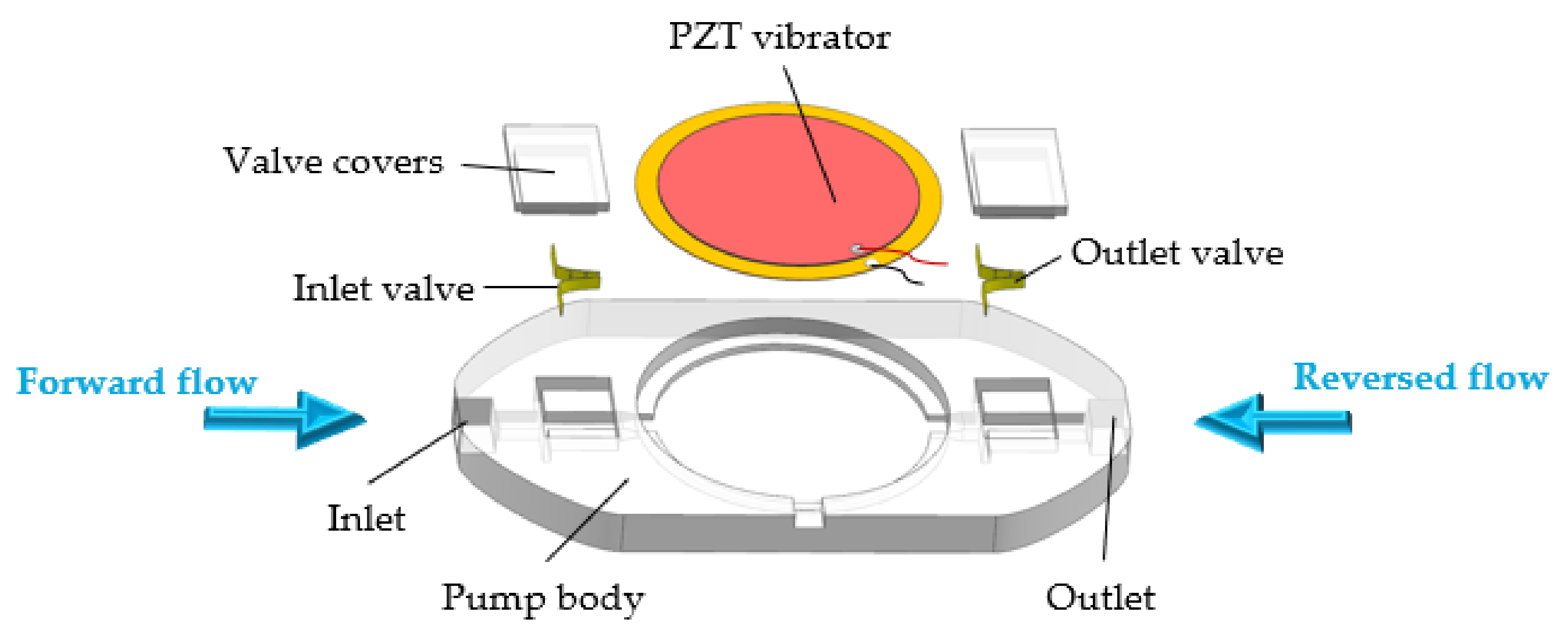
2. Structure and Working Principle

The flexible valve is a pair of curved rectangular leaflets made of elastic material, as shown in Figure 1. The leaflets contain a fixed end and a free end, and the free end is divided into three equal parts by two hinges. We marked the initial clearance of the free ends as Y0, the length of the free end as L, the height as h, and the thickness as b.
Figure 2 displays the three-dimensional model of the PPFV. The PPFV consists of a pump body, a PZT vibrator, two flexible valves, and two valve covers. The flow direction from the fixed end to the free end of the flexible valve is defined as forward, and the flow direction from the free end to the fixed end is defined as reversed. Therefore, the flexible valve installed near the inlet is the inlet valve, and the valve installed near the outlet is the outlet valve.
Under the action of an alternating current, the PZT vibrator moves up and down reciprocally. When the PZT vibrator moves from the bottom up to the highest point, the pump chamber volume expands, where there is negative pressure. Then, the fluid enters the pump chamber from the inlet valve and the outlet valve at the same time, at which time the clearance of the inlet valve increases and the clearance of the outlet valve reduces, which is called the suction stroke. Similarly, when the PZT vibrator deforms from the top to the lowest point, the pump chamber volume decreases, the pressure in the chamber increases, and the fluid is squeezed out, so the fluid is discharged from the inlet and the outlet simultaneously. At this time, the clearance of the inlet valve reduces, and the clearance of the outlet valve increases, which is called the exhaust stroke. Whether it is the suction stroke or the exhaust stroke, the flowing fluid must be in contact with the valves, generating flow resistance. During the suction stroke, the flow resistance of the outlet valve is greater than that of the inlet valve, so the quantity of fluid inhaled by the inlet valve is more than the amount of fluid inhaled by the outlet valve. Similarly, during the exhaust stroke, the flow resistance of the inlet valve is greater than the flow resistance of the outlet valve, so that the quantity of fluid discharged by the inlet valve is less than the amount of fluid discharged by the outlet valve. Therefore, the PPFV can realize one-way fluid transport macroscopically, suctioning from the inlet and discharging from the outlet.
When the amplitude of the PZT vibrator is large, the volume of the pump chamber changes greatly and the fluid flows vigorously. The flexible valve can be completely closed, thus appearing as a valved PZT pump. When the amplitude is very small, the fluid flows gently and the flexible valves do not deform. The fastigiate shape of the structure makes it resemble a valveless PZT pump with cone-shaped tubes. Consequently, the PPFV can realize the free conversion between the valved state and the valveless state.

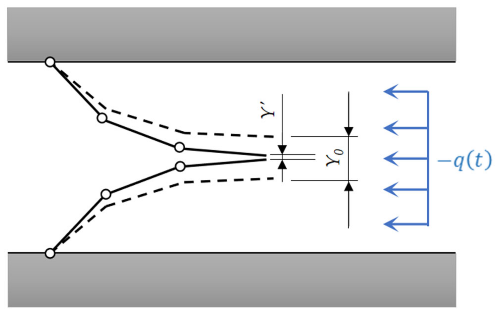
3. Theoretical Analysis

When the PZT pump works, the piezoelectric vibrator is bent up and down. The volume of the pump chamber changes periodically so that the fluid in the pump chamber moves and acts on the valves. Assuming that the flexible valves are subjected to a uniformly distributed load q t at a certain moment, the free end of the leaflet can be simplified into three continuous cantilevers, as shown in Figure 3. Combining the chain algorithm and the load increasing technique [20], the deformed clearance Y’ can be calculated, and its solution formula includes q t . The specific derivation process is in Appendix A.
When the vibrator moves to the limit position, its radial section is arched. The deformation of the middle point of the vibrator is the largest, and the amplitude of the radial points decreases with the increase of the radius r. The deformation curve ω r can be fitted by an amplitude test experiment of the vibrator. The volume changes when the pump chamber moves from the equilibrium position to the limit position can be obtained by integrating ω r , as follows:
Δ V = 2 π 0 R ω r r d r
where Δ V is the volume change quantity in a quarter period.
Whether in the valved state or the valveless state, the inlet/outlet of the PPFV corresponds to a nominal valve body. The valve body can be opened and closed by deformation, and then the fluid can be delivered in one direction. Ignoring the fluid loss caused by the gap between the flexible valve and the flow channel, for flexible valves, the deformation of the valved state is the strongest, according to Bernoulli equation, as follows:
p 1 + 1 2 ρ v 1 2 + ρ g h 1 = p 2 + 1 2 ρ v 2 2 + ρ g h 2
where h 1 = h 2 .
q ( t 0 ) = 8 ρ f 2 Δ V 2 ( 1 A 1 + 1 A 2 ) ( 1 A 1 1 A 2 )
where t0 represents the time when the PZT vibrator moves to its limit position, p 1 and p 2 are the pump chamber’s pressure and the outlet’s pressure, respectively, ρ is the density of the working medium, v 1 and v 2 are, respectively, the fluid velocity of the pump chamber and the outlet fluid velocity, h 1 and h 2 are the heights of the fluid in the pump chamber and in the outlet, respectively, f represents the driving frequency, and A 1 and A 2 respectively represent the cross-sectional area of the channel in the chamber and the cross-sectional area of the outlet channel.
According to the above calculation formulas, the deformation of the flexible valve is not only related to its structure and material parameters, but also related to the uniformly distributed load q t . The magnitude and direction of the uniformly distributed load are related to the input signal of the PZT vibrator, which mainly depends on the frequency and the voltage. Therefore, the deformation of flexible valves can be changed by controlling the input signal, and the conversion between the valved state and the valveless state can be realized.

4. Experimental Results and Discussion
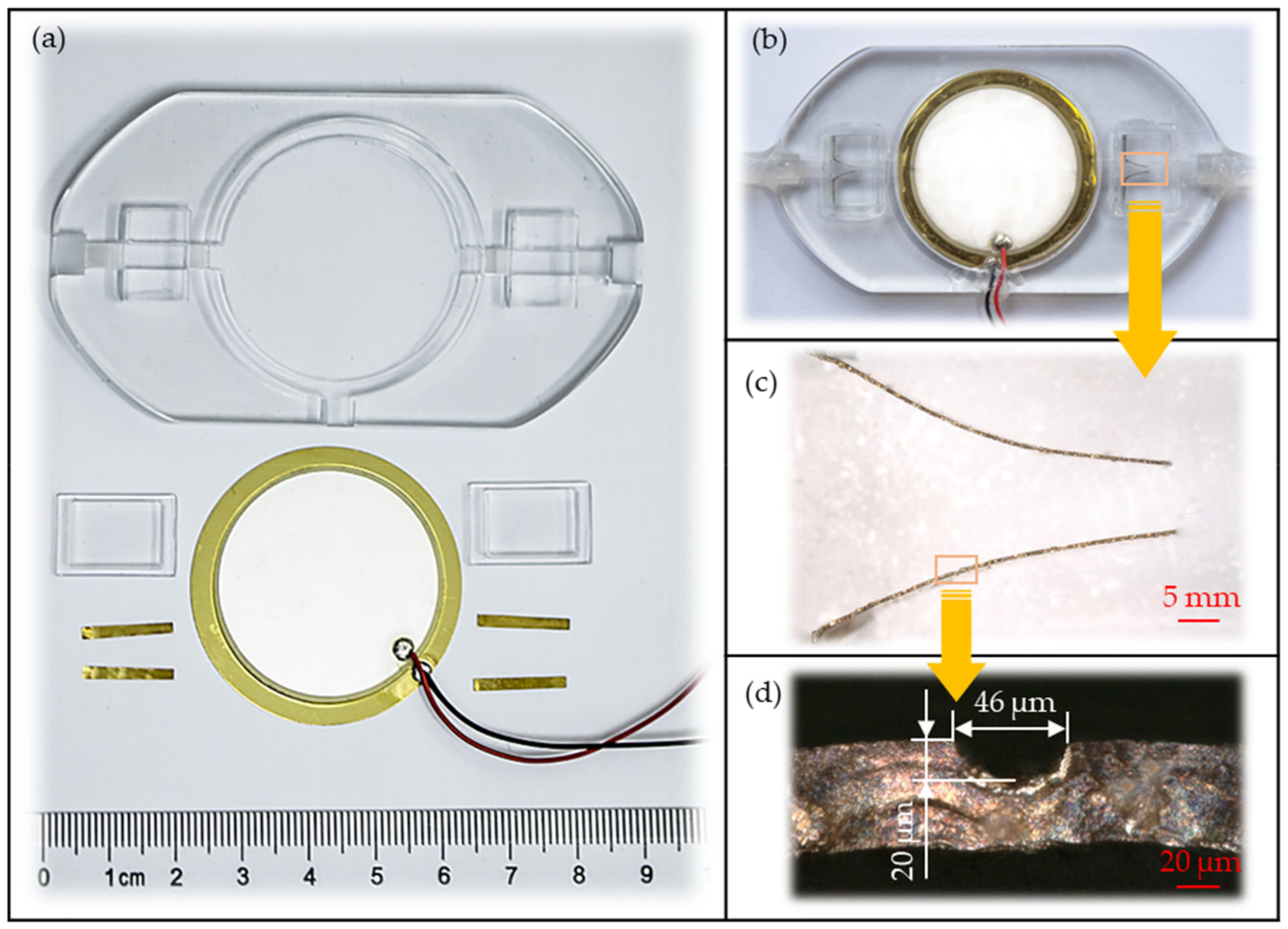
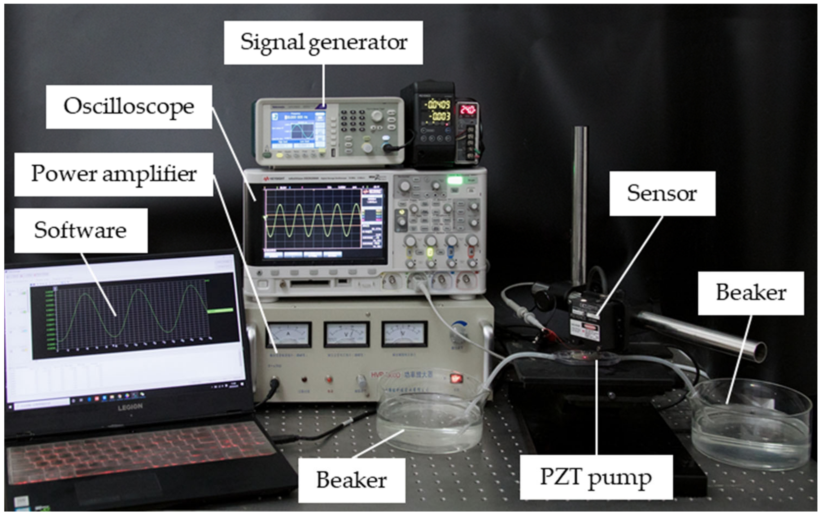
4.1. Fabrication

In order to verify the availability of the pump and the correctness of the theoretical analysis, a prototype of the PPFV has been fabricated. To facilitate the observation of the state of the valve, the pump body and the valve covers were fabricated with transparent photosensitive resin and 3D-printed. The flexible valves were made of brass and their shape was produced by laser-cutting technology. Piezo-element (KS-412T19A, Cosson, Dongguan, China) was used as the PZT vibrator, which was mainly composed of a PZT-8 ceramic wafer and a brass substrate. Photos of the prototype are shown in Figure 4. The dimensions of the prototype are shown in Table 1, and the size parameters of the PZT vibrator are shown in Table 2.
After preparing the parts needed for the manufacturing of the prototype, it was assembled and combined. Firstly, the PZT vibrator was fixed in the center of the pump body with epoxy adhesion. Secondly, the flexible valves were made and installed. The uniform hinges on the leaflets were made with a sharp blade, the fixed ends of the leaflets were glued into the fixing grooves of the pump body with vulcanized silicone rubber, and the initial clearance of the free ends was adjusted with tweezers under the super depth microscope system (VHX-600, Keyence, Osaka, Japan). Finally, the valve covers were glued to the corresponding position of the pump body with vulcanized silicone rubber to seal the flow channel of the pump body.

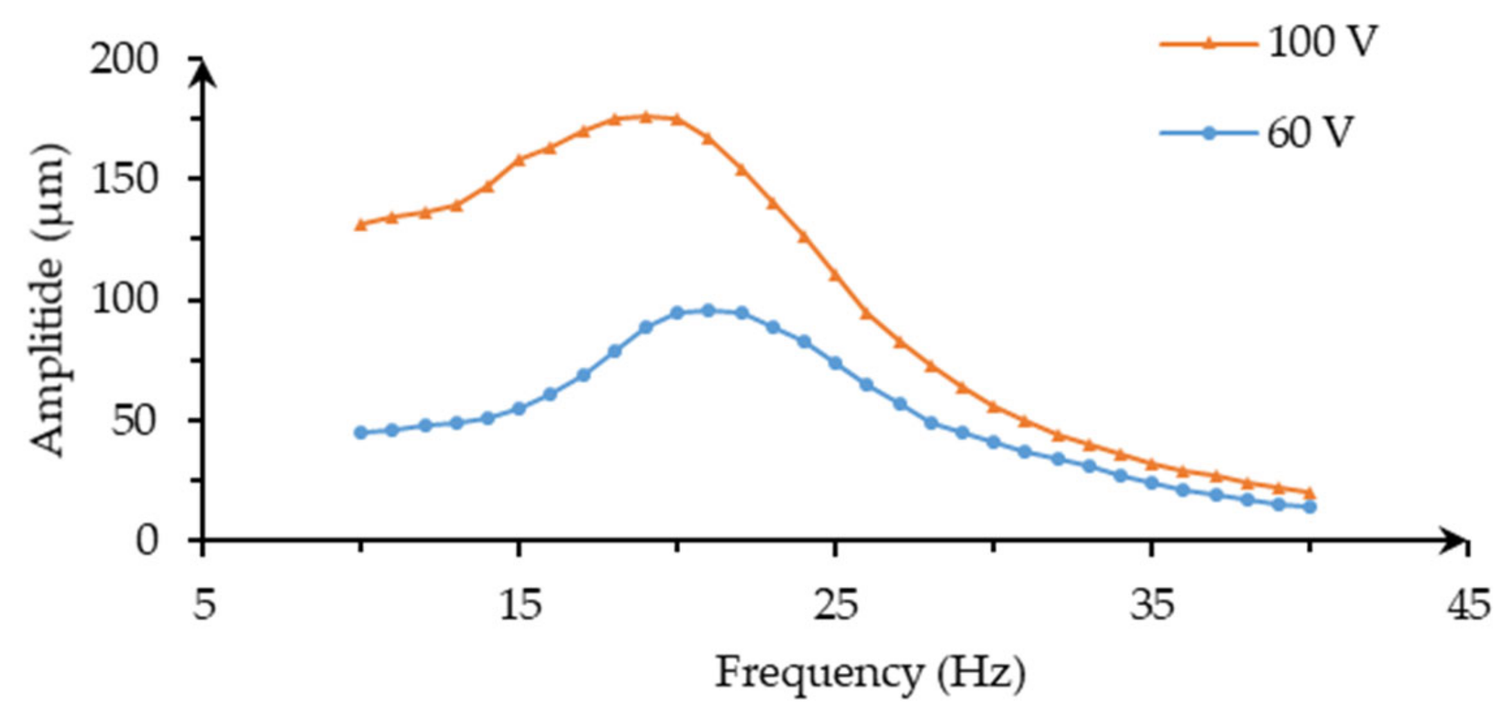
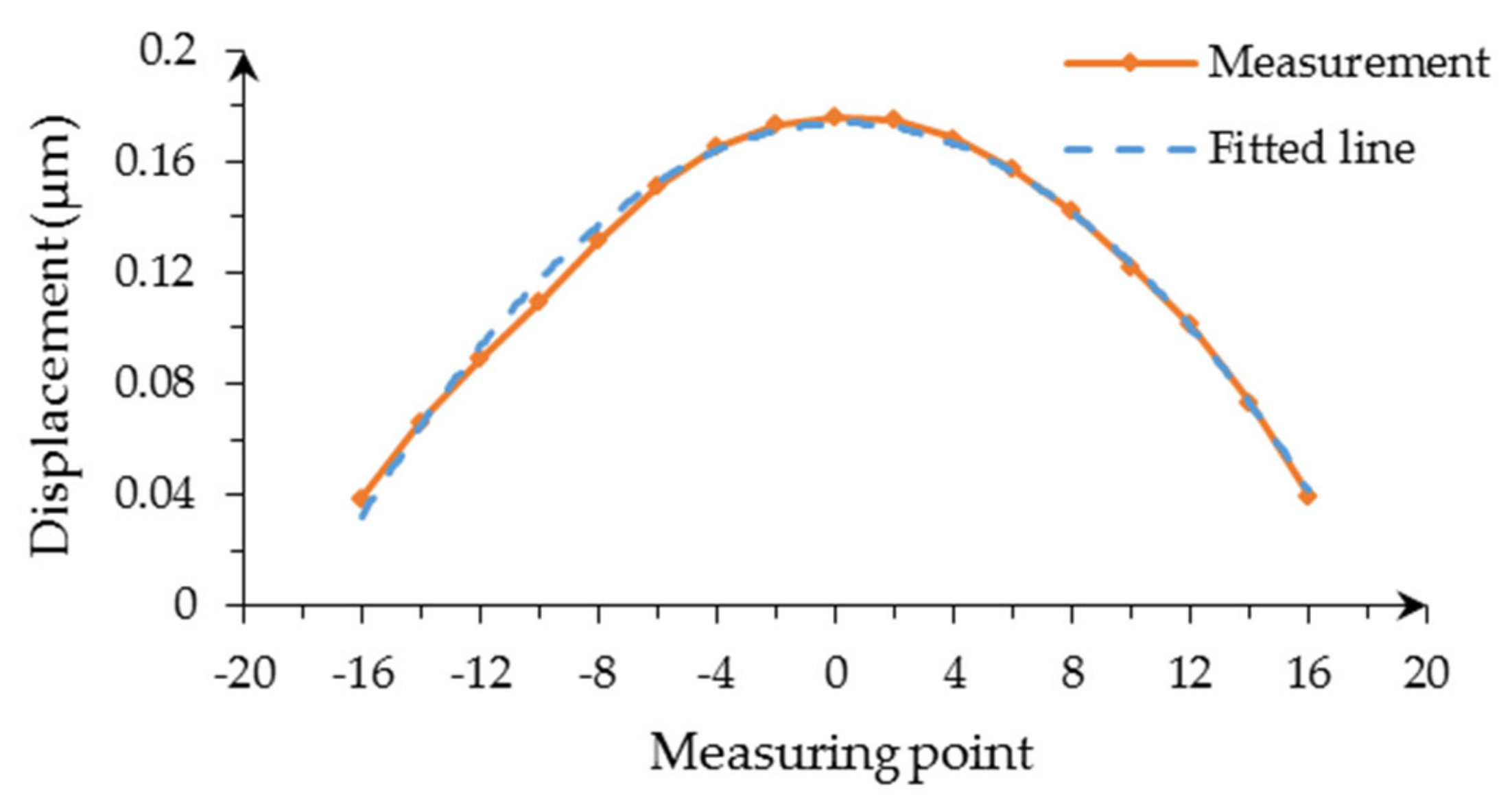
4.2. Amplitude Measurement

The amplitude measurement of the PZT vibrator was carried out to explore the performance of the actuator. The fluid used in the experiment was room temperature deionized water. The photo of the amplitude test is shown in Figure 5. A signal generator (AFG1062, Tektronix, Beaverton, OR, USA) generated sinusoidal voltage signals of different frequencies, which were amplified by a power amplifier (HVP-300D, Nanjing Foneng, Nanjing, China) and applied to the PZT vibrator. In addition, an oscilloscope (DSO-X2004A, Keysight, Santa Rose, CA, USA) monitored the output signal. When the PZT vibrator was excited, the corresponding action occurred.
A laser displacement sensor (LK-H020, KEYENCE, Japan) with an accuracy of 0.1 μm was used to collect the vibration displacement of the PZT vibrator center, and the collected data was transmitted to the corresponding software of the computer, and the amplitude could be obtained by data analysis. Last but not least, in order to reduce errors, the results of this and subsequent experiments are the average values obtained after two identical measurements.
The relation between the amplitude and frequency of the PZT vibrator at 60 V and 100 V is shown in Figure 6. Within the frequency range of 10–40 Hz, the relationship between amplitude and frequency is non-linear. When the frequency of the applied alternating voltage is close to or equal to the natural frequency of the PZT vibrator, the PZT vibrator produces a large vibration, that is, resonance [21]. Therefore, the amplitude of the PZT vibrator increases first and then decreases with the increase in frequency, which is primarily determined by the PZT vibrator’s own properties. When the voltage was 60 V, the largest amplitude was 96 μm and the resonant frequency of the PZT vibrator was about 21 Hz. At 100 V, the largest amplitude was 176 μm and the resonant frequency was about 19 Hz. The difference in resonance frequency between them is mainly due to the different voltage applied. When other conditions are the same, the amplitude of the PZT vibrator will be different with different voltage because it will affect the quantity of the fluid in the pump chamber. The natural frequency formula of the vibration system is as follows:
f 0 = k m
where k is the total stiffness of the system, and m is the total mass of the system. Since the applied voltage and frequency do not affect the total stiffness of the system, only the total mass of the system will be changed. In addition, the vibration velocity of the PZT vibrator will lead to the change of the flow rate, and the change of the flow rate will affect the inertia of the whole system. This is also interpreted as “additional mass”. The increase of additional mass will reduce the natural frequency of vibration [22]. Therefore, in different voltage conditions, the natural frequency of the PZT vibrator will be different.
At a voltage of 100 V and a frequency of 19 Hz, the maximum displacements of 17 points in the diameter direction of the PZT vibrator were measured. The experimental results are shown in Figure 7. The maximum displacement of each point was fitted by curve, and the parabolic function was obtained as follows:
ω r =   0.0005 r 2   +   0.0003 r   +   0.1747
According to Equation (1), the volume change quantity in a quarter period can be calculated as follows:
Δ V = 2 π 0 18.5 ω r r d r
The calculated Δ V is 0.135 mL.

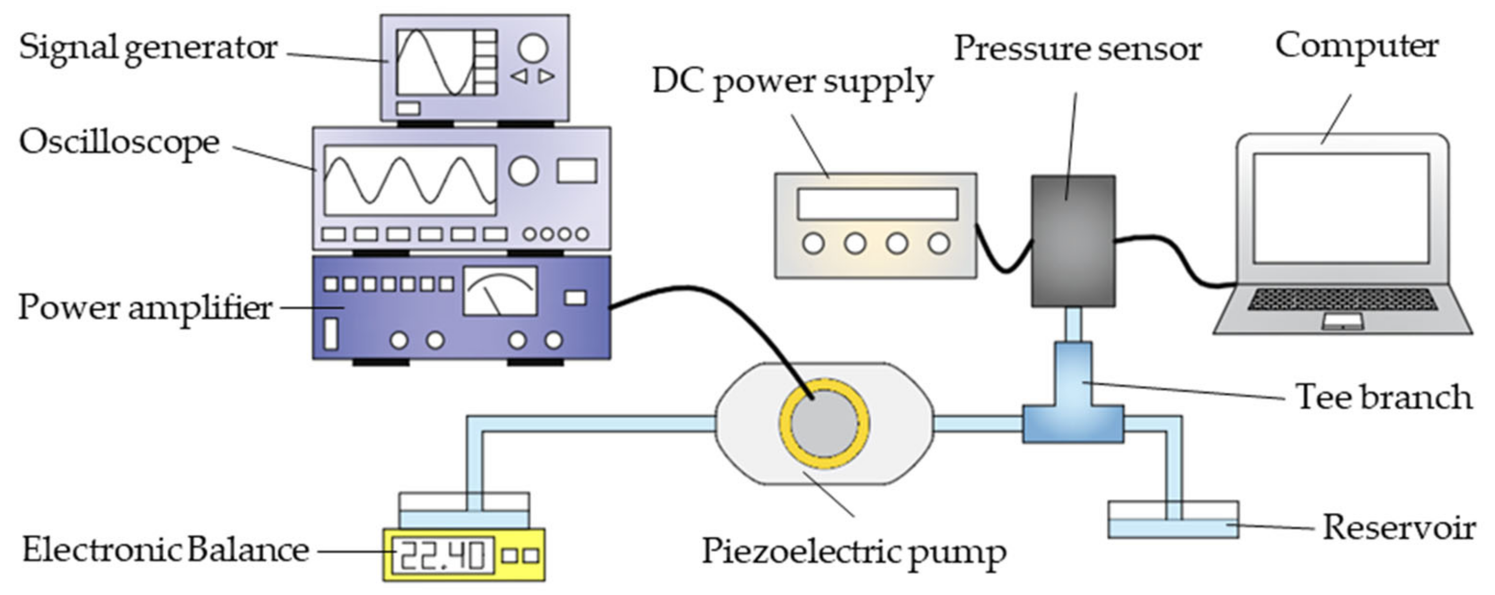
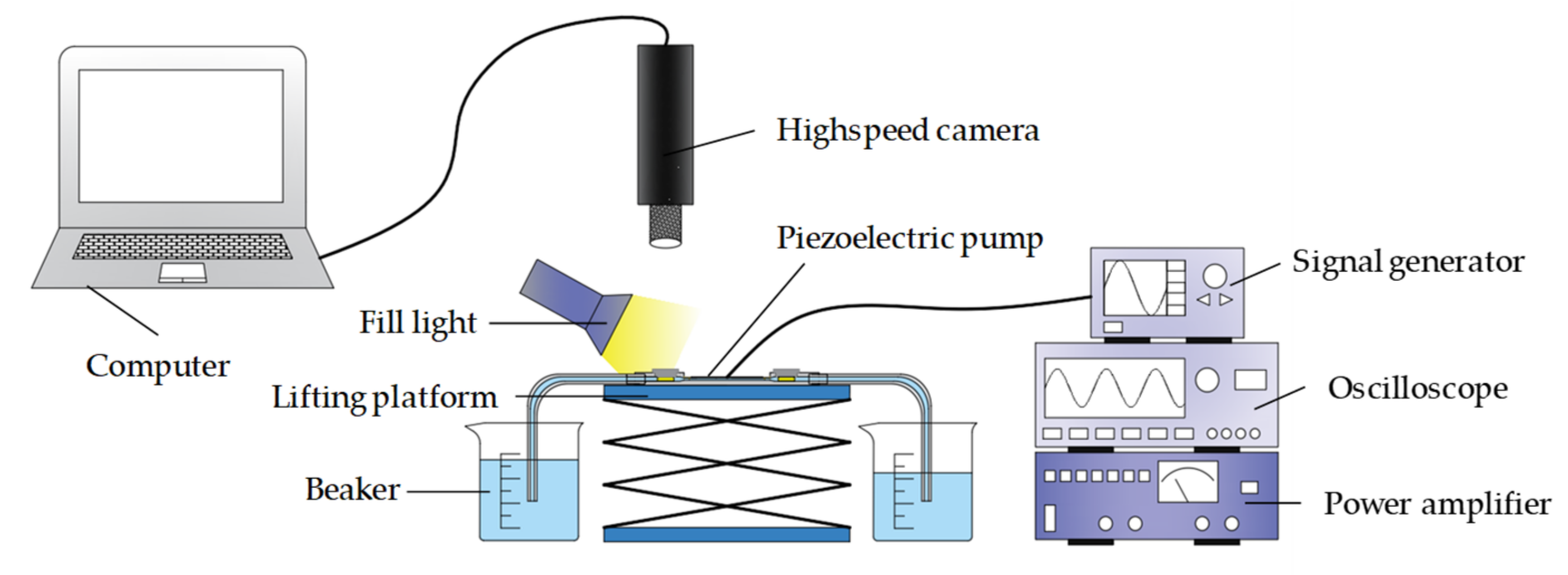
4.3. Flow Rate and Output Pressure Measurement

The output performance experiments of the PPFV were implemented. The experimental schematic is illustrated in Figure 8. The accuracy of the electronic balance is 0.01 g, and the accuracy of the pressure sensor is 0.01 Pa. To reduce siphon effects, we selected large diameter tanks and tried to keep the liquid level in both tanks at the same height, and at the same time, reduce the test time to improve the accuracy of the experiments.
The flow rate–frequency relationships of the prototype at different voltages are shown in Figure 9. It shows that when the voltages were 60 V, 80 V, and 100 V, the maximum flow rates were 55.78 mL/min, 89.02 mL/min, and 119.61 mL/min, respectively. The frequency points corresponding to these maximum flow rates were all located at 25 Hz. Under different voltages, the curves showed similar rules. Within the range of 10–25 Hz, the frequency was positively correlated with the flow rate, and with the increase in frequency, the flow rate also increased. What is more, within the range of 25–40 Hz, the flow rate decreased with the increase in frequency. In the range of 10–40 Hz, the main reason why the flow rate first rises and then falls is that the amplitude of the PZT vibrator varies with the frequency. In the selected input signals, the flow rate reached its maximum while the frequency was 25 Hz and the voltage was 100 V. When the voltage was lower than 80 V and the frequency was lower than 15 Hz, the flow rates were almost less than 5 mL/min. The curves of the flow rate with the voltage are shown in Figure 9. Obviously, in the voltage range of 40 V to 100 V, the voltage is almost positively correlated with the flow rate; the flow rate increases when the voltage increases. What is more, the overall trend of flow rate variation is basically consistent with the trend of amplitude variation.
Figure 10 presents the results of the output pressure test at a voltage of 100 V. The curve of the output pressure is approximately a quadratic curve. When comparing it with Figure 9, it can be noted that the trend of the flow rate curve is basically the same. When the frequency was 25 Hz, the output pressure reached the maximum, 6.16 kPa. The results show that the PPFV has a higher flow rate and higher output pressure when the frequency is about 25 Hz.
The performance of this pump was compared with that of the same type of pump. In these two pumps, only the structure of the valves was different. Pump A was equipped with the flexible valves in this study, and Pump B was installed with the compliant structure proposed in the literature [19]. Both pumps were tested at a voltage of 100 V, changing only the driving frequency of the PZT vibrator. The comparison results are presented in Figure 11 and Figure 12. From the results, they work at the same optimal frequency point, 25 Hz. The maximum flow rate of Pump A is 119.61 mL/min, and the maximum output pressure is 6.16 kPa. Pump B has a maximum flow rate of 96.04 mL/min and a maximum output pressure of 5.61 kPa. As a result, the flow rate of Pump A is 24.5% higher than that of Pump B, and the output pressure is 13% higher because the flexible valves of Pump A have a hinged structure, which enhances the flexibility of the valves and makes the valves open and close more flexibly. Therefore, Pump A performs better than Pump B under the same driving conditions.

4.4. Working-State Analysis

The performance of the prototype was tested at different driven voltages, 100, 80, and 40 V at 25 Hz. The working-state of the prototype was filmed with a high-speed camera (5KF20, FuGuang AgileDevice, Hefei, China), as shown in Figure 13. The deformations of one flexible valve in a cycle are shown in Figure 14. It can be seen that the shape of the flexible valve changes with the variation of pressure during the suction and exhaustion strokes of the prototype.
When the voltage was 100 V, the deformation of the leaflets was strong, there was no clearance between them sometimes in a cycle, and the flow channel was completely blocked. It was a pump with completely closed valves. When the voltage was 80 V, although the flexible valve was deformed, there was always a clearance between the two leaflets. It was a pump with normally open valves. While when the voltage was 40 V, the maximum displacement of the flexible valve was 0.04 mm, which can be ignored because it was only about 5% of the initial clearance of the valve. The flexible valves maintain the original clearance and its structure shape is similar to the valveless PZT pump with cone-shaped tubes [23]. Thus, it was a valveless pump in this condition.
If the PZT pump can be classified into a valveless PZT pump and a valved PZT pump according to if there is a moment in a period when the flow channel is completely blocked, then the pump with the moment is the valved PZT pump and the pump without the moment is the valveless PZT pump [24]. Therefore, the PPFV can be treated as a valved PZT pump when the voltage is 100 V, while it is a valveless PZT pump when the voltages are 80 and 40 V. This proves that the PPFV can achieve a transition between the valveless state and the valved state by adjusting the voltage, and can realize the free conversion of a large flow rate, high pressure difference and a small flow rate, low pressure difference.

5. Conclusions

In this paper, in order to integrate the valved PZT pump and the valveless PZT pump, a flexible valve was proposed and applied to a PZT pump. The main conclusions are drawn as follows:
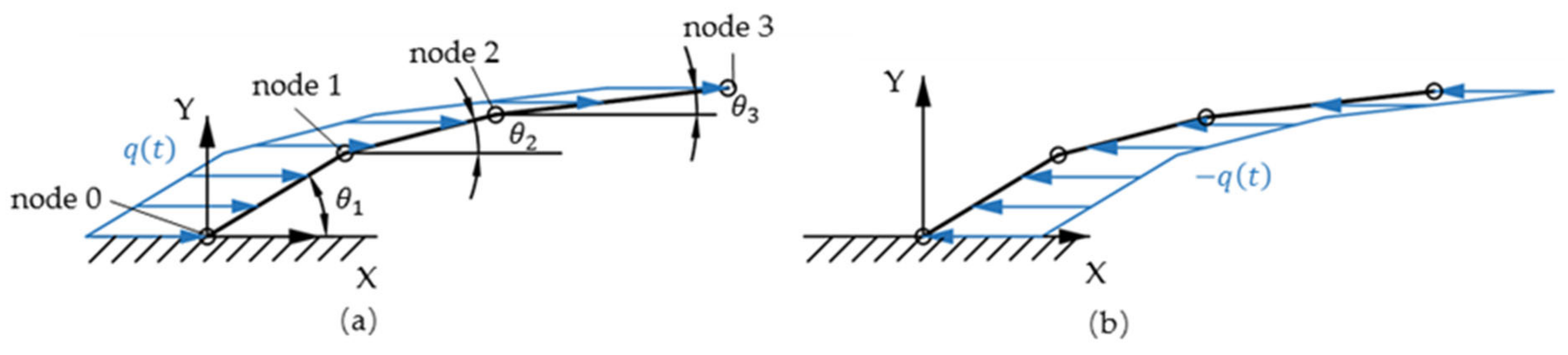
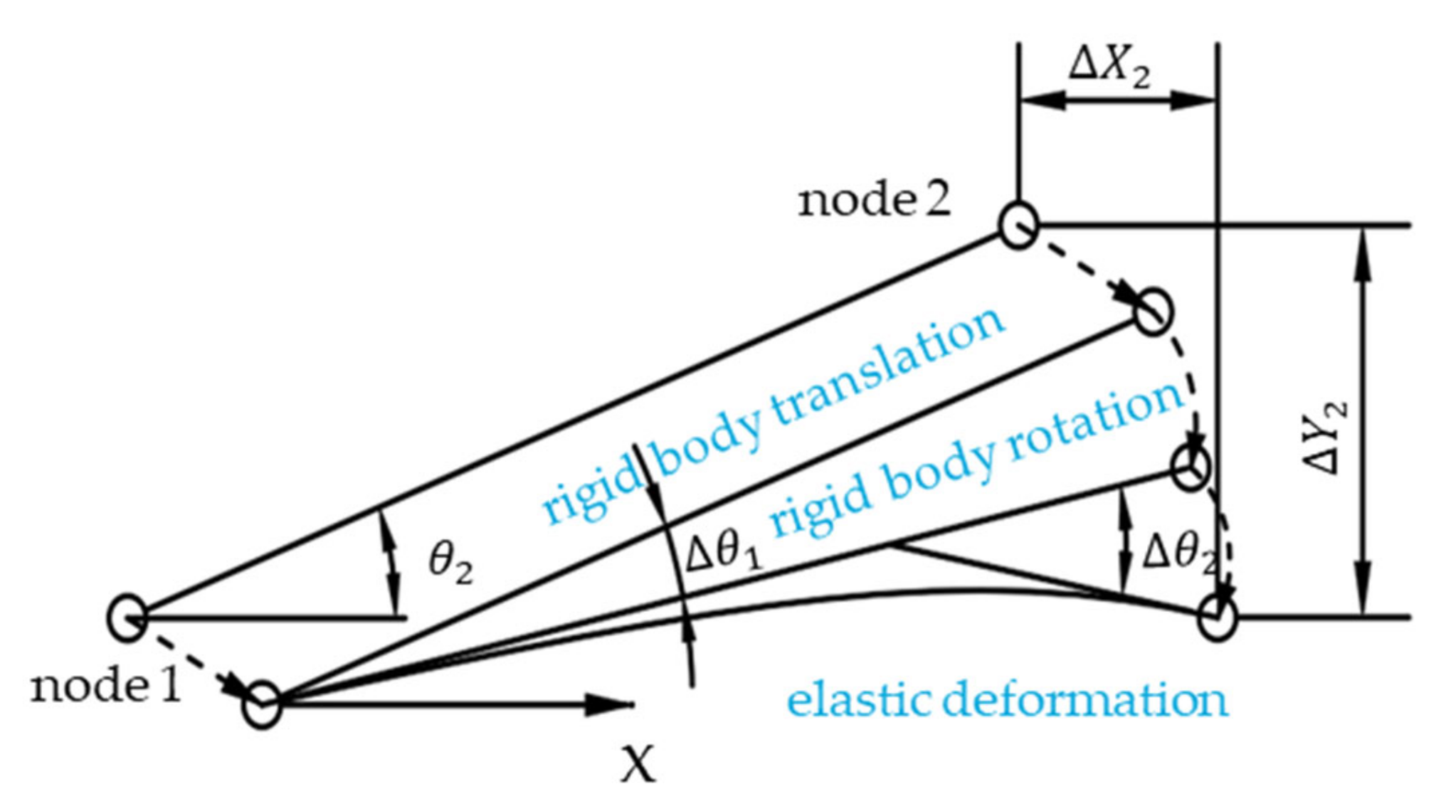
  • The working principle of the PPFV was introduced, a simplified model of the flexible valve was established, and its response to the loads was analyzed. It is known that the pressure change in the pump chamber caused by the vibration of the PZT vibrator is beneficial to the realization of the valve transport function. It was proved theoretically that this kind of pump can realize the conversion between a valved state and a valveless state by controlling the input signal of the PZT vibrator.
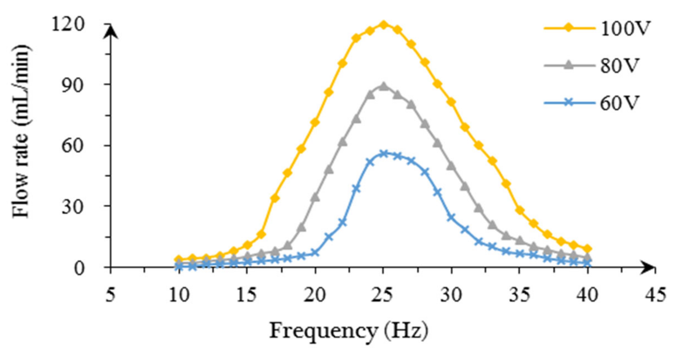
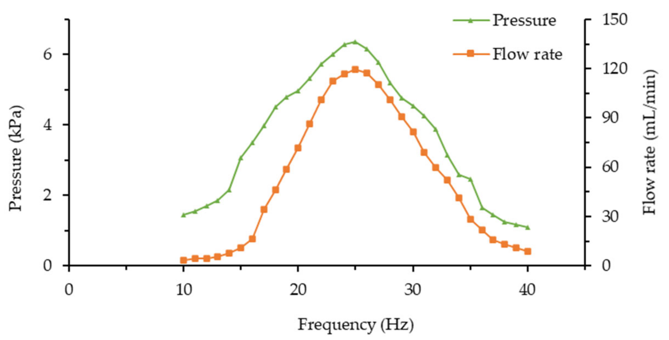
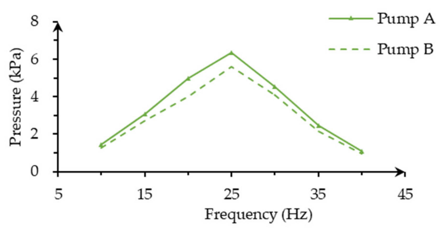
  • The prototype of the PZT pump with flexible valves was manufactured, and its output performance was obtained through experimental research. The flow rate of the pump increased with the increase in voltage, but the flow rate–frequency relationships were not linear. The frequency corresponding to the maximum flow rate was not sensitive to the voltage change. The maximum flow rate measured under the voltage of 100 V was 119.61 mL/min (25 Hz), and the maximum output pressure was 6.16 kPa (25 Hz).
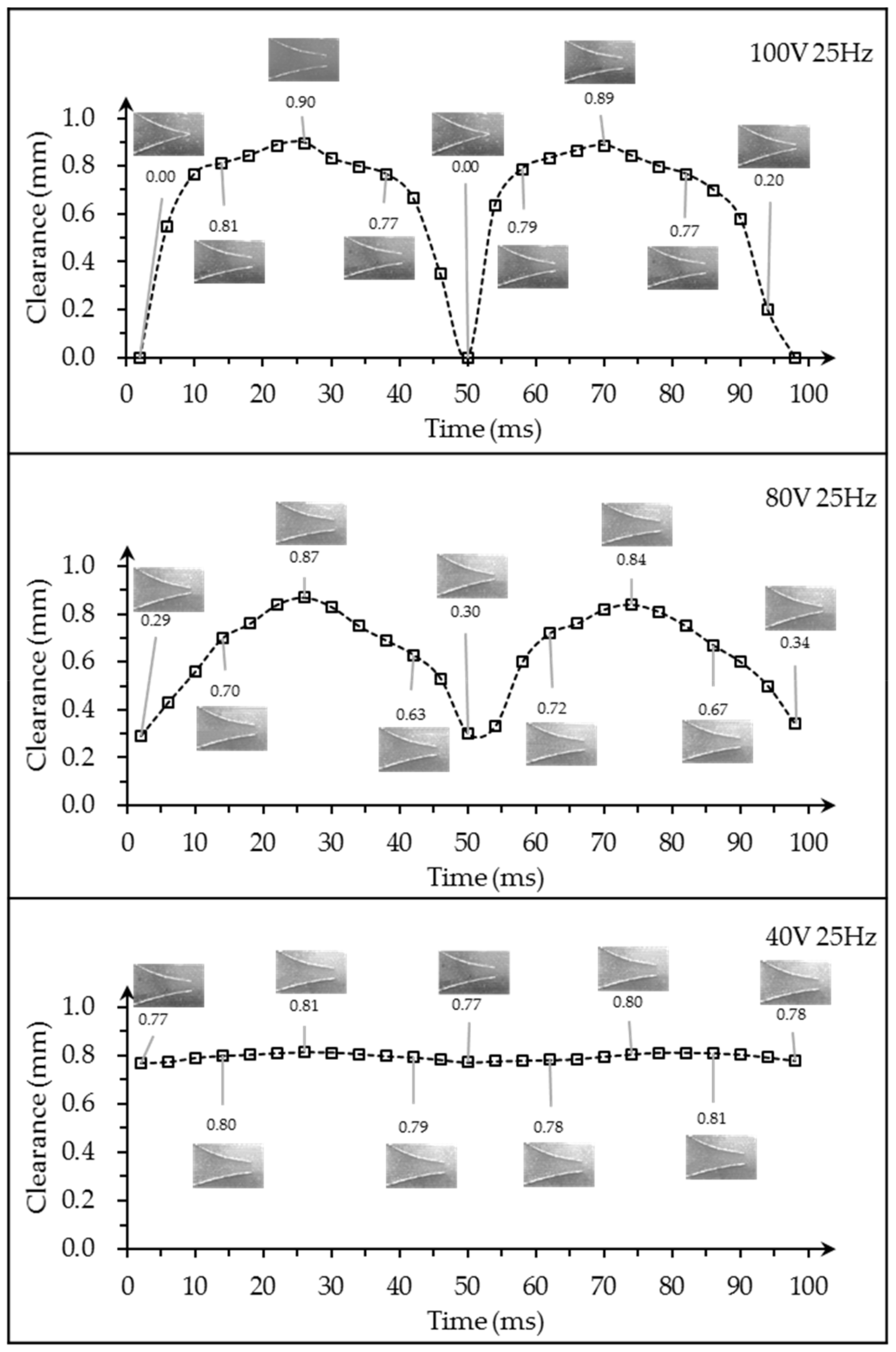
  • We observed the working-state of one flexible valve in different input voltages, 100, 80, and 40 V at 25 Hz. It showed that the valved pump and the valveless pump existed in one, which proved that the valved state and the valveless state of the pump can be switched by adjusting the voltage. When the voltage was 100 V, it was a valveless PZT pump with a large flow rate and high output pressure. However, it was a valveless PZT pump with a small flow rate and low pressure difference when the voltage was lower than 80 V.

Author Contributions

This paper represents a result of collaborative teamwork. W.H. and J.Z. conceived and designed the experiments; L.L. performed the experiments and wrote the manuscript; Z.C. and X.C. analyzed the data; Z.H. provided constructive suggestions; J.D. and F.Z. revised the manuscript. All authors have read and agreed to the published version of the manuscript.

Funding

This research was funded by “Graduate AbilityPromotion Plan of Guangzhou University, Guangzhou, China, grant number 2019GDJC-M20”, “Guangdong Basic and Applied Basic Research Foundation, Guangdong, China, grant number 2019B1515120017” and “National Natural Science Foundation of China (NSFC), China, grant number 51705093”.

Institutional Review Board Statement

Not applicable.

Informed Consent Statement

Not applicable.

Conflicts of Interest

The authors declare no conflict of interest.

Appendix A

The connection point between the fixed end and the free end is Node 0, which is the origin of the coordinate system, as shown in Figure A1.
Figure A1. The simplified model of the valve. (a) The forward force model; (b) the reverse force model.
Applsci 11 02909 g0a1
Assuming that the inlet valve in the suction stroke and the outlet valve in the exhaustion stroke were subjected to a uniformly distributed load q t , then the loads received at Node 1 were
f x 1 = 1 3 q t sin θ 2 + sin θ 3 L
m 1 = 1 18 q t sin θ 2 + sin θ 3 2 L 2
where f x i is the component force along the x-axis at Node i , m i is the bending moment at Node   i , θ i is the initial bending angle of Unit i , and   i = 1, 2, 3.
The deformation of Unit 1 is shown in Figure A2. m 1 , f x 1 and q t act together in Unit 1, and the displacement caused by m 1 is calculated first, as follows:
ω 1 = m 1 L 2 18 E I
Δ θ 1 = m 1 L 3 E I
where E is the elastic modulus of the material, I is the moment of inertia of the section, and ω i and Δ θ i are, respectively, the deflection and the angular deformation of Node i under the action of m i , i = 1, 2, 3.
Figure A2. Deformation analysis of Unit 1.
Applsci 11 02909 g0a2
The deformation of f x 1 is calculated as follows:
ω 1 = f x 1 sin θ 1 L 3 81 E I
Δ θ 1 = f x 1 sin θ 1 L 2 18 E I
where ω i and Δ θ i are, respectively, the deflection and the angular deformation of Node i under the action of f x i , i = 1, 2, 3.
The deformation of q t is calculated as follows:
ω 1 = q t sin θ 1 L 4 648 E I
Δ θ 1 = q t sin θ 1 L 3 162 E I
where ω i and Δ θ i are, respectively, the deflection and the angular deformation of Node i under the action of q t , i = 1, 2, 3.
The displacement of Unit 1 is calculated as follows:
ω 1 = ω 1 + ω 1 + ω 1
Δ θ 1 = Δ θ 1 + Δ θ 1 + Δ θ 1
where ω i and Δ θ i are the deflection and angular deformation of Node i , respectively, and i equals 1, 2, and 3.
The elastic deformation of Unit 1 is the total displacement of Node 1, which is converted to the OXY coordinate system and obtained that
Δ Y 1 = ω 1 cos θ 1
After the deformation of Node 1 is obtained, the deformation of the end of Unit 2 can be further calculated. To ensure the continuity between the units, Unit 2 should make a rigid body translation and a rigid body rotation firstly, and then it should be considered as a cantilever inserted into Node 1. Thus, the displacement at Node 2 includes the former displacement, the elastic displacement, and the rigid displacement. The deformation of Unit 2 is shown in Figure A3.
Figure A3. Deformation analysis of Unit 2.
Applsci 11 02909 g0a3
The loads at Node 2 are calculated as follows:
f x 2 = 1 3 q t sin θ 3 Δ θ 1 L
m 2 = 1 18 q t sin 2 θ 3 Δ θ 1 L 2
The displacement caused by m 2 is calculated as follows:
ω 2 = m 2 L 2 18 E I
Δ θ 2 = m 2 L 3 E I
The deformation of f x 2 is calculated as follows:
ω 2 = f x 2 sin θ 2 Δ θ 1 L 3 81 E I
Δ θ 2 = f x 2 sin θ 2 Δ θ 1 L 2 18 E I
The deformation of q t is calculated as follows:
ω 2 = q t sin θ 2 Δ θ 1 L 4 648 E I
Δ θ 2 = q t sin θ 2 Δ θ 1 L 3 162 E I
The displacement of Node 2 is calculated as follows:
ω 2 = ω 2 + ω 2 + ω 2
Δ θ 2 = Δ θ 2 + Δ θ 2 + Δ θ 2
The conversion to the coordinate system OXY is calculated as follows:
Δ y 2 e = ω 2 cos θ 2 Δ θ 1
where Δ y i e is the elastic displacement of Node i along the y-axis, and i equals 2 and 3. In addition to the elastic displacement, there is also the displacement caused by the rigid body rotation of Unit 1, calculated as follows:
Δ y 2 γ = 1 3 L sin θ 2 Δ θ 1 sin θ 2
where Δ y i γ is the rigid displacement of Node i along the y-axis, i = 2, 3.
Adding the displacement of Unit 1, and the total displacement of Unit 2 is calculated as follows:
Δ Y 2 = Δ Y 1 + Δ y 2 e + Δ y 2 γ
Similarly, the deformation of Node 3 is calculated. Unlike Node 2, Node 3 is only affected by q t . The elastic deformation at Node 3 is calculated as follows:
ω 3 = q t sin θ 3 Δ θ 2 Δ θ 1 L 4 648 E I
Δ θ 3 = q t sin θ 3 Δ θ 2 Δ θ 1 L 3 162 E I
The elastic displacement and the rigid displacement at Node 3 is calculated as follows:
Δ y 3 e = ω 3 cos θ 3 Δ θ 2 Δ θ 1
Δ y 3 γ = 1 3 L sin θ 3 Δ θ 2 Δ θ 1 cos θ 3
Adding the total displacement of Unit 2, we get the total displacement of Unit 3, as follows:
Δ Y 3 = Δ Y 2 + Δ y 3 e + Δ y 3 γ
As the initial clearance between the two leaflets is Y0, the leaflets are deformed due to the force when the PZT vibrator is working, so the clearance Y’ between the deformed leaflets is calculated as follows:
Y = Y 0 + 2 Δ Y 3
For the outlet valve in the suction stroke and the inlet valve in the exhaustion stroke, they are subjected to q t at some point, as shown in Figure A1b. The deformation analysis is the same as above.

References

  1. Gidde, R.R.; Pawar, P.M.; Dhamgaye, V.P. Fully coupled modeling and design of a piezoelectric actuation based valveless micropump for drug delivery application. Microsyst. Technol. Micro Nanosyst. Inf. Storage Process. Syst. 2020, 26, 633–645. [Google Scholar] [CrossRef]
  2. Liu, C.; Zhu, Y.C. Simulation and experimental study of direct spray type piezoelectric air pumps based on synthetic jet. Microsyst. Technol. Micro Nanosyst. Inf. Storage Process. Syst. 2019, 25, 4445–4454. [Google Scholar] [CrossRef]
  3. Saren, A.; Smith, A.R.; Ullakko, K. Integratable magnetic shape memory micropump for high-pressure, precision microfluidic applications. Microfluid. Nanofluidics 2018, 22, 1–10. [Google Scholar] [CrossRef]
  4. Laser, D.J.; Santiago, J.G. A review of micropumps. J. Micromech. Microeng. 2004, 14, R35–R64. [Google Scholar] [CrossRef]
  5. Bian, K.; Huang, Z.; Bao, Q.B.; Zhang, J.H.; Lai, L.Y.; Chen, X.S.; Chen, Z.L. Design and Experiment of Streamlined Piezoelectric Pump with Low Vortex and Large Flow Rate. Trans. Nanjing Univ. Aeronaut. Astronaut. 2020, 37, 155–163. [Google Scholar]
  6. Dong, J.S.; Cao, Y.; Chen, Q.Q.; Wu, Y.; Liu, R.G.; Liu, W.S.; Yang, Y.; Yang, Z.G. Performance of single piezoelectric vibrator micropump with check valve. J. Intell. Mater. Syst. Struct. 2020, 31, 117–126. [Google Scholar] [CrossRef]
  7. Wang, J.T.; Zhao, X.L.; Chen, X.F.; Yang, H.R. A Piezoelectric Resonance Pump Based on a Flexible Support. Micromachines 2019, 10, 169. [Google Scholar] [CrossRef] [PubMed] [Green Version]
  8. Zeng, P.; Lin, J.G.; Cheng, G.M.; Yang, Z.G.; Wu, B.D.; Liu, G.J. A Study on Testing for Micro Piezo-pump with Integral Valve. Piezoelectric Acoustooptics 2006, 28, 594–596. [Google Scholar]
  9. Woo, J.; Sohn, D.K.; Ko, H.S. Performance and flow analysis of small piezo pump. Sens. Actuators A Phys. 2020, 301, 111766. [Google Scholar] [CrossRef]
  10. Wang, Y.; Zhang, J.; Liu, R. Theoretical and Experimental Research on the Piezoelectric Pump with Helical Linear Shaped Valve. J. Mech. Eng. 2016, 52, 144–150. [Google Scholar] [CrossRef]
  11. Zhang, J.H.; Huang, J.; Hu, X.Q.; Xi, Q.X. Novel piezoelectric pump with “E”-shaped valve found from sub-experiments. Front. Mech. Eng. China 2010, 5, 212–218. [Google Scholar] [CrossRef]
  12. He, X.H.; Cai, S.C.; Deng, Z.D.; Yang, S. Experimental and numerical study of flow characteristics of flat-walled diffuser/nozzles for valveless piezoelectric micropumps. Proc. Inst. Mech. Eng. Part C J. Mech. Eng. Sci. 2017, 231, 2313–2326. [Google Scholar] [CrossRef]
  13. Stemme, E.; Stemme, G. A valveless diffuser/nozzle-based fluid pump. Sens. Actuators A Phys. 1993, 39, 159–167. [Google Scholar] [CrossRef]
  14. Forster, F.K.; Bardell, R.L.; Afromowitz, M.A.; Sharma, N.R.; Blanchard, A. Design, fabrication and testing of fixed-valve micro-pumps. Asme Publ. Fed 1995, 234, 39–44. [Google Scholar]
  15. Zhang, J.H.; Leng, X.F.; Zhao, C.S. A spiral-tube-type valveless piezoelectric pump with gyroscopic effect. Chin. Sci. Bull. 2014, 59, 1885–1889. [Google Scholar] [CrossRef]
  16. Huang, J.; Zou, L.; Tian, P.; Wang, Y.; Zhang, Q. Development of a valveless piezoelectric pump with vortex diodes. J. Micromech. Microeng. 2019, 29, 125006. [Google Scholar] [CrossRef]
  17. Tang, M.; Bao, Q.B.; Zhang, J.H.; Ning, Q.S.; Chen, C.B.; Huang, J.; Wu, C.Y. Design and Experimental Verification of a PZT Pump with Streamlined Flow Tubes. Appl. Sci. 2019, 9, 3881. [Google Scholar] [CrossRef] [Green Version]
  18. Li, F.; Zhang, J.H.; Tang, M.; Chen, C.B.; Bao, Q.B. Experimental study of valveless piezoelectric pump with raindrop-shaped tubes. In Proceedings of the 2018 International Conference on Service Robotics Technologies, Chengdu, China, 16–19 March 2018. [Google Scholar]
  19. Bao, Q.B.; Zhang, J.H.; Tang, M.; Huang, Z.; Lai, L.L.; Wu, C.Y. A novel PZT pump with built-in compliant structures. Sensors 2019, 19, 1301. [Google Scholar] [CrossRef] [Green Version]
  20. Li, L.L. Chain Algorithm for Solving Large Deflection and Its Application in Compliant Mechanisms’ Analysis. Ph.D. Thesis, Xidian University, Xi’an, China, 2012. [Google Scholar]
  21. Li, Y.L.; Zhang, J.H.; Xia, Q.X.; Lu, J.Z. Research on the Dynamic Characteristics of the Actuator for the Piezoelectric Pump. China Mech. Eng. 2007, 17, 2088–2093. [Google Scholar]
  22. Zeng, D.; Chen, Y. High-Order Modal Shape Measurement of Centrifugal Impeller Blade by Using Marco Fiber Composite. J. Propuls. Technol. 2020, 41, 1612–1620. [Google Scholar]
  23. Zhang, J.H.; Wang, Y.; Huang, J. Advances in valveless piezoelectric pump with cone-shaped tubes. Chin. J. Mech. Eng. 2017, 30, 766–781. [Google Scholar] [CrossRef]
  24. Zhang, J.H.; Fu, J.; Zhang, F.; Zhou, Y.; Huang, J.; Huang, W.Q.; Bian, K.; Liu, P.C. Redefining valves in volume pump. In Proceedings of the ACTUATOR 2018: 16th International Conference on New Actuators, Bremen, Germany, 25–27 June 2018. [Google Scholar]
Figure 1. Structure of the flexible valve.
Applsci 11 02909 g001
Figure 2. Structure diagram of the piezoelectric pump with flexible valves (PPFV).
Applsci 11 02909 g002
Figure 3. The simplified model and deformation of the valve.
Applsci 11 02909 g003
Figure 4. The PPFV: (a) Parts and components of the pump; (b) the assembled prototype; (c) enlarged view of the valve; (d) a hinge of the valve.
Applsci 11 02909 g004
Figure 5. Amplitude detection platform.
Applsci 11 02909 g005
Figure 6. Curves of frequency and amplitude.
Applsci 11 02909 g006
Figure 7. The maximum displacement of each point and the fitted curve.
Applsci 11 02909 g007
Figure 8. Traffic and output pressure test platform.
Applsci 11 02909 g008
Figure 9. Curves of flow rate with frequency.
Applsci 11 02909 g009
Figure 10. The output pressure and flow rate curves of the piezoelectric pump, when the voltage was 100 V.
Applsci 11 02909 g010
Figure 11. Flow rate comparison of the same type of pump.
Applsci 11 02909 g011
Figure 12. Output pressure comparison of the same type of pump.
Applsci 11 02909 g012
Figure 13. Observation test platform.
Applsci 11 02909 g013
Figure 14. The observed clearance between the two leaflets in one period.
Applsci 11 02909 g014
Table 1. The size of the PPFV.
ItemSize (mm)
Y00.8
L5
h1.9
b0.05
Flow channel width3.8
Pump chamber diameter37
Pump chamber height1
Table 2. The size parameters of the piezoelectric (PZT) vibrator.
ItemSize (mm)
Brass substrate diameter41
Brass substrate thickness0.23
PZT ceramic diameter35
PZT ceramic thickness0.30
Publisher’s Note: MDPI stays neutral with regard to jurisdictional claims in published maps and institutional affiliations.

