Article

Identification of the Effect of Ultrasonic Friction Reduction in Metal-Elastomer Contacts Using a Two-Control-Loop Tribometer

Institute of Dynamic and Vibration Research, Gottfried Wilhelm Leibniz Universität Hannover, An der Universität 1, 30823 Garbsen, Germany
*
Author to whom correspondence should be addressed.
Appl. Sci. 2021, 11(14), 6289; https://doi.org/10.3390/app11146289
Submission received: 24 May 2021 / Revised: 21 June 2021 / Accepted: 1 July 2021 / Published: 7 July 2021

Abstract

:
Pneumatic cylinders are widely used in highly dynamic processes, such as handling and conveying tasks. They must work both reliably and accurately. The positioning accuracy suffers from the stick-slip effect due to strong adhesive forces during the seal contact and the associated high breakaway forces. To achieve smooth motion of the piston rod and increased position accuracy despite highly variable position dynamics, sliding friction and breakaway force must be reduced. This contribution presents a specially designed linear tribometer that has two types of control. Velocity control allows the investigation of sliding friction mechanisms. Friction force control allows investigation of the breakaway force. Due to its bearing type, the nearly disturbance-free detection of stick-slip transients and the dynamic contact behavior of the sliding friction force was possible. The reduction of the friction force was achieved by a superposition of the piston rod’s movement by longitudinal ultrasonic vibrations. This led to significant reductions in friction forces at the rubber/metal interface. In addition, the effects of ultrasonic frequency and vibration amplitude on the friction reduction were investigated. With regard to the breakaway force, significant success was achieved by the excitation. The force control made it possible to identify the characteristic movement of the sealing ring during a breakaway process.

1. Introduction

The versatile use of pneumatic cylinders in various industrial positioning tasks requires increased efficiency and process quality, hence the demand for the realization of preset velocity profiles. The main problem results from the transient behavior of the cylinder piston rod when starting from standstill and direction reversing. The friction induced stick-slip effects occurring in the sealing contacts significantly restrict the positioning accuracy. Currently used concepts to reduce friction in pneumatic sealing contacts consist either of adapting sealing parameters, such as the materials and geometry, or of parametrizing the contact partners by lubricating or coating the contact surfaces. However, the reduction of contact-friction by applying piezoelectrically excited ultrasonic vibrations is used in many processes of ultrasonic machining, and recently made inroads into pneumatic servo systems [1,2,3,4,5].
Theoretical and experimental investigations on metal–metal coupled contacts go back to the year 1966 and focus on wire drawing processes [6]. In [7], an explanation of macroscopic friction reduction in the presence of ultrasonic vibrations was given using Coulomb’s law for perpendicular and parallel superpositioning of macroscopic movement in sufficient agreement with experimental results. Recently, dynamic friction models were used, e.g., in [8], to explain the stick-slip transients in dry friction contacts assuming elastic–plastic and viscoelastic material properties. The impact of excitation frequency was not taken into account though. The results in [9] state that the sliding friction of metals under longitudinal ultrasonic vibrations is significantly greater than the sliding friction of transverse vibrations, which is 80% weaker. Longitudinal superposition of the piston rod is thus a promising strategy for friction reduction. In [10] a pneumatic actuator with integrated piezo-stack actuators in a cylinder was presented; it reached a 52% friction reduction under dry conditions. Bending and longitudinal vibration modes were investigated therein. In [11] a prototype of a piezoelectrically actuated piston-rod was introduced for the first time; it reduced friction in the static rod and the moving piston seal simultaneously by parallel superimposition of the macroscopic velocity. A pin-on-disc tribometer was introduced in [12] for the experimental investigation of perpendicular induced ultrasonic vibrations. They validated the results with an elastic–plastic "cube" model describing the stiffness variation of the contact asperities.
Any friction-affected process can be subdivided into the occurrence of breakaway transients and dynamic friction behavior. While breakaway transients occur as a transition from sticking or pre-sliding to the sliding state due to the release of pre-stress between the contact opponents, dynamic friction behavior occurs while relative motion or sliding takes place at the macro-scale. When friction reduction in elastomer–metal coupled contacts is induced by ultrasonic vibrations, these two friction states are accompanied, besides material wear, with multi-frequency excited friction characteristics, such as variations of contact stiffness, variations of shear stress distribution [13] and local occurrences of glass transitions [14,15]. Thus, the experimental investigation of ultrasonic friction reduction requires individual identifications of these effects. For this purpose, two types of control are used in the linear tribometer introduced in this contribution. The velocity control allows the investigation of dynamic friction mechanisms and the friction force control enables the investigation of breakaway transients. All transitions of the frictional contact from static to sliding friction, including hysteretic pre-sliding, can be examined and quantitatively investigated with respect to the global parameters relative to velocity of the contact partners, the ultrasonic amplitude and the sealing material. Through the use of an air bearing in combination with a voice coil motor, decoupled identification of the friction from the peripheral test bench structure was realized and has novelty value compared to the current state of friction research. The superimposition by ultrasonic vibrations was performed in the longitudinal direction, in parallel to the piston velocity.
The topology of the tribometer is introduced in the following section. The identification procedures were validated by the initial trends obtained from experiments regarding the influence of the ultrasound amplitude.

2. Experimental Setup

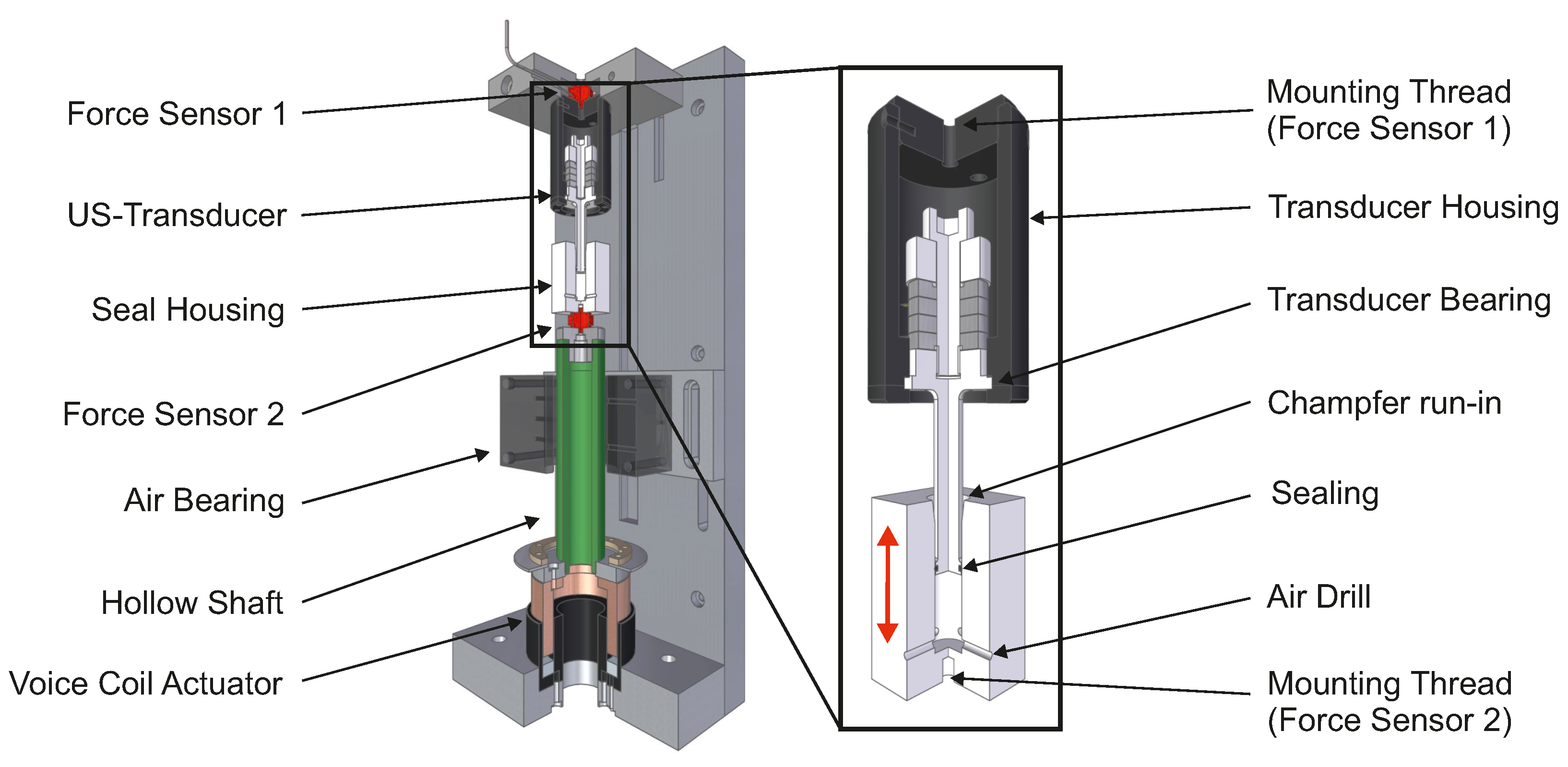
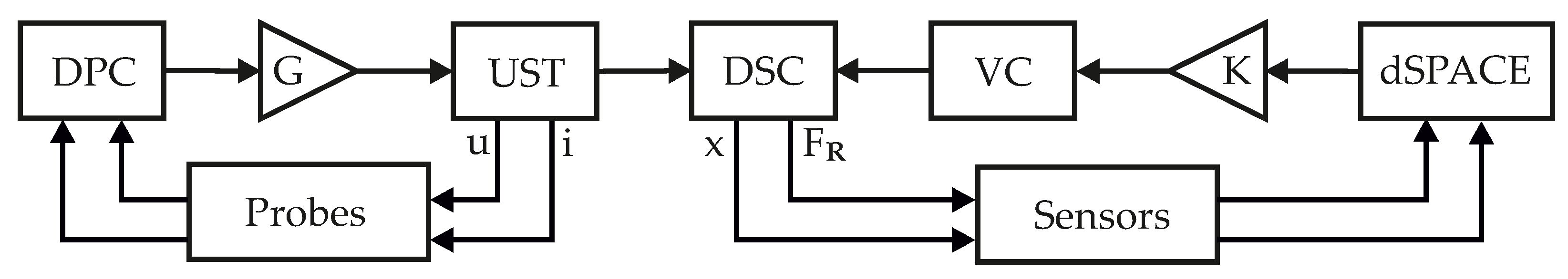
2.1. Topology of Linear Tribometer

The linear tribometer shown in Figure 1 is vertically aligned and is 525 mm high. The vertical alignment is used to prevent axial moments from leading to an uneven distribution of normal force. The sealing holder is mounted on a hollow shaft which is axially guided by an air bearing. The drive is performed by a linear voice coil actuator along the vertical axis. According to the working principle, the actuator provides forces linearly proportional to the current flow and independent from the voice coil position. This enables the measurement of frictional forces in the seal without additional dissipative forces caused by structural coupling with the test environment. The sonotrode tip of a Langevin type ultrasonic transducer is placed at the level of the sealing ring.
The transducer is mounted on top of the tribometer construction plate and could be exchanged. The differential force measurement is performed by piezoelectric force sensors applied on both sides of the examined contact, one between the sealing holder and the hollow shaft and one at the back of the ultrasonic transducer housing. The sealing holder designs for the piston and rod seal and the corresponding sonotrode tip designs are shown in Figure 1. According to their technical use in pneumatic cylinders, the piston and the shaft designs enable the investigation of friction effects under two different bearing conditions of the sealing ring concerning the inner and outer diameter. The drive control of the voice coil actuator is implemented through the real-time dSPACE controller board of type DS1103 and could be switched between speed control mode for the measurement of friction dynamics and force control mode for the identification of breakaway processes.
Figure 2 gives an overview of the control loops implemented to the tribometer. The US-transducer (UST) is operated in resonant mode by a digital phase control unit (DPC 500/100k) [16]. When driven in resonant mode, the velocity amplitude of the ultrasonic transducer is proportional to the current amplitude [17]. This is the reason why a simultaneously operating current controller is used to keep the velocity’s amplitude constant during a measurement run. The detection of amplitude and phase information between the driving signals current and voltage was done using phase sensitive demodulation (PSD) [18]. This information was further used to keep the system at resonance constantly with a PID-controller. This hardware was also used to determine the steady-state transducer’s electromechanical impedance, which means the absolute ratio of tip velocity to current. These measurements were additionally verified by laser vibrometer measurements. To ensure resonant operation of the UST and thus avoid instabilities of the control loop resulting from load-dependent increases of the system’s damping, the phase-zero-crossing of the mechanical admittance was used as an indicator for the resonance frequency. This required precise preliminary identification of the parallel capacitor Cp. Knowing this parameter, the phase of the mechanical admittance was calculated internally by compensation and used as the input variable of the phase control loop. The UST is driven by a wide-bandwidth, high-power audio amplifier (G). The displacement of the sealing holder, and in turn the dynamic sealing contact (DSC), is measured by a triangulation laser sensor and is used as feedback for the implemented PID position control. The reference displacement profile is obtained by integration of an in operationally-calculated velocity profile. The force signal from force sensor 1 (see Figure 1) is used as feedback to the implemented PID force controller. The classic controller was extended by feed-forward control. This required a preliminary measurement of the current–force characteristic of the voice coil motor (VC) with a static force sensor using a linearly increasing current signal covering the complete stroke of the motor. That way, the one-dimensional lookup table obtained was used to form the feed-forward value on the basis of the force feedback signal. A current controlled power amplifier (K) is used to drive the voice coil motor.

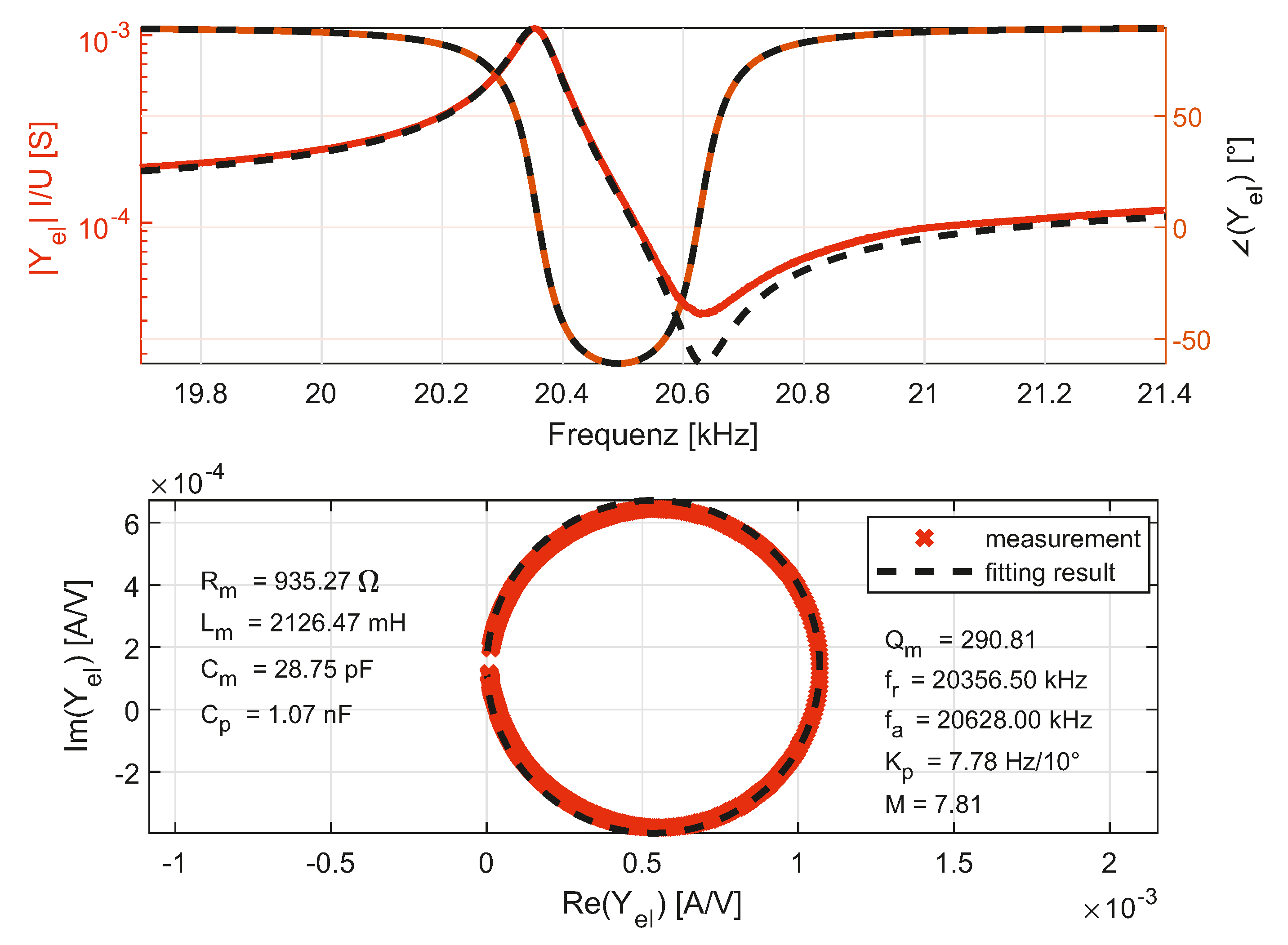
2.2. Ultrasonic Transducer Design

The design of the ultrasonic transducers used in the linear tribometer was based on the USDC ultrasonic shock drilling system developed by the Jet Propulsion Laboratory of NASA [19] due to its compact design and high vibration amplitudes, and the good linearity between the applied current and the vibration velocity. However, the original design was constructively optimized in terms of longevity through damping reduction and high amplitude for the oscillating systems. For example, the bolt used to preload the piezoceramics was designed together with the horn (sonotrode) as one part, which avoids the usual screw connection near the vibration node and thus unnecessarily high material stresses. The design of the bolt head (nut) has also been optimized with regard to dynamically occurring stresses at the bolted joint. Furthermore, a notch has been designed at the junction between the piezo package and the bearing near the node to protect the outer ceramic from any high stresses that may occur during operation outside the resonant frequency. The piezoceramics used are z-polarized PIC181 rings with a thickness of 5 mm, an outer diameter of 25 mm and an inner diameter of 16 mm. The transducer is operated resonantly in his respective longitudinal eigenmode at 20 kHz. After a rough calculation for the rod oscillator, further calculations regarding the choices of materials and the mass distributions of the oscillating structures were carried out with the institute’s in-house-developed 2D FE tool BekS based on the transfer matrix method [20]. The final geometric design was carried out with the help of CADFEM’s FE tool ANSYS Workbench [21]. A linear approach for the material damping was used. The properties of the piezoceramics have been taken into account by specifying appropriate matrices for stiffness, piezoelectricity and permittivity according to [22]. Figure 3 shows the structure and the normalized velocity distribution in the longitudinal direction along the length of the sonotrode. In addition, the design elements’ boundaries of the underlaid CAD model are shown as dashed lines. The titanium alloy Ti-6Al-4V was chosen for the transducer’s sonotrode. Due to the material’s high specific strength and hardness, it can be assumed that the contact surface remained in the same conditions for the complete investigation. For the investigation of the piston sealing, the groove at the tip of the sonotrode ensured that the seal always remained on the sonotrode tip while relative movements of the housing and sonotrode were performed. Thus, the ultrasonic velocity amplitude can be assumed to have remained constant in the contact area, on average. The designed transducer was characterized both electrically and mechanically by means of fitting of frequency response function measurements. Figure 4 shows the fitting results of the measured electrical admittance of the 20 kHz transducer. The identified parameters of the Butterwoth Van Dyke model are listed in the locus curve plot. Measurements of mechanical admittance by laser Doppler vibrometry revealed a ratio between vibration amplitude x ^ U S and driving current i ^ of 0.076 μm/mA. This means that a ratio of 9.7 m/As prevailed between the ultrasonic velocity v ^ U S and current i ^ . This ensured a wide bandwidth for the variation of the relative velocity in the friction contact.

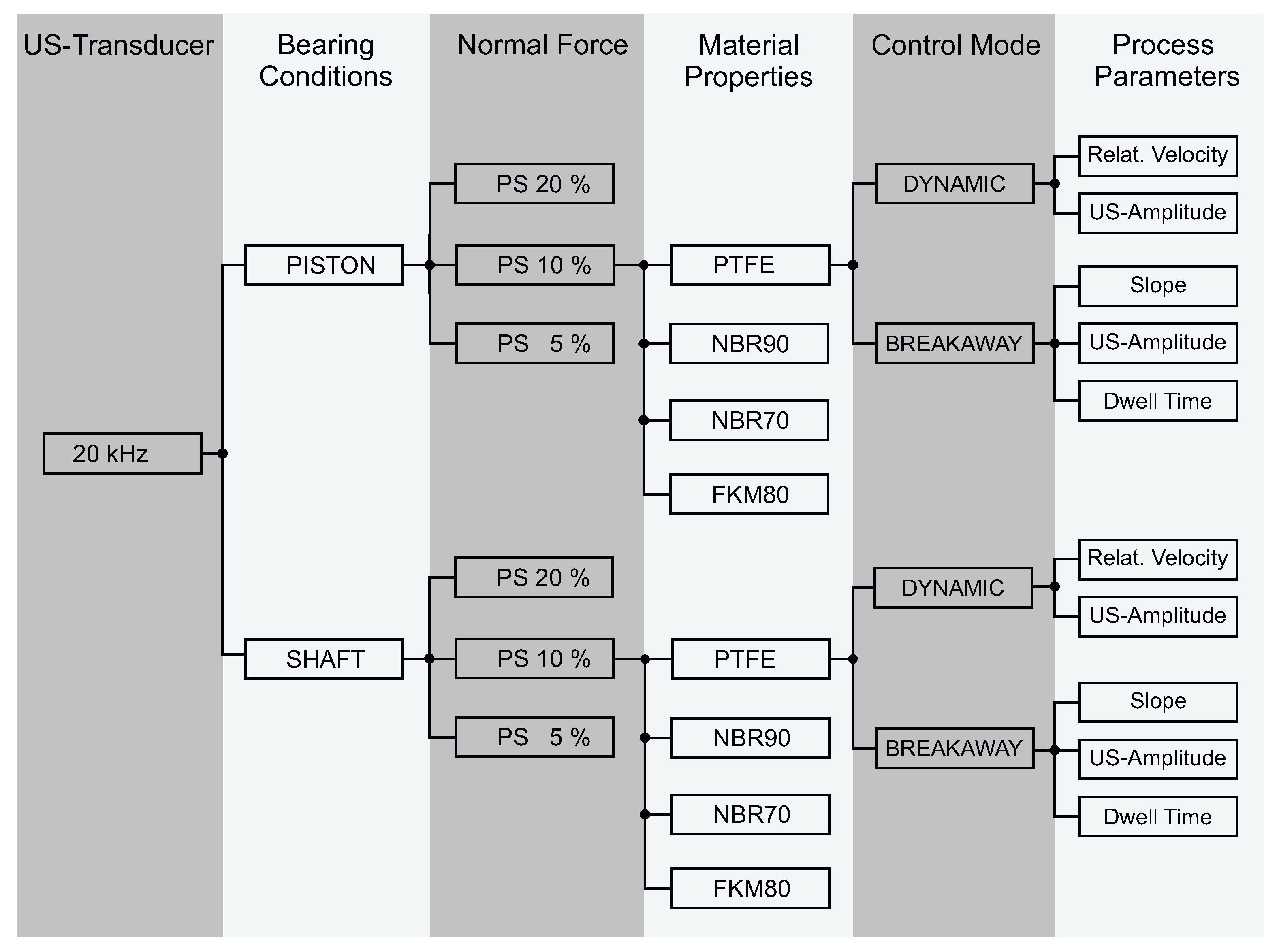
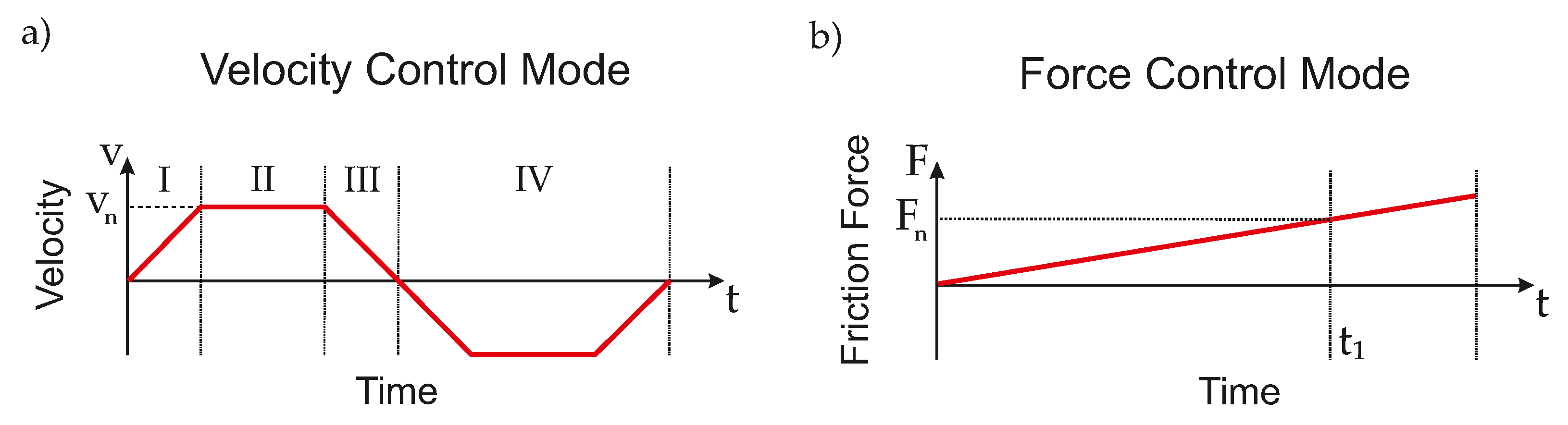
3. Design of the Experiment and Experimental Procedures

The investigation procedures required the implementation of two different control modes. The control of the velocity of the sealing holder allowed is to determine the sliding friction force under constant parameters. The force control was implemented for the identification of the breakaway force as a function of the ultrasonic amplitude and the sealing ring material.
Figure 5 shows the parameter tree for the investigation of contact behavior induced by a superposition of 20 kHz. The parameters are subdivided hierarchically from left to right and result from the mounting effort and error probability. A variation of the ultrasonic excitation frequency is associated with a change of the ultrasonic transducer and a subsequent realignment of the transducer’s sonotrode tip and the sealing holder. This is associated with a large amount of effort and a susceptibility to error during the alignment. Different results for the same measurement in piston and shaft operation modes define the bearing conditions of the sealing ring and are associated with the dismantling of the sealing holder and realignment with the US sonotrode. This is also true when the pre-stress of the sealing ring normalized to the initial cross section thickness (PS) is varied. The pre-stress changes the cord compression and thus the normal force in the contact. The play of the sealing ring in the groove is a further effect intermediately related to this parameter’s variation. The change of a sealing ring is associated with the disassembly of the transducer mounting block assembly group, without the disassembly and realignment of the US transducer. For the variation of the sealing ring material, the mounting effort is significantly reduced here. While the geometry of an o-ring with an inner diameter of 9 mm and a cord thickness of 1.5 mm remained the same due to symmetry and scalability reasons, the material of the examined sealing rings was chosen to cover a spectrum that includes solid materials from polytetrafluoroethylene (PTFE) with very low friction coefficients to stiff rubber materials with elasto-plastic properties. The fluorcarbon elastomer (FKM) was chosen due to its high thermal stability and its similar material properties to the nitrile butadiene rubber (NBR) with respect to the friction characteristics [23]. While having approximately the same glass transition temperature, the two materials differ in terms of their elasticity and viscoelastic properties, so they must be considered individually. Although FKM is resistant to environmental influences, it has low tear strength and abrasion resistance compared to NBR.
To continue with the investigation of breakaway transients after a measurement series of the dynamic contact behavior of a certain parameter set, only the control mode needs to be changed by a switch in the implemented software from velocity to force control mode. Ultimately, the traversing of the velocity and amplitude for ultrasonic vibrations induced for measurements of dynamic contact behavior was solved by software. Hence, the least effort and the least susceptibility to error were involved.
Preliminary investigations served to determine the limits of the experiment procedure. The maximal acceleration of the voice coil motor being reached while keeping the velocity set point in the tolerance range was a central limit factor. The maximal current by the US transducer which could be still stably controlled during the process was another limiting factor. Furthermore, the power amplifier used to drive the US transducer, and the maximal pre-stress resulting in high static friction forces in the contact area, are opposing factors and needed to be determined and provided with a certain reserve. Once the limits of the test parameters have been determined, the test procedure was worked out.

3.1. Identification of Dynamic Friction

The control of the velocity of the sealing holder allows one to determine the sliding friction force under constant parameters. A trapezoidal profile was chosen for this purpose, since such profiles each contain an area of constant velocity; see Figure 6a. Trapezoidal profiles are classified as C 0 differentiable, which means that they are continuous in their course, but not continuously differentiable. According to [24], this leads to a continuous and differentiable, i.e., a kink-free, course of displacement, classified as C 1 -continuous. These profile properties enable the use of a differentiated displacement signal as the feedback from a PID controller of the velocity. The longitudinal displacement is measured by a triangulation sensor against a reflective blisk mounted on the voice coil slider pushing forward the seal housing.
The friction force is only evaluated in area II. In order to make the best possible use of this area on the total range of 7 mm , the velocity profile was optimized with respect to the maximum acceleration of the test rig. In addition, this allows one to avoid the high-frequency oscillations described in [25], occurring at the jumps of the acceleration. Due to the point symmetry, area IV is identical to areas I–III and completes a motion cycle of the seal. The velocity-dependent friction force was obtained by averaging friction force values determined from bypassing area II over five cycles in the same test conditions. Furthermore, every measurement with a certain parameter set was repeated three times due to statistical deviations in the measured values. The repetitions did not take place sequentially, but were stochastically scattered to avoid systematic errors resulting from progressive abrasion of the sealing ring during the test series. This was also a means to prevent thermal effects from taking place with a rising US amplitude in the contact area. The inertial behavior of thermodynamic systems is a positive effect here, so a mean constant temperature can be assumed for a certain variation series here. Every sealing ring was conditioned preliminarily with and without ultrasonic vibrations by the defined traveling profile. Additionally, long term measurements were performed with each material used to define a state for the conditioning and examine the wear taking place with and without ultrasound.

3.2. Identification of Breakaway Transients
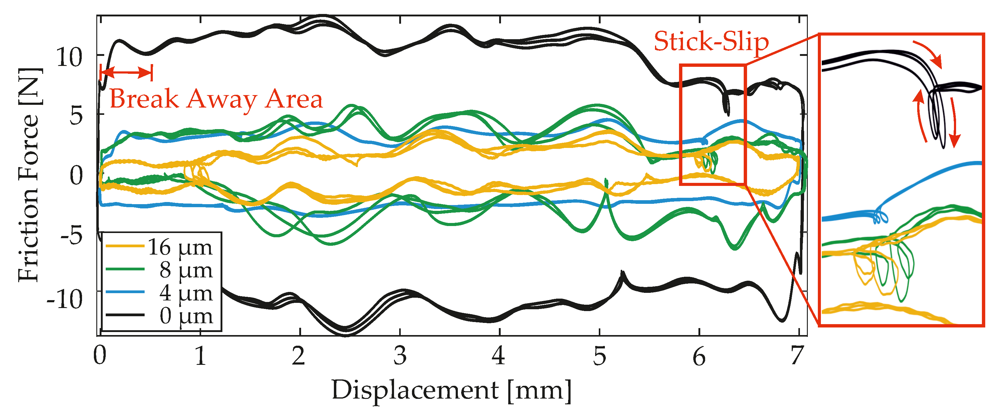
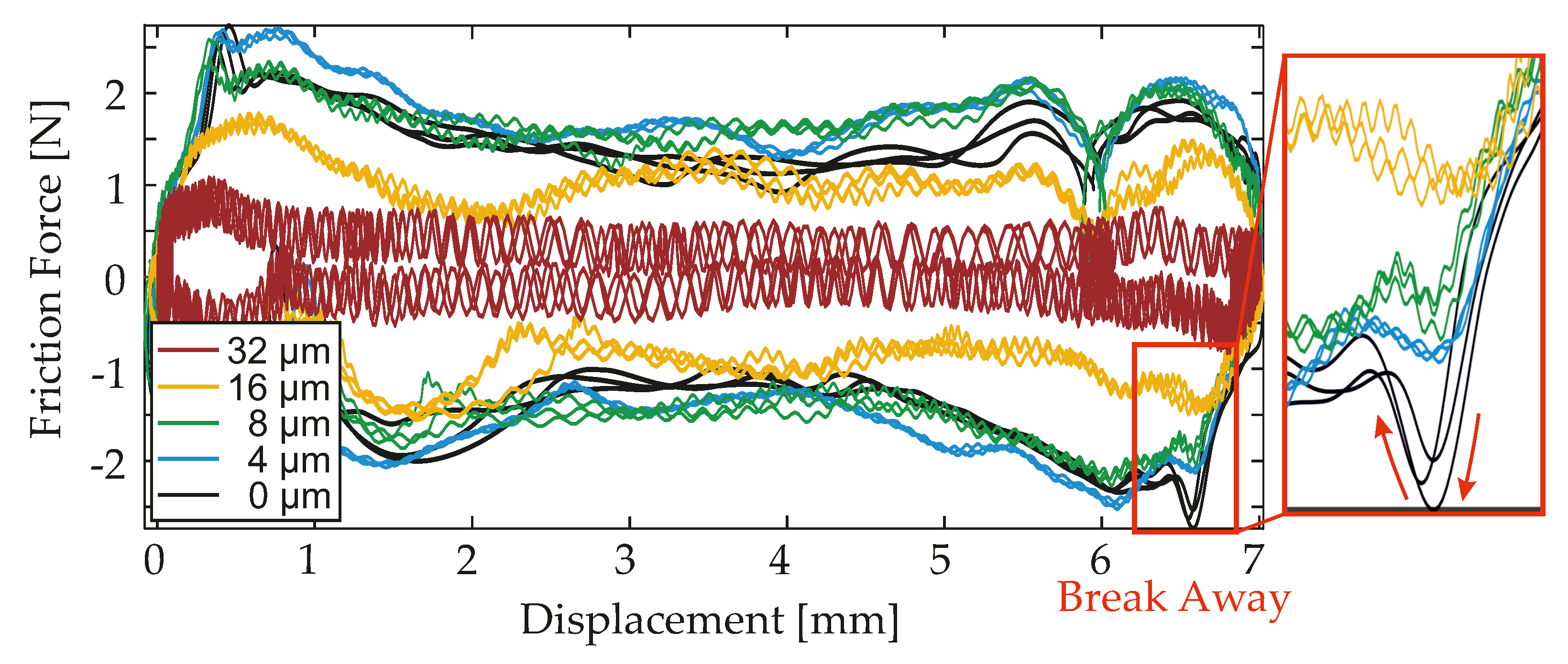
The force control was implemented for the identification of the breakaway force as a function of the ultrasonic amplitude and the sealing ring material. With the linearly increasing target force being applied to the sealing ring (see Figure 6b), the displacement signal was used to detect the breakaway force. Instead of the traversing velocity, the slope of the force ramp and the US amplitude were varied. F n and t 1 signify the longitudinally applied force and the time since standstill when the breakaway point was reached. This was the moment when the transition from sticking or pre-sliding to sliding in the metal-elastomer contact took place. Additionally, the impacts of adhesive forces on the breakaway dynamics were taken into account by a variation series of the dwell time before a force was applied in the longitudinal direction.

4. Results

4.1. Sliding Friction Force

Figure 7 shows the displacement-dependent frictional forces in contact with a PTFE seal during cyclic movement of the seal’s housing. US vibration amplitudes from 0 to 16 μm were applied. As the stiffness of PTFE is high compared to NBR and shows solid-like properties, the control accuracy in dynamic operation was very high and thus the dispersion of the results was minimized. A traversing velocity of 50 mm/s was used. Starting from the initial position (0 mm), the acceleration led to longitudinal compression in the contact until the static frictional forces were overcome, resulting in a sliding process. In this regard, a small deflection in the force signal of the reference measurement without an ultrasonic excitation (black curve) marks the transition from static to dynamic friction. It is therefore interpreted as the breakaway area. More detailed investigations of this behavior were carried out in Section 4.2. The loop that can be detected at a distance of approximately 6.2 mm describes the occurrence of a stick-slip movement and is displayed enlarged next to the graph. After reaching the reversal point at 7 mm, the sealing ring was moved back to its initial position. The subsequent tensile load on the sensor caused a jump to negative force values, followed by another breakaway area. With the return of the axis to its initial position, a cycle was completed. The relevant frictional force was determined with the areas of constant speed, which were at approximately 10 N for the case without superimposed ultrasonic excitation. The resulting frictional force value was obtained by averaging over several cycles. If the friction contact was excited into oscillations, the friction force was reduced by 71% with an amplitude of 4 μm. A doubling of the amplitude to 8 μm resulted in a reduction of approximately 70%, similar to that of the reference measurement. Only when the amplitude was doubled further to 16 μm was a reduction of 85% obtained. Due to the decreasing change in the reduction from 71% to 85% when the amplitude was quadrupled, asymptotic behavior regarding the friction reduction can be assumed for this material. A further increase of the amplitude thus only caused marginal improvements.
The curves in Figure 8 using NBR70 were generated under equivalent initial conditions regarding the velocity and ultrasonic frequency, but with varying ultrasonic amplitudes. The piston rod velocity was 50 mm/s, and the ultrasonic frequency was 20 kHz. The breakaway points are more pronounced due to the lower material stiffness and thus greater elongation of NBR70 compared to PTFE. The force increase is greater: the sudden drop in the transition from the static friction phase to the sliding friction phase is more pronounced than with PTFE. When ultrasonic excitation was applied with amplitudes of 4 and 8 μm, no significant reduction of the frictional forces could be determined. From 16 μm upwards, a reduction of 32% was achieved. The ultrasonic vibrations are clearly visible in the measured signal. The force–displacement profiles in Figure 8 have vibrational components superposed resulting from the contact dynamics in the range of nearly 100 Hz and the ultrasonic excitation. Due to the significant reduction in the frictional force that only started at 16 μm, the vibration amplitude increased to 32 μm. This caused a further reduction of up to 81%. In terms of stable thermal and kinetic operation conditions, a maximal amplitude of 16 μm was chosen for further experiments. With the investigation of the two materials, PTFE and NBR70, at a speed of 50 mm/s, the positive effects in terms of friction reduction at different ultrasonic amplitudes were clearly demonstrated. For a better understanding of the conditions within the breakaway area, the breakaway forces were measured with the use of force control.

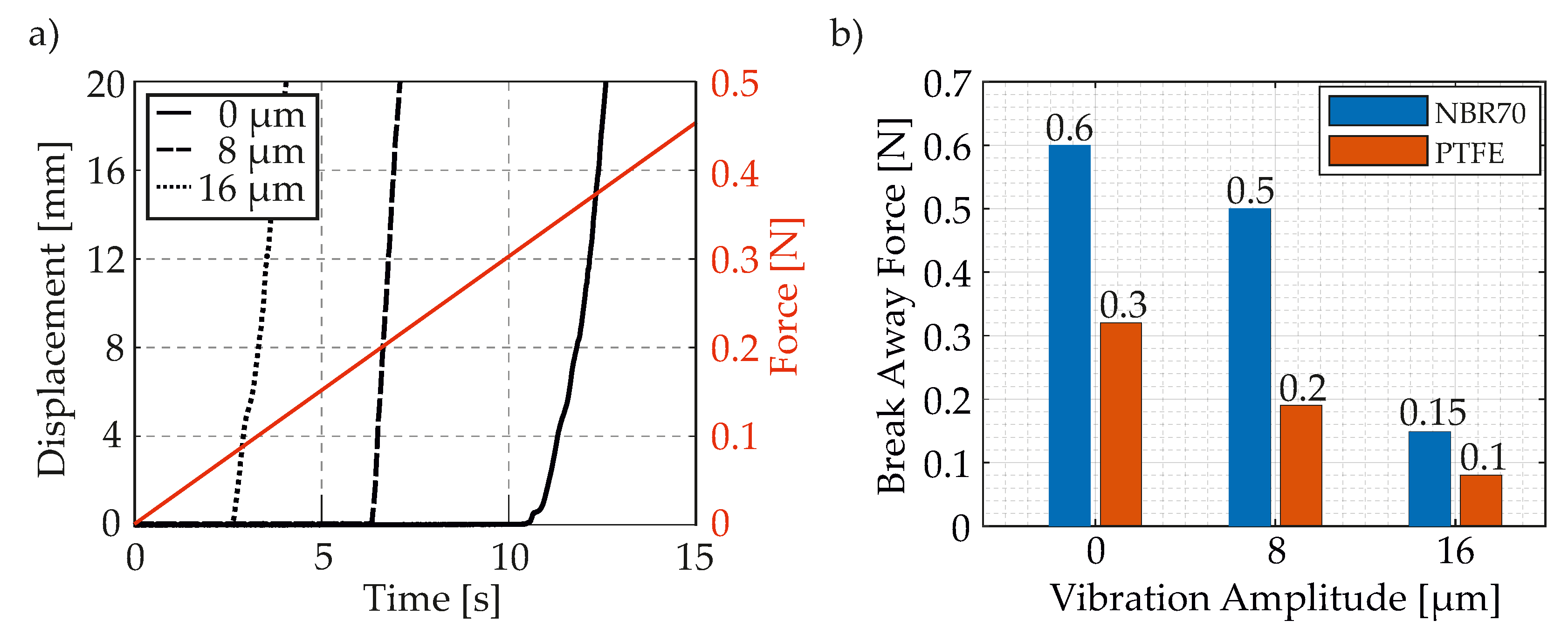
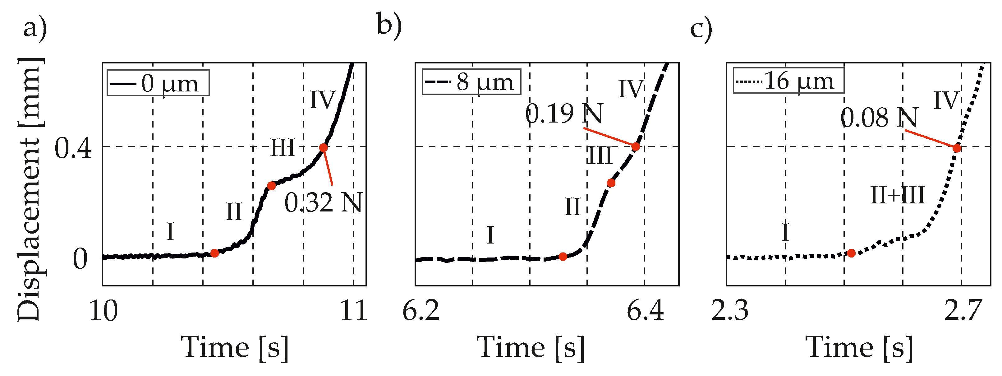
4.2. Breakaway Force

To identify the breakaway force, a force controller was designed to subject the sealing ring to a linearly increasing force. Therefore, the signal from one of the force sensors is used as feedback. The breakaway point can be identified by the movement of the sealing ring, which is detected by a displacement sensor. First, the breakaway force was investigated for PTFE. Due to the high stiffness of the material and thus the modesty of its dynamics, the settings of the controller’s parameters were very simple. The increasing force and the displacement signals are shown in Figure 9a. The slope was set to a value of 0.03 N/s for the sake of a good identification of the characteristic movement of the sealing ring on the metal surface. The displacement was measured at different ultrasonic amplitudes. The excitation of the contact partners led to earlier breakaway of the seal, i.e., with a lower breakaway force. The sliding process of the seal was stopped after approximately 12 mm due to a current or movement limitation in order to protect the components of the test rig from damage. At the time of breakaway, the value of the force, and thus the breakaway force, was determined; see Figure 9b. For an exact determination of the breakaway force, it was necessary to consider the characteristic movement of the sealing ring in the groove; see Figure 10a–c.
In the ranges I, II and III, static friction is still present. The change in the displacement signal can be explained by the movement of the sealing ring in the groove and its elongation as a result of the static friction force. With the aid of a transparent housing, this displacement could be determined as 0.4 mm for PTFE and 0.6 mm for NBR70; see Figure 11a,b. Thus, sliding friction did not prevail until area IV. The transition from area III to area IV can be identified as the breakaway point. The breakaway force of 0.3 N (without ultrasonic excitation) could already be reduced by 33% with a vibration amplitude of 8 μm. An increase to 16 μm resulted in a reduction of the breakaway force by 67%. With NBR70 as the seal’s material, far higher amplitudes were necessary for significant reductions of the breakaway force. The initial breakaway force of 0.6 N could only be reduced by 17% at a vibration amplitude of 8 μm. A reduction of 75% could be achieved at a vibration amplitude of 16 μm. As already seen in dynamic operation mode in Section 4.1, a higher excitation amplitude was needed for softer materials to cause a significant effect.

5. Conclusions and Future Work

The introduced tribometer enables the precise quantitative identification of frictional characteristics of seals exposed to ultrasonic vibrations with high reproducibility. Furthermore, the implemented control loops enable the individual analysis of dynamic friction behavior and breakaway transients. It was demonstrated that the force controller of the voice coil motor was indispensable for the detection of breakaway transients, and thus of stick-slip transitions. The presented tribometer is easily scalable for different seal geometries and parameter sets. A detailed investigation of the effect of ultrasonic friction reduction with respect to the key excitation and system parameters is going to be carried out in future. Investigations of material wear under US vibrations will be carried out as well. The experiments carried out demonstrated technical limits that can be used when seals are designed for pneumatic actuators. The validation of a common model, describing the dynamic and transient behavior of the US transducer and the seal contact, was completed with the experimental results. By this means the application of a model-based friction control in pneumatic sealing ring contacts was approached.

Author Contributions

Conceptualization, M.W., C.N., J.T. and J.W.; methodology, M.W. and C.N.; software, M.W. and C.N.; validation, M.W. and C.N.; formal analysis, M.W. and C.N.; investigation, M.W. and C.N.; data curation, M.W. and C.N.; writing—original draft, M.W. and C.N.; writing–review and editing, M.W., C.N., J.T. and J.W.; visualization, M.W. and C.N.; supervision, J.W.; project administration, M.W.; funding acquisition, J.W. and J.T. All authors have read and agreed to the published version of the manuscript.

Funding

The research project entitled Reduction of the breakaway force in the pneumatic cylinder using ultrasonic vibrations was funded by the German Research Foundation (DFG) under the research number TW75/3-1. The publication of this article was funded by the Open Access Fund of the Leibniz Universität Hannover. The authors would like to thank them for the support.

Institutional Review Board Statement

Not applicable.

Informed Consent Statement

Not applicable.

Data Availability Statement

Some or all data generated or used during the study are available from the corresponding author by request.

Acknowledgments

The research project entitled “Reduction of the breakaway force in the pneumatic cylinder using ultrasonic vibrations” was funded by the German Research Foundation (DFG) under the research number TW75/3-1. The authors would like to thank them for the support.

Conflicts of Interest

The authors declare no conflict of interest.

References

  1. Gao, H.; Zhu, D.; Bao, G.; Xiao, C.; Cheng, T. Ultrasonic friction reduction investigation on a longitudinal-vibration-mode pneumatic cylinder. In Proceedings of the International Conference on Fluid Power and Mechatronics (FPM), Harbin, China, 5–7 August 2015; pp. 426–430. [Google Scholar]
  2. Siegert, K.; Ulmer, J. Reduction of sliding friction in wire and tube drawing with ultrasonic waves. Prod. Eng. 1998, 5, 9–12. [Google Scholar]
  3. Littmann, W.; Storck, H.; Wallaschek, J. Sliding friction in the presence of ultrasonic oscillations: Superimposing of longitudinal oscillations. Arch. Apllied Mech. 2001, 71, 549–554. [Google Scholar] [CrossRef]
  4. Popov, V.L.; Starcevic, J.; Filippov, A.E. Influence of Ultrasonic In-Plane Oscillations on Static and Sliding Friction and Intrinsic Length Scale of Dry Friction Processes. Tribol. Lett. 2010, 39, 25–30. [Google Scholar] [CrossRef]
  5. Bharadwaj, S. Active Friction Control via Piezoelectrically Generated Ultrasonic Vibrations. Ph.D. Thesis, The Ohio State University, Columbus, OH, USA, 2009. [Google Scholar]
  6. Pohlmann, R.; Lehfeld, E. Influence of Ultrasonic Vibration on Metallic Friction. Ultrasonics 1966, 4, 178–185. [Google Scholar] [CrossRef]
  7. Storck, H.; Littmann, W.; Wallaschek, J.; Mracek, M. The effect of friction reduction in presence of ultrasonic vibrations and its relevance to travelling wave ultrasonic motors. Ultrasonics 2002, 40, 379–383. [Google Scholar] [CrossRef]
  8. Kapelke, S.; Seemann, W. On the Effect of Longitudinal Vibrations on Dry Friction: Modelling Aspects and Experimental Investigations. Tribol. Lett. 2018, 66–79. [Google Scholar] [CrossRef]
  9. Kumar, V.; Hutchings, I.M. Reduction of the sliding friction of metals by the application of longitudinal or transverse ultrasonic vibration. Tribol. Int. 2004, 37, 833–840. [Google Scholar] [CrossRef]
  10. Gao, H.; Volder, M.D. A Pneumatic Actuator Based on Vibration Friction Reduction with Bending/Longitudinal Vibration mode. Sens. Actuators 2016, A 252, 112–119. [Google Scholar] [CrossRef]
  11. Pham, T.M.; Twiefel, J. Ultrasonic Friction Reduction in Elastomer-Metal Contacts and Application to Pneumatic Actuators. Phys. Procedia 2015, 70, 55–58. [Google Scholar] [CrossRef] [Green Version]
  12. Dong, S.; Dapino, J.M. Dynamic System Model for Ultrasonic Lubrication in Perpendicular Configuration. Ultrasonics 2017, 75, 98–105. [Google Scholar] [CrossRef] [PubMed] [Green Version]
  13. Shoyama, T.; Fujimoto, K. Calculation of high-frequency dynamic properties of squeezed O-ring for bearing support. Mech. Eng. J. 2018, 5, 17-00444. [Google Scholar] [CrossRef] [Green Version]
  14. Shoyama, T.; Fujimotob, K. Direct measurement of high-frequency viscoelastic properties of predeformed Rubber. Polym. Test. 2018, 67, 399–408. [Google Scholar] [CrossRef]
  15. Bogoslovov, R.B.; Rolanda, C.M.; Gamache, R.M. Impact-induced glass transition in elastomeric coatings. Appl. Phys. Lett. 2007, 90, 221910. [Google Scholar] [CrossRef] [Green Version]
  16. Ille, I.; Twiefel, J. Model-Based Feedback Control of an Ultrasonic Transducer for Ultrasonic Assisted Turning Using a Novel Digital Controller. Phys. Procedia 2015, 70, 63–67. [Google Scholar] [CrossRef] [Green Version]
  17. Mojrzisch, S.; Twiefel, J. Phase-controlled frequency response measurement of a piezoelectric ring at high vibration amplitude. Arch Appl. Mech. 2016, 86, 1763–1769. [Google Scholar] [CrossRef]
  18. Chen, D.; Yang, W.; Pan, M. Design of Impedance Measuring Circuits Based on Phase-Sensitive Demodulation Technique. IEEE Trans. Instrum. Meas. 2011, 60, 1276–1282. [Google Scholar] [CrossRef]
  19. Bao, X.; Bar-Cohen, Y.; Chang, Z.; Dolgin, B.P.; Sherrit, S.; Pal, D.S.; Du, S.; Peterson, T. Modeling and Computer Simulation of Ultrasonic/Sonic Driller/Corer (USDC). IEEE Trans. Ultrason. Ferroelectr. Freq. Control. 2003, 50, 9. [Google Scholar]
  20. Wurpts, W.; Bruns, P.; Twiefel, J. A transfer matrix method for the design of resonant piezoelectric devices. In Proceedings of the International Workshop on Piezoelectric Materials and Applications in Actuators, Hannover, Germany, 14–17 July 2013. [Google Scholar]
  21. ANSYS Homepage. Available online: https://www.ansys.com/ (accessed on 28 June 2021).
  22. PI Ceramic Material Data. Available online: https://www.physikinstrumente.de/fileadmin/user_upload/physik_instrumente/files/datasheets/PI_Ceramic_Material_Data.pdf (accessed on 4 July 2021).
  23. Mofidi, M.; Prakash, B. Frictional behaviour of some sealing elastomers in lubricated sliding. In Proceedings of the 15th Nordic Symposium on Tribology—NordTrib, Trondheim, Norway, 12–15 June 2012. [Google Scholar]
  24. Biagiotti, L.; Melchiorri, C. Trajectory Planning for Automatic Machines and Robots, 1st ed.; Springer Science & Business Media: Berlin/Heidelberg, Germany, 2008; pp. 72–76. [Google Scholar]
  25. Constantinescu, D.; Croft, E.A. Smooth and Time-Optimal Trajectory Planning for Industrial Manipulators along Specified Paths. J. Robot. Syst. 2000, 17.5, 233–249. [Google Scholar] [CrossRef]
Figure 1. Topology of the linear tribometer. Sealing holder design for piston sealing and the corresponding sonotrode tip design.
Applsci 11 06289 g001
Figure 2. Control loops implemented in the novel tribometer.
Applsci 11 06289 g002
Figure 3. (a) Structure of the ultrasonic transducer. (b) Longitudinal velocity distribution.
Applsci 11 06289 g003
Figure 4. Fitting results of the measured electrical admittance for the 20 kHz transducer.
Applsci 11 06289 g004
Figure 5. The parameter tree for the investigation of contact behavior induced by ultrasonic superposition of 20 kHz.
Applsci 11 06289 g005
Figure 6. The velocity profile for the investigation of sliding friction force (a) and the force profile for the identification of breakaway force (b).
Applsci 11 06289 g006
Figure 7. Force−displacement curves for PTFE at v rel of 50 mm/s.
Applsci 11 06289 g007
Figure 8. Force−displacement curves for NBR70 at v rel of 50 mm/s.
Applsci 11 06289 g008
Figure 9. (a) Displacement at varying US amplitudes with a linear force profile; (b) resulting breakaway forces for PTFE and NBR70.
Applsci 11 06289 g009
Figure 10. Breakaway phases (I–IV) in the displacement course of the PTFE sealing with a feed force increasing with 0.03 N/s for a superposed ultrasonic amplitude of 0 µm (a), 8 µm (b) and 16 µm (c).
Applsci 11 06289 g010
Figure 11. (a) Validation of the assumed movement of the seal with a transparent glass housing. (b) Schematic of movement and elongation of the seal at the breakaway point in the groove.
Applsci 11 06289 g011
Publisher’s Note: MDPI stays neutral with regard to jurisdictional claims in published maps and institutional affiliations.

