Article

Fault Current and Voltage Estimation for Pole-to-Pole Faults in Modular Multilevel Converter Based DC Grids Considering AC Active Power

1
State Grid Jiangsu Electric Power Co. Ltd., Economic Research Institute, Nanjing 210008, China
2
Department of Electrical Engineering, Zhejiang University, Hangzhou 310058, China
*
Author to whom correspondence should be addressed.
Appl. Sci. 2021, 11(6), 2882; https://doi.org/10.3390/app11062882
Submission received: 1 March 2021 / Revised: 18 March 2021 / Accepted: 19 March 2021 / Published: 23 March 2021
(This article belongs to the Special Issue Power Electronics in Power Networks)

Abstract

:
DC short-circuit faults are one of the challenges for modular multilevel converter (MMC) based DC grid. It is vital for proper design of protection system to estimate the fault currents and voltages. The existing calculation methods based on RLC equivalent model of MMC have enough accuracy in estimating the branch currents but suffer from poor accuracy in estimating the node voltages. To better reflect the dynamics of MMC control during the fault, MMC is equivalent to a RLC series circuit in parallel with a variable controlled current source. This model not only considers the discharge of sub-module capacitors but also the AC active power and MMC control. Then, based on the discrete adjoint model of the equivalent MMC model and the RL series equivalent model of DC lines, the fault voltages and currents for the pre-fault and faulted DC grids could be easily obtained. From the aspect of power balance, the importance of AC active power on estimating the fault currents and voltages is discussed then. At last, based on the Zhangbei bipolar DC grid, comparisons are conducted between the simulations on PSCAD, the numerical calculation under the proposed method and the existing methods. The results show that the proposed method and the existing methods are both able to accurately estimate the fault currents within a relative error of 1%. However, compared with the error of the existing methods in calculating the fault voltages, the relative error for the proposed method is limited to less than 5% for the whole DC gird.

1. Introduction

High-voltage large-capacity flexible DC transmission, with its advantages of controllable trend, easy to absorb new energy, and ability to provide reactive power support, has become an important pillar of the future DC grid [1,2,3,4]. Among the various topologies, modular multi-level (MMC) converter is the preferred topology due to the advantages of high scalability and low harmonic [5].
The short-circuit fault is one of the critical contingencies for an AC/DC hybrid system. One of the shortcomings for the half-bridge sub-module structure is that it does not have the ability to clear DC faults, and it needs to be equipped with DC circuit breakers to isolate the fault line [6,7,8]. The fault current generated during this period is harmful and critical for the secure and safe operation of DC grid. For properly design of fault current limiting and fault blocking devices, an accurate calculation method of fault current and voltage is very necessary [9,10].
The traditional short-circuit transient characteristic calculation method for DC grid is electromagnetic transient (EMT) simulation [11,12,13,14]. However, this method suffers from low efficiency and high computation burden. In [15], a generic calculation method for pole-to-pole short-circuit fault currents in DC grids is proposed. Based on the simplified RLC equivalent of MMC, it presents a simple numerical analysis. Literature on MMC modeling shows that the minimum required complexity for dynamic MMC modeling has to include the outer controllers and partial dynamics [16,17]. In [18], relying on the modified averaged value models, DC fault current simulation is performed for protection design in radial multi-terminal DC systems. In [19], the dynamic analysis is carried out for voltage source converter based multi-terminal DC grids (VSC-MTDC) in order to analytically design a generalized feedback for DC voltage droop control. Although, converter outages and communication loss are considered, the article does not analyze line outages or DC faults. To improve the efficiency of the calculation method, MMCs are equivalent to RLC series circuits and the phase-mode conversion method is adopted to simplify the model of the whole DC grid in [20]. However, when the DC grid is radial or mesh, there are some difficulties in performing this method. In [21], the effect of the AC side on the DC short-circuit current is considered, and it provides accurate estimation for short-circuit currents. However, since the influence of MMC control is not considered, there are still some errors in estimating the fault currents and fault voltages. In [22,23], the accuracy for all the node voltages and branch currents could be improved by the inclusion of MMC controllers. However, the equivalent current sources for converters in the active power control are treated as constant. However, the active and reactive power take changes very sharply especially several milliseconds after the pole-to-pole fault. Therefore, the assumption that the active power keeps constant during the fault leads to some bias especially in estimating the node voltages. Therefore, to guarantee enough accuracy, the dynamics of the AC active power should be involved.
This paper makes in-depth analyses of the AC active power on the transient characteristics. From the perspective of the power balance, it is proved that the deviation of AC power results in a relatively large error in calculating the node voltages. Fortunately, the real-time transmitted AC active power and the dynamics of the MMC controllers can be reflected through improving the model of MMC. Based on this, a MMC is equivalent to a RLC series circuit in parallel with a variable controlled current source. Next, the whole DC grid is discretized by the discrete adjoint model. By this method, the dynamics of the controllers can be easily included. At last, the formulas and solutions for the matrices describing the relationship between the branch currents and the node voltages are given. Thus, a general method for estimating the branch currents and node voltages is established.
The features and contributions of this paper are as the follows. (1) The influence of the AC active power on estimating the node voltages and branch currents is fully analyzed. The absence of the AC active power will lead a wrong conclusion that the DC voltage of the inverter station rises after the fault. The deviation of AC active power will lead to small bias in estimating node voltages. (2) Instead of adopting the constant equivalent current sources for converters in the active power control mode, variable current sources are used to model the control dynamics of MMCs in active power modes. The accuracy in estimating the node voltages could thus be improved.
The rest of this paper is organized as follows. Section 2 equivalents MMC to a RLC series model in parallel with a variable current source taking into account the MMC controllers and the AC active power. Section 3 establishes the equivalent model for the whole DC grid based on the discrete adjoint model. Section 4 gives the pre-fault and faulted matrices describing the node voltages and branch currents, and a general method for calculating the transient voltages and currents is proposed. Section 5 verifies the accuracy of the proposed method. Section 6 draws the conclusions.

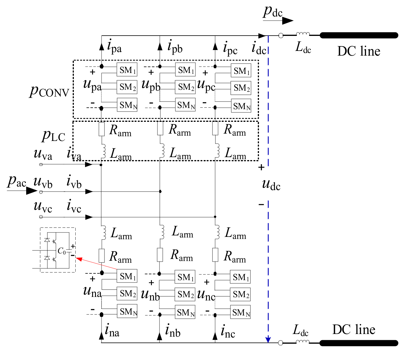
2. The Equivalent Model of MMC Considering AC Side Power and MMC Control

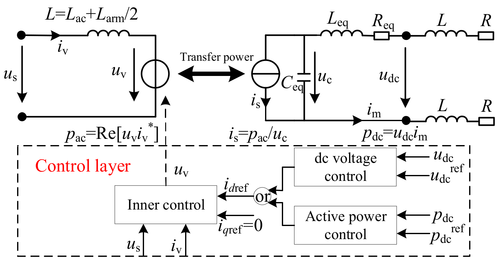
2.1. The Impact of AC Active Power and MMC Controllers

The basic structure of the MMC is illustrated in Figure 1. The converter consists of six arms, and the upper and lower arm in the same phase form a phase unit. Each arm consists of two parts, i.e., N series-connected identical sub-modules (SMs) and an arm inductor Larm. The equivalent arm resistor and the SM capacitor are denoted as Rarm and C0, respectively. The smoothing reactor is denoted as Ldc.
Here in Figure 1, urj and irj are the arm voltage and the arm current, where j (j = a, b, c) denotes phase and r (r = p, n) denotes the upper or lower arm. ivj is the MMC AC output current in phase j. uvj is the AC voltage at the point of common coupling (PCC) in phase j. udc is the DC voltage, and idc is the DC current.
At any time instant, the instantaneous power pdc at the DC terminal is the sum of the instantaneous AC active power at the AC terminal pac, the instantaneous powers resulting from the derivative of energy of the phase reactors pL and the module capacitors pCONV. Here, the phase reactor losses and converter losses are neglected. The relationship could then be described in Equation (1):
p d c = p a c + p + L C O N V
From the above equation, accurately estimating the branch currents and node voltages requires the equivalent MMC model well to reflect the power balance in the transient excursion. pCONV results from the variation in time of the controlled voltage, which is also the voltage across the module capacitor. In steady-state, this voltage is equal to the DC voltage at the terminal of the MMC. In transient excursion, the controlled DC voltage might be different from the terminal DC voltage due to the action of the controllers. Therefore, pCONV has to be estimated differently based on DC control mode and the terminal DC voltage during the transient.

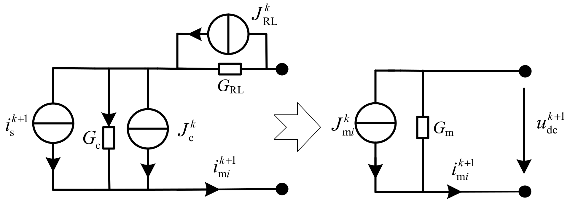
2.2. The Equivalent MMC Model Considering AC Active Power and MMC Controllers

In the generic RMS model, the equivalent MMC model is shown in Figure 2 [24]. The behavior of the MMC on the DC side is equal to a controlled current source is. The effect of pac is reflected by the controlled current source. The part of pCONV estimated by the terminal DC voltage is reflected in the derivative of energy of the equivalent capacitance. Similarly, the power from the derivative of energy of the equivalent inductance and equivalent resistance is pLC. The expression of the controlled current source, the equivalent capacitance, inductance and resistor is given in Equation (2).
i s = p ac u c , L eq = 2 3 L arm , R eq = 2 3 R arm ,   C eq = 6 C 0 N
where pac is power transmitted from the AC side. uc is the voltage across the equivalent capacitor.
However, the controlled DC voltage is absent in this model, that is, pCONV related to the DC control mode is not involved. Since MMC controllers take effect during the fault, the control mode would affect the output voltage on the AC side of MMC and then the transient characteristics of the DC side. However, the control strategy of the DC side could be implemented via the controlled DC voltage as a constituent component of the controlled arm voltages. That is, taking into account the control mode in computing the output voltage uv, the unaccounted power could be compensated by this improvement.
According to the nearest level modulation (NLM) strategy [25,26], MMC AC output voltage could be calculated as follows.
u v j t = m 2 v c o n * t 0 s i n ω t + φ j t 0 d c v c o n * t 0 = v d ref * 2 t 0 + v q ref * 2 t 0 φ j t 0 = a r c t a n v q ref * t 0 v d ref * t 0 {
where, m is the modulation ratio of the converter. ω is the angular frequency of the AC side. vdref* and vqref* are the outputs of the inner loop current controller.φj is the phase difference between the MMC AC output voltage and the AC voltage in phase j. t0 represents the last moment.
Then the power injected into the converter from the AC side could be computed as follows:
p a c = 3 u s j u v j X s + 0.5 X a r m s i n φ j
From Equations (3) and (4) and Figure 2, it could be seen that the DC control mode affects the MMC AC output voltage and then the AC active power. In fact, the AC active power and MMC control influence the discharge of submodule capacitors and thus the DC transient voltages and currents, which could roughly be estimated as follows.
It is assumed there is an error Δpac in estimating the AC active power. Then the error in estimating the controlled current source would be Δis = Δpac/uc. Here, it is assumed that the voltage of the capacitors is equal to the DC voltage terminal of the MMC. Then the error in node voltages would be
Δ u d c u c Δ i s C e q = Δ p a c C c e q Δ p a c C d c e q
For a DC grid, Ceq is typically hundreds to thousands μF. udc is usually hundreds to thousands kV. Then an error of several hundred MW in pac would lead an error of several dozen kV/ms in Δudc. In several ms after the fault, the error in fault voltages would be several dozen kV.
The error in estimating the branch currents could be evaluated from the deviation of line currents. Let u1, u2 and iL be the voltages and current of the line, and then the error would be
Δ i L Δ u 1 Δ u 2 L
The line inductance L is typically several hundreds to thousands mF. Taking into account the errors in fault voltages, the maximum estimation bias in ΔiL would be less than one kA/ms. Then in several ms after the fault, the maximum error in iL would be about one kA.
In summary, by combining the control strategy with the controlled current source, the power balance is well expressed. And not only the branch currents but also the node voltages could be estimated accurately by the improved equivalent MMC model shown in Figure 2.

2.3. The Model of MMC Controllers

The control strategy of MMC is relatively mature. In this paper, the classic inner and outer loop control methods are used for calculation [4,27,28]. The specific control algorithm is not repeated in this article. All variables in Equations (7)–(9) are unit values. The positive direction of the AC currents is injecting into the converter.
For the station with constant power control, the instantaneous expression of the outer loop controller is:
Δ p * t = P ref * p * t i kp * t = k pp Δ p * t i k i * t = k i p Δ p * t + Δ p * t 0 Δ t / 2 + i k i * t 0 i dref * t = i kp * t + i k i * t i q r e f * t = 0
For the station with constant voltage control, the instantaneous expression of the outer loop controller is:
Δ u dc * t = U dcref * u dc * t i kp * t = k p u Δ u dc * t i k i * t = k i u Δ u dc * t + Δ u dc * t 0 Δ t / 2 + i k i * t 0 i dref * t = i kp * t + i k i * t i q r e f * t = 0
where, kpp, kip and kpu, kiu are proportional and integral coefficient of constant power controller and constant voltage controller, respectively. udcref* is the reference value of DC voltage. pref* is the reference value of active power. p* is the instantaneous value of active power. idref* is the reference current of d-axis, iqref* is the reference current of q-axis.
The expression of the inner loop controller is:
Δ i d * t = i d r e f * d * Δ i q * t = i q r e f * q * Δ v d k p * = p 2 d * Δ v d k i * i 2 Δ i d * t + Δ i d * t 0 / d k i * 0 Δ v q k p * = p 2 q * Δ v q k i * i 2 Δ i q * t + Δ i q * t 0 / q k i * 0 v d r e f * d * d k p * d k i * * q * v q r e f * q * q k p * q k i * * d * {
where, kp2 and ku2 are the proportional and integral coefficients of the inner loop controller. id* and iq* are the d-axis and q-axis of the AC current. ud* and uq* are the d-axis and q-axis of the AC voltage us.

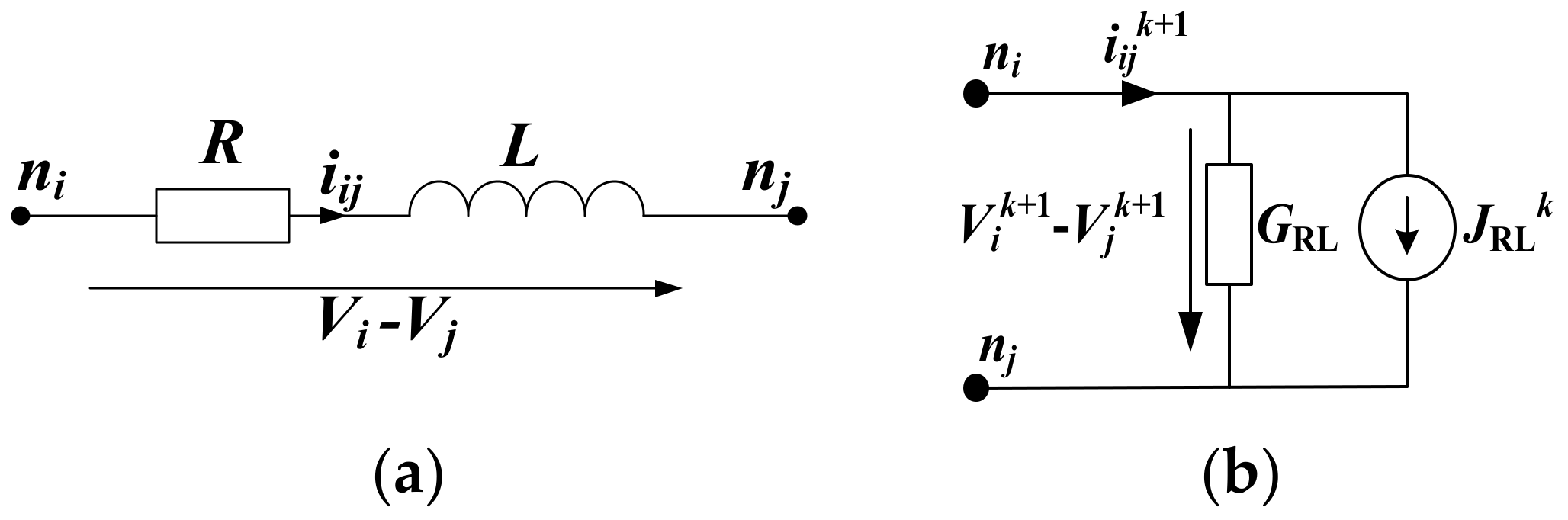
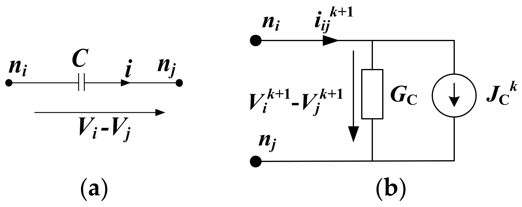
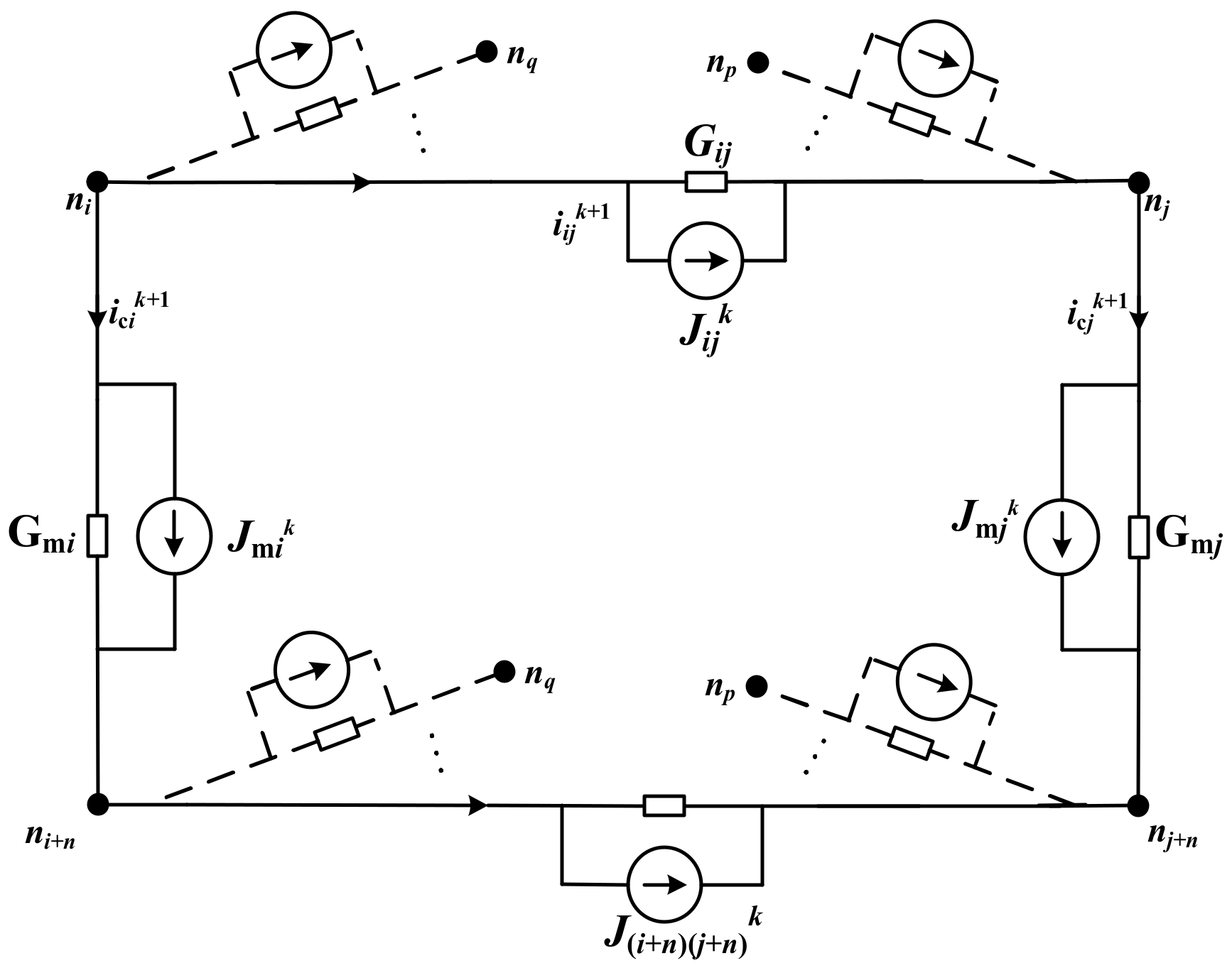
3. Discrete Adjoint Model of DC Grid

The characteristic of discrete adjoint model is that the lumped parameter element is converted into a parallel connection of an admittance and a current source according to the state of its history voltage and current. Thus, a circuit network originally described by differential-algebraic equations could be transformed into a network that could only be described by algebraic equations [4].
The discrete adjoint model of the series-connected resistor-inductor branch is shown in Figure 3, and the corresponding voltage and current characteristics are listed in Equation (10).
i i j k + 1 = G RL V i k + 1 V j k + 1 + J RL k G RL = h / L + h R J RL k = L i i j k / L + h R
where, h is the time step. L is the inductance of the branch; R is the resistance of the branch. The superscript k indicates the current step, and the superscript (k + 1) indicates the next step. i is the branch current. V is the node voltage. GRL is the equivalent admittance, and JRL is the equivalent current source.
The discrete adjoint model of the capacitor branch is shown in Figure 4, and the corresponding voltage and current characteristics are shown in Equation (11).
i i j k + 1 = G C V i k + 1 V j k + 1 + J C k G C = C / h J C k = - C V i k V j k / h
where, GC is the equivalent admittance and JC is the equivalent current source. The other variables have been defined as above.
By replacing the MMC equivalent circuit with the discrete adjoint model of the basic components, the discrete adjoint model of an MMC could be obtained, as shown in Figure 5.
Combing Equations (10) and (11) with the KVL and KCL laws:
i m i k + 1 = G m i u dc k + 1 + J m i n G m i = 1 / L eq h + R e q + h C eq J m i n = u c n L eq h i dc n h C eq i s n + 1 / L eq h + R e q + h C eq
In a large-scale DC grid, the overhead transmission lines are used to deliver bulk power over a long distance. The DC overhead lines are represented as a RL series circuit. The smoothing reactor on both sides of the MMC could be involved into the equivalent model of the lines. As shown in Figure 2, R represents the equivalent resistance of the DC line and L represents the DC reactor.
All MMC converters can be equivalent to RLC series circuits parallel with the controlled current sources, and DC lines can be equivalent to RL series circuits. On this basis, it is easy to obtain the discrete adjoint model of the DC grid.

4. Short-Circuit Characteristic Calculation Method

4.1. Node Voltage Equations for the Pre-Fault DC Grid

In order to describe the calculation method more clearly, the nodes and branches need to be defined firstly. It is assumed that the DC grid has 2n nodes (n nodes in the positive pole and n nodes in the negative pole) and b branches. The nodes of the positive pole and negative pole are denoted as ni and ni + n (i = 1,2…n), respectively. The reference direction for the branch currents of the lines is defined as the direction from node ni to nj. DC line from node ni to node nj is denoted as lij. The numbering subscript in the voltage, the current, the equivalent admittance and the equivalent current source in a specific branch is in accordance with the numbering subscript of the branch.
The MMC bus nodes are defined as the real nodes, and the line connection nodes are defined as the virtual nodes. It is assumed that there is an MMC between the corresponding virtual nodes of the positive pole and the negative pole, and the admittance Gm of the virtual MMC are set to be zero.
According to the defined positive directions of currents and voltages, the simplified model between any two adjacent nodes of the positive pole and the negative pole is shown in Figure 6.
For node ni and nj, the node voltage equations could be derived as follows:
G m i + q i G i q V i k + 1 G m i V i + n k + 1 q i G i q V q k + 1 = J m i k q i J i q k G m j + p j G p j V j k + 1 G m j V j + n k + 1 p j G p j V p k + 1 = J m j k + p j J p j k
For node ni + n and nj + n, the node voltage equations could be derived as follows:
G m i + q + n i + n G i + n q + n V i + n k + 1 G m i V i k + 1 q + n i + n G i + n q + n V q + n k + 1 = J m i k q + n i + n J i + n q + n k G m j + p + n j + n G p + n j + n V j + n k + 1 G m j V j k + 1 p + n j + n G p + n j + n V p + n k + 1 = J m j k + p + n j + n J p + n j + n k
Here, V means the node voltage. The symbol ∈ means that the two nodes are connected to each other. Gij and Jij are the equivalent admittance and the equivalent current source of line lij. The other symbols have been defined above.
The node voltage matrix V0, the equivalent current source matrix J0 of the DC lines, and Jc of the MMCs are defined as Equations (15)–(17). It is assumed that the rows from 1 to n of these matrices correspond to the equivalent current source of the nodes in the positive pole, and the rows from n + 1 to the end correspond to the equivalent current source of the nodes in the negative pole.
V 0 = V 1 V 2 V n + 1 V 2 n 2 n T
J 0 = J 12 J i j J n + 1 n + 2 J i + n j + n b T
J c = J c 1 J c n J c 1 J c n 2 n T
Thus, the relationship between the node voltages and the equivalent current sources can be obtained in Equation (18).
G 0 V 0 = J c A 0 J 0
Here in Equation (18), A0 is the pre-fault correlation matrix between the nodes and the branches, and its dimension is 2n × b. G0 is the pre-fault admittance matrix, and its dimension is 2n × 2n.
According to the reference direction of the current defined as above, the elements in A0 can be defined in Equation (19).
a i j = 1 node   i   is   the   starting   point   of   the   branch   l i j 1 node   i   is   the   terminal   point   of   the   branch   l i j 0 node   i   is   not   a   point   of   the branch
The elements in G0 are defined as follows:
(1)
Diagonal elements: The diagonal elements in G0 are the sum of admittances on branches directly connected to nodes, that is
G i i = G m i + j i G i j
(2)
Non-diagonal elements: The meaning of the non-diagonal elements is the negative value of the admittances of the branches directly connected to the two nodes.
According to the above method, it is easy to establish the nodal voltage equations in the form of matrix for the pre-fault DC grid, which is suitable for any grid structure. For the faulted DC grid, the branch current matrix, current source matrix and admittance matrix could be modified accordingly to the fault.

4.2. Modification of the Matrices for the Fault DC Grid

It is assumed that a pole-to-pole fault occurs between line lij and line l(i + n)(j + n). The fault point is denoted as nf at line lij and nf + n at line l(i + n)(j + n). Node nf + n could be set as the reference node, and its reference voltage could be treated as –udc/2. Thus, the voltage of node nf is udc/2. Therefore, for pole-to-pole fault, the number of the unknown node voltages do not increase. However, branch lij and branch l(i + n)(j + n) are replaced by branch lif, lfj and branch l(i + n)(f + n), l(f + n)(j + n). Since the node voltages Vf and Vf + n are treated as known, adding the pole-to-pole fault means the branches lij and line l(i + n)(j + n) no longer exist, while the origin nodes are connected to the known nodes. Therefore, the dimension of these matrices remains the same, and the elements are very easy to modify.
The elements in J0 and Jc should be modified as:
J i j = 0 J i + n f + n = 0 J c i = J c i + G i f V f J i f J c ( i + n ) = J c ( i + n ) + G i + n f + n V f + n J i + n f + n J c j = J c j + G f j V f + J f j J c ( j + n ) = J c ( j + n ) + G f + n j + n V f + n + J f + n j + n
The correlation matrix A0 remains the same, but the admittance matrix G0 need to be modified. Since there are no new nodes, only the self-admittances of node ni and nj should be modified and the mutual admittance between node ni and nj should be eliminated.
G 0 i , j = G 0 j , i = 0 G 0 i + n , j + n = G 0 j + n , i + n = 0 G 0 i , i = G 0 i , i + G i f G 0 i + n , i + n = G 0 i + n , i + n + G i + n f + n G 0 j , j = G 0 j , j + G f j G 0 j + n , j + n = G 0 j + n , j + n + G f + n j + n

5. Case Study

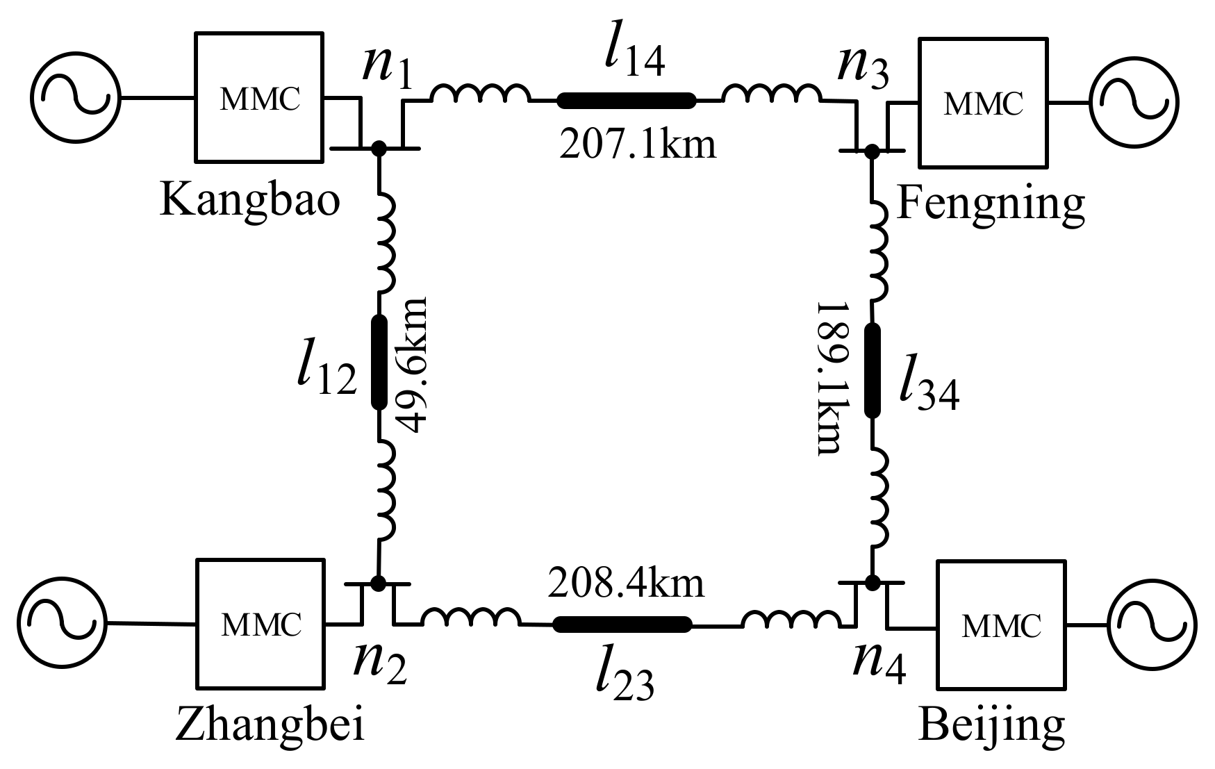
5.1. Description of the Test System

The test system adopted in this paper is the Zhangbei ±500 kV four-terminal bipolar DC grid in china. Its schematic diagram is illustrated in Figure 7. Kangbao, Zhangbei, Fengning and Beijing converter stations are abbreviated as s1-s4. Parameters of the Zhangbei DC grid are listed in Table 1. Generally, due to the delay of the communication system, the converters receive the blocking signal and then execute the blocking command with a delay of several cycles. Considering the factors such as short-term DC withstand voltage and thermal stress tolerance, the delay should generally not exceed 10 ms. This paper is suitable for estimating the fault characteristics prior to the blocking, but unfortunately the blocking of MMCs cannot be modeled. Therefore, an identical calculation step of 10 ms and time step of 50 us is set for the EMT simulation performed on PSCAD and the presented method performed on MATLAB.

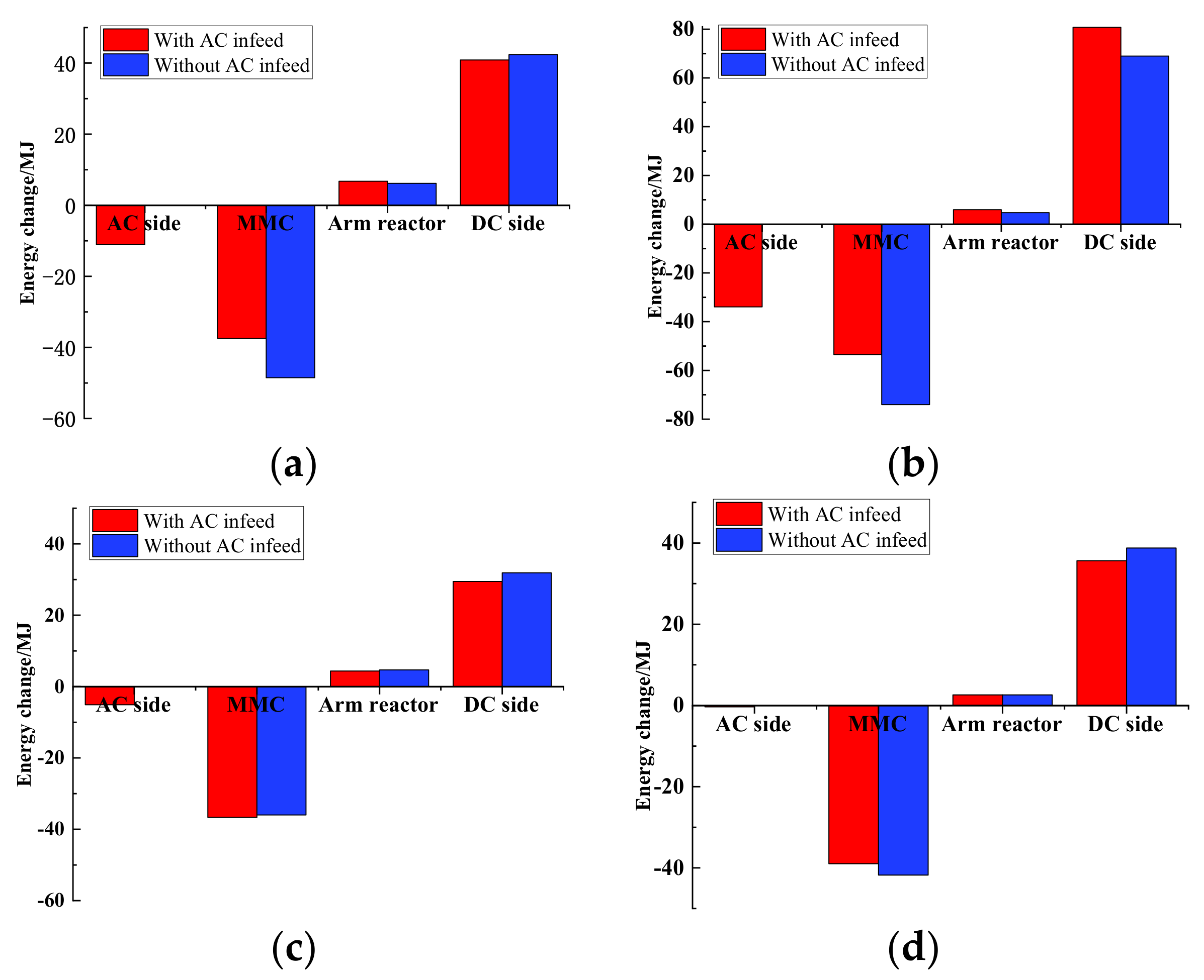
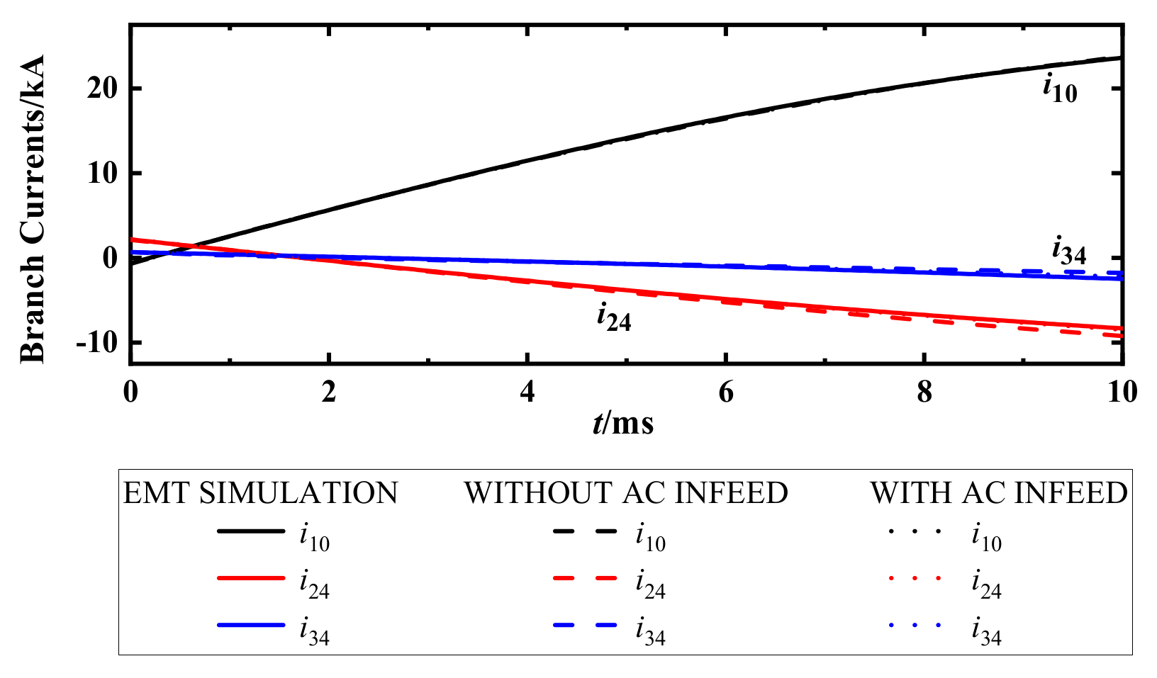
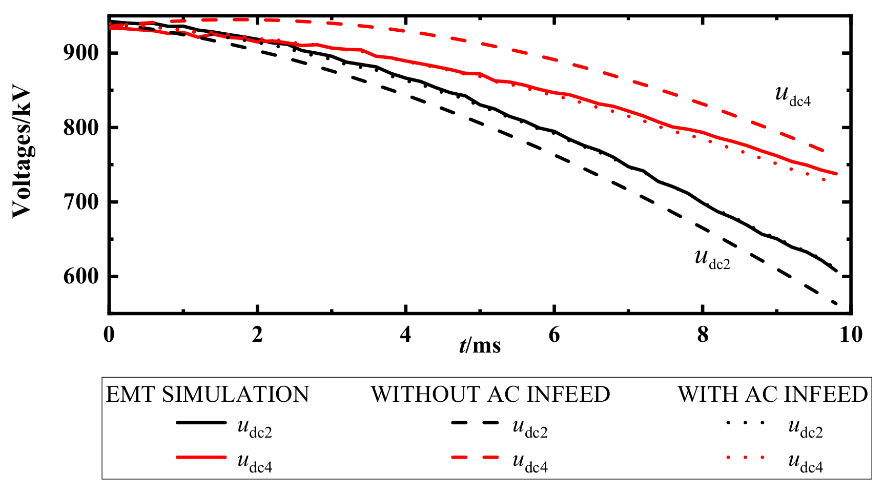
5.2. Influence of the AC Infeed

Taking into account the AC infeed during the fault, the energy is well balanced between the AC side and the DC side:
E dc = E ac + E L C O N V
where, Edc represents the energy storage of DC side including the energy in lines and reactors. Eac represents the energy input from the AC system, and ECONV represents the released energy of an MMC converter. EL is the released energy of the phase reactors. Edc and Eac can be calculated as follows:
E dc = t 0 t 0 + Δ t p dc d t E ac = t 0 t 0 + Δ t p ac d t
where, t0 is when the fault occurs. △t is the calculation time.
Since the equivalent resistance of the arm is usually small, the energy change of the resistance can be ignored. The energy storage components of the MMC mainly include the sub-module (SM) capacitors. The total stored energy of the SM capacitors and the inductors are respectively listed as follows.
E 1 2 j = a , b , c 2 C 0 N u p j 2 t 0 + Δ t u p j 2 t 0 + u l j 2 t 0 + Δ t u l j 2 t 0 C O N
E = L arm 2 j = a , b , c i p j 2 t 0 + Δ t i p j 2 t 0 + j = a , b , c i l j 2 t 0 + Δ t i l j 2 t 0 L + L d c 2 i d c 2 t 0 + Δ t d c 2 t 0 × 2
According to the analysis of power transfer among the AC side, DC side and MMC’s internal components, the influence of the AC active power on the fault currents and voltages could be studied. Based on Equations (23)–(26), the energy changes of the DC side, MMC internal components and AC side of each converter station within 10 ms after the fault occurs with and without AC infeed are shown in Figure 8.
It could be seen from Figure 8 that whether the AC infeed is taken into account or not, the energy of the SM capacitors changes the most. For sending end converter stations (such as s1 and s2), the energy released by the SM capacitors is reduced when there is AC infeed. For receiving end converter stations (such as s3 and s4), the energy released by the SM capacitors increases when the AC side absorbs energy from the DC system. As a dynamic energy balance between the AC side and the SMs is maintained in the whole process, the energy released to the DC side changes slightly.
For station s1 and s2, AC active power can make up part of the power required by the DC side, delaying the discharge rate of the sub-module capacitors. For station s3 and s4, there is a rise in the energy of the SMs capacitor for a short period of time without AC infeed. Due to the freewheeling effect of the smoothing reactor, the pre-fault current injecting into the converter will not be reversed immediately. When the AC active power is taken into the calculation, the DC current flowing into the converter station is absorbed by the AC system. When the DC current is reversed, the AC side and the DC side release energy together. Therefore, the total energy of AC system changes very small. And the DC voltage of the MMC drops slower than the response speed of the controller. In this case, the modulation ratio drops very fast, leading to a dynamic imbalance between the modulation ratio and the DC voltage. At this stage, MMC is in a state of undermodulation, which makes the average SM capacitor voltage rises passively and the energy of the capacitor increases. Therefore, accurately estimating the branch currents and node voltages needs considering the AC side power and MMC control.

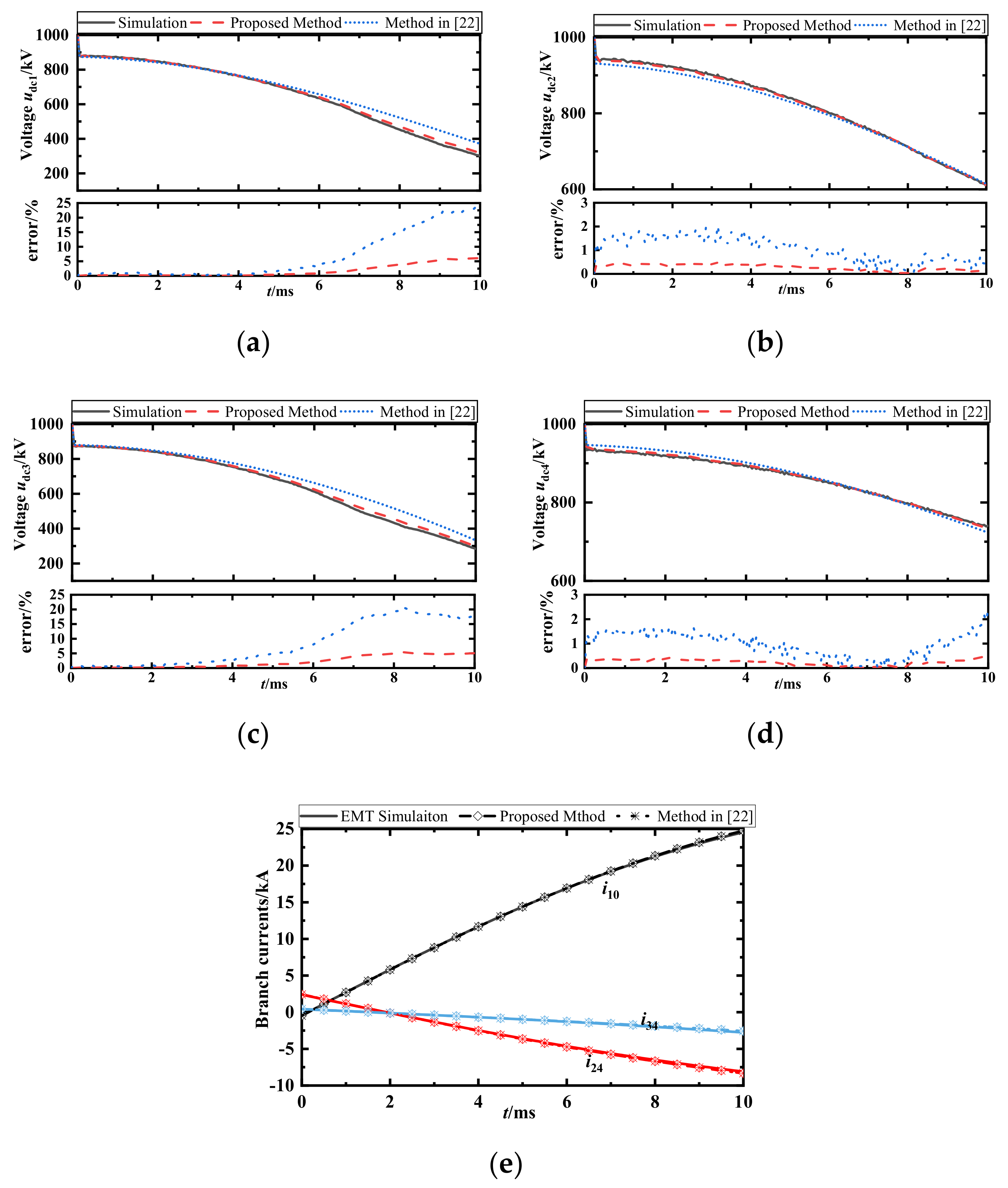
5.3. Accuracy Validation of the Proposed Method

To show the importance of the AC side power on estimating the branch currents and node voltages, here is a comparison of the results with and without AC infeed. It is assumed that the system has already been in steady-state. At t = 0 ms, a pole-to-pole fault occurs on the line side of s1 at line l12. Table 2 gives the initial values of branch currents and node voltages. Figure 9 and Figure 10 show the comparison between the current results and the voltage results obtained by numerical calculation and EMT simulation, respectively.
It could be seen from Figure 9 that the branch currents coincide with those computed by the EMT simulation. This is achieved by including the MMC control into the AC output voltage of MMC. The proposed method also shows good accuracy in the unfaulted branch currents i24 and i34 especially at 5–10 ms after the fault since the controller takes effect at this time.
From Figure 10, it could be seen that there are evident errors in estimating node voltages if AC infeed is not considered. For sending end converter station s2, the voltage udc2 decreases much faster than the proposed method. For receiving end converter station s4, the voltage udc4 firstly rises to some extent and then decreases. This is because the AC side releases the power required by the DC side for the sending end and plays the role of absorbing and releasing power flowing into the converter station for the receiving end. Since all MMC controllers are represented by variable controlled current sources, the proposed method shows sufficient accuracy in estimating the node voltages.

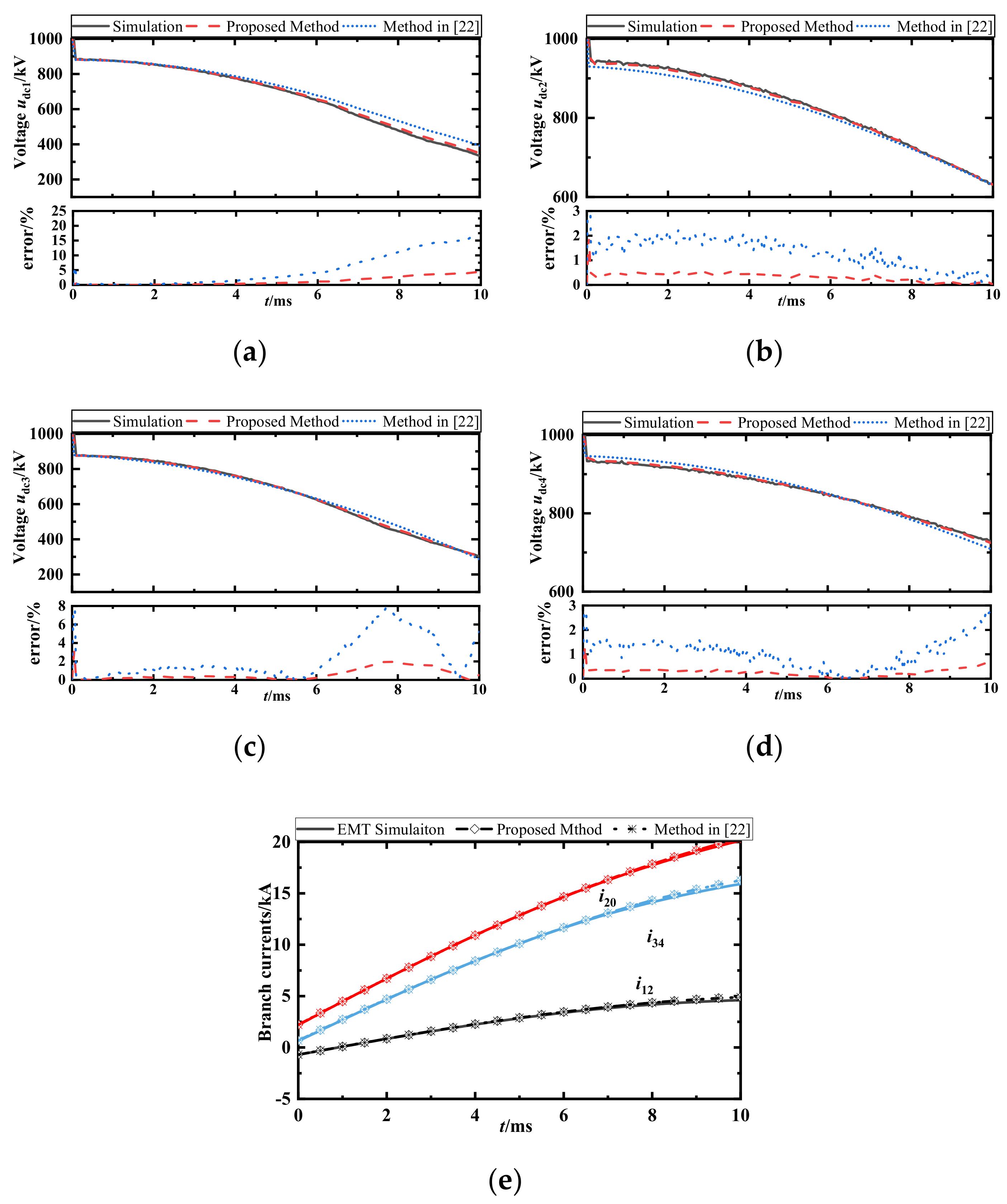
5.4. Accuracy Enhancement of the Presented Method

The methods proposed in [22,23] are endowed with greatly improved accuracy since the impacts of MMC control are involved. However, the equivalent DC current sources for converters in the active power control mode are assumed to be constant, leading to small bias in estimating the node voltages. Different from them, a variable current source is adopted in this paper to model the control dynamics of MMCs in active power and voltage control modes. The improved accuracy in estimating the node voltages will be expressed as follows.

5.4.1. Pole-to-Pole Fault Near Station s1 under Constant Active Power Control

It is assumed that the system has already been in steady-state. At t = 0 ms, a pole-to-pole fault occurs on the line side of s1 at line l12. The results obtained by the simulations, the proposed method and the methods in [22,23] are shown in Figure 11. The relative errors are also given in Figure 11. It could be seen that compared with the results obtained by the method in [22,23], the proposed method shows improved accuracy in estimating the node voltages. Especially, for stations s1 and s3 with large AC active power change during 5–10 ms after the fault, the proposed method shows tiny errors in estimating the node voltages. Since the control dynamics are taken into account, the errors in estimating the node voltages can be reduced to less than 5%. It could also be seen from Figure 11e that the proposed method and the method in [22,23] estimate the branch currents accurately in about the same extent.

5.4.2. Pole-to-Pole Fault Near Station s4 under Constant DC Voltage Control

It is assumed that the system has already been in steady-state. At t = 0 ms, a pole-to-pole fault occurs on the line side of s4 at line l24. The results and errors obtained by simulations, the proposed method and the methods in [22,23] are shown in Figure 12.
Similar conclusions could be drawn from Figure 12 that the proposed method shows greatly improved accuracy in estimating the node voltages especially 5–10 ms after the fault. The branch currents could be estimated accurately in both the proposed method and the method in [22,23].
In summary, it could be concluded from Section 5.3 and Section 5.4 that high accuracy shows in the branch currents and node voltages computed by the presented method and EMT simulation no matter where the fault occurs. Compared with the existing methods, the proposed method gives more accurate node voltages of the whole DC grid.

6. Conclusions

From the perspective of power balance, this paper proposes a highly accurate estimation method of the fault currents and fault voltages for the whole bipolar DC grid. The following conclusions could be drawn from the comparisons between the EMT simulation and numerical calculation.
(1) For the sending end converter, the active power on the AC side slows down the discharge rate of the sub-module capacitors. For the receiving end converter, the AC side plays the role of absorbing and releasing energy. Therefore, AC active power are supposed to be taken into account in the equivalent DC model of MMC.
(2) By modeling all MMC controls and AC active power as variable controlled current sources, compared with the existing literature, the accuracy for estimating the node voltages is greatly improved, especially for converters with large active power change during the fault. Besides, the relative errors in the node voltages are all reduced to less than 5%, which shows the sufficient accuracy of the proposed method.
(3) High accuracy is guaranteed by the propose method in estimating the branch currents and node voltages in the stage of capacitor discharging after the fault. Unfortunately, the converter blocking phase cannot be modelled with this method. How the proposed method could be used for dealing with the transient characteristics estimation during the freewheeling stage and steady state after the fault will be further discussed in the future work.

Author Contributions

Data curation, J.Z.; Formal analysis, H.C. and J.Y.; Investigation, J.Z.; Methodology, Z.Z.; Project administration, H.C.; Software, J.Y.; Supervision, J.Y.; Validation, Z.Z.; Visualization, J.Z. and Z.Z.; Writing—original draft, H.C. and J.Z.; Writing—review & editing, J.Y. and Z.Z. All authors have read and agreed to the published version of the manuscript.

Funding

This research received no external funding.

Institutional Review Board Statement

Not applicable.

Informed Consent Statement

Not applicable.

Data Availability Statement

Not applicable.

Conflicts of Interest

The authors declare no conflict of interest.

References

  1. Nami, A.; Liang, J.; Dijkhuizen, F.; Demetriades, G.D. Modular multilevel converters for HVDC applications: Review on converter cells and functionalities. IEEE Trans. Power Electron. 2015, 30, 18–36. [Google Scholar] [CrossRef]
  2. Zhao, B.; Song, Q.; Li, J.; Xu, X.; Liu, W. Comparative analysis of multilevel-high-frequency-link and multilevel-DC-link DC-DC transformers based on MMC and dual-active-bridge for MVDC application. IEEE Trans. Power Electron. 2018, 33, 2035–2049. [Google Scholar] [CrossRef]
  3. Tang, Y.; Chen, M.; Ran, L. A compact MMC submodule structure with reduced capacitor size using the stacked switched capacitor architecture. IEEE Trans. Power Electron. 2016, 31, 6920–6936. [Google Scholar]
  4. Xu, Z. Modular Multilevel Converter-Based High Voltage DC Power Transmission Systems, 2nd ed.; China Machine Press: Beijing, China, 2016; pp. 378–380. [Google Scholar]
  5. Bucher, M.K.; Wiget, R.; Andersson, G.; Frank, M.C. Multiterminal HVDC networks—What is the preferred topology? IEEE Trans. Power Del. 2014, 29, 406–413. [Google Scholar] [CrossRef]
  6. Liu, G.; Xu, F.; Xu, Z.; Zhang, Z.; Tang, G. Assembly HVDC breaker for HVDC grids with modular multilevel converters. IEEE Trans. Power Electron. 2017, 32, 931–941. [Google Scholar] [CrossRef]
  7. Mokhberdoran, A.; Hertem, D.V.; Silva, N.; Leite, H.; Carvalho, A. Multi-port hybrid HVDC circuit breaker. IEEE Trans. Ind. Electron. 2017, 65, 309–320. [Google Scholar] [CrossRef] [Green Version]
  8. Shukla, A.; Demetriades, G. A survey on hybrid circuit-breaker topolo-gies. IEEE Trans. Power Del. 2015, 30, 627–641. [Google Scholar] [CrossRef]
  9. Shi, J.; Tang, Y.; Chen, L. The application of active superconducting DC fault current limiter in hybrid AC/DC power supply systems. IEEE Trans. Appl. Supercond. 2008, 18, 672–675. [Google Scholar]
  10. Li, C.; Gole, A.M.; Zhao, C. A fast dc fault detection method using dc reactor voltages in HVDC grids. IEEE Trans. Power Del. 2018, 33, 2254–2264. [Google Scholar] [CrossRef]
  11. Bucher, M.K.; Franck, C.M. Contribution of fault current sources in multi-terminal HVDC cable networks. IEEE Trans. Power Del. 2013, 28, 1796–1803. [Google Scholar] [CrossRef] [Green Version]
  12. Han, X.; Sima, W.; Yang, M.; Li, L.; Yuan, T.; Si, Y. Transient characteristics under ground and short-circuit faults in a ±500 kV MMC-based HVDC system with hybrid dc circuit breakers. IEEE Trans. Power Del. 2018, 33, 1378–1387. [Google Scholar] [CrossRef]
  13. Zhang, Z.; Xu, Z. Short-circuit current calculation and performance requirement of HVDC breakers for MMC-MTDC systems. IEEE Trans. Electr. Electron. Eng. 2016, 11, 168–177. [Google Scholar] [CrossRef]
  14. Tünnerhoff, P.; Ruffing, P.; Schnettler, A. Comprehensive fault type discrimination concept for bipolar full-bridge-based MMC HVDC sys-tems with dedicated metallic return. IEEE Trans. Power Del. 2018, 33, 330–339. [Google Scholar] [CrossRef]
  15. Li, C.; Zhao, C.; Xu, J.; Ji, Y.; Zhang, F. An A pole-to-pole short circuit fault current calculation method for dc grids. IEEE Trans. Power Syst. 2017, 32, 4943–4953. [Google Scholar] [CrossRef]
  16. Liu, S.; Xu, Z.; Hua, W.; Tang, G.; Xue, Y. Electromechanical transient modeling of modular multilevel converter based multi-terminal HVDC systems. IEEE Trans. Power Syst. 2014, 29, 72–83. [Google Scholar] [CrossRef]
  17. Li, Y.; Tang, G.; Ge, J.; He, Z.; Pang, H.; Yang, J.; Wu, Y. Modeling and damping control of modular multilevel converter based dc grid. IEEE Trans. Power Syst. 2018, 33, 723–735. [Google Scholar] [CrossRef]
  18. Li, R.; Xu, L.; Holliday, D.; Page, F.; Finney, S.J.; Williams, B.W. Continuous operation of radial multiterminal HVDC systems under dc fault. IEEE Trans. Power Del. 2016, 31, 351–361. [Google Scholar] [CrossRef] [Green Version]
  19. Eriksson, R. Current sharing in multi-terminal dc grids—The analytical approach. IEEE Trans. Power Syst. 2018, 33, 6278–6288. [Google Scholar] [CrossRef]
  20. Tang, L.; Dong, X. An approximate method for the calculation of transmission line fault current in MMC-HVDC grid. Proc. CSEE 2019, 39, 178–186. [Google Scholar]
  21. Duan, G.; Wang, Y.; Yin, T.; Yin, S.; Li, G.; Sun, S. DC short circuit current calculation for modular multilevel converter. Power Syst. Technol. 2018, 42, 2145–2152. [Google Scholar]
  22. Langwasser, M.; Carne, G.D.; Liserre, M.; Biskoping, M. Fault current estimation in multi-terminal HVdc grids considering MMC control. IEEE Trans. Power Syst. 2019, 34, 2179–2189. [Google Scholar] [CrossRef]
  23. Langwasser, M.; de Carne, G.; Biskoping, M.L.M. Improved fault current calculation method for pole-to-pole faults in MMC Multi-Terminal HVDC Grids Considering Control Dynamics. In Proceedings of the 2018 IEEE Energy Conversion Congress and Exposition (ECCE), Portland, OR, USA, 23–27 September 2018; pp. 5529–5535. [Google Scholar]
  24. Trinh, N.; Zeller, M.; Wuerflinger, K.; Erlich, I. Generic Model of MMC-VSC-HVDC for interaction study with AC power system. IEEE Trans. Power Syst. 2016, 31, 27–34. [Google Scholar] [CrossRef]
  25. Wang, J.; Bai, H.M.Z. A submodule fault ride-through strategy for modular multilevel converters with nearest level modulation. IEEE Trans. Power Electron. 2018, 33, 1597–1608. [Google Scholar] [CrossRef]
  26. Shen, K.; Wang, S.; Zhao, D.; Zhao, G. A discrete-time low-frequency-ratio nearest level modulation strategy for modular multilevel converters with small number of power modules. IEEE Access 2019, 7, 25792–25803. [Google Scholar] [CrossRef]
  27. Liang, Y.; Liu, J.; Zhang, T.; Yang, Q. Arm current control strategy for MMC-HVDC under unbalanced conditions. IEEE Trans. Power Del. 2017, 32, 125–134. [Google Scholar] [CrossRef]
  28. Li, S.; Wang, X.; Yao, Z.; Li, T.; Peng, Z. Circulating current suppressing strategy for MMC-HVDC based on nonideal proportional resonant controllers under unbalanced grid conditions. IEEE Trans. Power Electron. 2015, 30, 387–397. [Google Scholar] [CrossRef]
Figure 1. Basic structure of MMC.
Applsci 11 02882 g001
Figure 2. Equivalent model of MMC.
Applsci 11 02882 g002
Figure 3. Discrete adjoint model of series-connected resistance-inductor branch: (a) original circuit; (b) discrete adjoint model.
Applsci 11 02882 g003
Figure 4. Discrete adjoint model of capacitor branch: (a) original circuit; (b) discrete adjoint model.
Applsci 11 02882 g004
Figure 5. Discrete adjoint model of MMC.
Applsci 11 02882 g005
Figure 6. Simplified model between any two adjacent nodes.
Applsci 11 02882 g006
Figure 7. Schematic Diagram of the Zhangbei ±500 kV bipolar DC grid.
Applsci 11 02882 g007
Figure 8. Energy changes between the AC side and DC side: (a) station s1; (b) station s2; (c) station s3; (d) station s4.
Applsci 11 02882 g008
Figure 9. Branch currents obtained by EMT simulation and numerical calculation.
Applsci 11 02882 g009
Figure 10. DC voltages at the terminal of s2 and s4 obtained by EMT simulation and numerical calculation.
Applsci 11 02882 g010
Figure 11. Branch currents and node voltages obtained by EMT simulation, the proposed method and the method in [22]: (a) udc1 of station s1; (b) udc2 of station s2; (c) udc3 of station s3; (d) udc4 of station s4; (e) branch currents.
Applsci 11 02882 g011
Figure 12. Branch currents and node voltages obtained by EMT simulation, the proposed method and the method in [22]: (a) udc1 of station s1; (b) udc2 of station s2; (c) udc3 of station s3; (d) udc4 of station s4; (e) branch currents.
Applsci 11 02882 g012
Table 1. Main Circuit Parameters of the Test System.
ItemsValues
Converter Stations
Rated AC voltage (kV)230 (s1,s3)/525 (s2,s4)
Transformer impedance(p.u.)0.0176 (s1,s3)/0.0088 (s2,s4)
Smoothing reactor(mH)300
Rated capacity(MW)1500 (s1,s3)/3000 (s2,s4)
Rated DC voltage±500 kV
Arm inductor(mH)40 (s1,s3)/75 (s2,s4)
SM capacitor(uF)10000 (s1,s3)/15000 (s2,s4)
Number of SMs per arm218
DC transmission lines
Resistance per unit length0.009735 Ω/km
Inductance per unit length0.0176 mH/km
Capacitance per unit length0.001367 μF/ km
Control mode
s1Q = 0 MVar, P = −1500 MW
s2Q = 0 MVar, P = −3000 MW
s3Q = 0 MVar, P = 1500 MW
s4Q = 0 MVar, Udc = ±500 kV
Table 2. Steady-state Values of the Pole-to-pole Voltage and Branch Current.
Itemi10/kAi20/kAi13/kAI24/kAI34/kA
Value−0.6940.6941.4342.2100.682
Itemudc1/kVudc2/kVudc3/kVudc4/kV/
Value1008.721009.861002.391000.00/
Publisher’s Note: MDPI stays neutral with regard to jurisdictional claims in published maps and institutional affiliations.

