Abstract
Recently, private security services have become increasingly needed by the public. The proposed scheme involves blockchain technology with a smart contract. When a private security company signs a contract with a client, they install an Internet of Things (IoTs) device in the client’s house and connect it with the IoT main controller; then, the IoT main controller connects to the security control center (SCC). Once there is an event triggered (e.g., a break-in or fire incident) by the IoTs device, the controller sends a message to the SCC. The SCC allocates a security guard (SG) to the incident scene immediately. After the task is accomplished, the SG sends a message to the SCC. All of these record the messages and events chained in the blockchain center. The proposed scheme makes security event records have the following characteristics: authenticated, traceable, and integral. The proposed scheme is proved by a security analysis with mutual authentication, traceability, integrity, and non-repudiation. The known attacks (e.g., man-in-the-middle attack, replay attack, forgery attack) are avoided by message encryption and a signing mechanism. Threat models in the communication phase can also be avoided. Finally, computation cost, communication performance, and comparison with related works are also discussed to prove its applicability. We also provide an arbitration mechanism, so that the proposed scheme can reduce disputes between private security companies and the client.
1. Introduction
1.1. Background
In recent years, the economy has become more and more prosperous, but the security of the city has not improved along with economic growth. To strengthen the security of the city, except for the police placed by the government in the city, the general company or the community will sign a contract with a private security company, and that company provides the security service to ensure the property of the client. Nalla [1] wrote that “There has been a steady increase in security guard employment in the United States in recent decades. Data estimates for 2010 suggest that there are over 10,000 security companies in the United States, employing 1,046,760 guards.” The above description indicates that the demand to hire private security services is increasing and the social needs of the security industry have become very important.
Furthermore, the Federal Bureau of Investigation (FBI) in the United States analyzes offense statistics every year [2]. We sorted out the annual statistics from 2015 to 2019 regarding cases of burglary and larceny-theft in buildings. Table 1 shows the number of the two types of cases and the average US dollar value of the property loss. Except for the United States, the burglary record in England and Wales has come to 417,416 cases [3]. Therefore, private security services are important to prevent the occurrence of criminals. When crime continues to exist, people need the service to avoid it.

Table 1.
FBI offense statistics from 2015 to 2019 [2].
There are several types of services of private security companies: community security, patrol security, bodyguards, armored cars, etc. In this research, we focus on community security. The operation of community security comprises several cars with security guards patrol in a specific area; if a client’s house or company sends an alarm to the security control center, the control center needs to notify the security guards and solve the problem to protect the property of the client.
Most security companies include security systems with their services, such as video surveillance cameras, access control keys, and virtual fencing systems [4]. Nowadays, many Internet of Things (IoTs)-related products have been developed, e.g., door/window sensors, smoke detectors, motion sensors, and alarm sirens. Those devices can also be integrated into the security system which makes the system automated. Although the ability to automatically alert has been achieved, there are still some problems. Firstly, the security of the Internet of Things is constantly being challenged [5,6]. Secondly, the security company is unable to keep trackable records; it is insufficient to clarify the responsibility between the security company and the client. However, if it needs real-time processing, records can be verified and traceable.
Blockchain is a technology that can solve issues. Blockchain technology is widely applied to the cryptocurrency Bitcoin. Bitcoin was developed and deployed by Nakamoto in 2008 [7]; it is a digital virtual currency that is secured by cryptography [8]. The notion of blockchain is decentralized networks, and every data chained in the network is irreversible. Blockchains are also authentic, consistent, able to provide consensus, and traceable. Because of the characters and advantages, blockchain technology has been affected and applied in various fields in recent years; for example, in healthcare [9,10,11], payment [12,13,14], digital content [15,16,17], etc. For all the benefits mentioned above, blockchain technology is very suitable to be involved in security systems. There are at least three types of blockchains: public blockchains, private blockchains, and hybrid blockchains. In our scheme, private blockchains are more suitable for protecting customer privacy, and it is maintainable by the security service provider. Those security events are stored in an immutable ledger, and the ledger will be mainly stored with the security company, official agency, and client, to ensure that the information will not be arbitrarily altered.
To sum up, our research aims to accomplish the following goals: an automated alarm system that communicates with the security control center to propose an authentication protocol that supports real-time event status report/record, data traceability, data integrity, data non-repudiation, and proposes an arbitration mechanism when the dispute occurs.
1.2. Related Works
The related works are surveyed and shown in Table 2. In this table, it can be seen that some of the related literature are compared with their characteristics. There are lots of security services applied within a smart home, a city, campuses, and industries; the most important element of these smart services is using large amounts of IoT devices to achieve automated security services. Some of these authors also used blockchain to ensure the architecture of communication between IoTs is more secure.
Table 2.
The related works survey.
Smith et al. [18] introduced a security service with central alarm stations and dispatch centers. The monitoring system has various sensors that cooperate with the central station, (the central station is known as the security control center); if there an alarm is triggered and transmitted to the monitoring system, the center will dispatch an official to resolve the problem. These information automated security services can ensure the safety of the protected person or property, but if there is no information security technology that is involved and analyzed, the service may be subject to cyber-attacks.
Liu et al. [19] proposed a blockchain-based access control system with IoT in 2020. The system contains three types of smart contracts, which are Device Contract (DC), Policy Contract (PC), and Access Contract (AC). The author used a decentralized management framework, but they did not prove the security analysis of the scheme. Lin et al. [20] proposed a blockchain-based access control system in 2018. The system was designed to be used in industry 4.0, and the information security technology is also included in the proposed scheme; however, there is no security control center dispatch mechanism to keep monitoring and to dispatch professionals to handle the problem.
Other applications, such as smart homes and smart campuses, also implement blockchain and IoT technology. Mbarek et al. [21] proposed a blockchain-based access control to control smart home devices, but the main disadvantage of their research is the lack of information security analyses. Alkhammash et al. [22] applied blockchain technology in smart campuses; they proposed a new smart campus framework with some layers, such as a physical layer, communication layer, platform layer, data layer, business layer, and application layer, but the research lacked a traceable mechanism and security analysis.
There is some literature involved in the research of smart homes and information security analyses. Lyu et al. [23] were involved in information security with an IFTTT (if this then that) gateway in the smart home; the proposed method implemented authentication and key agreement schemes when the user accessed the gateway remotely. Furthermore, Fakroon et al. [24] proposed remote anonymous authentication for smart homes. These studies lack record traceability and integrity.
To summarize the shortcomings of the current research, there is no literature proposing complete security services by a third-party; for example, private security guards, and community security companies. Properly storing the content of the incident is also important for trust between the services provider and client, so it is also important to store complete records of the event processing to achieve traceability, integrity, non-repudiation, etc. Therefore, we propose smart contracts that enable chaining the event’s record on the blockchain center.
The remaining sections of this paper are organized as follows: Section 2 introduces the techniques that are used in our proposed scheme. Section 3 presents our proposed scheme. The security analysis and comparison discussion are given in Section 4 and Section 5, respectively. Finally, Section 6 concludes this paper.
2. Preliminary
2.1. Smart Contract and Blockchain
In 2014, Buterin implemented the first blockchain-based smart contracts technologies of Ethereum [25]. As an event occurs, a smart contract is able to be executed by the pre-designed program automatically; every smart contract that is chained to the blockchain also inherits the characteristics of the blockchain. Therefore, we applied private blockchains with the Ethereum framework. Commonly, there are many types of consensus algorithms in blockchain technologies, e.g., Proof-of-Work (PoW), Proof-of-Stake (PoS), and Proof-of-Authority (PoA). Most private enterprise blockchain applications use a PoA consensus. F. Þ. Hjálmarsson et al. proposed a blockchain-based e-voting system with PoA in 2018 [26]. Neo also proposed an enterprise blockchain that implements supply chain anti-counterfeiting and traceability [27]; the proposed scheme also applied the PoA-based consensus in the blockchain. The PoA consensus algorithm uses fewer computing resources to quickly validate and upload the block to the blockchain. According to the advantages of PoA, our proposed scheme is implemented with PoA. By applying PoA in our private blockchain, only authorized accounts can verify transactions and blocks; therefore the information of the client is kept confidential.
2.2. ECDSA
Vanstone [28] proposed the Elliptic Curve Digital Signature Algorithm (ECDSA) in 1992, which is a derived type of the Digital Signature Algorithm (DSA) that uses Elliptic Curve Cryptography (ECC). ECC is a type of public-key cryptography based on the algebraic structure of elliptic curves over finite fields. The characteristics of ECC make the ECDSA require a significantly smaller key size with the same level of security which offers faster computations and less storage space.
Johnson et al. [29] introduced the ECDSA in detail, including its acceptance in any global standards. ECDSA is accepted in the following standards:
- (1)
- ISO 14888-3: International Standards Organization standard in 1998.
- (2)
- ANSI X9.62: American National Standards Institute standard in 1999.
- (3)
- IEEE 1363-2000: Institute of Electrical and Electronics Engineers standard in 2000.
- (4)
- FIPS 186-4: Federal Information Processing standard in 2013.
- (5)
- ANSI X9.142-2020: American National Standards Institute standard in 2020.
Next, we briefly describe the three phases of ECDSA key generation for verification:
- (1)
- Key generation phase: We assume that any participant must apply to our blockchain center for public and private keys, and the key generation with the ECDSA is as follows: , where is the participant ID, is the public key, is the private key, and is a generating point based on the elliptic curve. The public key and private key are sent to the participant and stored. is also stored in the blockchain center.
- (2)
- Signature phase: There is a message that needs to be sent by participant X to Y. X choose a random number k between 1 and n − 1, and calculates a point on the curve as follows . Then, it calculates . Next, X signs a message M as follows: , sends to Y.
- (3)
- Verification phase: When Y receives , it then calculates the parameters as follows: . Then, it verifies to determine if the signature is valid.
In general, some key parameters need to be defined: in our proposed scheme, the length of bits and Secure Hash Algorithm (SHA), according to the NIST’s minimum security-strength requirement [30], set the length of n with 224 bits and SHA-512/224 for digital signature generation.
2.3. BAN Logic
Burrows et al. [31] proposed BAN logic, a defining logic for the analysis of security protocols in 1990. BAN logic is a logic of beliefs, and the purpose of BAN logic is to analyze authentication protocols by deriving the beliefs [32]. Therefore, BAN logic can be used for validating the mutual authentication with the communication protocols.
2.4. Threat Model
The threat model involves the understanding of latent threats to the system; it is an important security analysis that needs to be done to determine the method of defense. When the security services system is implemented in the security company, various threats may be encountered. The threats are as follows:
- (1)
- The integrity of data: The data sent by the sender must not be modified or destroyed by other parties so as to guarantee privacy and security [33]. When the receiver receives the message, they are able to verify the completeness of the data to guarantee that the data will not be missed.
- (2)
- Untraceable record: Every record that is generated from a security services company is saved in the database; the record can be freely modified by the service provider, and customers that apply the security service are unable to trace their records correctly. An automated and traceable record included at every stage of the case processing is important to various applications for making evidence in the arbitration phase (for example, medical, criminal, smart home, etc.) [34,35,36].
- (3)
- Message repudiation: A digital signature can ensure the non-repudiation of the message [37]. Every message that sends from the sender should be signed with the sender’s private key; it makes the receiver able to prove that the message is definitely from the sender.
- (4)
- Third-party arbitration: The responsibility clarification is important when there is a doubt that occurs. In the traditional security service, the client only can doubt the security company, and the company is able to falsify the record to protect the company’s reputation. So the third-party fair arbitration is important for clarification [38].
- (5)
- Cyber-attacks: There are some cyber-attacks by attackers that must be considered; for example, a man-in-the-middle attack [39], replay attack [40], forgery attack [41], etc.
- (6)
- Unstable communication: There is some internet communication between IoT devices, such as the IoT main controller, clients, and security company. The unstable communication will cause data loss and the message will not be completed. Therefore, the stabilization of communication must be taken seriously [42].
- (7)
- Side-channel attack: This is a physical security attack. There are various kinds of side-channel attacks, such as Simple Power Analysis (SPA) and Differential Power Analysis (DPA) [43]. This type of attack monitors the power consumption of the electronic device to extract important data like secret keys [44]. Daniel et al. demonstrated an ECDSA key extraction from mobile devices with a side-channel attack [45].
3. The Proposed Scheme
The proposed system consists of the following six parties: the client, the IoT main controller of the client’s house, the security control center, the security guard, the blockchain center, and the official agency. The system framework is shown in Figure 1.
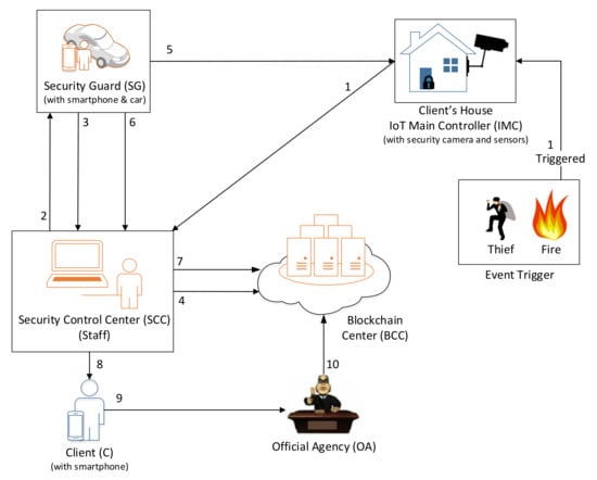
Figure 1.
System framework of the proposed scheme.
3.1. System Architecture
- Client (C): The customer needs a security service from the security company. He/she carries a smartphone with the security company’s application that enables them to get the notification when an event happens at his/her house.
- IoT main controller (IMC): A controller that is installed in a client’s house, and connects to every Internet of Things (IoT) device in the house, e.g., camera, alarm sensors, magnetic contact, switched, motion detection devices, and fire detection devices. All security events are controlled by the IoT main controller. Each sensor can be triggered by an event that triggers the security problem with the client’s house; for example, a thief breaking into the house, or a fire incident.
- Security control center (SCC): This is the security company’s control center that can monitor the client’s home security situation. If there is an event triggered by the client’s house, the control center’s staff needs to notify a security guard to take action and go to the client’s house to solve the problem.
- Security guard (SG): He/she drives a car and carries a smartphone. He/she needs to take action when they receive the task/notification from the SCC to solve the security problem in the first scene.
- Blockchain center (BCC): This is the blockchain that records the event. When an event from the client’s house is triggered, the BCC creates a record with an event ID, and sends an active notification to the SCC; every message reply to the event needs to be chained with the event ID.
- Official agency (OA): This is the third-party official agency. The client can ask to prove the contract and event from the BCC. The official agency has the right to prove that is there any problem when executing the contract from the security company.
All staff in the security company (including security control center staff, and the security guard) needs to register an account from the BCC to get a unique ID. When the client needs a security service from the security company, after the contract is signed, the client, the client’s house with the IoT main controller, and the IoT sensors that are inside the house also need to register to the BCC to get a unique ID, a public key, and a private key pair. Figure 1 presents the scenarios which are triggered by an event by some IoT devices (IoT) of the client’s house.
- Step 1.
- A thief breaks into the client’s house or a fire incident happens. The client’s house security system (with sensors) is triggered to the IMC, and the IMC notifies the SCC with a new event ID.
- Step 2.
- The SCC’s staff will connect and check the recorded video from the digital video recorder (DVR) before and after the occurrence event time manually. Every client’s house needs to install a digital video recorder (DVR) and connect it with multiple cameras to capture the critical area. Those devices are classified as IoT devices. If there are no abnormal movements or objects (e.g., human break-in, or fire) in the video, then that means it is a false alarm. The SCC’s staff checks if it is a false alarm or not and confirms it. Then, SCC searches for available SGs that are nearby the event client’s house. If there is an event at the client’s house, a notification will be sent to the specific SG.
- Step 3.
- If SG accepts the task, then the SG sends a confirmation message to SCC.
- Step 4.
- SCC generates and sends the confirmation message to BCC and chains the confirmation record in the BCC.
- Step 5.
- The SG goes to the incident scene and solves the security event.
- Step 6.
- After the event is solved, the security guard reports the detailed records and sends the report to the SCC.
- Step 7.
- SCC sends the record to BCC and chains the report to BCC.
- Step 8.
- The client receives the latest status notification from the SCC.
- Step 9.
- If the client does not satisfy the service of the security company, the client can propose an arbitration request to the official agency (arbiter).
- Step 10.
- Since the processing details (included the event timestamp and signature) are chained in the record, the OA can retrieve and verify the event record from the BCC.
3.2. Notation
The following is an explanation of these symbols.
| X’s identity | |
| X’s password | |
| Event ID that generates automatically while an event is triggered. The ID will be named in the format: (five digits of the postcode) + (five digits of the IMC ID) + (four digits of sequence value) | |
| The ith token issued by the BCC, which is used to prove whether the identity is legal | |
| The public key of party X, which is issued by the BCC | |
| The private key of party X, which is issued by the BCC | |
| The ith signature of X | |
| The ith ciphertext of X | |
| The ith hash value of X | |
| The ith timestamp that sender sends a message to the receiver | |
| The i + 1th timestamp that the receiver received a message from the sender | |
| The sequential number i from the sender increased to i + 1 in the next message | |
| The ith message of any party event information | |
| The message of any party that accessed SCC’s request message | |
| Encrypt/decrypt message M with a public key or private key of party X | |
| The hash value of a message M is calculated by a one-way hash function | |
| Determine if A is equal to B or not | |
| The threshold that checks the validity of the send and receives a timestamp |
3.3. Initialization Phase
All parties need to register with the SCC, and the public and private keys of all parties will be generated through the blockchain center; a public key and private key will be issued to parties. Figure 2 and Figure 3 are the smart contract structure of our scheme. The enumeration of the IoT type is shown in Figure 2, e.g., alarm, camera, fire detector, motion detector. The information structure of the security control center’s staff, security guard, client, and the IoT device information inside the client’s house are shown in Figure 3; all parties need to register their information with those defined data fields. The staff (including the control center’s staff, security guard) needs to login into the security control application when starting to work and log out when off-duty; those actions will connect to BCC and set the “OnDuty” variable to true or false.
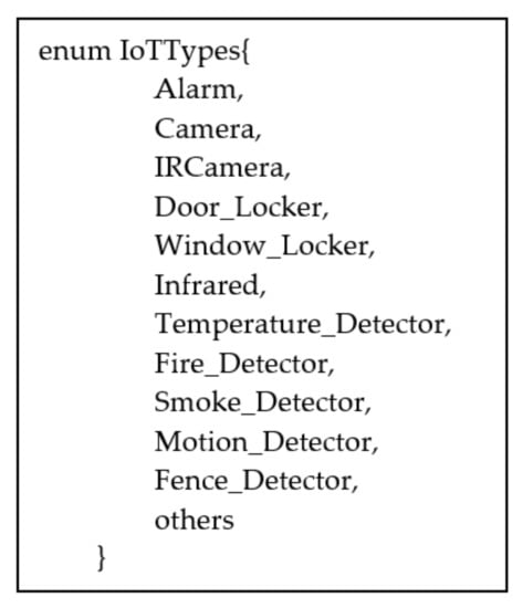
Figure 2.
The enumeration of IoT types.
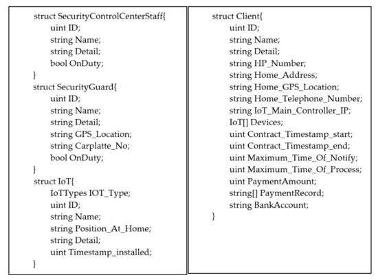
Figure 3.
Smart contract initialization.
3.4. Communication Phase
The SCC keeps a connection with the IoT main controller in the CH. When the connection is lost, the SCC will automatically send a notification to SG to solve the communication problem.
The scenario of the communication phase is shown in Figure 4. The situation of a loss of connection from the SCC to the client’s house, or if the IoT devices do not work, is detailed in the following steps:
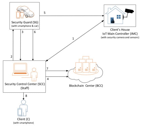
Figure 4.
The mechanism in the communication phase.
- Step 1.
- The SCC keeps communicating for the connection of the IMC in the client’s house every minute (depending on the contract). If the IoT devices or the controller of the client’s house does not respond, it means that the security mechanism is not working. SCC will trigger a lost connection event and record it.
- Step 2.
- The SCC staff check if it is a false alarm or not and confirm it. After confirmation, the SCC will search for available SGs who are nearby the client’s house location automatically. The event is authenticated by the SCC, and a notification will be sent to the specific SG who is near the house.
- Step 3.
- The SG confirms and accepts the task, and sends a confirmation message to the SCC.
- Step 4.
- The SCC sends the event confirmation to the BCC and chains the confirmation record in the BCC.
- Step 5.
- The SG will go to the incident scene and solve the communication problem.
- Step 6.
- After the problem is solved, the security guard will report the problem with details and send the content to the SCC.
- Step 7.
- The SCC sends the record to the BCC and chains the report in the BCC.
- Step 8.
- The client gets the latest status notification from the SCC.
3.5. Authentication Phase
In this phase, access parties (AP) need to be authenticated by the SCC. The AP means any party who wants to access the information of the SCC, for example, the client (C), the IoT main controller (IMC), and security guard (SG). After the verification, the party will get a token and the AP will use the token to access the information of the SCC. Figure 5 is the flowchart of the authentication phase.
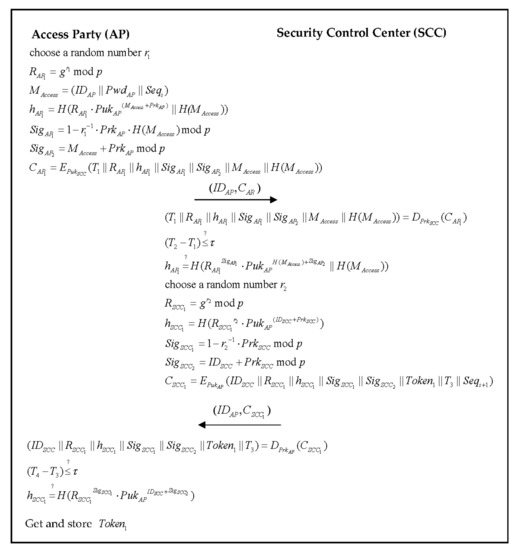
Figure 5.
The flowchart of the authentication phase.
Step 1. The AP selects a random number , and computes the following parameter:
AP computes the access message:
AP uses the hash function to compute the parameter :
and uses its private key and to compute the signatures as follows:
After that, AP uses the SCC’s public key to encrypt the message into a ciphertext :
Then, AP sends the to SCC.
Step 2. Once the SCC receives the AP’s ID and cipher message at , SCC uses the private key to decrypt the message:
Then, SCC checks the validity of the timestamp:
If the timestamp interval is valid, then SCC needs to verify AP’s hash parameter:
If Equation (9) holds, the SCC selects a random number , computes the following parameters:
SCC uses the hash function to compute the parameter :
SCC uses its private key and to compute the signatures as follows:
SCC generates , then SCC uses the AP’s public key to encrypt the message into cipher message :
Then, SCC sends the cipher message to AP.
Step 3. The AP receives the SCC’s and cipher message at , AP uses its private key to decrypt the messages:
Then, AP checks the validity of the timestamp:
If the timestamp interval is valid, then AP needs to verify SCC’s hash parameter:
If it is valid, AP gets the that can access the information of SCC in other phases.
In the authentication phase, when any parties need to access the information of SCC, they must send their identity authentication to the SCC before communication.
3.6. Event–Trigger Phase
In this phase, any IoT devices can send trigger signals to the IMC in the client’s house. For example, the client installs some IoT devices (sensors) on doors and windows; when a thief enters the house silently and triggers the sensors, the sensors will send an event signal to the IMC. The event initialization structure and scenarios are presented in Figure 6 and Figure 7, respectively.
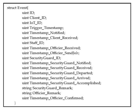
Figure 6.
Event initialization structure.
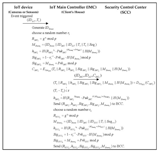
Figure 7.
The flowchart of the event-trigger phase.
Step 1. The IoT device sends a trigger signal with and the triggering time to the IMC.
Step 2. The IMC generates a unique event , to bind the event to record and trace the event status.
Then, the IMC selects a random number , and computes the following parameter:
The triggered IoT’s ID and IMC’s ID is written to the event message with a timestamp :
The IMC uses the hash function to compute the parameter :
The IMC uses its private key and to compute the signatures as follows:
After that, IMC uses the SCC’s public key to encrypt the message into a ciphertext :
Then, IMC sends to SCC.
Step 3. The SCC receives the IMC’s ID, IoT’s ID and cipher message at , SCC uses its private key to decrypt the message:
Then, SCC checks the validity of the timestamp:
If the timestamp interval is valid, then SCC needs to verify IMC’s hash parameter:
If Equation (26) holds, SCC will check the situation of the client’s house via cameras and sensors; if there is an available incident in the client’s house, the next step will be to search for a nearby SG and construct the connection to send the event message to the selected SG.
In the meanwhile, SCC sends and chains to BCC.
Step 4. Then, SCC selects a random number , and computes the following parameter:
The event’s ID, IMC’s ID, and SCC’s staff ID are written to the event message with a timestamp :
SCC uses the hash function to compute the parameter :
SCC uses its private key and to compute the signatures as follows:
Then, SCC sends and chains to BCC.
3.7. Task Allocating Phase
After receiving the event trigger message, the SCC’s staff will search for the nearest SG to the client’s house. Then, a task will be allocated to the selected SG by the SCC’s staff. Once the SG receives a task from the SCC’s staff, the SG will need to reply to the SCC’s staff that the job was accepted or rejected. If the job is accepted, the SG should go to the client’s house rapidly and solve the incident scene immediately. The SG also needs to report to the SCC’s staff in the task accomplished phase. The flowchart of the allocating task phase is illustrated in Figure 8.
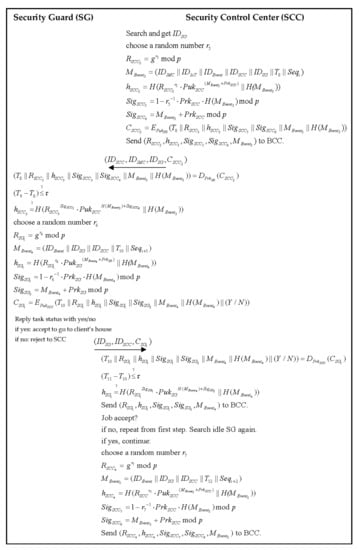
Figure 8.
The flowchart of the allocating task phase.
Step 1. The SCC searches for an idle SG automatically by the nearest distance to the client’s house and the SG gets allocated
Step 2. The SCC selects a random number , and computes the following parameter:
The allocated will be appended to the event message with a timestamp :
The SCC uses the hash function to compute the parameter :
The SCC uses its private key and to compute the signatures as follows:
Then, the SCC uses the SG’s public key to encrypt the message into a ciphertext :
Then, the SCC sends and chains to the BCC.
Meanwhile, the SCC sends the cipher message to the allocated SG.
Step 3. Once the SG receives the SCC’s ID, the IMC’s ID, the SG’s ID, and cipher message at , the SG uses the private key to decrypt the message:
Then, the SG checks the validity of the timestamp:
If the timestamp interval is valid, then the SG needs to verify the SCC’s hash parameter:
If Equation (40) holds, then the SG needs to reply to the SCC that they are accepting the task. If the SG does not accept the task, then they reply no, and otherwise reply yes. The SG selects a random number , and computes the following parameter:
A timestamp is appended to the event message:
SG uses the hash function to compute the parameter :
SG uses the private key and to compute the signatures as follows:
Then the SG uses the SCC’s public key to encrypt the message into cipher message :
Then, the SG responds to the cipher message to the SCC. In the message includes Y/N, “Y” means to accept the task, and “N” means to reject the task. If the SG accepts the task, then the SG must go to the incident scene immediately and solve the security problem.
Step 4. Once the SCC receives the cipher message at , the SCC uses the private key to decrypt the message:
Then, the SCC checks the validity of the timestamp:
If the timestamp interval is valid, then the SCC needs to verify the SG’s hash parameter:
If Equation (49) holds, the SCC sends and chains to the BCC.
Then the SCC needs to check the reply message; if the task is not accepted, then it repeats from the first step and searches the SG again. If the SG accepts it, then it goes to the next step.
Step 5. Then, the SCC selects a random number , and computes the following parameter:
The event ID, SG’s ID, and SCC’s staff ID are written to the event message with a timestamp :
The SCC uses the hash function to compute the parameter :
The SCC uses its private key and to compute the signatures as follows:
Then, the SCC sends and chains to the BCC.
3.8. Task Accomplished Phase
After the task is accomplished by the SG, the SG needs to report the event status to the SCC. Then, the SCC will send a notification including the detailed process and remark automatically to the client. Figure 9 shows the flowchart of the task accomplished phase.
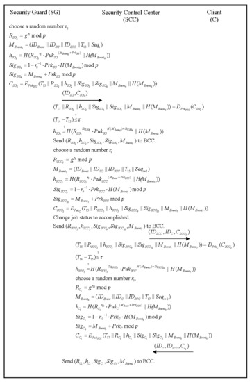
Figure 9.
The flowchart of the task accomplished phase.
Step 1. The SG selects a random , and computes the following parameter:
The timestamp will be appended to the event message:
The SG uses the hash function to compute the parameter :
The SG uses its private key and to compute the signatures as follows:
After that, the SG uses SCC’s public key to encrypt the message into a ciphertext :
Then, the SG sends to SCC.
Step 2. Once the SCC receives the cipher message at , the SCC uses its private key to decrypt the message:
Then, the SCC checks the validity of the timestamp:
If the timestamp interval is valid, then the SCC needs to verify the SG’s hash parameter:
If Equation (63) holds, the event status will be changed to “accomplished”. Then, the SCC sends and chains to the BCC.
Step 3. Next, a notification will be sent to the client to let the client know the current state of the security situation of the CH. The SCC selects a random , and computes the following parameter:
The timestamp will be appended to the event message:
The SCC uses the hash function to compute the parameter :
The SCC uses its private key and to compute the signatures as follows:
After that, the SCC uses the client’s public key to encrypt the message into a ciphertext :
Then, the SCC sends and chains to the BCC.
Meanwhile, the SCC sends to the client, and a notification will be sent to the client to let the client know the current state of the security situation of the CH.
Step 4. Once the client receives the cipher message at , the client uses its private key to decrypt the message:
Then, the client checks the validity of the timestamp:
If the timestamp interval is valid, then the client needs to verify SCC’s hash parameter:
If Equation (72) holds, then the client will reply to the SCC that the notification is received.
Step 5. The client selects a random , and computes the following parameter:
The timestamp will be appended to the event message:
The client uses the hash function to compute the parameter :
The client uses the private key and to compute the signatures as follows:
After that, the client uses the SCC’s public key to encrypt the message into a ciphertext :
Then, the C sends to the SCC.
Step 6. Once receiving the cipher message at , the SCC uses its private key to decrypt the message:
Then, the SCC checks the validity of the timestamp:
If the timestamp interval is valid, then the client needs to verify the client’s hash parameter:
If Equation (81) holds, the latest message will be sent and chained to the BCC.
Step 7. Then, the SCC selects a random number , and computes the following parameter:
The event ID, client’s ID, and SCC’s staff ID will be written to the event message with a timestamp :
The SCC uses the hash function to compute the parameter :
The SCC uses its private key and to compute the signatures as follows:
Then, the SCC sends and chains to the BCC.
3.9. Arbitration Phase
In this phase, if the client doubts the legality of a security event, the client needs to provide his/her ID, IMC ID, and event ID to the official agency (OA) to verify the validity of the event. The flowchart of the arbitration phase is shown in Figure 10.
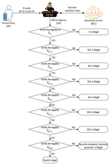
Figure 10.
The flowchart of the arbitration phase.
The detailed steps of this phase are as follows:
- Step 1.
- AP send to the OA.
- Step 2.
- The OA sends a request message with .
- Step 3.
- The BCC checks the signature from the OA; if it is valid, the BCC sends the validation data of the specific event ID to the OA. In every phase, the SCC needs to send the validation data to the BCC, and let the OA verify whether the event is legal or not. Every phase of the validation data is shown as follows:
Event trigger phase:
Task allocating phase:
Task accomplished phase:
- Step 4.
- The OA verifies the legality of the hash parameter :
If the equation holds, we go to the next step.
Otherwise, the event is illegal (hash value is not equal to the right, which means that the signature is not valid) when the C reads the event notification, so the C is illegal if the customer does not read the notification.
- Step 5.
- The OA verifies the legality of the hash parameter :
If the equation holds, go to the next step.
Otherwise, the event is illegal when the SCC sends a notification to the C, so the SCC is illegal.
- Step 6.
- The OA verifies the legality of the hash parameter :
If the equation holds, we go to the next step.
Otherwise, the event is illegal when the SG reports the tasks accomplished to the SCC, so the SG is illegal.
- Step 7.
- The OA verifies the legality of the hash parameter :
If the equation holds, we go to the next step.
Otherwise, the event is illegal when the SCC receives the accepted task message, so the SCC is illegal.
- Step 8.
- The OA verifies the legality of the hash parameter :
If the equation holds, we go to the next step.
Otherwise, the event is illegal when the SG accepts the task and replies to the SCC, so the SG is illegal.
- Step 9.
- The OA verifies the legality of the hash parameter :
If the equation holds, we go to the next step.
Otherwise, the event is illegal when the SCC allocates the task to the SG, so the SCC is illegal.
- Step 10.
- The OA verifies the legality of the hash parameter :
If the equation holds, we go to the next step.
Otherwise, the event is illegal when the SCC receives the message from the IMC, so the SCC is illegal.
- Step 11.
- The OA verifies the legality of the hash parameter :
If the equation holds, we go to the next step.
Otherwise, the event is illegal when the IMC in the client’s house sends an event trigger message to the SCC, so the security company’s technical personnel is illegal.
- Step 12.
- The OA judges that the event is legal, and sends the judgment to AP.
3.10. Key Recovery Phase
Access parties (including the client, security guard, and staff) need to register with the SCC, and the public key and private key will be issued to the parties. If the parties lose their private key, they can send a key recovery request to the SCC; the scenario is as follows:
- Step 1.
- The access party sends a key recovery request to the SCC, and the request message includes ID and details information.
- Step 2.
- The SCC receives the request, then checks the consistency of the information from the request message and smart contract automatically.
- Step 3.
- If the information from the accessing party is equal to the smart contract, then they re-register a new key pair from the BCC and update the new key pairs to the corresponding party’s information structure.
- Step 4.
- The SCC responds with a new key pair to the accessing party.
- Step 5.
- The access party receives the new key pair and the key recovery is done.
4. Security Analysis
4.1. Mutual Authentication
In this research, BAN logic is used to prove mutual authentication in the authentication algorithm [31], mainly to ensure that data is not modified during the phases.
The notation of BAN logic is described as below:
| P believes X. | |
| P sees X. | |
| P once said X. | |
| P has jurisdiction over X. | |
| Formula X is new. | |
| P has X as a public key. | |
| P and X may use the session key K to communicate with each other. | |
| The formula X is encrypted by K. |
In the initializing phase, the scheme makes sure that the legality is authenticated by the accessing party (AP) and the SCC. The main goals of the scheme are:
- G1:
- G2:
- G3:
- G4:
- G5:
- G6:
- G7:
- G8:
According to the authenticate algorithm, BAN logic is used to produce an idealized form as follows:
- M1: AP→SCC
- M2: SCC→AP
To analyze the proposed scheme, the following assumptions are made:
- A1:
- A2:
- A3:
- A4:
- A5:
- A6:
- A7:
- A8:
- Security control center authenticates access party.
By M1 and the seeing rule, derive:
Statement 1.
By A2 and the freshness rule, derive:
Statement 2.
By (Statement 1) and the message meaning rule derive:
Statement 3.
By (Statement 2), (Statement 3) and the nonce verification rule, derive:
Statement 4.
By (Statement 4) and the belief rule, derive (G4):
Statement 5.
By (Statement 5), A6, and the jurisdiction rule, derive (G3):
Statement 6.
By (Statement 4) and the belief rule, derive (G8):
Statement 7.
By (Statement 7), A8, and the belief rule, derive (G7):
Statement 8.
- b.
- Access party authenticates security control center.
By M1 and the seeing rule, derive:
Statement 9.
By A3 and the freshness rule, derive:
Statement 10.
By (Statement 9) and the message meaning rule derive:
Statement 11.
By (Statement 10), (Statement 11) and the nonce verification rule, derive:
Statement 12.
By (Statement 12) and the belief rule, derive (G2):
Statement 13.
By (Statement 13), A5 and the jurisdiction rule, derive (G1):
Statement 14.
By (Statement 12) and the belief rule, derive (G6):
Statement 15.
By (Statement 15), A7, and the belief rule, derive (G5):
Statement 16.
By (Statement 6), (Statement 8), (Statement 14), and (Statement 16), the accessing party and the SCC authenticate each other in the proposed scheme. The SCC authenticates the accessing party by:
The accessing party authenticates the SCC by:
Scenario: The attacker pretends to be the SCC and fetches data from the user.
Analysis: The attacker cannot obtain the message from the accessing party because our message transmission process is encrypted with the receiver’s public key. Only the person with the private key can decrypt the data. Both parties can check the correctness of the signature. Therefore, the attacker will not be able to pretend to be the SCC in the proposed method.
4.2. Traceable
Figure 11 shows the characteristics of the blockchain structure. Any event message received by SCC automatically chains the message with the sender’s signatures to the blockchain. The chaining flow is shown as follows:
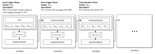
Figure 11.
The event message chaining process in the blockchain.
- (1)
- In the event trigger phase, once the event is triggered from the IMC in the client’s house, the SCC receives the message and sends to the BCC, then the BCC calculates the hash with the message, and creates that information as the first block.
- (2)
- Next, the SCC sends to the BCC, then the BCC calculates the hash value of the first block and chains that information as the second block.
- (3)
- In the task allocation phase, the SCC sends to the BCC, then the BCC calculates the hash value with the message and hash value in the second block and chains that information as the third block.
Continuously, when any event message needs to chain to the BCC, the SCC needs to send the parameters, the signatures, and the message from the sender, then calculate the current block’s hash value with the message and the previous block’s hash value. Therefore, the processing of the event can be recorded in detail and can be traced.
The phase of creating the blockchain with signatures is defined as follows:
- (1)
- Event-trigger phase
The message from the IMC in the client’s house is:
SCC’s staff confirm received the message from the IMC:
- (2)
- Task allocating phase
The messages are sent to the SG:
The message from the SG is:
SCC’s staff confirm received the messages from the SG:
- (3)
- Task accomplished phase
The message from the SG is:
The messages are sent to the C:
The message from the C is:
SCC’s staff confirm the received messages from the C:
Therefore, the accessing party can easily track and verify the transactions via the blockchain.
4.3. Integrity
To preserve the integrity of the data in this paper, we used a public key, a private key, and digital signatures. When a malicious person modifies the data, the receiver can verify whether the data has been modified or not by verifying the signatures. The user can use the receiver’s public key to encrypt data for transmission. Malicious people are not able to obtain the encrypted data because they do not have a valid private key, so he/she is unable to access and tamper with the data.
In the information transmission process, preventing the modification of transmitted data is as follows: Equations (21), (22), (30), (31), (35), (36), (44), (45), (53), (54), (58), (59), (67), (68), (76), (77), (85) and (86).
Scenario: The attacker intercepts the message from the SCC authority to the accessing party and tampers with the message before sending it to the accessing party.
Analysis: The attacker will fail because our proposed method uses the receiver’s public key to encrypt the data, and only the receiver’s private key can decrypt the data. Therefore, when the attacker intercepts the message, the attacker cannot decrypt the message and maliciously modify the data.
4.4. Non-Repudiation
Non-repudiation is achieved in our proposed method. In every communication phase, the sender must sign their private key with the message; when the receiver receives the message, they must verify the hash value from the sender. If the equation is equal, the signatures are valid. So the message that is sent by the sender will have the ability of non-repudiation. Table 3 shows the non-repudiation of the proposed scheme.
Table 3.
Non-repudiation of the proposed scheme.
4.5. Against Known Attacks
4.5.1. Man-in-the-Middle Attack
In this attack, the attacker may try to pretend to be any accessing party in every phase. The attacker will try to intercept and tamper with the data. However, all messages that are created or updated from the main role from the client’s house and security company can be effectively authenticated through signatures in our proposed method, so it is difficult to tamper with the data during communication.
For example, in the authentication phase, the AP encrypts the message with the SCC’s public key in Equation (6), then generates the chipper message . Next, the AP sends to the SCC, and the receiver decrypts with the SCC’s private key in Equation (7). The related formula is as follows:
- (1)
- Authentication phase
- AP->SCC
- SCC->AP
- (2)
- Event-trigger phase
- IMC->SCC
- (3)
- Task allocating phase
- SCC->SG
- SG->SCC
- (4)
- Task accomplished phase
- SG->SCC
- SCC->C
- C->SCC
Therefore, the encryption and decryption scheme in every phase can effectively prevent man-in-the-middle attacks.
4.5.2. Replay Attack
An attacker intercepts the data from the communication, then sends the same data to the receiver, pretending to be the sender. In our method, we use a timestamp mechanism in every communication between the sender and receiver to prevent this kind of attack.
For example, in the authentication phase, the accessing party is encrypted at a timestamp in the cipher message and sends it to the SCC. The SCC decrypts the message and generates a timestamp that represents the received time, then checks the time difference between and . If the time is over the parameter , that means that the message sending time is too long and it may have been intercepted by an attacker. The related formula is as follows:
Our method also added a sequential number in the message from a sender; for example, in the authentication phase, a sequential ID generated randomly from the AP, in the next round of messages from the SCC will increase the to . It is bound with the message and sent to the AP; the AP receives the message and validates the sequential ID and checks if it is in the same sequence.
4.5.3. Side-Channel Attack
In the proposed scheme, it is hard to retrieve the private key via a side-channel attack. For every message that sends from the sender, the sender needs to select a random number and compute a parameter. For example, in the authentication phase, the AP selects a random number , and computes the following parameter:
Then AP uses the hash function and to compute the parameter :
The AP also uses to compute the signatures as follows:
Therefore, it is hard for the attacker to attack due to the randomized number.
4.5.4. Forgery Attack
In our scheme, it is difficult for an attacker to forge the message to the SCC; the received message will verify the identity of the accessing party. Table 3 in Section 4.4 shows all the verification equations of the proposed method. We have implemented and modified the ECDSA; the verification of the ECDSA can be verified by using the method introduced in Section 2.2. Based on the security of the Elliptic Curve Digital Signature Algorithm (ECDSA), it is a discrete logarithm problem. The ECDSA for the details of the proof refers to Section 8.1 of [29].
We also give two examples of verification derived for checking the hash value. They are shown as follows:
- (1)
- In the authentication phase, the verification is verified as follows:
- (2)
- In the event-trigger phase, the verification is derived as follows:
4.6. Threat Models in the Communication Phase
Next, we will discuss the scenarios of some threat models in the communication phase.
- (1)
- The IoT is disconnected from the IoT main controller: The IoT devices in the client’s house send a “keep-alive” signal to the main controller every number of seconds. Therefore, the main controller is able to confirm that the IoT is still alive. Some situations will cause IoT devices to disconnect from the main controller. For example, power loss, low battery, and device aging. If the main controller does not receive the “keep-alive” signal from one of the IoT devices, the controller will send an event automatically to the SCC, and the SCC will allocate the task to the security guard to solve the problem immediately.
- (2)
- The IMC in the client’s house is disconnected from the SCC: The SCC will ask the IMC in the client’s house automatically in a routine job; the main controller needs to respond with an alive message to the BCC. If the main controller does not receive the response message, the SCC will generate an event to ask the SG to solve the problem instantly.
- (3)
- Fake message impersonated from the IMC: Every communication between the IoT main controller and the SCC can be forged by a third party. To prevent this forgery security problem, the message sent between the IMC and the SCC communicate with the session key via a secure channel. Details will be described in the next section.
- (4)
- False alarm with the IoT: If IoT devices are tuned in the IMC, the probability of a false alarm in the IoT is very low. If it unfortunately happens, the alarm will be checked by the SCC, and SCC’s staff will check the camera manually to determine if there is a problem.
5. Discussion
5.1. Computation Cost
In Table 4, we analyze the computational costs of each phase. We use the asymmetrical, symmetrical, hash function, addition/subtraction operation, multiplication/division operation, and exponential as the basis for calculating the cost.
Table 4.
Computation costs of the proposed scheme.
5.2. Communication Performance
In Table 5, we analyze the communication costs at every phase. In a 4G environment, the maximum transmission speed is 100 Mbps [46]. In a 5G environment, the maximum transmission speed is 20 Gbps [47]. In our analysis, it was assumed that an access or event message required 304 bits, a hash operation required 160 bits, a signature operation required 1024 bits, and the other message required 80 bits. The 304 bits of an access or event message is assumed by the maximum length of the message (five IDs and one timestamp) that sends at the allocating task phase, which is 5 × 80 bits + 1 × 32 bits = 432 bits.
Table 5.
Communication costs of the proposed scheme.
The communication costs are calculated depending on the number of messages. For example, in the authentication phase, the AP sends one access message, two hash values, two signatures, and three other messages to the SCC. After that, the SCC sends two signatures and five other messages. In total, it requires 1 × 432 bits + 2 × 160 bits + 4 × 1024 bits + 8 × 80 bits = 5488 bits. In a 4G environment, the maximum transmission speed is 100 Mbps and it only takes 0.054 ms to transfer all the messages. In a 5G environment, the maximum transmission speed is 20 Gbps; the transmission time needed is only 0.27 us to complete the authentication phase.
5.3. Comparison
In this section, we compare related works which involve the security analysis in Table 6. Compared to the related works, some of the proposed schemes lack complete functionality (for example, blockchain, smart contract, or control center). Our scheme focuses on proposing a security service that involves blockchain and smart contract technologies to ensure that the event messages that generate and send from the accessing party to the security control center are fully recorded to the blockchain center. Therefore, compared to other schemes, our scheme achieves the full safety security protocol and we also make a full security analysis including mutual authentication, traceability, integrity, non-repudiation, and threat models.
Table 6.
Comparison of related works and the proposed study.
6. Conclusions
This study aimed to propose a traceable security system. We involved smart contracts and blockchain technologies in this scheme. Every record from the accessing party to the blockchain center is sent and chained. We used the characteristics of the blockchain center to solve the trust problem between the security company and the client. We also proposed a fair and clear arbitration mechanism for the clarification of responsibilities, which was not available in the security industry in the past.
The proposed method achieves the following goals. Firstly, the characteristic data through the blockchain can be publicly verified and the information will not be modified. Secondly, we used BAN logic to prove mutual authentication. Thirdly, the official agency is able to query the information with the signature from the accessing party and validate the legality of the event record. Fourthly, the proposed method achieves traceability, integrity, and non-repudiation. The method can also resist man-in-the-middle attacks, replay attacks, and forgery attacks. In this study, we also considered the threat models during the communication phase. Every message from the IoT main controller in the client’s house will not be able to send a false alarm to the security control center. It also allows the control center to stay connected with the IoT main controller at any time.
In future works, the proposed method of a blockchain center can be expanded to become a blockchain alliance with multiple security companies able to connect to blockchain alliance services with traceability and authentication.
Author Contributions
The authors’ contributions are summarized below. Z.-Y.L. and C.-L.C. made substantial contributions to conception and design. Z.-Y.L. and C.-L.C. were involved in drafting the manuscript. Z.-Y.L. and Y.-Y.D. acquired data and analyses and conducted the interpretation of the data. The critically important intellectual content of this manuscript was revised by H.-C.L. and Y.-Y.D. All authors have read and agreed to the published version of the manuscript.
Funding
The APC was funded by Chaoyang University of Technology.
Institutional Review Board Statement
This study is based entirely on theoretical basic research. It does not involve humans.
Informed Consent Statement
This study is based entirely on theoretical basic research. It does not involve humans.
Data Availability Statement
The data used to support the findings of this study are available from the corresponding author upon request.
Conflicts of Interest
The authors declare no conflict of interest.
References
- Nalla, M.K.; Crichlow, V.J. Have the standards for private security guards become more stringent in the post 9/11 era? An assessment of security guard regulations in the US from 1982 to 2010. Secur. J. 2017, 30, 523–537. [Google Scholar] [CrossRef]
- FBI UCR: Crime in the U.S. Available online: https://ucr.fbi.gov/crime-in-the-u.s/ (accessed on 6 January 2021).
- Crime in England and Wales: Year Ending June 2019. Available online: https://www.ons.gov.uk/peoplepopulationandcommunity/crimeandjustice/bulletins/crimeinenglandandwales/yearendingjune2019 (accessed on 6 January 2021).
- Nemeth, C.P. Private Security: An Introduction to Principles and Practice, 1st ed.; CRC Press: Boca Raton, FL, USA, 2017. [Google Scholar]
- Lin, H.; Bergmann, N. IoT Privacy and Security Challenges for Smart Home Environments. Information 2016, 7, 44. [Google Scholar] [CrossRef]
- Hassija, V.; Chamola, V.; Saxena, V.; Jain, D.; Goyal, P.; Sikdar, B. A Survey on IoT Security: Application Areas, Security Threats, and Solution Architectures. IEEE Access 2019, 7, 82721–82743. [Google Scholar] [CrossRef]
- Nakamoto, S. Bitcoin: A Peer-to-Peer Electronic Cash System. Available online: https://bitcoin.org/bitcoin.pdf (accessed on 29 December 2020).
- Feroz Ahmad, A.; Prashant, K.; Gulshan, S.; Med Salim, B. Bitcoin: Digital Decentralized Cryptocurrency. In Handbook of Research on Network Forensics and Analysis Techniques; Gulshan, S., Prabhat, K., Gupta, B.B., Suman, B., Nilanjan, D., Eds.; IGI Global: Hershey, PA, USA, 2018; pp. 395–415. [Google Scholar] [CrossRef]
- Khatoon, A. A Blockchain-Based Smart Contract System for Healthcare Management. Electronics 2020, 9, 94. [Google Scholar] [CrossRef]
- Tanwar, S.; Parekh, K.; Evans, R. Blockchain-based electronic healthcare record system for healthcare 4.0 applications. J. Inf. Secur. Appl. 2020, 50, 102407. [Google Scholar] [CrossRef]
- Zarour, M.; Ansari, M.T.J.; Alenezi, M.; Sarkar, A.K.; Faizan, M.; Agrawal, A.; Kumar, R.; Khan, R.A. Evaluating the Impact of Blockchain Models for Secure and Trustworthy Electronic Healthcare Records. IEEE Access 2020, 8, 157959–157973. [Google Scholar] [CrossRef]
- Hu, Y.; Manzoor, A.; Ekparinya, P.; Liyanage, M.; Thilakarathna, K.; Jourjon, G.; Seneviratne, A. A Delay-Tolerant Payment Scheme Based on the Ethereum Blockchain. IEEE Access 2019, 7, 33159–33172. [Google Scholar] [CrossRef]
- Lin, C.; He, D.; Huang, X.; Khan, M.K.; Choo, K.R. DCAP: A Secure and Efficient Decentralized Conditional Anonymous Payment System Based on Blockchain. IEEE Trans. Inf. Forensics Secur. 2020, 15, 2440–2452. [Google Scholar] [CrossRef]
- Zhao, Y.; Li, Y.; Mu, Q.; Yang, B.; Yu, Y. Secure Pub-Sub: Blockchain-Based Fair Payment With Reputation for Reliable Cyber Physical Systems. IEEE Access 2018, 6, 12295–12303. [Google Scholar] [CrossRef]
- Chen, Q.; Srivastava, G.; Parizi, R.M.; Aloqaily, M.; Ridhawi, I.A. An incentive-aware blockchain-based solution for internet of fake media things. Inf. Process. Manag. 2020, 57, 102370. [Google Scholar] [CrossRef]
- Li, J.; Grintsvayg, A.; Kauffman, J.; Fleming, C. LBRY: A Blockchain-Based Decentralized Digital Content Marketplace. In Proceedings of the 2020 IEEE International Conference on Decentralized Applications and Infrastructures (DAPPS), Oxford, UK, 3–6 August 2020; pp. 42–51. [Google Scholar]
- Ma, Z.; Jiang, M.; Gao, H.; Wang, Z. Blockchain for digital rights management. Future Gener. Comput. Syst. 2018, 89, 746–764. [Google Scholar] [CrossRef]
- Smith, S.; Ellis, J.; Abrams, R. Central Alarm Stations and Dispatch Operations. In The Professional Protection Officer; Butterworth-Heinemann: Oxford, UK, 2010; pp. 89–103. [Google Scholar] [CrossRef]
- Liu, H.; Han, D.; Li, D. Fabric-iot: A Blockchain-Based Access Control System in IoT. IEEE Access 2020, 8, 18207–18218. [Google Scholar] [CrossRef]
- Lin, C.; He, D.; Huang, X.; Choo, K.-K.R.; Vasilakos, A.V. BSeIn: A blockchain-based secure mutual authentication with fine-grained access control system for industry 4.0. J. Netw. Comput. Appl. 2018, 116, 42–52. [Google Scholar] [CrossRef]
- Mbarek, B.; Ge, M.; Pitner, T. Blockchain-Based Access Control for IoT in Smart Home Systems; Springer: Cham, Switzerland, 2020; pp. 17–32. [Google Scholar] [CrossRef]
- Alkhammash, M.; Beloff, N.; White, M. An Internet of Things and Blockchain Based Smart Campus Architecture; Springer: Cham, Switzerland, 2020; pp. 467–486. [Google Scholar]
- Lyu, Q.; Zheng, N.; Liu, H.; Gao, C.; Chen, S.; Liu, J. Remotely Access “My” Smart Home in Private: An Anti-Tracking Authentication and Key Agreement Scheme. IEEE Access 2019, 7, 41835–41851. [Google Scholar] [CrossRef]
- Fakroon, M.; Alshahrani, M.; Gebali, F.; Traore, I. Secure remote anonymous user authentication scheme for smart home environment. Internet Things 2020, 9, 100158. [Google Scholar] [CrossRef]
- Buterin, V. A next-generation smart contract and decentralized application platform. Ethereum White Pap. 2014, 3, 36. [Google Scholar]
- Hjálmarsson, F.Þ.; Hreiðarsson, G.K.; Hamdaqa, M.; Hjálmtýsson, G. Blockchain-Based E-Voting System. In Proceedings of the 2018 IEEE 11th International Conference on Cloud Computing (CLOUD), San Francisco, CA, USA, 2–7 July 2018; pp. 983–986. [Google Scholar]
- Yiu, N.C.K. An Empirical Analysis of Implementing Enterprise Blockchain Protocols in Supply Chain Anti-Counterfeiting and Traceability. Cryptogr. Secur. 2021. [Google Scholar] [CrossRef]
- Vanstone, S. Responses to NIST’s proposal. Commun. ACM 1992, 35, 50–52. [Google Scholar]
- Johnson, D.; Menezes, A.; Vanstone, S. The Elliptic Curve Digital Signature Algorithm (ECDSA). Int. J. Inf. Secur. 2001, 1, 36–63. [Google Scholar] [CrossRef]
- Elaine Barker, A.R. Transitioning the Use of Cryptographic Algorithms and Key Lengths; National Institute of Standards and Technology: Washington, DC, USA, 2019. [Google Scholar]
- Burrows, M.; Abadi, M.; Needham, R. A logic of authentication. ACM Trans. Comput. Syst. 1990, 8, 18–36. [Google Scholar] [CrossRef]
- Sierra, J.M.; Hernández, J.C.; Alcaide, A.; Torres, J. Validating the Use of BAN LOGIC; Springer: Berlin/Heidelberg, Germany; pp. 851–858.
- Zhao, Q.; Chen, S.; Liu, Z.; Baker, T.; Zhang, Y. Blockchain-based privacy-preserving remote data integrity checking scheme for IoT information systems. Inf. Process. Manag. 2020, 57, 102355. [Google Scholar] [CrossRef]
- Tasnim, M.A.; Omar, A.A.; Rahman, M.S.; Bhuiyan, M.Z.A. CRAB: Blockchain Based Criminal Record Management System. In Proceedings of Security, Privacy, and Anonymity in Computation, Communication, and Storage; Springer: Cham, Switzerland, 2018; pp. 294–303. [Google Scholar]
- Servida, F.; Casey, E. IoT forensic challenges and opportunities for digital traces. Digit. Investig. 2019, 28, S22–S29. [Google Scholar] [CrossRef]
- Alblooshi, M.; Salah, K.; Alhammadi, Y. Blockchain-based Ownership Management for Medical IoT (MIoT) Devices. In Proceedings of the 2018 International Conference on Innovations in Information Technology (IIT), Al Ain, United Arab Emirates, 18–19 November 2018; pp. 151–156. [Google Scholar]
- Mohamed, K.S. Cryptography Concepts: Integrity, Authentication, Availability, Access Control, and Non-repudiation. In New Frontiers in Cryptography: Quantum, Blockchain, Lightweight, Chaotic and DNA; Mohamed, K.S., Ed.; Springer International Publishing: Cham, Switzerland, 2020; pp. 41–63. [Google Scholar] [CrossRef]
- Jin, H.; Jiang, H.; Zhou, K. Dynamic and Public Auditing with Fair Arbitration for Cloud Data. IEEE Trans. Cloud Comput. 2018, 6, 680–693. [Google Scholar] [CrossRef]
- Conti, M.; Dragoni, N.; Lesyk, V. A Survey of Man In The Middle Attacks. IEEE Commun. Surv. Tutor. 2016, 18, 2027–2051. [Google Scholar] [CrossRef]
- Feng, Y.; Wang, W.; Weng, Y.; Zhang, H. A Replay-Attack Resistant Authentication Scheme for the Internet of Things. In Proceedings of the 2017 IEEE International Conference on Computational Science and Engineering (CSE) and IEEE International Conference on Embedded and Ubiquitous Computing (EUC), Guangzhou, China, 21–24 July 2017; pp. 541–547. [Google Scholar]
- Saadeh, M.; Sleit, A.; Qatawneh, M.; Almobaideen, W. Authentication Techniques for the Internet of Things: A Survey. In Proceedings of the 2016 Cybersecurity and Cyberforensics Conference (CCC), Amman, Jordan, 2–4 August 2016; pp. 28–34. [Google Scholar]
- Samuel, S.S.I. A review of connectivity challenges in IoT-smart home. In Proceedings of the 2016 3rd MEC International Conference on Big Data and Smart City (ICBDSC), Muscat, Oman, 15–16 March 2016; pp. 1–4. [Google Scholar]
- Kocher, P.; Jaffe, J.; Jun, B.; Rohatgi, P. Introduction to differential power analysis. J. Cryptogr. Eng. 2011, 1, 5–27. [Google Scholar] [CrossRef]
- Mamiya, H.; Miyaji, A.; Morimoto, H. Efficient Countermeasures against RPA, DPA, and SPA; Springer: Berlin/Heidelberg, Germany, 2004; pp. 343–356. [Google Scholar]
- Genkin, D.; Pachmanov, L.; Pipman, I.; Tromer, E.; Yarom, Y. ECDSA Key Extraction from Mobile Devices via Nonintrusive Physical Side Channels. In Proceedings of the 2016 ACM SIGSAC Conference on Computer and Communications Security, Vienna, Austria, 24–28 October 2016; pp. 1626–1638. [Google Scholar]
- Khan, A.H.; Qadeer, M.A.; Ansari, J.A.; Waheed, S. 4G as a Next Generation Wireless Network. In Proceedings of the 2009 International Conference on Future Computer and Communication, Kuala Lumpur, Malaysia, 3–5 April 2009; pp. 334–338. [Google Scholar]
- Kaur, K.; Kumar, S.; Baliyan, A. 5G: A new era of wireless communication. Int. J. Inf. Technol. 2020, 12, 619–624. [Google Scholar] [CrossRef]
Publisher’s Note: MDPI stays neutral with regard to jurisdictional claims in published maps and institutional affiliations. |
© 2021 by the authors. Licensee MDPI, Basel, Switzerland. This article is an open access article distributed under the terms and conditions of the Creative Commons Attribution (CC BY) license (http://creativecommons.org/licenses/by/4.0/).