1. Introduction
Composite materials are increasingly used in ultralight aerospace designs. Composite load-bearing structures allow design and manufacture unmanned aerial vehicles (UAVs) that weigh no more than a dozen kilograms and have wingspans exceeding 20 m. The strength of the composite materials is no longer a noticeable barrier. High-strength composite materials that significantly reduce weight are already widely available. However, other problems have not been solved so far. One of the most important is related to the loss of stability [
1,
2], which is the primary criterion for shaping such design structure. Among the other problems are the use of technologies to produce large-size structures from materials with thicknesses much less than 1 mm, and the challenge of designing large-size structures with extremely thin walls [
3]. Forming a highly flexible structure, especially in aviation operating conditions—i.e., significant changes in geometry under varying load conditions—and aeroelastic phenomena associated with the operation of such an arrangement are issues that must be considered [
4]. Structural shaping to meet the abovementioned requirements is becoming a fundamental issue. It is essential to analyze the spectrum of possible solutions at the concept and preliminary design stages in such conditions [
5,
6,
7,
8,
9].
Time-consuming analyses and geometric modelling of structures make this process ineffective. Therefore, in such a particular case, using highly flexible thin-walled aircraft designs, knowledge-based engineering methods, and specific generative modelling was proposed [
10,
11]. This should allow the rapid generation of solutions and automate the support structure’s modelling process based on simplified design criteria.
The generative model’s operation is combined with a set of simplified verification methods based on Finite Element Method (FEM) used for a simplified structure model based on integrated load states. This method allows one to quickly evaluate individual solutions and choose a solution for further optimization analysis, which is carried out in the following design stages [
10,
11].
To solve the problem mentioned in the introduction, the authors propose a design methodology based on the use of the generative modelling technique, and the principles of forming highly flexible aircraft structures and thin-film composites with special attention focused on the FEM validation of the preliminary geometry [
12,
13].
The background of these issues is presented in
Section 2 (state of the art) and the methodology proposed by the authors is described in
Section 3—developed methodology. For the methodology verification, the example of a HALE UAV built by the authors was used, and verification details are presented in
Section 4—use case. The article ends with conclusions and an assessment of the effectiveness of the methodology used.
2. State of the Art
In the design processes, strictly defined or even standardized activities are used, including the design of repeatable parts of the structure. A common practice is to make extensive use of these opportunities through Design Reuse (DR). Computer Aided Design (CAD) techniques make use of specific model solutions (CAD models) along with the principles of determining their features, which make the design process much easier [
14].
The idea of using DR in the CAD systems environment gives rise to new possibilities, from simple parameterization to complex Generative Models (GMs). These methods can be applied to small parts, elements, and entire components, and products [
10]. Such automation of constructing a geometric model in the CAD environment is also called Geometry-Based Design Automation (GBDA). It is not the only form of automation of the design process. Still, it stands out due to the widespread use of CAD systems in the engineering, automotive, aviation industries, etc. In individual CAD systems, tool-based forms of geometric modelling are quite different. These range from programming and scripting techniques, through extensive construction of various template complexity levels (high-level CAD templates), allowing for the integration of multiple forms of knowledge into the geometric model.
Automation itself accelerates the design process at some stage—e.g., it allows for faster generation of geometry and leads to the designer being able to study a much larger space of possible solutions simultaneously [
1]. Such automation opens the way to integrating geometric modelling into optimization processes and, with complex multidisciplinary problems, to Multidisciplinary Design Optimization (MDO). However, it should be remembered that there is no definite methodology for the automation of design processes. It is also impossible to answer which of these works can be automated and with what techniques. This applies to the application of knowledge-based engineering methods. The proposed solutions are good practices rather than principles [
15].
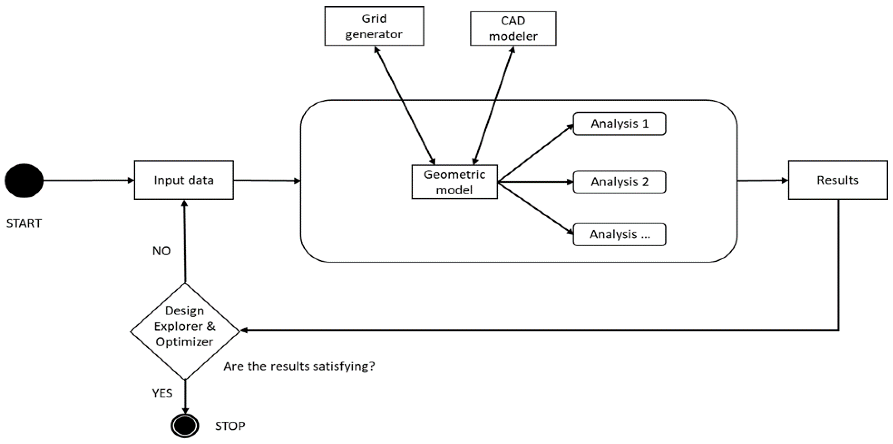
In a multidisciplinary approach, the geometric model plays a strategic role. So, it is possible to implement the MDO approach [
16]:
- (a)
without considering the geometric model (
Figure 1);
- (b)
with a geometric model implemented for visualization of results (
Figure 2);
- (c)
with a simplified geometric model in the form of the parametric grid used for optimization analyses (
Figure 2);
- (d)
with a detailed geometric model used in the optimization loop (
Figure 2).
In both approaches, a and b, neither the geometric model nor the data that are used in the optimization process are saved in the form of a geometric model. There is no need to make such a model for the calculations themselves, which significantly speeds up the optimization loop time and reduces the labor and computational demand. The aforementioned approaches are used when such a model, by definition, is not needed in methods that use mathematical models of phenomena or semiempirical or statistical methods. If the model is built based on the geometric data used for the calculations, it is used by experts for visualization and comparative purposes only, which helps to interpret the results.
In the second group of the optimization approaches (c, d), we deal with a geometric model in the calculation process. The geometry used for calculations is taken from the model, or the geometry data used in the calculations are visualized through the visualization interface. Typically, these methods are used when some form of geometric structure model is required—e.g., the finite element method (FEM) or Vortex Lattice Method (VLM) or any calculation method using geometry input [
11]. Depending on the calculation method and the form of the model used, the form of the model itself may be simplified or integrated into a complex CAD model. In both the first and second forms, generative models can be used to assist in the generation of geometry.
Especially for the latter and multidisciplinary problems, the optimization computation models can differ significantly from each other. Two types of Simultaneous Analysis and Design (SAND) and Nested Analysis and Design (NAND) models stand out from the several different possible configurations of multidisciplinary computation. With a SAND configuration, the disciplinary optimizer simultaneously determines the value of both design and state variables at a disciplinary level. In contrast, in the case of a NAND framework, the optimizer only determines the design variables, with state variables needing to be calculated at each iteration [
17].
Automation of the design process in aviation applications and the application to the supporting structures of flying objects are the subject of intensive research. This is not only because of:
- (1)
The need to organize the design process, increase its efficiency and record, and integrate knowledge and experience resources from other sources and previous projects.
- (2)
Integration of these automation procedures in more extensive structural improvement and optimization procedures considering structural analysis—Computational Structural Mechanics (CSM). In terms of this approach, there are three main areas of application of the above type of analysis. The most characteristic examples include the consideration of topology optimization, the use of composite materials, and the definition of the structural layout.
- (3)
Integration of load-bearing structure automation procedures in more extensive methods for improving and optimizing structures also considers other fields [
6]. In terms of this approach, such relationships are most often investigated in aeroelastic analysis, aircraft performance, and costs or market demands.
Such integrated approaches are also called MDO (multidisciplinary design optimization) [
7,
16,
18], Model-Based Design (MBD) [
8,
19], Model-Based Optimization (MBO) [
20].
Usually, CSM methods are used as high-fidelity models in the detailed design phase and sometimes also as medium-fidelity models in the preliminary design stage on the simplified geometry. Although, in the conceptual design phase there is often a need to obtain alternative concepts load-bearing structures. On the other hand, relying on simplified geometry encounters a severe problem precisely because of the large amount of work involved in generating alternative concepts of support structures, which often exceed the time required for numerical analyses and their interpretation. Such a bottleneck is usually eliminated using methods of automating the process of generating a geometric model. It is necessary to use a model with a high degree of detail, considering the aspect of manufacturing technology, design dependencies, the engineering correctness of the model, and structural consistency. Generative modeling yields good results [
10].
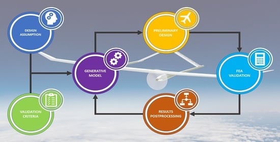
Generative modelling (GM) is one of the most popular knowledge-based engineering techniques used in the design field [
8,
15,
21]. The main idea behind GM is to elaborate the CAD model, which will automatically, or at least semiautomatically, generate the model’s geometry based on the design requirements and integrated knowledge [
9,
15,
22]. The general schema of GM functioning is presented in
Figure 3.
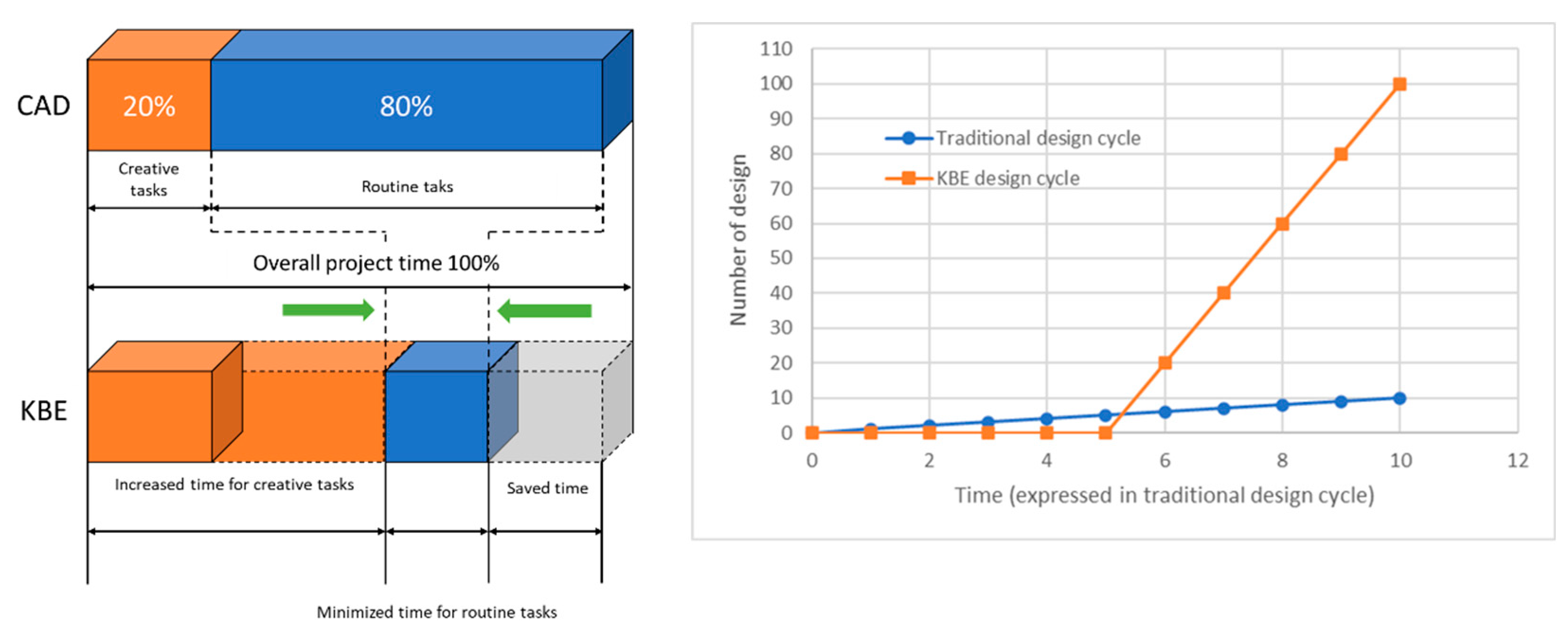
The essential advantage of using the GM, which is one of knowledge-based engineering (KBE) methods of design automation, is the possibility to reduce the time a designer spends on some routine design tasks and put more effort into creative parts of the project, as presented in
Figure 4 [
15,
22,
23]. Thanks to this, it is possible to develop a new approach to some problems, which may be better and more efficient than those currently used. On the other side of the coin, development of the GM is time-consuming and usually requires the assistance of an expert in the field [
15,
21]. Moreover, the number of knowledge engineers who are essential during knowledge acquisition and structuralizing is limited [
15,
19,
23]. However, the effort put into the GM development may bring more benefits in the long-term perspective, especially in the number of projects that can be realized in a shorter time and with less effort, as presented in
Figure 4 [
9,
15,
23].
3. Developed Methodology
The principal authors’ purpose is to simplify the conceptual stage of the aircraft design as much as possible by using generative modelling techniques combined with FEM analysis. The result of these actions is the systematic approach presented in
Figure 5 in a simple schema. Because the design process based on the GMs is slightly different from the traditional design method, the authors tried to adapt the generation procedure to specific requirements of the FEM validation.
At different stages of the project development, different approaches to defining material data were used. In the initial stages, the isotropic material model was used, and in the next stages the anisotropic model was used for composite materials. The latter was based on general manufacturer data in the initial stages and then the tests performed on samples with a given structure.
3.1. CAD Model Development
As we can see in the schema in
Figure 5, the first stage of the process was the generation of the load-bearing structure’s primary geometry. In this process, the series of the GMs were in use. Each component, such as a spar, a rib or a stringer, was designed individually with its own set of parameters.
The only common thing that connects all components is the geometrical input in the form of airfoil curves for the next sections of the wing. In the proposed approach, each section of a wing is designed independently, and as a section, we mean a part of a wing which contains the same type of an airfoil profile. Using the shared geometrical data makes any change in the geometrical input forces automatically rebuild all related elements without user attention.
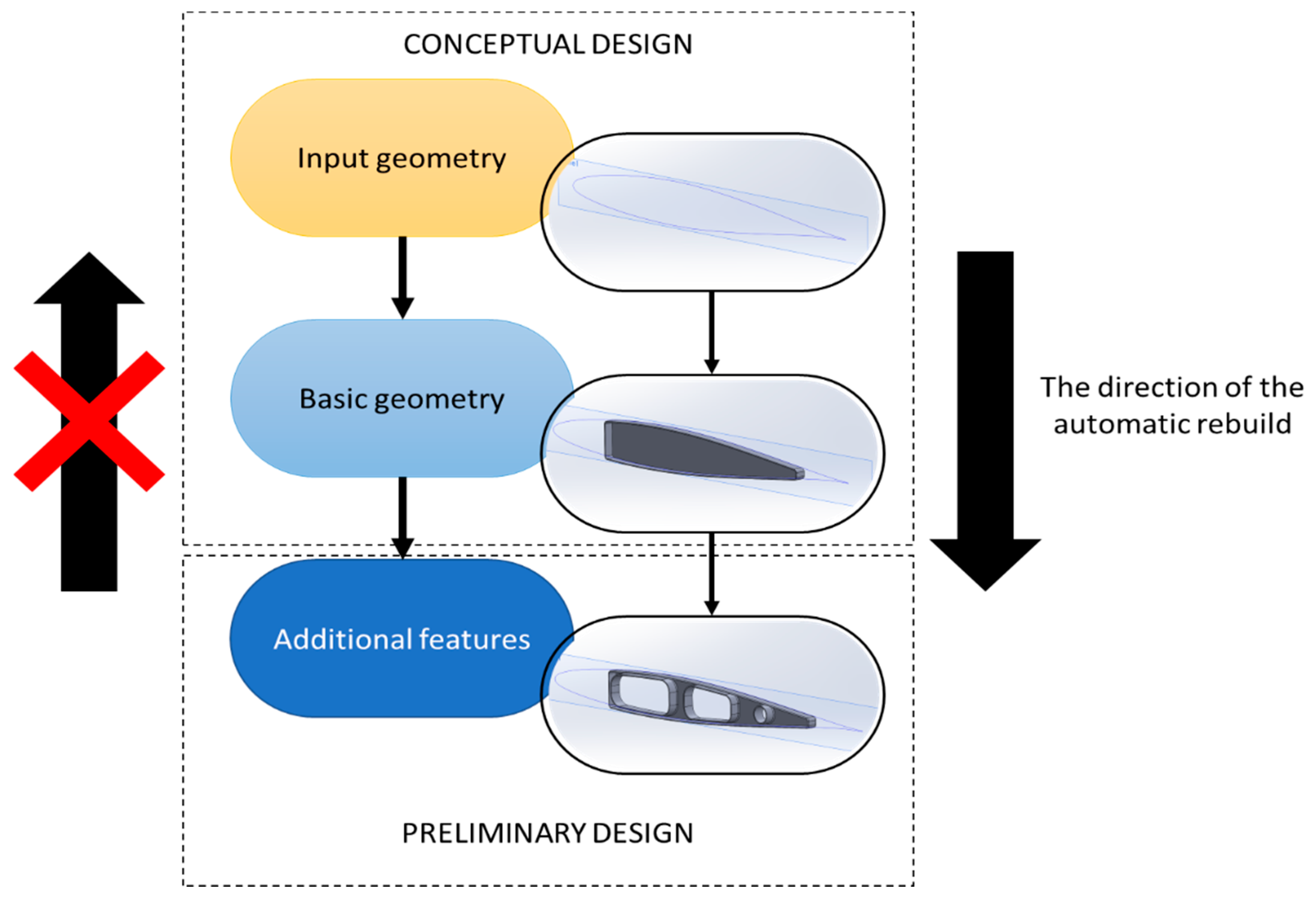
The same approach was used in the stage of further development of the models. If the FEM validation results were satisfying, the user could add additional features related to the manufacturing method or specific requirements of the used material or technology.
In the presented approach, the GMs for additional features use existing geometry, from the previous stage of the design process, as the geometrical input. That creates a hierarchical feedback loop that forces automatically rebuilding all related elements—i.e., change of the airfoil causes revamp of the spar. Changes in the spar make changes in the spar features. The sequence of changes in this hierarchy is shown in
Figure 6.
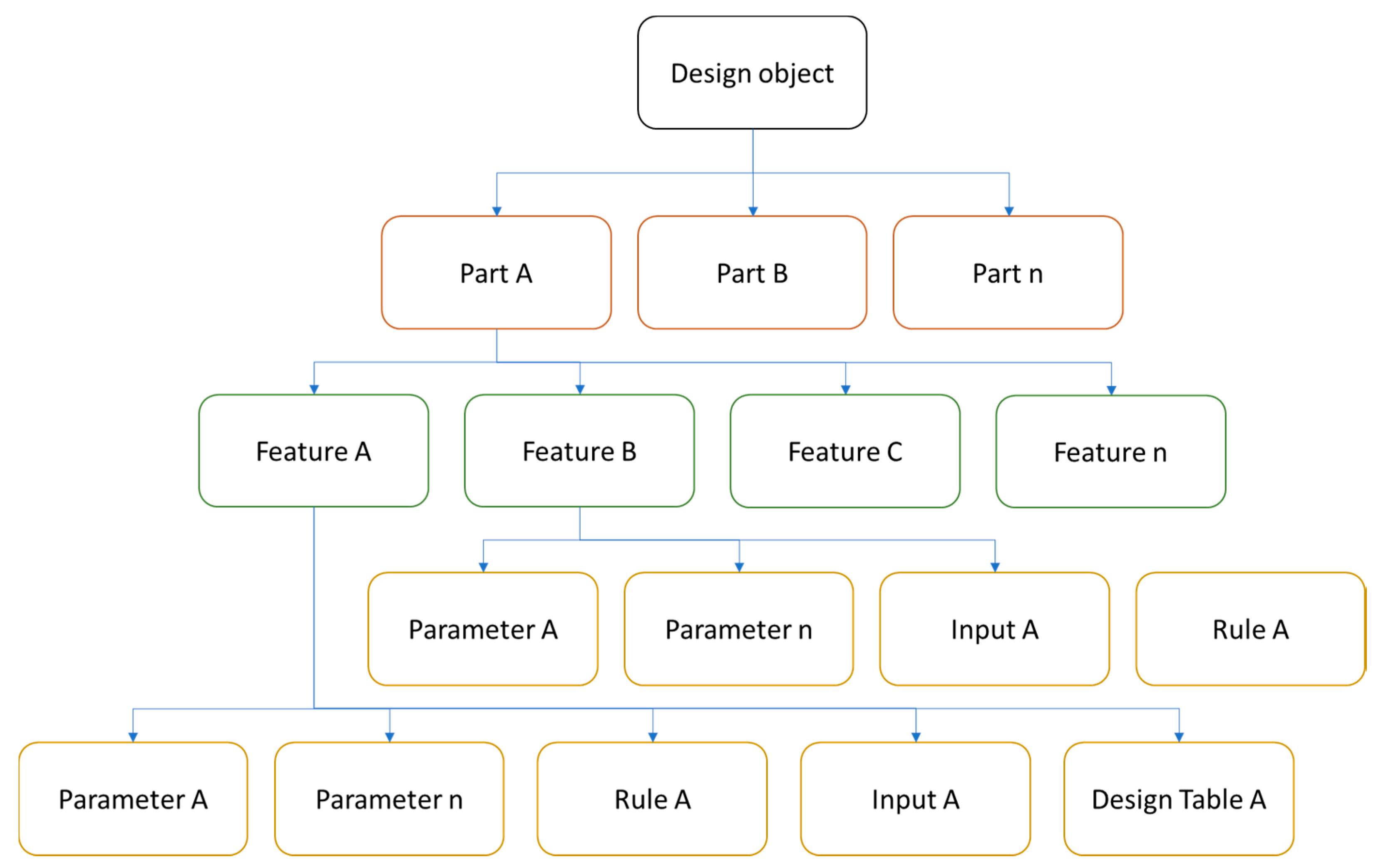
In the GM elaboration process it is essential to decompose the design object into smaller and simpler objects to generate. The authors prepared a series of hierarchical diagrams where all features were extracted and described by parameters, required geometrical inputs, rules, etc. In
Figure 7, the main idea of the decomposition process is presented.
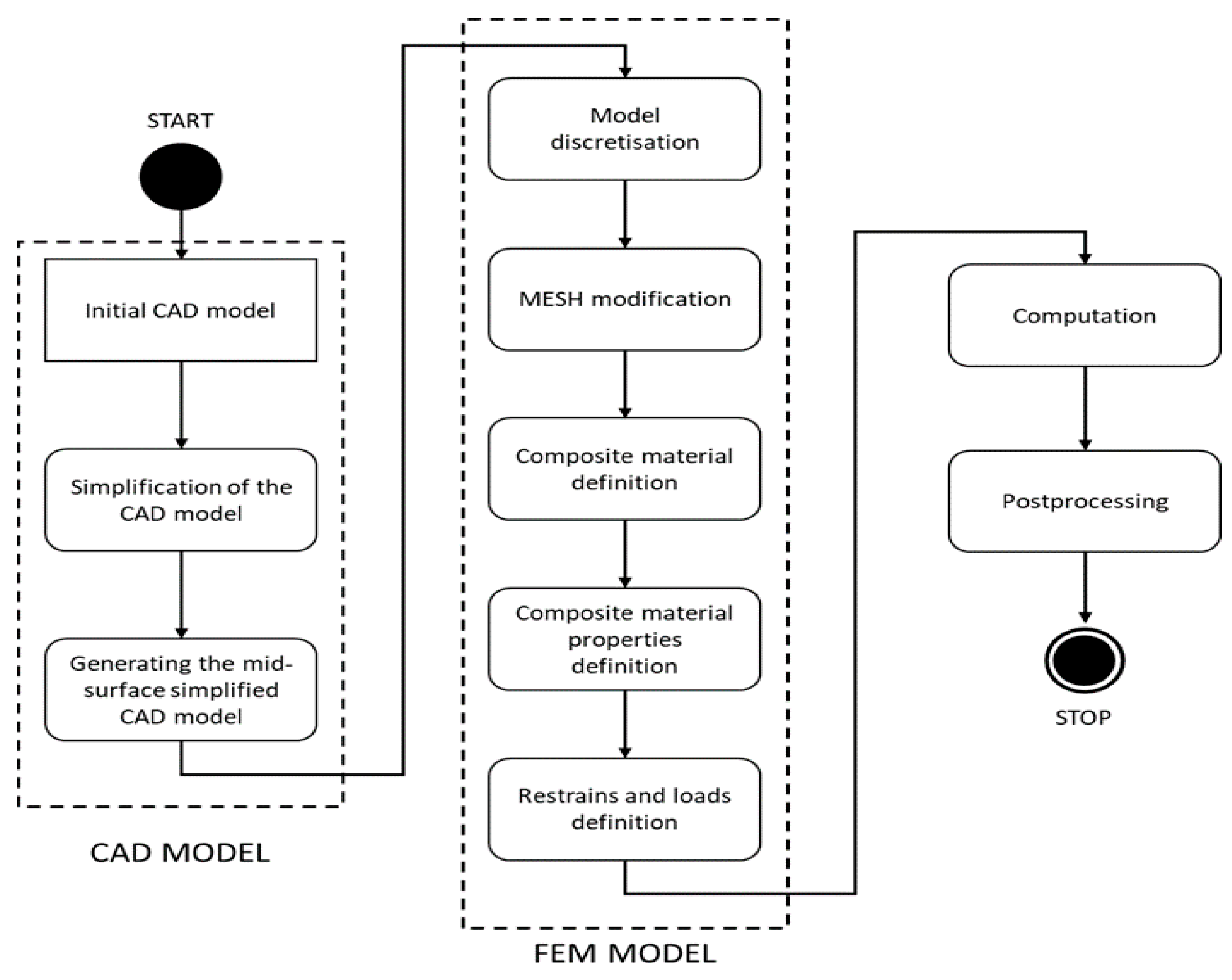
For all stages of model development, the numerical validation procedure was the same. The basic idea of the numerical validation process is presented in
Figure 8. The proposed methodology is based on three standard stages: (1) preprocessing, where we worked with a CAD model to obtain the numerical representation of the validated model; (2) computation, which in our case consists of three stages: frequencies analysis, structural analysis, and buckling analysis; (3) postprocessing, where a user can decide if the model fulfils all required assumption or need some changes and to be revalidated based on the results.
At different stages of the project development, a different approach was used to define material data. In the conceptual design, a very simplified approach is usually used—the material is defined as isotropic for analytical calculations and the calculations are to indicate the expected shape and cross-sections of the supporting structures. If FEM verification calculations are carried out at this stage, then simplified models and material data are also defined in this way. Material data were selected depending on the intended target material and many different options were explored. In preliminary design for composite elements, the preliminary internal structure of the reinforcement was selected and the material data were determined based on the general material data for the reinforcement class. Only in the next stages, and in particular during the production of the prototype, were samples made to fully identify the material data of the given composite structures; only such data give accurate results. Each subsequent stage of approximation brings the results closer to those expected in reality.
3.2. Numerical Model Preparation
The basis of Finite Element Analysis(FEA) analysis is the CAD model, and depending on the design stage, the model has different levels of detail. So, it was necessary to elaborate a process after which the input geometry for analysis will mostly be the same. This issue forced the authors to add additional steps that proceed with the central part of the study.
To unify the input geometry, the authors decided that the CAD model must be adequately prepared in the preprocessing stage. This preparation includes:
geometry simplification;
removing all unnecessary chamfers and filets as well as holes that will be smaller than the mesh size;
removing all unrelated components such as fasteners, additional equipment, etc.
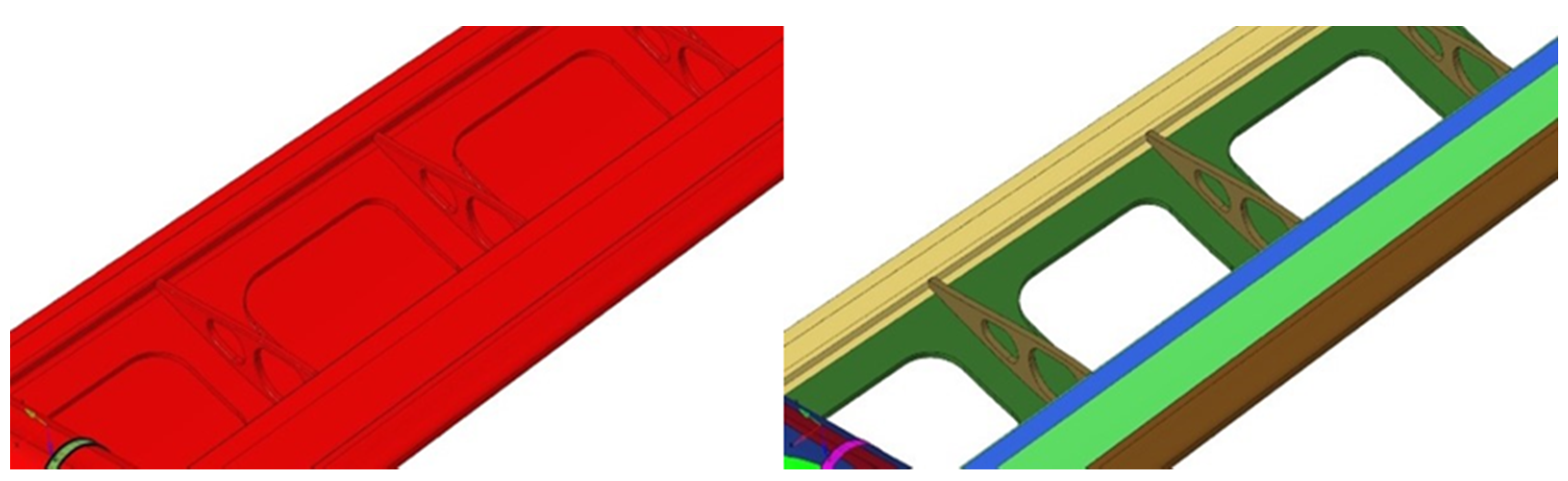
After the simplification process, the model must be divided into segments that correspond to the composite structure. An example of the simplification and segmentation process is shown in
Figure 9.
In the segmentation process, each composite structure acquires a unique color code, which allows to quickly interpret the model material structure and define the material properties in the future steps of the analysis. The final phase of the geometry preparation is the extraction of the mid-surface for each component. This process provides the consistency geometry input for the loads and constraints definition in the later stages.
In general, composite structures can be calculated using a few different approaches. In the basic strategy, the layer modelling technique is used, that using 2D or 3D finite elements, is dominant. In the presented method, the authors decided to use only 2D shell elements. This decision is since in thin-layer composites, the thickness is the smallest dimension, and the ratio to the other dimensions is quite large.
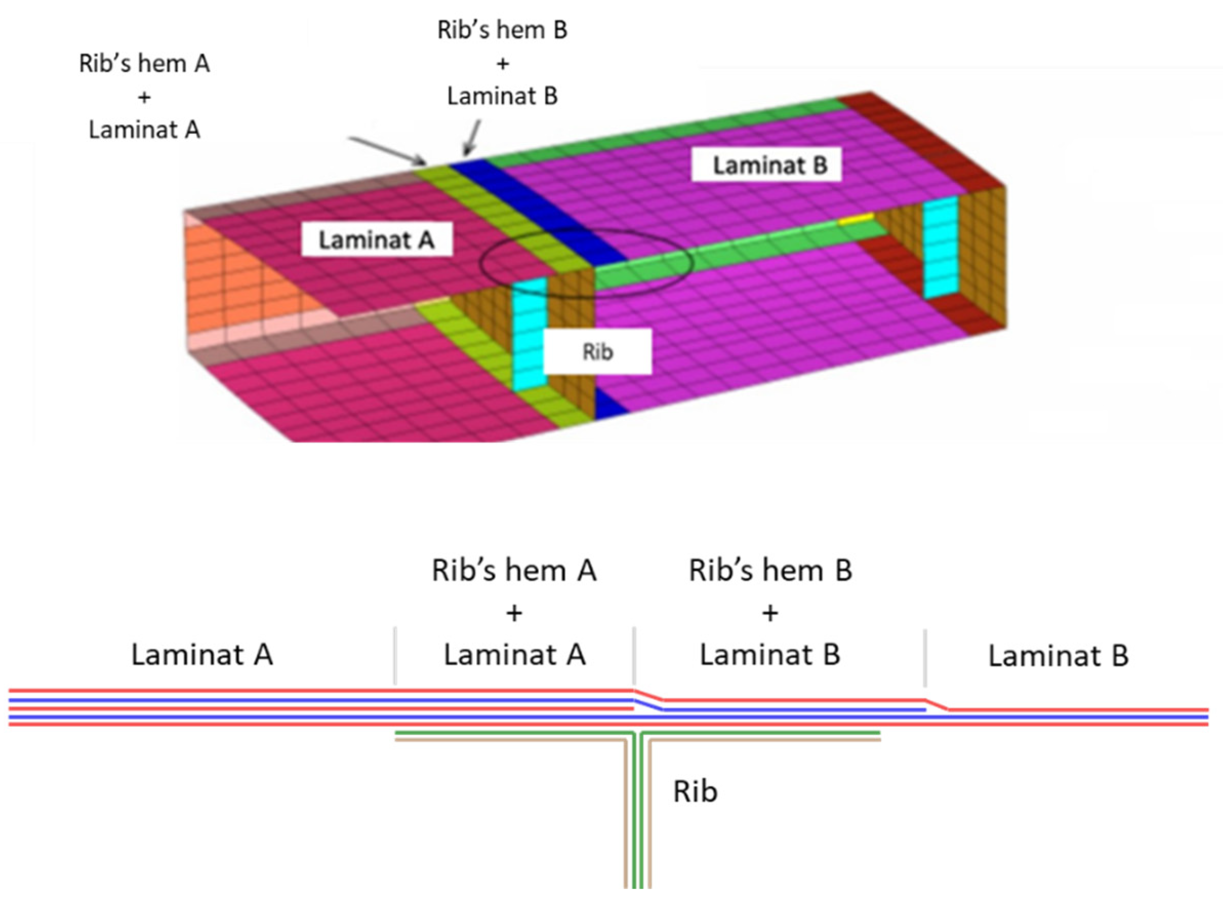
The next step in the numerical model preparation process is a simplification of contact areas, especially where ribs or other elements are joined to outer structures. In case for a perpendicular connection, the authors reduced the connection to a single component which contains layers of both base laminate and rib laminate. An example of the contact area simplification is presented in
Figure 10.
In case of a parallel connection, simple nods joining is enough and there is no need to create a new component, as in the case of perpendicular connections. After this stage, the discrete model was ready to apply loads and constraints.
3.3. Loads and Constraints Definition
Additionally, to unify the load application process, all forces and momentums were applied to the center of mass, laying on the cord line. Additionally, to discretize the continuous load, the authors decided to use loads in selected points—mostly the joints where ribs connect with a spar. The idea behind the load application is presented in
Figure 11. The values of such distributed loads are calculated from the aerodynamic forces and mass loads, based on different flight scenarios.
3.4. Computation
After the definition of the numerical model, the analysis can be computed. In the authors’ approach, computation was realized in three stages. In the first stage, the first 50 natural frequencies were calculated. Knowledge about these frequencies is vital during the aeroelastic validation of the project. In this stage, the model was computed for both no constraints and with constraints applied.
In the second stage of the computation process, the standard structural analysis was performed. Based on the results of this stage, it was possible to evaluate the overall designed structure and detect areas where some problems were expected.
The last computation stage was devoted to performing buckling analysis. This type of research allows the verification of the stiffness of components and finds some potentially problematic elements.
Based on these results, the user can decide if the project needs to be redesign, what require only some parameters values change, thanks to the generative modelling, or to approve the project for the next stage of the designing/manufacturing process.
In the next part of the paper, the authors present how the presented methodology can be used in the use case of unique aircraft design.
4. Use Case
In this part of the paper, the authors present how the developed methodology can be applied in the real case—TWIN STRATOS UAV. TWIN STRATOS is part of the UAV family and was developed as part of the LEADER project implemented by an international consortium consisting of SkyTech eLab LLC, Silesian University of Technology, Universities of Warsaw, and Norwegian Research Center. The section presents a short description of the TWIN STRATOS UAV and further steps that have been made during the design and validation process.
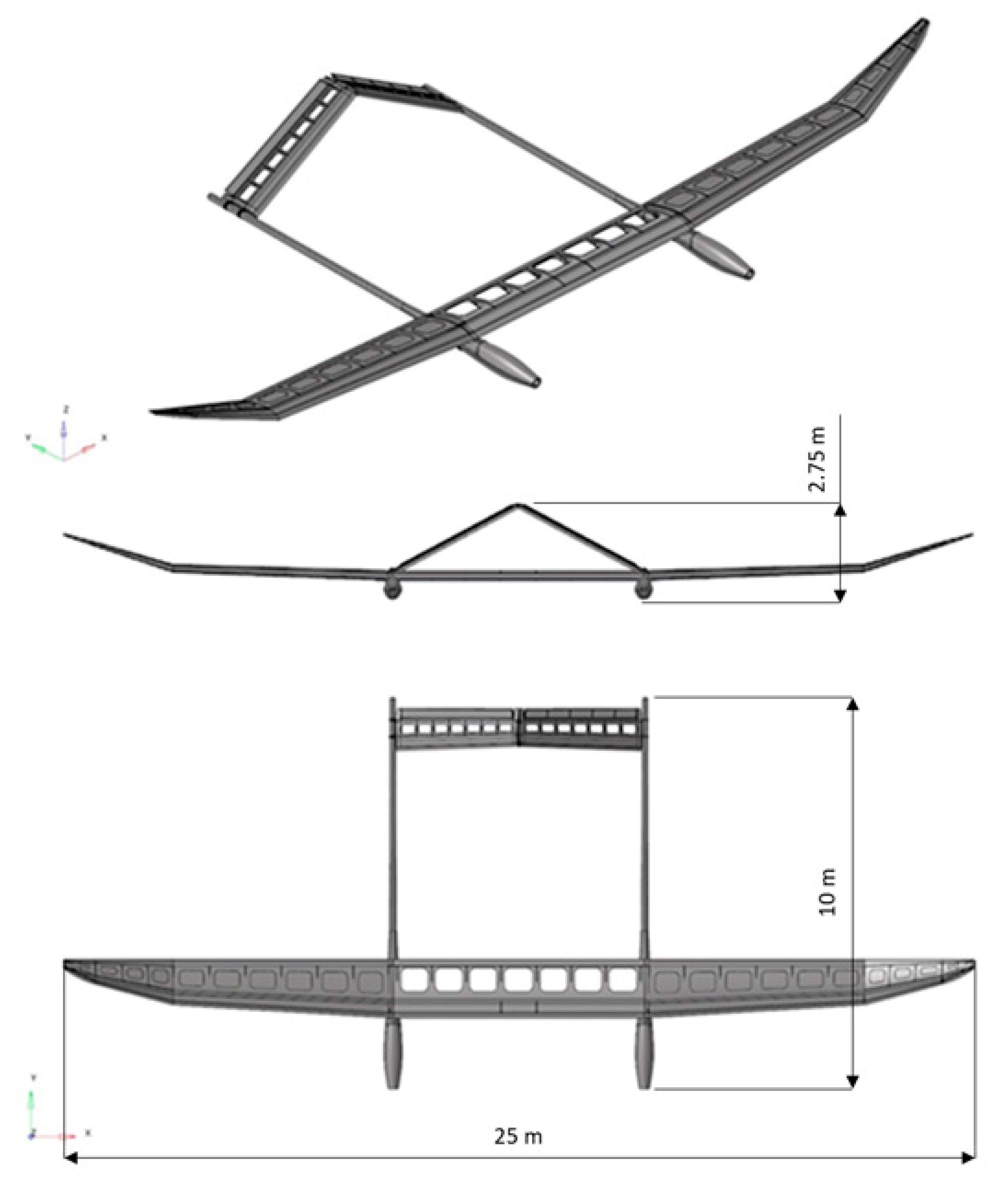
The TWIN STRATOS project is a stratospheric unmanned aerial vehicle (UAV) family project designed for high atmospheric and stratospheric measurements of air pollution. The form of designed UAV family member is shown in
Figure 12. The wingspan is 24 m with a 30 kg total payload. Thanks to the use of an electrical drive system and photovoltaic panels, the flight duration, in theory, is unlimited.
4.1. Strain, Stresses and Buckling Analysis
4.1.1. CAD Model Elaboration
Based on the project assumption, in the first step, the geometry of the UAV was designed. In this process, some load-bearing elements, i.e., spars, ribs, stinger, were intended as part of the generative model. To make this possible, the authors prepared a series of generative models for individual component types. Each model contained geometrical information about different designed elements’ shape types, control rules, parameters, etc. As a main geometrical input, airfoil curve was used. This geometrical input was used because it is relatively easy to extract this type of curve along the wing. In the case of a fuselage as the geometrical input, a cross-section profile was used. Using the generative modelling technique allows quick changes to be made in the basic load-bearing structure if it is necessary, which makes the whole process of conceptual design much more comfortable and faster in comparison to the traditional design process. The prepared CAD model for numerical validation is presented in
Figure 13.
4.1.2. Numerical Model Preparation
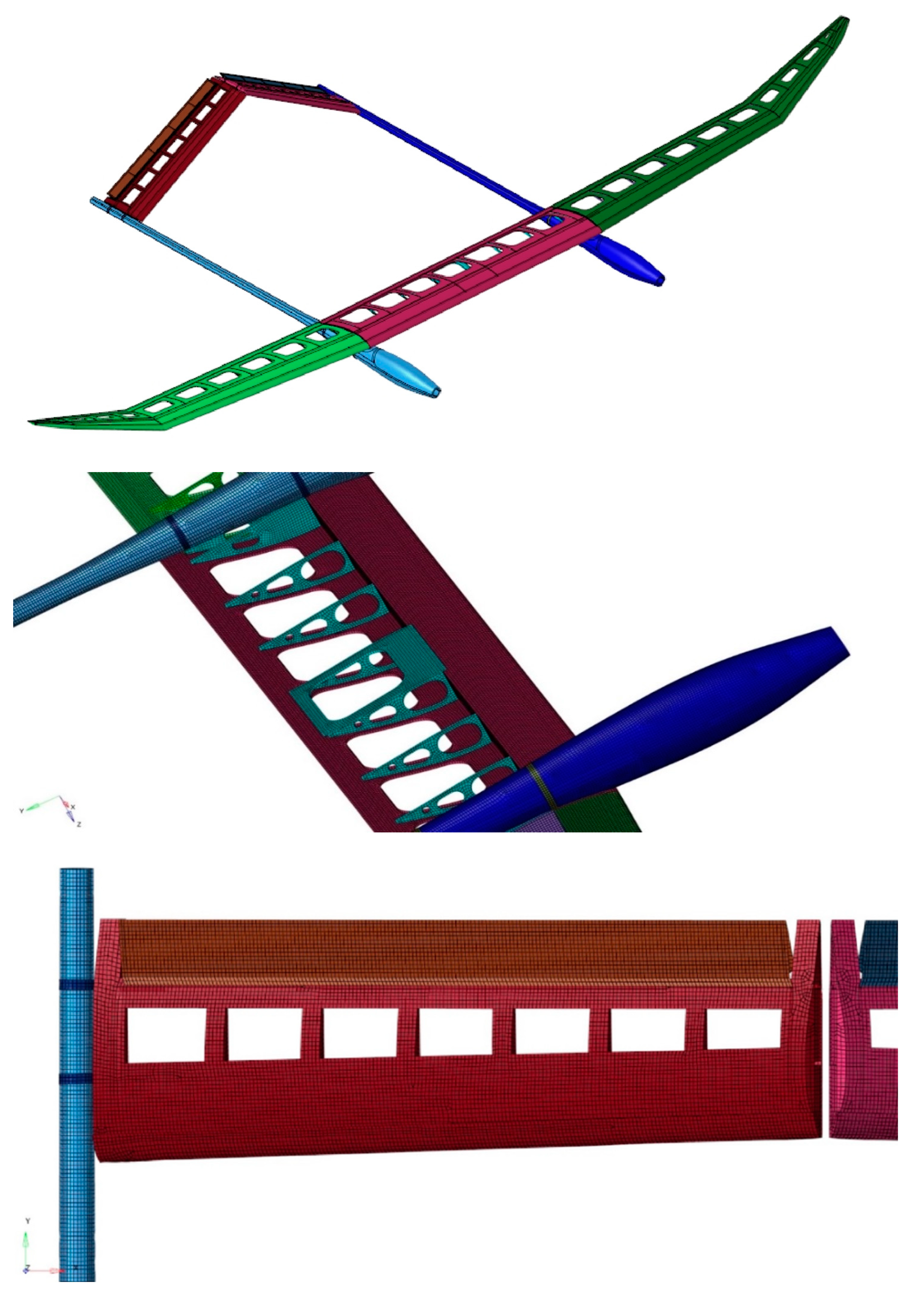
After geometry development, the phase of the numerical validation of the project must be performed. As presented in the previous section, the delivered CAD geometry must be processed to be usable for the study. In
Figure 14, general and detailed images presenting the TWIN STRATOS after the simplification and discretization process are shown. As can be seen, different components have different colors that correspond to the other composite structure, and which are related to the different material and structural properties. All preparation was related to the numerical model, the computation process, and the postprocessing of the results was conducted in Altair HyperWorks software.
4.1.3. Material Properties
In
Table 1, material properties that were used in the study definition are presented. For following approach for the calculations, general material data based on manufacturers’ data were adopted.
4.1.4. Loads and Constraints Definition
Preliminary calculations of loads were made due to the similarity with the use of software supporting glider analysis. Unfortunately, the analysis did not allow modelling the case of a double-hulled aircraft due to the different nature of the application. The better weight distribution of the two-hull system ensures that the actual loads will be lower. Load calculations were made for successive heights, flight speeds, angles of attack and flight conditions. In the final stage, a load envelope was developed for the subsequent sections of the wing. The envelope covered the maximum loads recorded in each section, although in adjacent sections they occurred in other flight conditions. In most cases, the maximum loads occur in flight at maximum flight altitudes with high speeds and gusts. Such an envelope was used in the preliminary strength calculations. At the next stages, the calculations were made based on proprietary software, considering the weight distribution system of the two-hull aircraft, and then using the XFLR5 system.
According to the presented method of load application, the authors applied properly calculated loads as well as constraints. An example of applied restraints added to fuselage mounting rings is presented in
Figure 15.
4.1.5. Obtained Results
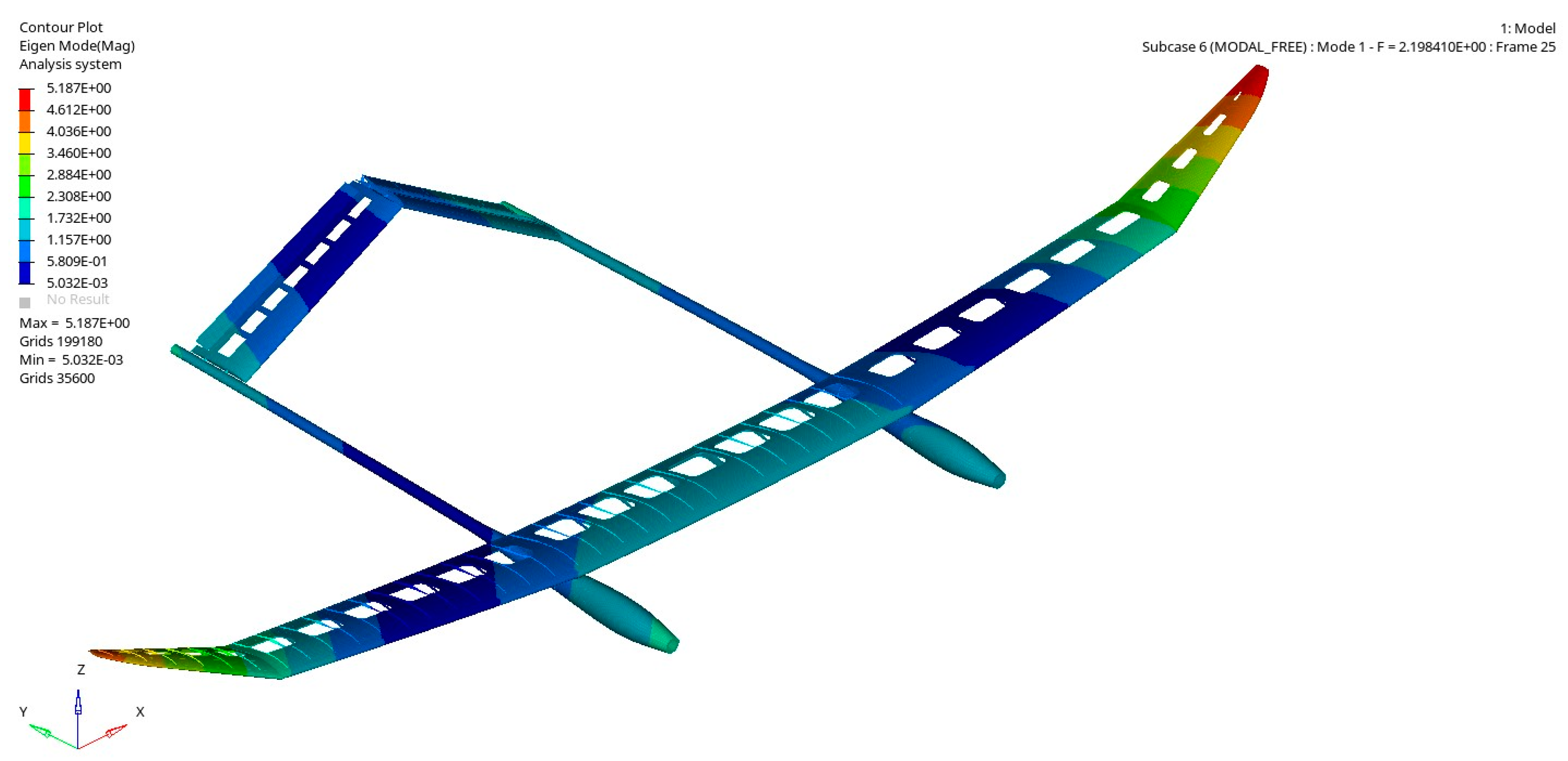
The prepared model was used to perform the computation procedure. In the first step, natural frequencies were calculated for both no constraints and with constraints. An example of the commutated natural frequency is shown in
Figure 16. In the process, the first 50 frequencies were calculated for further aeroelastic analysis.
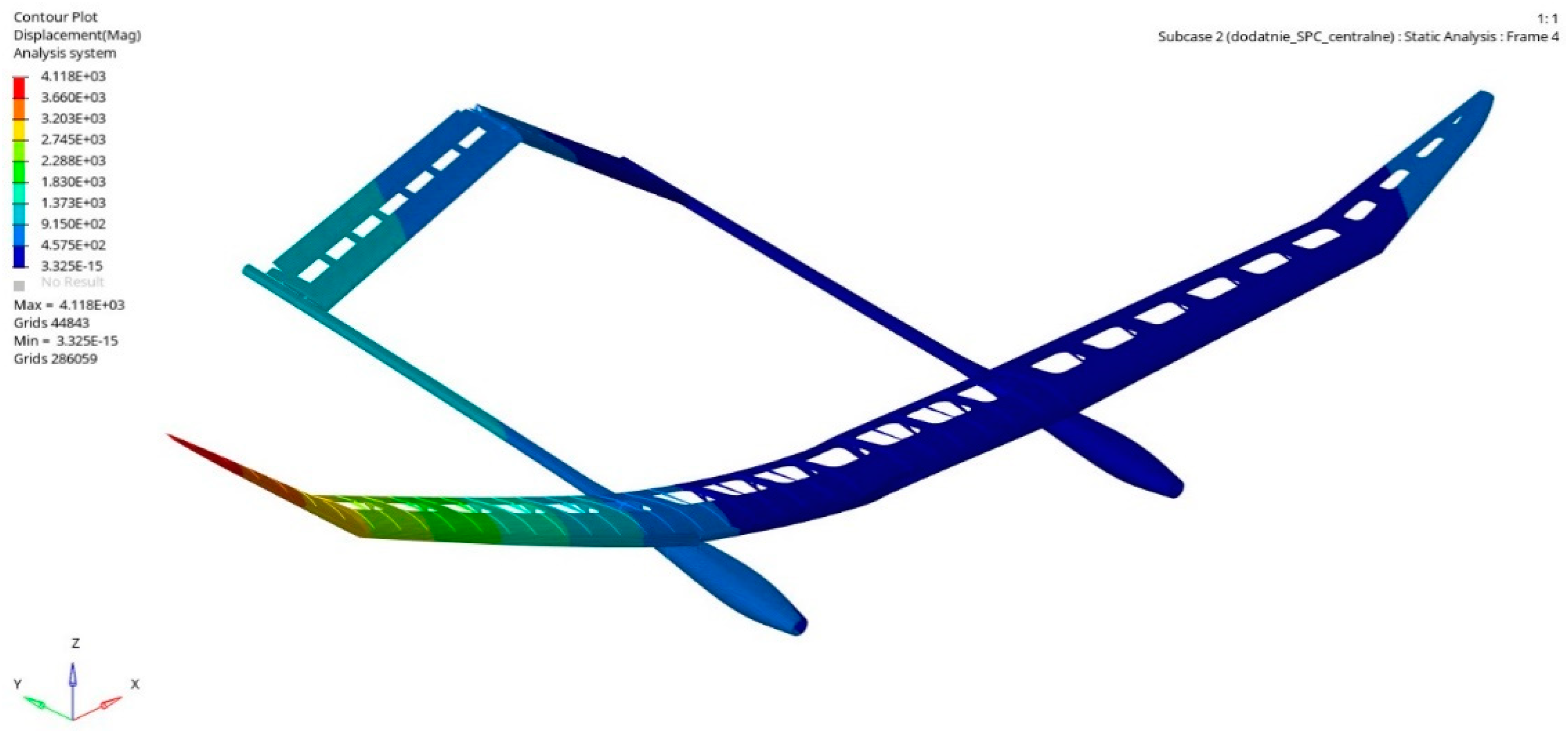
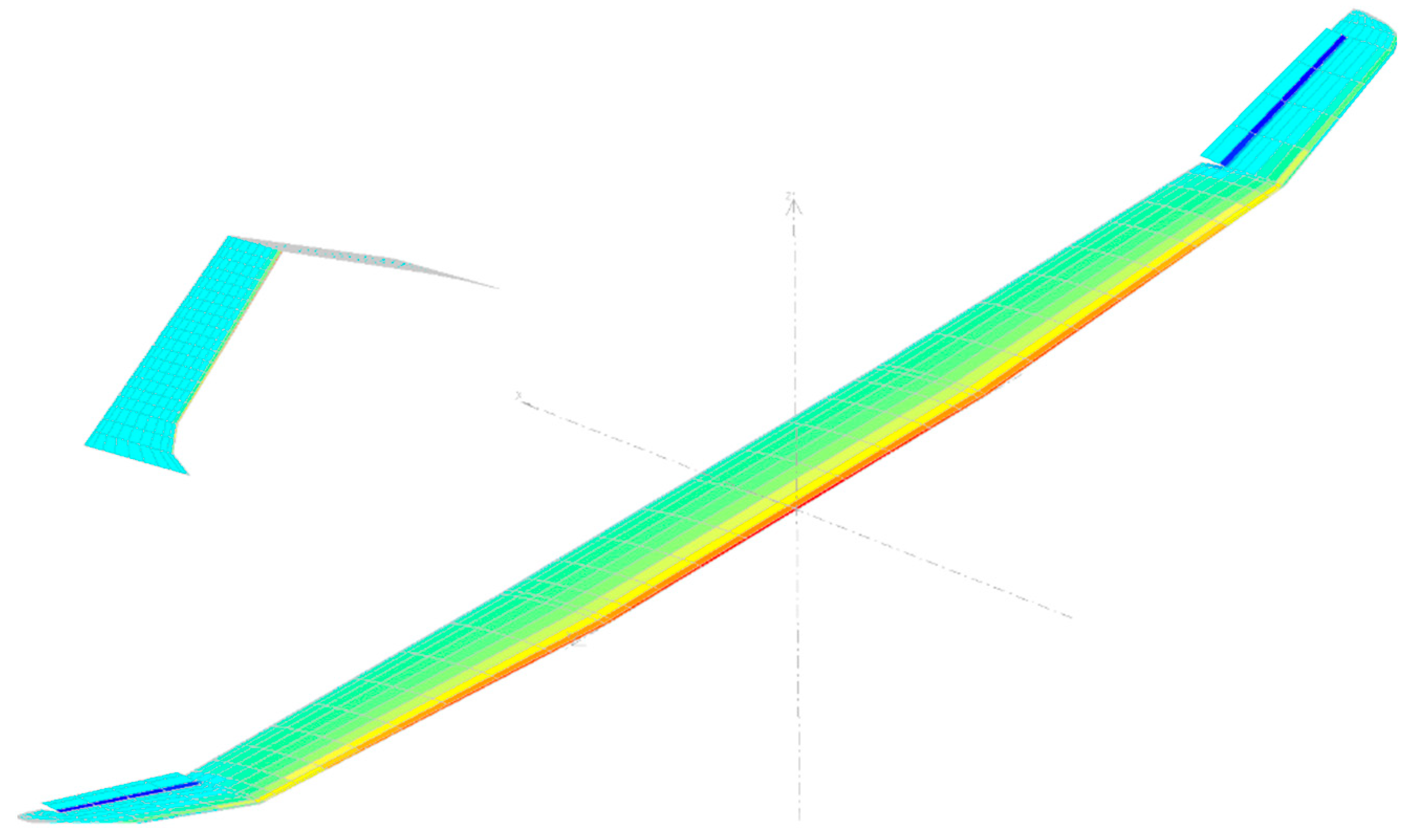
In the second step, standard structural analysis was performed. In this case, two analyses were conducted, the first one for the positive loads’ envelope, and the second for the negative loads’ envelope. As a result of this stage of the study, we obtained colored stress and displacement maps. Examples of the obtained results are presented in
Figure 17 and
Figure 18.
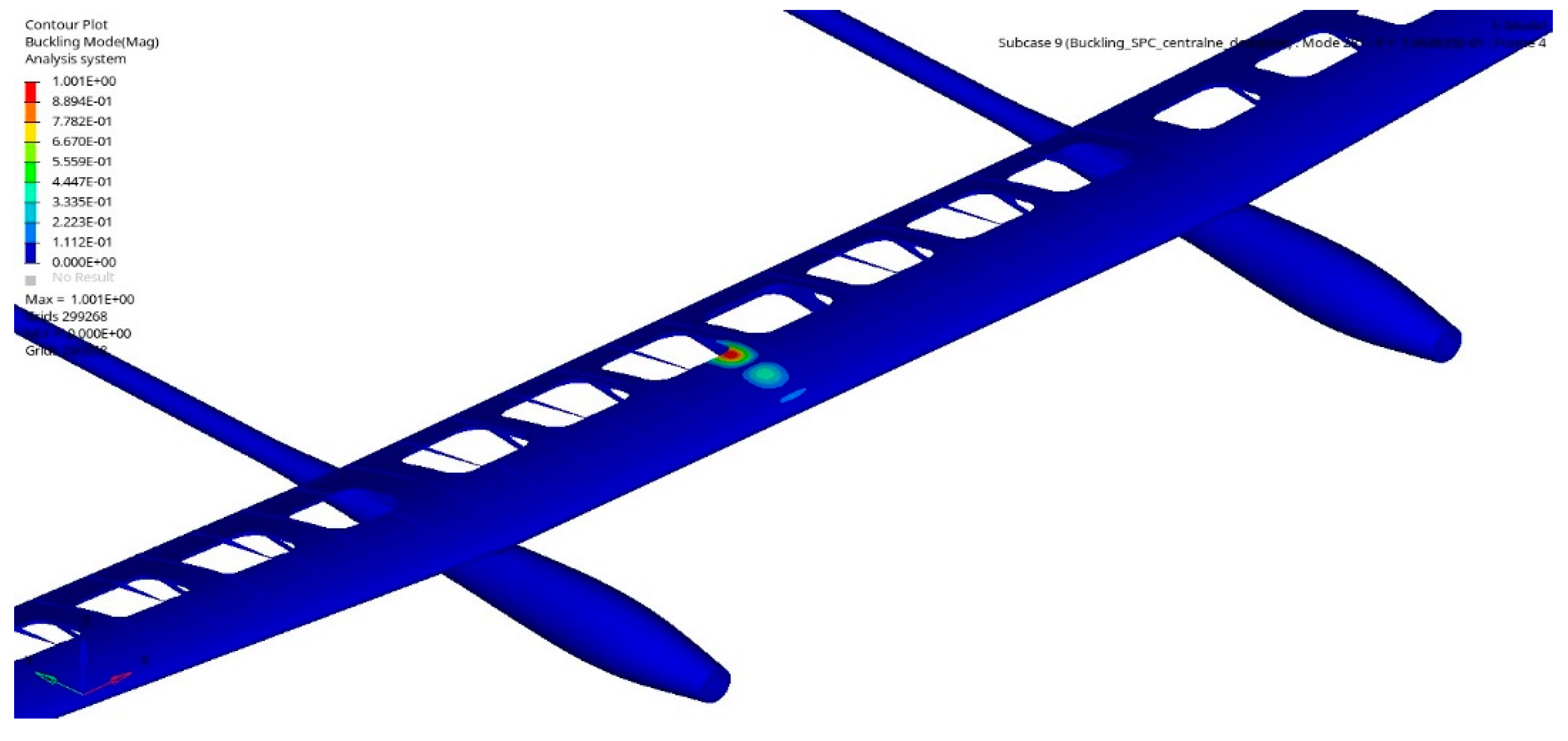
The last part of the computation process is buckling analysis used for stiffens and stability evaluation. An example of the result of this analysis is presented in
Figure 19.
Based on the performed computations, it was possible to avoid some potential issues in the design. For example, the buckling analysis showed the area that needed to be revamped, because it is possible that in this area the UAV may lose stability and cause a crash. To address this issue, the authors, using generative modelling for honeycomb structures, changed the thickness to find out the proper value to fulfil the project’s assumptions. In this case, the authors used the generative model as a tool to making models of the structure with different thickness. In the tests, the thickness of the filling layer of the sandwich structure was increased without changing the form of the filling. The study was intended to increase the viewer on the loss of stability in compressed structures. Finally, it finds out that in particularly endangered places 10 mm structure is an optimal value. The summary of the most important obtained results is presented in
Table 2.
4.2. Aeroelastic Analysis with Flutter Verification
The mid-fidelity tool ASWING was used to model aircraft aeroelasticity [
24,
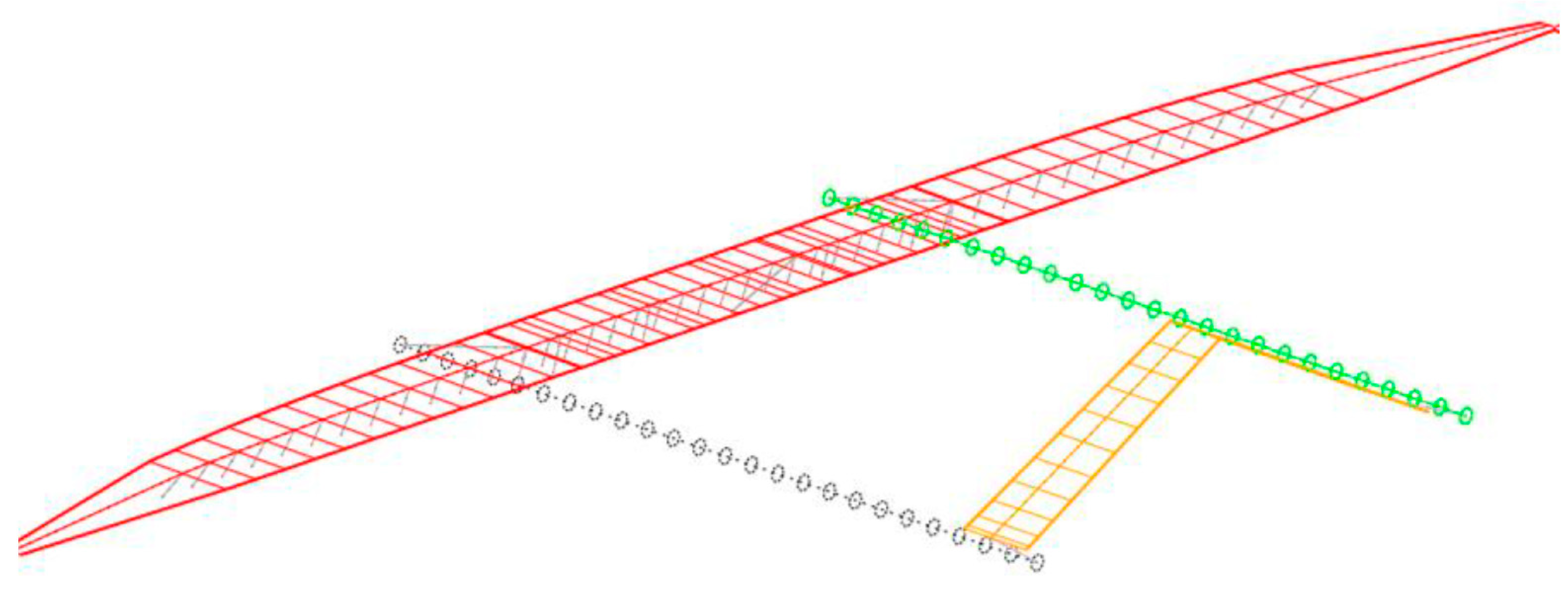
25] ASWING couples interconnected nonlinear (specifically, Bernoulli–Euler) beam models with a general extended lifting line approach. The ASWING software enables the calculation of aircraft deflections, axial strains and shear stresses, aircraft aerodynamic properties, and aircraft stability derivatives and eigenvalues based on input data, including geometric, structural, and aerodynamic parameters airfoil sections along the aircraft wing and other surfaces. During analysis, aircraft stability derivatives and eigenvalues were used because the different outputs were identified using other methods. The model used as the input to ASWING was calculated to form the parametric CAD model (
Figure 20); material data assumed for analysis and load distribution were identified using XFLR5 [
26]. The data were integrated into excel file and subsequently transferred to a proper format which was used as the input to ASWING (
Figure 21).
The flutter speed and actual flutter frequency are indicated by one of the eigenvalues crossing over from left to right of the imaginary axis. Flight-dynamic instabilities (e.g., spiral mode) will also have eigenvalues on the right side of the imaginary axis, but these will typically be at a near-zero frequency and will have completely different eigenmodes.
The results of the initial analyses indicated the risk of flutter at a speed of 20 m/s, (
Figure 22), which is a speed exceeding the operating speed. A sensitivity analysis was performed during the flutter analysis. The influence of the position of the wing mass was investigated. The first simplified analysis assumed that the solar panels are positioned proportionally to the wing area. The model was then refined by adding mass points symbolizing solar panels at a distance of 0.4 of the wing chord from the leading edge. In the last iteration of calculations, the influence of shifting the mass of solar panels by 80 (mm) towards the leading edge was investigated. Sensitivity analysis showed the possibility of turning the critical flutter velocity in these cases to 25 and 35 m/s, respectively.
4.3. Comparative Analysis of Morphic Control
During the study, the main problem that should be solved is the considered design’s aerodynamic performance. The airplane structure was reconstructed in XFLR5 software, as shown in
Figure 23. The tests were similar to the aeroelasticity analyses (
Figure 21) and carried out for various configurations of control systems [
27].
The main aircraft wing was divided into several sections with differing chords and dihedrals. Different versions of roll control elements were taken into account. The following analysis compared three control options—classical with ailerons, tail control, wingtip twist morphing (
Figure 24).
Figure 24 shows the distribution of the lifting force coefficient (Cl) in the given wing section as a function of the main wingspan and the tail wingspan measured from the symmetry plane for the roll operation for different angle of attack (ACA) (0°; 5,5°; 10°).
The computational simulation results confirmed the legitimacy of applying innovative solutions, both integrated in the tail and morphic wingtips. In both cases, the new control configurations became even 10% more efficient in the entire range of attack angles [
27].
5. Conclusions
The design process is iterative, and the number of approximations in the case of a complex UAV object can be significant. Nowadays, CAD systems are commonly used to model the geometric form. In each of these approximations, it is necessary to generate a new geometric model, which is laborious and may lead to errors and inconsistencies. Automating the generation of a geometric model in the CAD system using generative modelling can significantly accelerate this process. Such generative models can be used both in the case of iterative improvement of the structure by designers and the application of optimization algorithms. The article describes improving a very unusual HALE UAV structure, where subsequent analyses are usually preceded by a labor-intensive rebuilding of the geometric model. Such an operation can be supported by using a generative model in the form of structured modules that enable structural modifications which are not understood in most low-fidelity verification methods of a parametric mesh but are in a multielement engineering model in the CAD system. The proposed solution does not eliminate the methods and models mentioned above—it perfectly complements them, as it allows for remodeling of a complex engineering structure and several engineering verifications that go far beyond general verification methods. In this way, the FEM analysis is performed not only on the general support structure but also on a highly verified design, including technological, assembly and general engineering relations.
The most important contributions of the paper are:
A methodology for automating the design of ultralight and highly flexible aircraft structures with the use of generative modeling.
Proposing and verifying the form of generative models for selected fragments of the structure, especially wings.
Integration of the use of generative models for iterative improvement of structures using low- and middle-fidelity methods of numerical verification.
In future works, it is necessary to improve the design processes with the use of generative modelling, and in particular for further automation and integration with numerical verification methods and tools. Work will be carried out to extend the range of generative models to include less typical design solutions. Depending on needs, the generative models developed as part of the research will also be transferred to other CAD tools. Improvements of the design procedures for unusual classes of flying objects, such as HALE UAVs, are also required.


