1. Introduction
Eigenvalue analyses to predict the stability of physical systems exposed to nonconservative forces is a current topic in engineering applications. The eigenvalues of such systems exhibit behavior that depends on the amplitudes of the nonconservative forces acting on them. These dependencies lead to effects such as semisimple and non-semisimple 1:1 resonance of the system [
1]. This phenomenon is also known as Hamiltonian–Hopf bifurcation [
2] or Krein Kollision [
3] and, in mechanical engineering terminology, known as a mode coupling, causing flutter-type instability in mechanical systems.
This phenomenon is well-known in various mechanical applications where nonconservative forces play significant roles, for example, in rotary machinery with viscous damping in the shaft bearings [
4], in aerodynamic systems exposed to wind flow [
5], in hydrodynamic systems loaded with hydrodynamic forces [
6], and in disc brake systems where friction forces are acting between a pad and a disc [
7].
Nonconservative friction force into a brake system produces an undesirable phenomenon known as brake squeal. Brake squeal is a complex problem caused by the nonconservative nature of friction force, which desymmetrizes the coefficient matrixes of mechanical systems [
8]. Several different mechanisms causing brake squeal have been studied in the past decades [
9,
10], but the most significant contributor to brake squeal was identified to be mode coupling.
The unstable behavior of mechanical systems can be caused by dissipation-induced instability, which was previously discussed in the work of Hoffmann et al. [
11] in the case of brake systems. Dissipation-induced instability of disc brakes was later discussed in [
12] through finite element (FE) analyses on a complex brake system. The authors reported changes in coalescence patterns when two coalescing modes are differently damped by modification of the damping matrix. Damping values were, however, artificially chosen without evidence, so the question remains about the significance of this effect in real systems. In general, the destabilization effect was first observed by Smith [
13] when studying the stability of elastic rotors exposed to friction in bearings.
Vibration energy in brake systems is mainly dissipated due to material damping in system components and friction-induced damping between a pad and a disc [
14]. Regarding the squeal prediction procedures, the FE method and complex eigenvalue analysis (CEVA) are commonly used to predict unstable vibration modes of a system [
15].
Several research studies reported that the simplification of damping in the form of Rayleigh damping can be acceptable for conservative systems, but in nonconservative circulatory systems, like disc brakes, stability is produced not only by the magnitude of damping but also by damping distribution over the structure. Since the friction material (FM) and the disc have damping that is an order of magnitude different [
16,
17] and system damping is thus far from Raleigh, it is appropriate to expect dissipation-induced instability in such systems. Masoomi et al. [
18] studied the modification of damping properties of the FM by adding thermoplastic elastomers into a FM composition. The possibility of changing the damping properties of the FM appears to be a method to control dissipation-induced instability.
In FE models, system stability depends not only on the magnitude of damping but also on the structure of the damping coefficient matrix. Hagedorn et al. [
19] thoroughly demonstrated, on simplified examples, the influence of the damping matrix structure on disc brake and paper calender system stability. Material-dependent damping optimization of the full industrial FE model of disc brakes is well-documented in a book [
20]. However, the model does not consist of a physically reasonable damping factor for the FM; thus, the effect of dissipation-induced instability due to different FMs and disc damping cannot be fully assessed from the study.
Despite the capabilities of modern FE tools to model viscous damping in CEVA, the damping is still not commonly included in industrial computational models for squeal prediction. This may be mainly due to two factors: The first is deliberately neglecting dissipation-induced instability by anticipating purely stabilizing damping, so that undamped models appear to be on the safe side of the instability prediction. This may stem from the lack of studies that objectively quantify the effect of damping on the dynamic instability of disc brakes. The second reason is the complicated quantification and estimation of damping properties of given mechanical systems, which can be seen from a variety of measured data in various studies [
16,
21,
22,
23,
24]. Some uncertain guesses are required to set the proper damping properties of computational models. Systems such as disc brake exhibit very close eigenfrequencies, and proper system identification tools for damping estimation should be chosen [
25].
Based on the above information, the basic questions that we aimed to answer were:
Can material-dependent (nonproportional) damping have a significant influence on the stability of specific disc brake structures?
Can material-dependent damping be directly applied to computational finite element models (FEMs) to streamline the instability prediction process?
These questions were answered by numerical analyses of damping destabilization effects on simplified as well as the complex FE models of a disc brake. The modal properties of the FE model were experimentally verified and damping properties of the disc structure were estimated from the experiment.
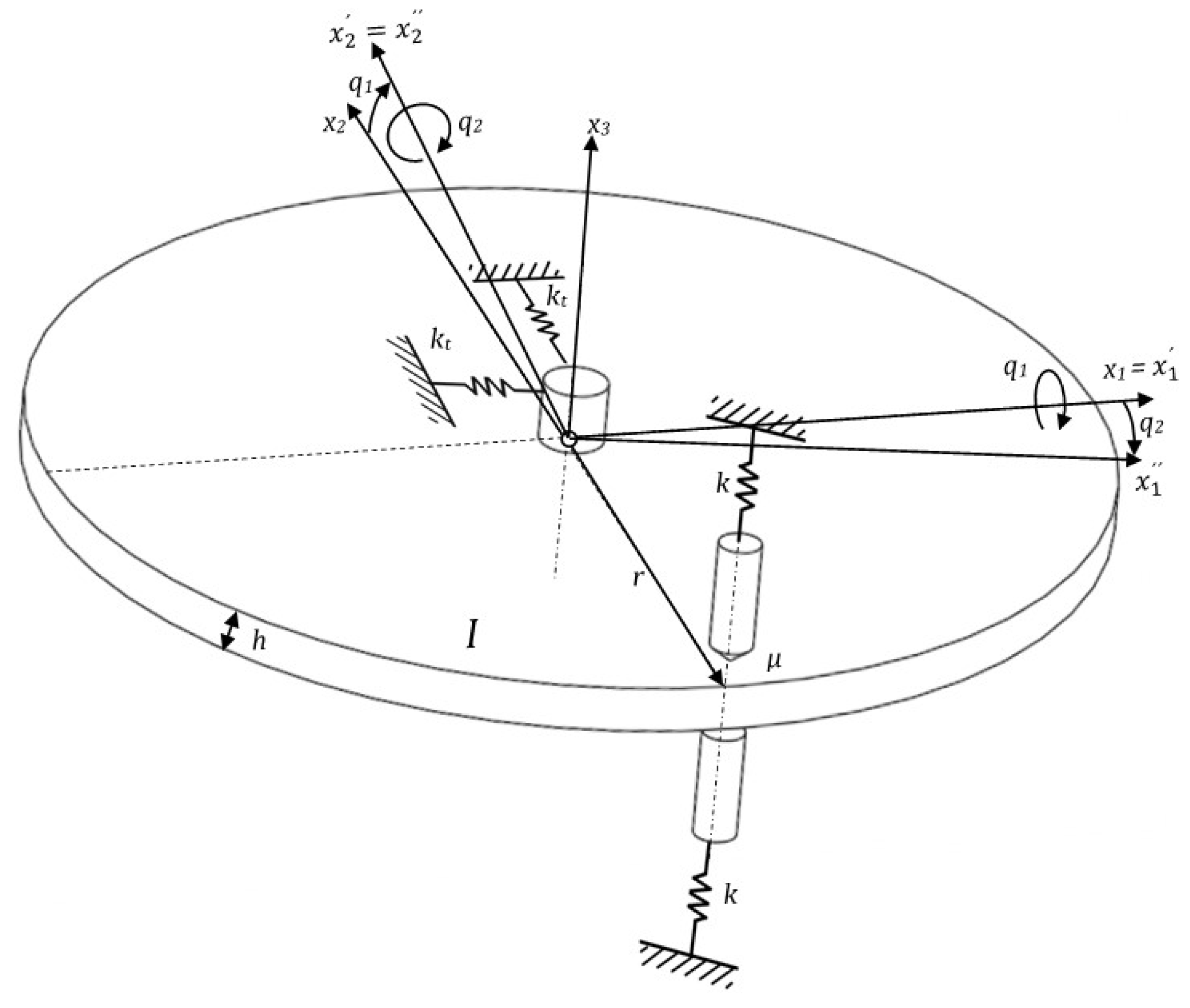
3. Pad-on-Disc System Description
A complex model of a disc brake was considered in the form of the pad-on-disc system, shown in
Figure 3a. The physical principle of the operation of the experimental device is described below.
FM 8 was pressed against the rotating discs 9 through the thin plate 7. Due to the rotation of the brake disc 9 and the friction forces F between the brake disc 9 and FM 8, FM 8 tilted, as shown in
Figure 3b. From the point of view of arrangement dynamics, nonconservative frictional forces cause dynamic instability and lead to brake squeal. The basic dimensions of the system components are listed in
Table 2.
3.1. Analyses of Brake Squeal on Simplified Experimental Brake Model
For the analyses of the modal content of the given system, frequency response function (FRF) measurement was performed on free and mounted and loaded discs. The measurements revealed possible modes as candidates for mode coupling leading to squeal. The measurements were recorded by an accelerometer sensor placed on the disc structure and the modal hammer (
Figure 4) equipped with a hammer tip with a steel insert (hard), permitting the energy content of the force impulse to excite the structure of the disc within the range of the desired frequencies. The maximum sampling time interval for FRF measurements was 5 s and the acceleration frequency range of interest was 1–10 kHz. The sampling frequency was 102.4 kS/s.
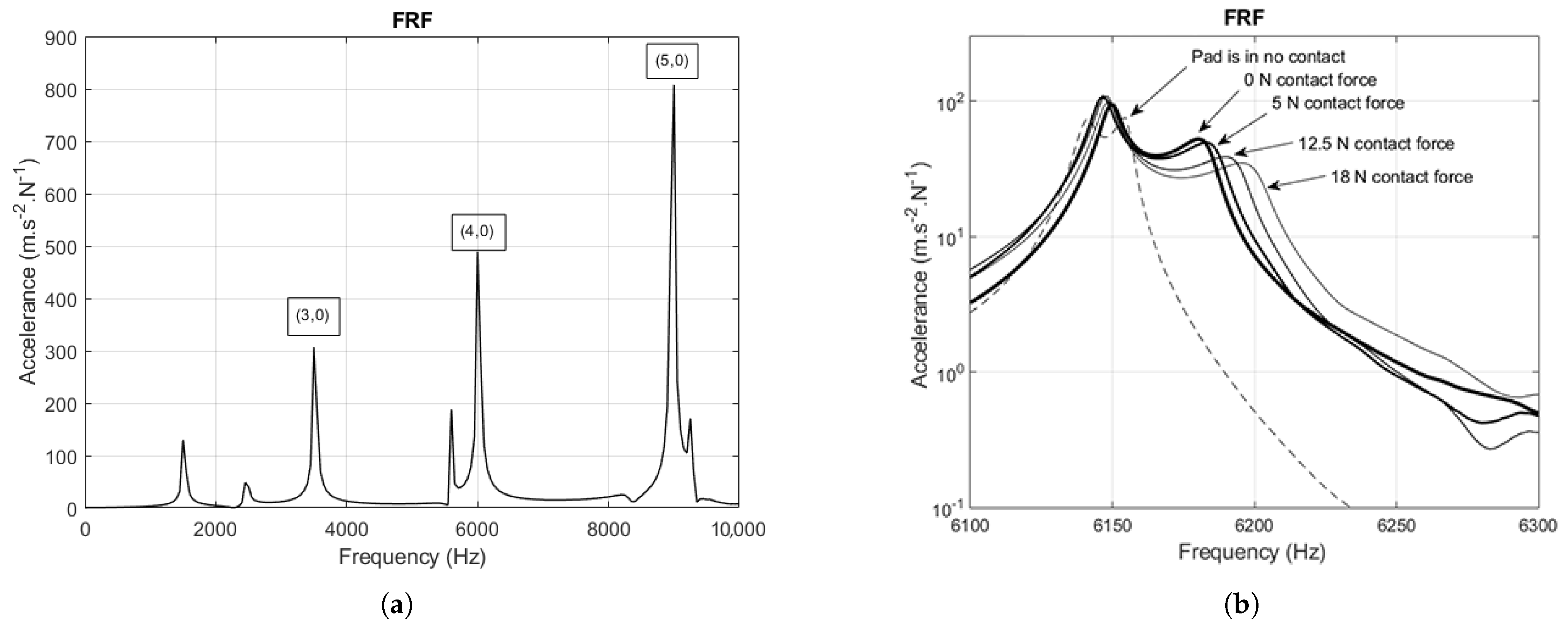
Performing fast Fourier transform (FFT) on multiple measured signals, multiple FRFs were obtained from the time signals and their averaged value for the free disc is shown in
Figure 5a. The numbers in brackets (d,c) represent the number of nodal diameters and the number of nodal circles of a given mode. Nodal diameter (d), also called cyclic symmetry mode number, is the number of waves, or the number of diameters in the structure, along which the displacements are zero. Nodal circles number (c) is the number of circles in the structure along which the displacements are zero. Three bending modes of three, four, and five nodal diameters were identified using experimental modal analysis (EMA).
Figure 5b shows details of the FRF for the attached and loaded disc around a couple of (4,0) modes, which are considered the most prone to coupling. Comparing
Figure 5a,b, the natural frequency of the (4,0) disc-bending mode increases when the disc is attached to the hub. This effect is due to the stiffening by the disc to the hub attachment. A couple of natural frequencies also slightly move away from each other due to the lack of an ideal axisymmetry of the disc–hub attachment. The frequency shifting is visible when the pad comes into contact with the disc. The pad having higher damping brings additional damping to the system. We concluded from the widening of the FRF, that the tips correspond to natural frequencies of the system. Different damping of neighboring modes due to pad contact was identified at this point.
The characteristic squeal frequency of the studied system occurred in the region of 5800 Hz–6000 Hz, depending on physical conditions like temperature, contact pressure distribution between the FM and the disc, as well as fiction intensity. A typical measurement of squeal frequency, captured using two accelerometer sensors (
Figure 6a) placed on a slowly rotating disc structure, is shown in
Figure 6b.
3.2. Mathematical Description of Pad-on-Disc System
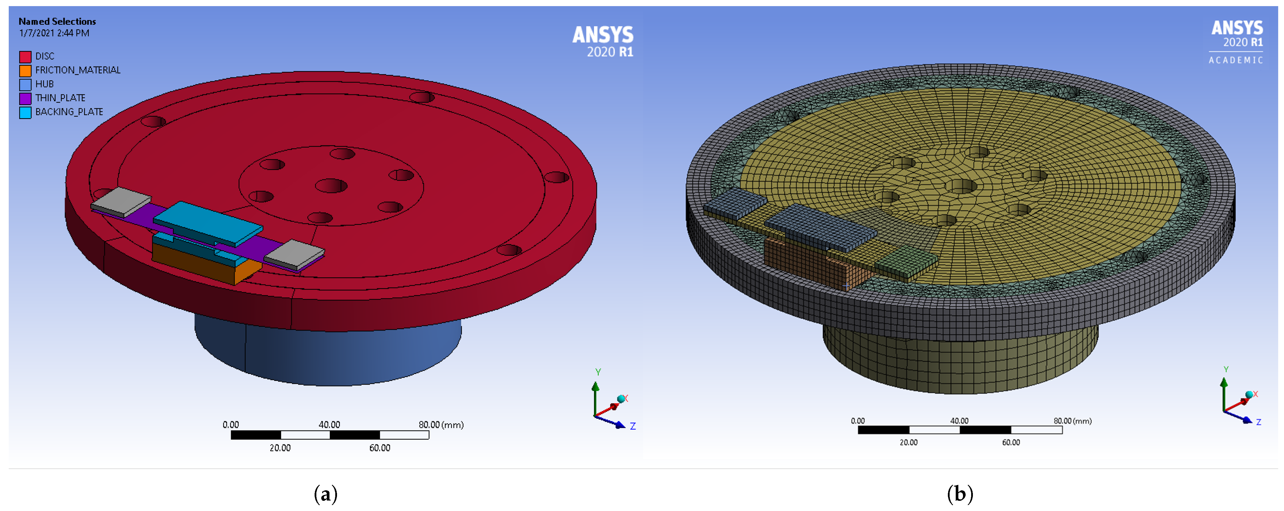
Since experimental analyses of structural damping impact on squeal are complicated and beyond the scope of this study, numerical calculations of brake squeal were adopted. The finite element method (FEM) was used to define a mathematical model of a given physical problem. FEM discretization results in a system of equations of motion with constant coefficient matrices. System stability can be studied using a solution to the general eigenvalue problem in the same way as for the simple 2 DoF system above.
The geometry of the system is shown in
Figure 7a and its FEM representation in
Figure 7b. All calculations were realized in ANSYS software. Mesh convergency analysis was performed for several mesh density configurations. The model counting 184,255 nodes and 72,520 elements to solve 545,466 equations was chosen. In comparison with a significantly more complex model counting 580,754 nodes, 146,351 elements to solve 1,729,380 equations, the model exhibits a difference of 0.1% in the imaginary part of the calculated eigenvalue (damped eigenfrequency) of the (4,0) mode and 4.8% difference in the calculated real part of a given eigenvalue (stability), with 8.4 times less CPU time needed for the solution. The FE model was defined and its modal properties were tuned following the experimental modal analyses (EMAs) on a physical model. The numerical value of the damping ratio
of the disc composed of structural steal was determined from FRF measurements for a couple of potentially unstable (4,0) modes. In ANSYS FEM code, the material-dependent damping can be modeled directly through the damping ratio or can be represented by Rayleigh damping factors, the latter of which we applied. Rayleigh damping factors
and
applied into the FE material model were determined from the equations
Under the assumption that the single components are proportionally damped and their damping ratios
of the
ith and
th modes are known, for a couple of two modes and their corresponding eigenfrequencies, two equations of two unknown factors
and
can be obtained from (
8). In the case of a symmetric disc structure, the studied couple of eigenfrequencies, related to the unstable (4,0) mode shape, are assumed to be
and their damping ratios
. In this case, unknown coefficients are calculated satisfying Equations (
8) and (
9) as
and
.
The damping ratio value for nonasbestos organic-type FM containing novolac resin as a binder and various ingredients including metallic fillers can vary in composition from 2% to 5% [
18]. The damping ratios of the remaining materials in the model were considered to be the same as for the disc component.
Table 3 lists all used material parameters.
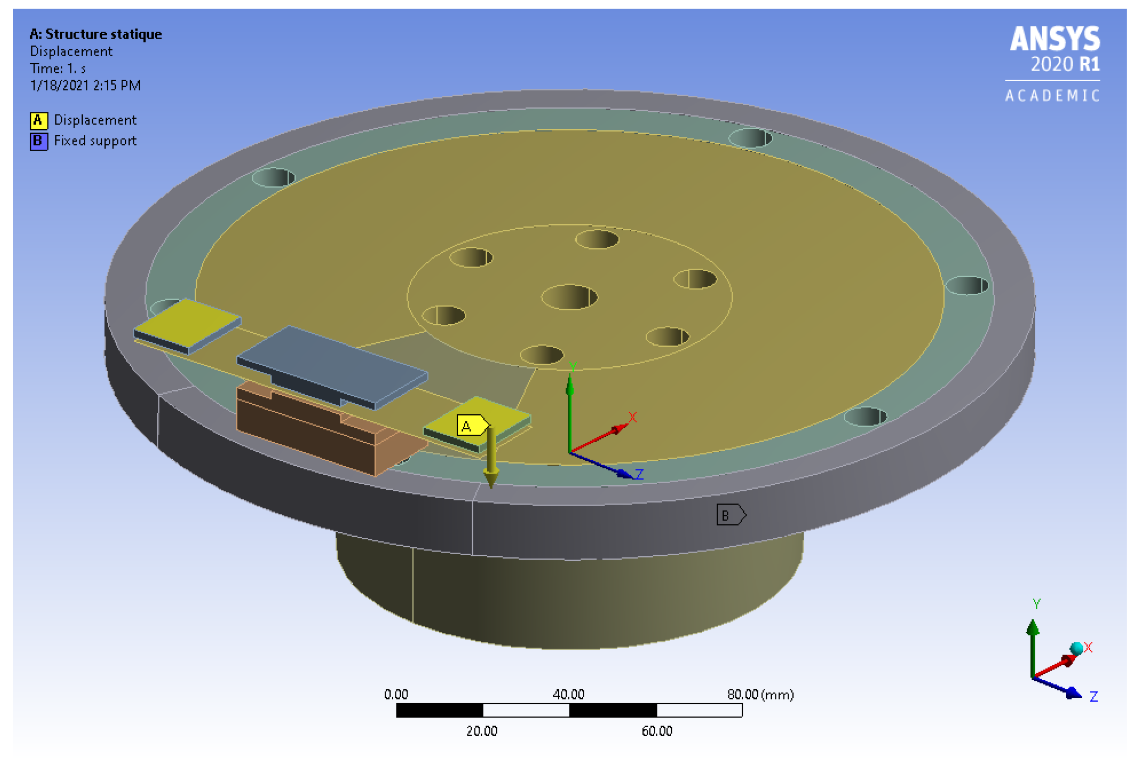
Using FE approximation of a given continuous physical system, the behavior of the system around its equilibrium position can be described by a finite set of differential equations with time-independent coefficient matrices. The static equilibrium position was achieved by prestressing nonlinear static analysis. Loading of the system was achieved by the boundary conditions defined in
Figure 8. The bottom area of the hub was fixed, while on the square yellow areas of the thin plate, displacement of 8 × 10
mm, corresponding to the reaction force of 200 N, was applied. After the equilibrium position was achieved, the pseudo rotation of the disc using the ANSYS CMROTATE command was applied in a further step of the analysis. This command sets the constant rotational velocity on the nodes of the disc element component, despite any deformation at the nodes. This feature is primarily used for generating sliding contact at frictional contact interfaces in brake-squeal analysis. Due to the sliding contact, the asymmetric coefficient matrices, in the linear differential equations set (
10), are obtained.
The terms and represent the nonconservative friction forces. The matrices and are nonsymmetric and smoothly depend on friction parameter . Symmetric positively definite matrices with respect to represent a system structural damping with respect to stiffness. The matrix is modeled nonproportionally to the and matrices due to the definition of different material damping for FM and the rest of the assembly. Gyroscopic effects were neglected in this study.
For further analyses of the system stability, complex eigenvalues
and corresponding complex displacement eigenvectors
of the original system (
10) were obtained by solving the eigenvalue problem (
11) and transformation of the complex eigenvector
from modal into generalized coordinates (
13)
The modal
and the spectral
matrixes were obtained by solving the generalized eigenvalue problem
3.3. Numerical Verification of the Proposed FE Model
The FE model was verified by a set of experimentally obtained FRF data. A couple of (4,0) disc-bending-mode frequencies were compared.
Table 4 summarizes the comparison of couples of eigenfrequencies
,
for different boundary conditions: (1) free disc, (2) attached disc, and (3) attached disc with the pad in contact. Errors
and
range from 0.3% to 5.8%.
According to the FE calculations, the system exhibited different damping ratios and for a couple of bending modes when the pad is in contact with the disc (case No. 3).
This effect can be qualitatively verified from the experimental data shown in
Figure 5b, where two neighboring eigenfrequencies exhibit different damping when the pad is in contact with the disc.
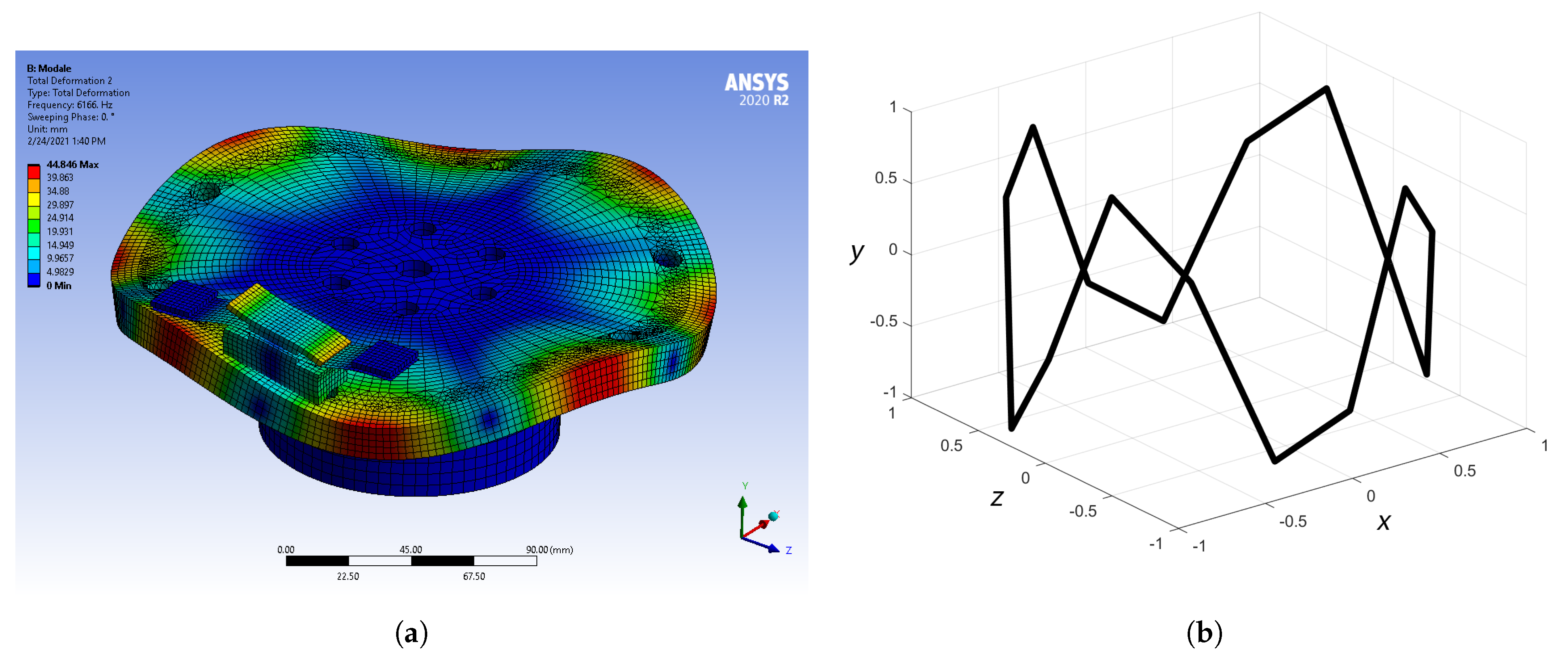
Figure 9 shows a qualitative comparison of experimentally (
Figure 9a) and numerically (
Figure 9b) obtained mode shapes corresponding to the (4,0) bending mode of disc for the No. 3 boundary conditions. The experimental mode shape was reconstructed from the set of FRFs by EMA.
3.4. Results
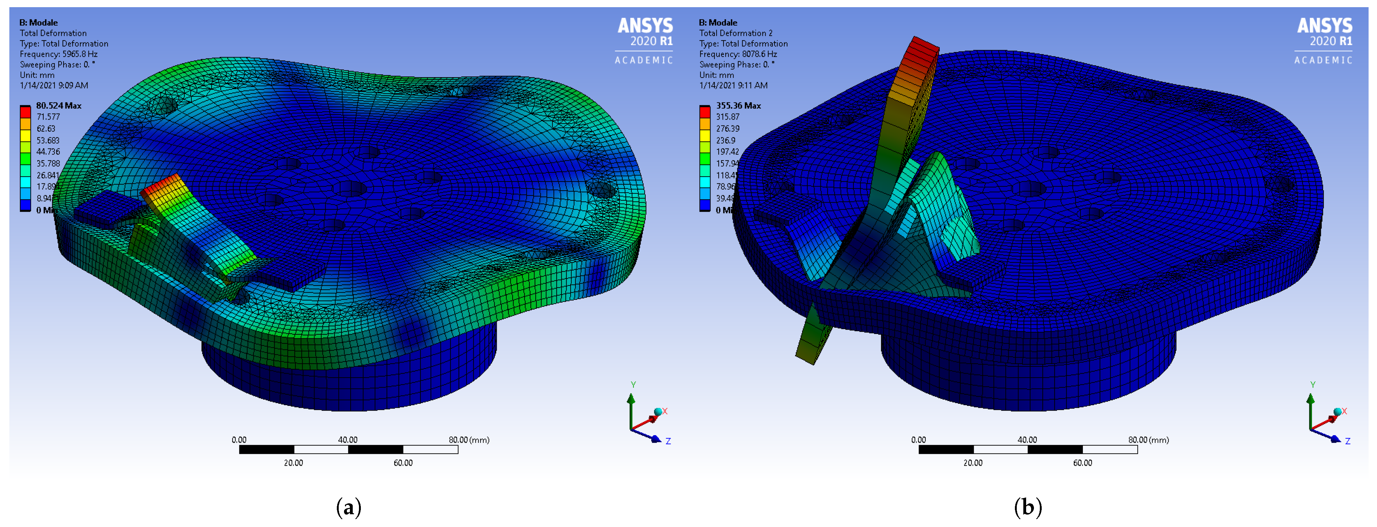
From the set of calculated eigenvalues corresponding to the region of interest 0–10 kHz and the default material properties, two unstable modes characterized by the positive real part of their eigenvalues were identified, as shown in
Figure 10.
Comparing the mode shape in
Figure 9a, representing the calculated (4,0) disc-bending mode, with the calculated unstable mode shape in
Figure 10a, we concluded that two (4,0) modes coalesce at the unstable eigenfrequency of 5966 Hz. This frequency is close to the measured squeal frequency from
Figure 6b. Since there was no other pair of modes in the vicinity of the measured squeal frequency, the unstable mode was predicted correctly. The second calculated unstable mode resulted from the coupling of two (5,0) disc-bending modes; however, it was not experimentally justified; therefore, it was considered to be an over-prediction.
Stability sensitivity to change in the disc damping and FM was studied further for the first experimentally verified unstable mode. The full factorial numerical experiment involving 49 simulations, evaluated for different values of material-dependent damping of the disc and the FM component, revealed the system’s stability regions. The intervals of the used damping ratio values in this study are provided in
Table 3.
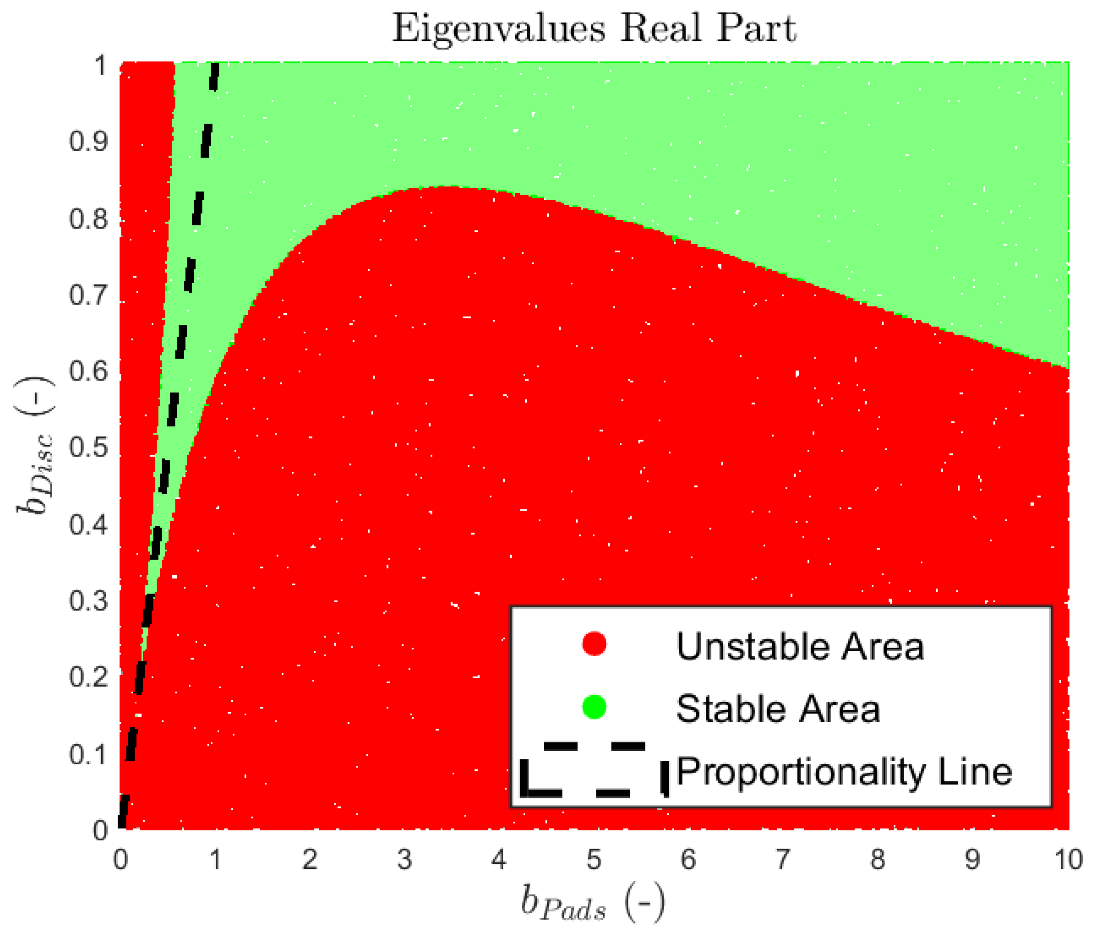
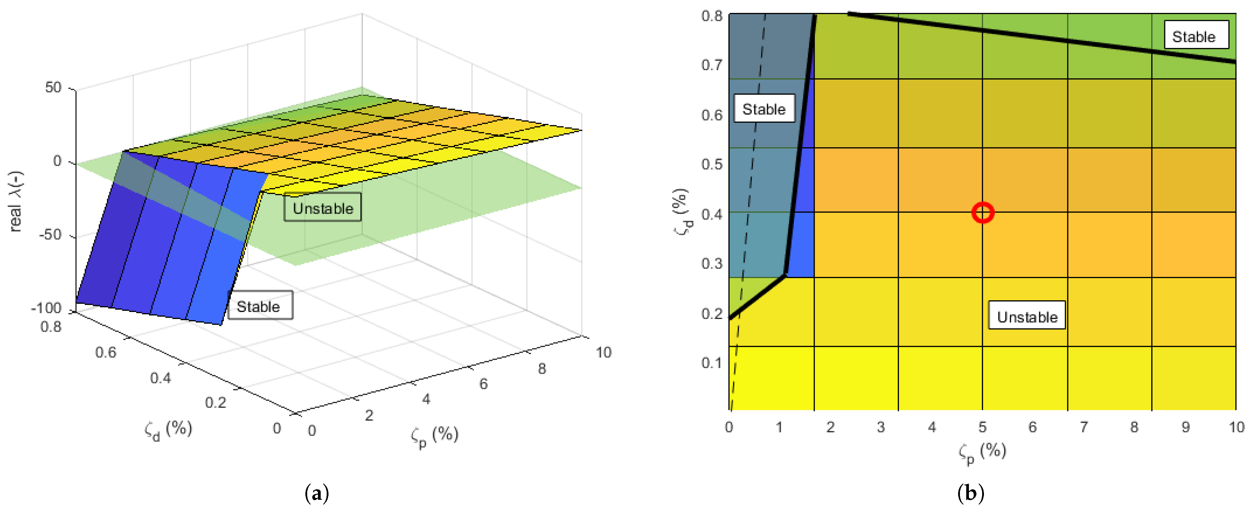
Figure 11a shows the maximum of all calculated real parts of eigenvalues
for different damping ratios of the disc
and the FM
. The green surface separates the stable and unstable solutions, where all solutions above this surface are unstable and all solutions below the surface are stable.
Figure 11b shows a detailed 2D view of the obtained stability areas. Solid lines represent the boundary between stable and unstable areas. The dashed line represents a proportionally damped system, where the damping of the disc
and the FM
have the same values. The red dot on the graph represents the default damping for the disc and the FM. The results showed that the behavior of the system with default damping is unstable. If the system was proportionally damped, it would be stabilized at a damping ratio value of about
; increasing it would make the system more stable, which agrees with the theory of proportional damping playing a purely stabilizing role in nonconservative systems. Based on the actual situation, the given system and the given unstable mode could be stabilized by the suitable adjustment of the damping of the FM and the disc. If the damping of the disc is maintained, the damping of the FM would have to be reduced to bring the system into a stable area. If the damping ratio of the FM is reduced below
, the system would become stable, which is contra-intuitive. If constant FM damping is considered, the disc damping would have to reach a value of almost
for the system to be stable.
4. Discussion
In this study, we examined the effect of damping on the stability of a particular disc brake system to assess the importance of components damping in terms of stability and thus brake squeal. The analysis was performed using simplified (2 DoF) and complex (multiple DoF) models of a disc brake. Various authors as well as the classical theory of vibration of mechanical systems state that in nonconservative systems, damping can play both a stabilizing as well as a destabilizing role.
Both analyzed models showed the dependence of stability on the degree of proportionality of damping. At low damping levels, the systems showed unstable behavior. Increasing the damping while maintaining its proportionality ultimately stabilized the system. However, this did not apply in the case of a deviation from proportional damping, where increasing the damping of one part of the structure at the expense of another led to destabilization. Since both models showed this action, regardless of the complexity, it implies that similar behavior can be anticipated in commercial disc brake systems. From the given observation, we concluded that an effective brake-squeal prediction process should account for damping.
Concerning the questions defined in the Introduction, both can be answered positively. Nonproportional damping can significantly influence the stability of disc brake systems. Our findings demonstrate that disc brake systems can contain unstable modes, which are, for common material properties, prone to being destabilized by dissipation-induced instability. However, from the scope of this research, we cannot conclude that all unstable modes are sensitive in this manner for physically reasonable material properties, especially damping propensity.
Nonproportional damping can be modeled in modern FEM tools using material-dependent damping models. By definition of specific material-dependent damping, for single components, this leads to a nonproportional damping matrix relative to the mass and stiffness matrices of a system. This allows appraising unstable system modes’ sensitivity to damping.
Here, we experimentally confirmed hypotheses from previous research [
12,
20]. Two coalescent patterns in the brake system can have different modal damping ratios, potentially leading to dissipation-induced instability. In this research, the damping matrix was not synthesized artificially using the coefficients to change the structure of the damping matrix to achieve general damping, as was done by Guillaume et al. [
12]; the damping matrix was constructed directly from the definition of material-dependent damping properties, making the resulting matrix nonproportional to the mass and stiffness matrices. This approach is effective since the desired damping model can be defined directly from the experimental measurement of components damping properties.
The novelty of this research is supporting the hypothesis of possible dissipation-induced instability occurrences in disc brake systems through analyses of a real experimental brake system with measured and justified damping properties.This paper shows a possible method of including material-dependent damping into modern FEM tools and performing analyses leading to a prediction of dissipation-induced instability in disc brake systems.


