
An Optimization Workflow in Design for Additive Manufacturing

 , ,
, ,  , , and
Abstract
1. Introduction
2. Design Workflow
3. Case Study
4. Conclusions
Author Contributions
Funding
Institutional Review Board Statement
Informed Consent Statement
Data Availability Statement
Conflicts of Interest
References
- Pei, E. Editorial PIAM October 2019. Prog. Addit. Manuf. 2019, 4, 355–356. [Google Scholar] [CrossRef]
- ISO/ASTM, ISO/ASTM 52900:2015 (ASTM F2792)—Additive Manufacturing--General Principles—Terminology; ISO International Organization for Standardization, ASTM American Society for Testing and Materials: Geneva, Switzerland; West Conshohocken, PA, USA, 2015.
- AM Platform, Additive Manufacturing Strategic Research Agenda. 2014. Available online: https://www.rm-platform.com/linkdoc/AM%20SRA%20-%20February%202014.pdf (accessed on 12 March 2021).
- SASAM. Additive Manufacturing: SASAM Standardisation Roadmap. 2015. Available online: https://www.rm-platform.com/downloads2/summary/50-strategic-research-agenda/608-sasam-standardisation-roadmap-open-june-2015 (accessed on 12 March 2021).
- FoFAM. Additive Manufacturing Roadmap: Gaps and Actions on Market Driven Value Chains. 2016. Available online: https://portal.effra.eu/result/show/1080 (accessed on 12 March 2021).
- America Makes, ANSI, Standardization Roadmap for Additive Manufacturing—Version 1.0. 2017. Available online: https://share.ansi.org/Shared%20Documents/Standards%20Activities/AMSC/AMSC_Roadmap_February_2017.pdf (accessed on 12 March 2021).
- America Makes, ANSI, Standardization Roadmap for Additive Manufacturing—Version 2.0. 2018. Available online: https://www.americamakes.us/america-makes-ansi-standardization-roadmap-additive-manufacturing-presented-formnext-conference/ (accessed on 12 March 2021).
- Savio, G.; Meneghello, R.; Rosso, S.; Concheri, G. 3D model representation and data exchange for additive manufacturing. In Lecture Notes in Mechanical Engineering; Springer: Cham, Switzerland, 2019; pp. 412–421. [Google Scholar] [CrossRef]
- Bacciaglia, A.; Ceruti, A.; Liverani, A. A systematic review of voxelization method in additive manufacturing. Mech. Ind. 2019, 20, 630. [Google Scholar] [CrossRef]
- Grigolato, L.; Rosso, S.; Meneghello, R.; Concheri, G.; Savio, G. Heterogeneous objects representation for Additive Manufacturing: A review. Instant J. Mech. Eng. 2019, 14–23. [Google Scholar] [CrossRef]
- Thompson, M.K.; Moroni, G.; Vaneker, T.; Fadel, G.; Campbell, R.I.; Gibson, I.; Bernard, A.; Schulz, J.; Graf, P.; Ahuja, B.; et al. Design for Additive Manufacturing: Trends, opportunities, considerations, and constraints. CIRP Ann.-Manuf. Technol. 2016, 65, 737–760. [Google Scholar] [CrossRef]
- Benedetti, M.; du Plessis, A.; Ritchie, R.; Dallago, M.; Razavi, S.; Berto, F. Architected cellular materials: A review on their mechanical properties towards fatigue-tolerant design and fabrication. Mater. Sci. Eng. R Rep. 2021, 144, 100606. [Google Scholar] [CrossRef]
- Raghavendra, S.; Molinari, A.; Dallago, M.; Zappini, G.; Zanini, F.; Carmignato, S.; Benedetti, M. Uniaxial static mechanical properties of regular, irregular and random additively manufactured cellular materials: Nominal vs. real geometry. Forces Mech. 2021, 2, 100007. [Google Scholar] [CrossRef]
- Calignano, F.; Lorusso, M.; Roppolo, I.; Minetola, P. Investigation of the Mechanical Properties of a Carbon Fibre-Reinforced Nylon Filament for 3D Printing. Machines 2020, 8, 52. [Google Scholar] [CrossRef]
- Allevi, G.; Capponi, L.; Castellini, P.; Chiariotti, P.; Docchio, F.; Freni, F.; Marsili, R.; Martarelli, M.; Montanini, R.; Pasinetti, S.; et al. Investigating Additive Manufactured Lattice Structures: A Multi-Instrument Approach. IEEE Trans. Instrum. Meas. 2020, 69, 2459–2467. [Google Scholar] [CrossRef]
- Bourell, D.L.; Rosen, D.W.; Leu, M.C. The roadmap for additive manufacturing and its impact. 3D Print. Addit. Manuf. 2014, 1, 6–9. [Google Scholar] [CrossRef]
- Seifi, M.; Gorelik, M.; Waller, J.; Hrabe, N.; Shamsaei, N.; Daniewicz, S.; Lewandowski, J.J. Progress Towards Metal Additive Manufacturing Standardization to Support Qualification and Certification. JOM 2017, 69, 439–455. [Google Scholar] [CrossRef]
- Bacciaglia, A.; Ceruti, A.; Liverani, A. Proposal of a standard for 2D representation of bio-inspired lightweight lattice structures in drawings. Proc. Inst. Mech. Eng. Part C J. Mech. Eng. Sci. 2020, 095440622095159. [Google Scholar] [CrossRef]
- The Economist Intelligence Unit. Adding It Up: The Economic Impact of Additive Manufacturing; Agency for Science, Technology and Research (A* STAR): Singapore, 2018; 24p. [Google Scholar]
- Ullman, D.G. The Mechanical Design Process, 4th ed.; McGraw-Hill: New York, NY, USA, 2010. [Google Scholar] [CrossRef]
- Chakrabarti, A. Engineering Design Synthesis: Understanding, Approaches, and Tools; Springer: London, UK, 2002. [Google Scholar]
- Cagan, J.; Campbell, M.I.; Finger, S.; Tomiyama, T. A Framework for Computational Design Synthesis: Model and Applications. J. Comput. Inf. Sci. Eng. 2005, 5, 171. [Google Scholar] [CrossRef]
- Shea, K.; Cagan, J. Innovative dome design: Applying geodesic patterns with shape annealing. Artif. Intell. Eng. Des. Anal. Manuf. 1997, 11, 379. [Google Scholar] [CrossRef]
- Gibson, I.; Rosen, D.; Stucker, B.; Khorasani, M. Additive Manufacturing Technologies; Springer International Publishing: Cham, Switzerland, 2021. [Google Scholar] [CrossRef]
- Rosen, D.W. Computer-Aided Design for Additive Manufacturing of Cellular Structures. Comput. Aided Des. Appl. 2007, 4, 585–594. [Google Scholar] [CrossRef]
- Ponche, R.; Kerbrat, O.; Mognol, P.; Hascoet, J.Y. A novel methodology of design for Additive Manufacturing applied to Additive Laser Manufacturing process. Robot. Comput. Integr. Manuf. 2014, 30, 389–398. [Google Scholar] [CrossRef]
- Vayre, B.; Vignat, F.; Villeneuve, F. Designing for Additive Manufacturing. Procedia CIRP 2012, 632–637. [Google Scholar] [CrossRef]
- Briard, T.; Segonds, F.; Zamariola, N. G-DfAM: A methodological proposal of generative design for additive manufacturing in the automotive industry. Int. J. Interact. Des. Manuf. 2020, 14, 875–886. [Google Scholar] [CrossRef]
- Duro-Royo, J.; Mogas-Soldevila, L.; Oxman, N. Flow-based fabrication: An integrated computational workflow for design and digital additive manufacturing of multifunctional heterogeneously structured objects. Comput. Des. 2015, 69, 143–154. [Google Scholar] [CrossRef]
- Boddeti, N.; Ding, Z.; Kaijima, S.; Maute, K.; Dunn, M.L. Simultaneous Digital Design and Additive Manufacture of Structures and Materials. Sci. Rep. 2018, 8, 15560. [Google Scholar] [CrossRef]
- Zhang, Y.; Bernard, A.; Gupta, R.K.; Harik, R. Evaluating the design for additive manufacturing: A process planning perspective. Procedia CIRP 2014, 21, 144–150. [Google Scholar] [CrossRef]
- Lettori, J.; Raffaeli, R.; Peruzzini, M.; Schmidt, J.; Pellicciari, M. Additive manufacturing adoption in product design: An overview from literature and industry. Procedia Manuf. 2020, 51, 655–662. [Google Scholar] [CrossRef]
- Motyl, B.; Filippi, S. Investigating the Relationships between Additive Manufacturing and TRIZ: Trends and Perspectives. In Lecture Notes in Mechanical Engineering; Springer: Cham, Switzerland, 2019; pp. 903–911. [Google Scholar] [CrossRef]
- Altshuller, G. And Suddenly the Inventor Appeared: TRIZ, the Theory of Inventive Problem Solving, Worcester. 1996. Available online: http://books.google.com/books?hl=en&lr=&id=s7Qk_6WELWUC&oi=fnd&pg=PA1&dq=And+Suddenly+the+Inventor+Appeared&ots=2Fc3TJGicr&sig=b5C0LEyulNyiMQVfz-cOx0FPdrU (accessed on 19 November 2020).
- Seepersad, C.C. Challenges and Opportunities in Design for Additive Manufacturing. 3D Print. Addit. Manuf. 2014, 1, 10–13. [Google Scholar] [CrossRef]
- Kumke, M.; Watschke, H.; Vietor, T. A new methodological framework for design for additive manufacturing. Virtual Phys. Prototyp. 2016, 11, 3–19. [Google Scholar] [CrossRef]
- Pahl, G.; Beitz, W.; Feldhusen, J.; Grote, K.-H. Engineering Design: A Systematic Approach; Springer: London, UK, 2007. [Google Scholar] [CrossRef]
- Rozvany, G.I.N. A critical review of established methods of structural topology optimization. Struct. Multidiscip. Optim. 2009, 37, 217–237. [Google Scholar] [CrossRef]
- Bendsøe, M.P.; Kikuchi, N. Generating optimal topologies in structural design using a homogenization method. Comput. Methods Appl. Mech. Eng. 1988, 71, 197–224. [Google Scholar] [CrossRef]
- Hassani, B.; Hinton, E. Homogenization and Structural Topology Optimization; Springer: London, UK, 1999. [Google Scholar] [CrossRef]
- Savio, G.; Curtarello, A.; Rosso, S.; Meneghello, R.; Concheri, G. Homogenization driven design of lightweight structures for additive manufacturing. Int. J. Interact. Des. Manuf. 2019. [Google Scholar] [CrossRef]
- Bendsøe, M.P. Optimal shape design as a material distribution problem. Struct. Optim. 1989, 1, 193–202. [Google Scholar] [CrossRef]
- Xie, Y.; Steven, G. A simple evolutionary procedure for structural optimization. Comput. Struct. 1993, 49, 885–896. [Google Scholar] [CrossRef]
- Querin, O.; Steven, G.; Xie, Y. Evolutionary structural optimisation (ESO) using a bidirectional algorithm. Eng. Comput. 1998, 15, 1031–1048. [Google Scholar] [CrossRef]
- Haber, R.; Bendsøe, M. Problem formulation, solution procedures and geometric modeling: Key issues in variable-topology optimization. In Proceedings of the 7th AIAA/USAF/NASA/ISSMO Symposium on Multidisciplinary Analysis and Optimization, St. Louis, MO, USA, 2–4 September 1998; American Institute of Aeronautics and Astronautics Inc., AIAA: Reston, VA, USA; pp. 1864–1873. [CrossRef]
- van Dijk, N.P.; Maute, K.; Langelaar, M.; van Keulen, F. Level-set methods for structural topology optimization: A review. Struct. Multidiscip. Optim. 2013, 48, 437–472. [Google Scholar] [CrossRef]
- Sigmund, O. A 99 line topology optimization code written in matlab. Struct. Multidiscip. Optim. 2001, 21, 120–127. [Google Scholar] [CrossRef]
- Andreassen, E.; Clausen, A.; Schevenels, M.; Lazarov, B.S.; Sigmund, O. Efficient topology optimization in MATLAB using 88 lines of code. Struct. Multidiscip. Optim. 2011, 43, 1–16. [Google Scholar] [CrossRef]
- Zegard, T.; Paulino, G.H. Bridging topology optimization and additive manufacturing. Struct. Multidiscip. Optim. 2016, 53, 175–192. [Google Scholar] [CrossRef]
- Jiu, L.; Zhang, W.; Meng, L.; Zhou, Y.; Chen, L. A CAD-oriented structural topology optimization method. Comput. Struct. 2020, 239, 106324. [Google Scholar] [CrossRef]
- Wang, H.V. A Unit Cell Approach for Lightweight Structure and Compliant Mechanism. Ph.D. Dissertation, Georgia Institute of Technology, Atlanta, GA, USA, 2005. [Google Scholar]
- Savio, G.; Gaggi, F.; Meneghello, R.; Concheri, G. Design method and taxonomy of optimized regular cellular structures for additive manufacturing technologies. Proc. Int. Conf. Eng. Des. ICED 2015, 4, 235–244. Available online: https://www.designsociety.org/publication/37788/design_method_and_taxonomy_of_optimized_regular_cellular_structures_for_additive_manufacturing_technologies (accessed on 12 March 2021).
- Savio, G.; Meneghello, R.; Concheri, G. Optimization of lattice structures for additive manufacturing technologies. In Advances on Mechanics, Design Engineering and Manufacturing. Lecture Notes in Mechanical Engineering; Springer: Cham, Switzerland, 2016; pp. 213–222. [Google Scholar] [CrossRef]
- Savio, G.; Meneghello, R.; Concheri, G. Geometric modeling of lattice structures for additive manufacturing. Rapid Prototyp. J. 2018, 24, 351–360. [Google Scholar] [CrossRef]
- Catmull, E.; Clark, J. Recursively generated B-spline surfaces on arbitrary topological meshes. Comput. Des. 1978, 10, 350–355. [Google Scholar] [CrossRef]
- Rosso, S.; Meneghello, R.; Biasetto, L.; Grigolato, L.; Concheri, G.; Savio, G. In-depth comparison of polyamide 12 parts manufactured by Multi Jet Fusion and Selective Laser Sintering. Addit. Manuf. 2020, 36, 101713. [Google Scholar] [CrossRef]
- Rosso, S.; Meneghello, R.; Concheri, G.; Savio, G. Scale and Shape Effects on the Fatigue Behaviour of Additively Manufactured SS316L Structures: A Preliminary Study. In Lecture Notes in Mechanical Engineering; Springer: Cham, Switzerland, 2019; pp. 879–890. [Google Scholar] [CrossRef]
- Savio, G.; Rosso, S.; Curtarello, A.; Meneghello, R.; Concheri, G. Implications of modeling approaches on the fatigue behavior of cellular solids. Addit. Manuf. 2019, 25, 50–58. [Google Scholar] [CrossRef]
- Wu, Z.; Xia, L.; Wang, S.; Shi, T. Topology optimization of hierarchical lattice structures with substructuring. Comput. Methods Appl. Mech. Eng. 2019, 345, 602–617. [Google Scholar] [CrossRef]
- Alzahrani, M.; Choi, S.K.; Rosen, D.W. Design of truss-like cellular structures using relative density mapping method. Mater. Des. 2015, 85, 349–360. [Google Scholar] [CrossRef]
- Savio, G.; Meneghello, R.; Concheri, G. Design of variable thickness triply periodic surfaces for additive manufacturing. Prog. Addit. Manuf. 2019, 4, 281–290. [Google Scholar] [CrossRef]
- Jiang, J.; Xu, X.; Stringer, J. Optimization of process planning for reducing material waste in extrusion based additive manufacturing. Robot. Comput. Manuf. 2019, 59, 317–325. [Google Scholar] [CrossRef]
- Ahsan, A.N.; Habib, A.; Khoda, B. Resource based process planning for additive manufacturing. CAD Comput. Aided Des. 2015, 69, 112–125. [Google Scholar] [CrossRef]
- Cicconi, P.; Mandorli, M.; Favi, C.; Campi, F.; Germani, M. Metal Additive Manufacturing for the Rapid Prototyping of Shaped Parts: A Case Study. Comput. Des. Appl. 2021, 18, 1061–1079. [Google Scholar] [CrossRef]
- Song, X.; Feih, S.; Zhai, W.; Sun, C.-N.; Li, F.; Maiti, R.; Wei, J.; Yang, Y.; Oancea, V.; Brandt, L.; et al. Advances in additive manufacturing process simulation: Residual stresses and distortion predictions in complex metallic components. Mater. Des. 2020, 193, 108779. [Google Scholar] [CrossRef]
- Schoinochoritis, B.; Chantzis, D.; Salonitis, K. Simulation of metallic powder bed additive manufacturing processes with the finite element method: A critical review. Proc. Inst. Mech. Eng. Part B J. Eng. Manuf. 2016, 231, 96–117. [Google Scholar] [CrossRef]
- Gong, X.; Cheng, B.; Price, S.; Chou, K. Powder-bed electron-beam-melting additive manufacturing: Powder characterization, process simulation and metrology. In Proceedings of the 2013 ASME Early Career Technical Conference (ECTC), Birmingham, AL, USA, 2–3 November 2013; pp. 55–66. Available online: https://www.researchgate.net/publication/275960612 (accessed on 23 December 2020).
- Martukanitz, R.; Michaleris, P.; Palmer, T.; DebRoy, T.; Liu, Z.-K.; Otis, R.; Heo, T.W.; Chen, L.-Q. Toward an integrated computational system for describing the additive manufacturing process for metallic materials. Addit. Manuf. 2014, 1, 52–63. [Google Scholar] [CrossRef]
- Jayanath, S.; Achuthan, A. A computationally efficient hybrid model for simulating the additive manufacturing process of metals. Int. J. Mech. Sci. 2019, 160, 255–269. [Google Scholar] [CrossRef]
- Watanabe, N.; Shofner, M.L.; Treat, N.; Rosen, D.W. A model for residual stress and part warpage prediction in material extrusion with application to polypropylene. In Solid Freeform Fabrication 2016, Proceedings of the 27th Annual International Solid Freeform Fabrication Symposium—An Additive Manufacturing Conference, Austin, TX, USA, 8–10 August 2016; TMS: Pittsburgh, PA, USA, 2016; pp. 2437–2455. [Google Scholar]
- Brenken, B.; Barocio, E.; Favaloro, A.; Kunc, V.; Pipes, R.B. Development and validation of extrusion deposition additive manufacturing process simulations. Addit. Manuf. 2019, 25, 218–226. [Google Scholar] [CrossRef]
- Fradl, D.; Panditaratne, J.; Bi, J.; Fu, R.; Oancea, V. Finite Element Simulation of the Multi Jet Fusion (MJFTM) Process using Abaqus. In Proceedings of the SIMULIA Science in the Age of Experience, Chicago, IL, USA, 15–18 May 2017; pp. 440–469. Available online: https://pdfs.semanticscholar.org/fb66/17aab5ff74f47709ebfecb694d32f23ceff2.pdf (accessed on 23 January 2020).
- Kolossov, S.; Boillat, E.; Glardon, R.; Fischer, P.; Locher, M. 3D FE simulation for temperature evolution in the selective laser sintering process. Int. J. Mach. Tools Manuf. 2004, 44, 117–123. [Google Scholar] [CrossRef]
- Preisinger, C. Linking Structure and Parametric Geometry. Arch. Des. 2013, 83, 110–113. [Google Scholar] [CrossRef]
- Renishaw, Data Sheets—Additive Manufacturing—AlSi10Mg-0403 (400 W). 2021. Available online: https://www.renishaw.com/en/data-sheets-additive-manufacturing--17862 (accessed on 19 February 2021).


| Density | 2700 kg/m3 |
| Young modulus | 68 GPa |
| Yield strength | 190 MPa |
| Ultimate tensile strength | 335 MPa |
| Poisson Ratio | 0.30 |
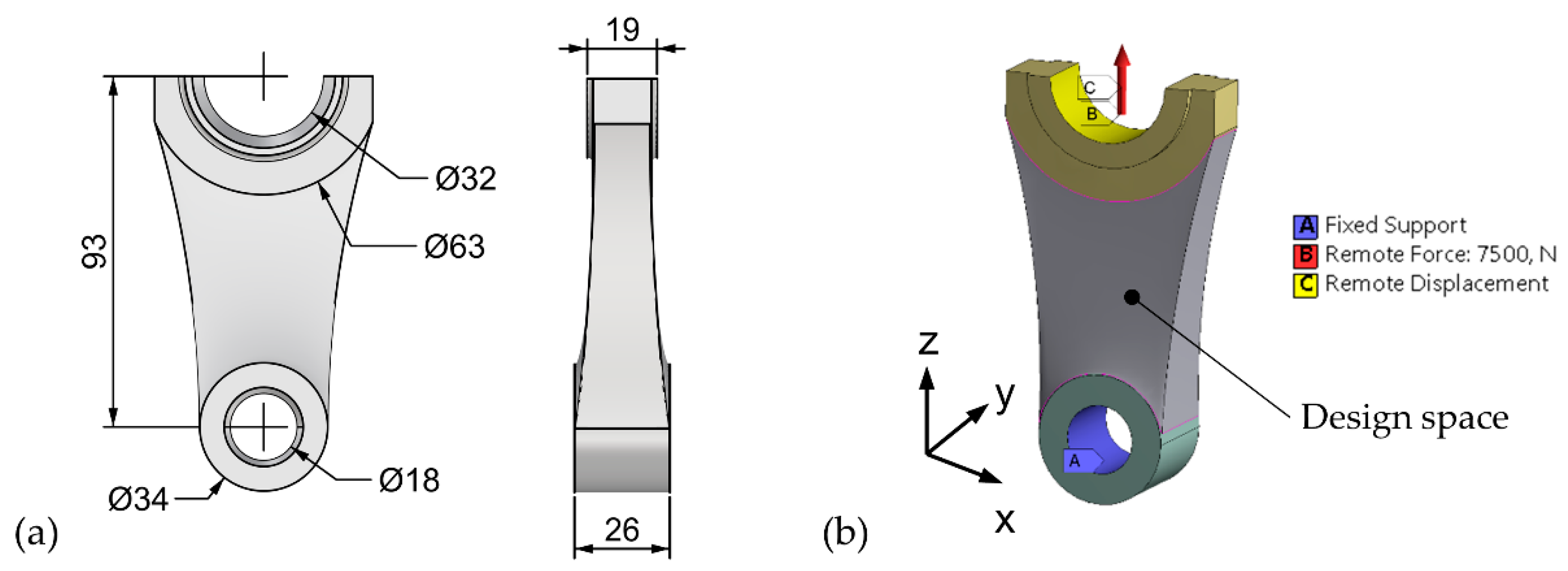
| Load | 7.5 kN axial traction along z-axis. |
| Applies to big rod’s end face. | |
| Constraints | All the displacements and rotations locked. |
| Applies to inner face of the small rod’s end. | |
| Displacements along x- and y-directions locked. | |
| Applies to big rod’s end face. |
| Model/Approach | Mass [g] | % of Mass Reduction |
|---|---|---|
| Starting design space | 104.7 | |
| Topology optimization | 29.99 | −71% |
| Size optimization | 20.98 | −80% |
Publisher’s Note: MDPI stays neutral with regard to jurisdictional claims in published maps and institutional affiliations. |
© 2021 by the authors. Licensee MDPI, Basel, Switzerland. This article is an open access article distributed under the terms and conditions of the Creative Commons Attribution (CC BY) license (http://creativecommons.org/licenses/by/4.0/).
Share and Cite
Rosso, S.; Uriati, F.; Grigolato, L.; Meneghello, R.; Concheri, G.; Savio, G. An Optimization Workflow in Design for Additive Manufacturing. Appl. Sci. 2021, 11, 2572. https://doi.org/10.3390/app11062572
Rosso S, Uriati F, Grigolato L, Meneghello R, Concheri G, Savio G. An Optimization Workflow in Design for Additive Manufacturing. Applied Sciences. 2021; 11(6):2572. https://doi.org/10.3390/app11062572
Chicago/Turabian StyleRosso, Stefano, Federico Uriati, Luca Grigolato, Roberto Meneghello, Gianmaria Concheri, and Gianpaolo Savio. 2021. "An Optimization Workflow in Design for Additive Manufacturing" Applied Sciences 11, no. 6: 2572. https://doi.org/10.3390/app11062572
APA StyleRosso, S., Uriati, F., Grigolato, L., Meneghello, R., Concheri, G., & Savio, G. (2021). An Optimization Workflow in Design for Additive Manufacturing. Applied Sciences, 11(6), 2572. https://doi.org/10.3390/app11062572