Review

Geometrical Degrees of Freedom for Cellular Structures Generation: A New Classification Paradigm

1
Multi-Scale Additive Manufacturing Lab, University of Waterloo, Waterloo, ON N2L 3G1, Canada
2
Department Mechanical and Mechatronics Engineering, University of Waterloo, Waterloo, ON N2L 3G1, Canada
*
Author to whom correspondence should be addressed.
Appl. Sci. 2021, 11(9), 3845; https://doi.org/10.3390/app11093845
Submission received: 8 March 2021 / Revised: 19 April 2021 / Accepted: 21 April 2021 / Published: 23 April 2021
(This article belongs to the Special Issue Design for Additive Manufacturing: Methods and Tools)

Abstract

:
Cellular structures (CSs) have been used extensively in recent years, as they offer a unique range of design freedoms. They can be deployed to create parts that can be lightweight by introducing controlled porous features, while still retaining or improving their mechanical, thermal, or even vibrational properties. Recent advancements in additive manufacturing (AM) technologies have helped to increase the feasibility and adoption of cellular structures. The layer-by-layer manufacturing approach offered by AM is ideal for fabricating CSs, with the cost of such parts being largely independent of complexity. There is a growing body of literature concerning CSs made via AM; this presents an opportunity to review the state-of-the-art in this domain and to showcase opportunities in design and manufacturing. This review will propose a novel way of classifying cellular structures by isolating their Geometrical Degrees of Freedom (GDoFs) and will explore the recent innovations in additively manufactured CSs. Based on the present work, the design inputs that are common in CSs generation will be highlighted. Furthermore, the work explores examples of how design inputs have been used to drive the design domain through various case studies. Finally, the review will highlight the manufacturability limitations of CSs in AM.

1. Introduction

Cellular structures (CSs) are hierarchical materials that are composed of repetitive unit cells. CSs are an intrinsic part of nature; examples are found in bones, wood and seashells. Such materials are known to impart a balance between weight and strength. Over the past decades, CSs have gained a growing focus in design for industrial and biomedical applications. Such applications vary from structural components [1,2,3], where the stiffness and strength of a part can be controlled based on external data, to vibrational [4,5], where a well-selected CS can be used as a shock absorber in a car, as well as thermal [6,7] where CSs may be used to enhance heat transfer, or in mass transport in the case of scaffolds for implants [8].
The growing popularity of CSs correlates positively with the increasing popularity and adoption of AM processes, where a design is printed layer per layer. As such, AM fabrication enables users to achieve higher design complexity than traditional manufacturing methods [9,10]. For example, using AM technologies, porosity can be varied non-uniformly across the volume of a product to tailor one side of a part to be stiffer than the other using AM [11], without necessarily increasing the manufacturing cost. Using the layer-by-layer AM principle, it is possible to build micro-architected materials with controlled properties [12]. This review paper presents recent research advancements in CSs; more precisely, this work reviews how the advent of AM and Design for Additive Manufacturing (DfAM) have expanded the opportunities for manufacturing CSs and highlights the limitations and opportunities in fabricating such structures. As such, the focus of this work is twofold:
  • To review the design and geometrical considerations for CS and their classification based on unit cell feature properties.
  • To highlight the manufacturability limitations and opportunities in DfAM with CSs.
In recent years, a few other articles have focused on reviewing one specific or more aspects of AM cellular structures [13,14,15,16,17,18,19]. Other reviews have focused on specific types of porous structures, such as biodegradable structures for porous implants [20,21,22], Functionally Gradient Material (FGM) or Gradient Lattice Structures (GLS) [23,24]. Furthermore, some reviews have touched to some extent on all the aspects CSs [25]. This review will bring forth a new classification paradigm, in addition to highlighting the issues that are specifically related to additively manufactured CSs.

2. Design and Geometrical Consideration

2.1. Cellular Structure Design Classification

There are numerous classifications of CS that have already been established, such as the work by Tang and Zhao [26]. The basis for the classification, presented in the present work, is inspired by these existing classifications and attempts to further harmonize the available literature in this space. Tang and Zhao [26] have divided CSs into three structural design classes: foam structures, two-dimensional (2D) CSs referring to extruded 2D cells and three-dimensional (3D) CSs referring to structures that periodically repeat in 3D. They then described an emerging classification for 3D CSs, which is based on how ordered the CSs are, ranging from randomized to pseudo-periodic and periodic structures. The classification for this review work will consider both randomized and ordered classifications. Other classifications, such as the one by Hadi et al. [27], rely on the different types of design variables for CSs: patterns (referring to the characteristics of the minimum CS unit replicated), surface limits (referring to the size of the shape of the CS boundary), progressivity (referring to the variation of the CS unit cell’s thickness) and conformity (referring to whether or not the CS unit cells are varied according to strict parameters). Many advances in the design of CSs have shown that there is a growing body of potential unit cells, with a push towards implicit modeling for the design of CSs. Therefore, in the present review, the CSs will not be classified based on their unit cells. In addition, some reviewers such as Tamburrino et al. [19] have divided CSs stochastic structures into open cells and closed cell foams. That concept also has its limitations, as there are examples of triply periodic minimal structures with a varying volume fraction, which can be seen as open on one end and completely closed on the other. Hence, it is more important to isolate the sources of morphology variation inside a CS rather than trying to classify them in different distinct, non-intersecting groups.
The present review challenges the current paradigm, which aims at grouping CSs into multiple distinct and non-overlapping groups. Instead, the current approach identifies the main geometric degrees of freedom (GDoF) that come into play when designing a CS.
It is important to first define some concepts that will recur throughout the article. The design space refers to the volume that contains the CS (the object being lightweight), and the Representative Volume Element (RVE) refers to the smallest element that is replicated throughout the design space. There are multiple types of RVEs and some of the most famous will be discussed later in Section 2.2. The RVE can vary throughout the design space in many ways: it can be transformed (scaled or rotated), its volume fraction can be changed and its topology/type can also be changed. The RVE can be modified to optimize the design space as a response to multiple factors: based on the boundary of the design space (or the surface of the design), based on the loads that are applied to the CS and based on random or external factors (such as trying to replicate the density of bones). All of those have been considered when creating Table 1.
The RVEs inside the CS may also vary based on both the loads and the boundary conditions, whereas for other CSs, their RVEs may be transformed and changed based on imposed volume fractions. Thus, certain case studies can appear in multiple entries on the table. This is the case for the work of Tang et al. [30], wherein the authors have generated a strut-based CS that considers the boundary of the design space where the strut-based RVE are then modified towards the surface of the part. However, the thickness of the struts is varied based on the load applied to the design space. That paper, therefore, appears in two locations in the CSs classification table. It is important to notice that several design paths can lead to the same design result. The purpose of the summary table is thus not to show that every entry is unique, rather to showcase all the design freedoms the designer has access to.
Another important thing to note is that it is extremely hard to create a classification that is exclusive; no matter the classification, there will always be a CS that can belong to multiple entries in any classification table. For example, the RVE can be changed in multiple ways and for multiple reasons. There are also varying degrees of randomness that can be attributed to a CS—some CS arrangement can be random in some locations and ordered in others. Table 1 shows the GDoFs that go into making a CS. In addition, the GDoFs that were selected to create the table did not include the type of RVE. With the advent of implicit modeling, there are more and more RVEs that emerge as design solutions, making a classification based on RVEs challenging to upkeep. The next sections will focus on some of the most popular and emerging RVEs in literature.

2.2. Overview of Representative Volume Elements
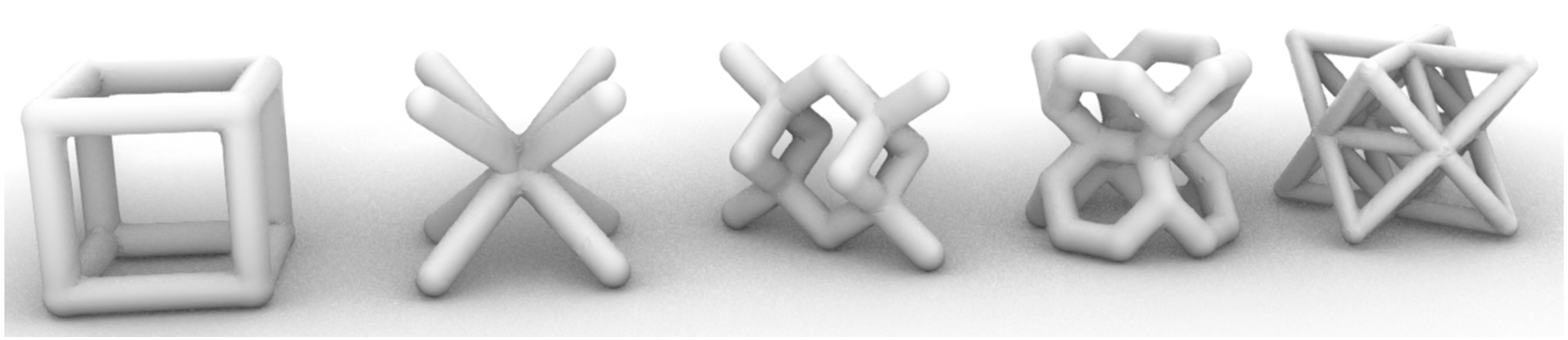
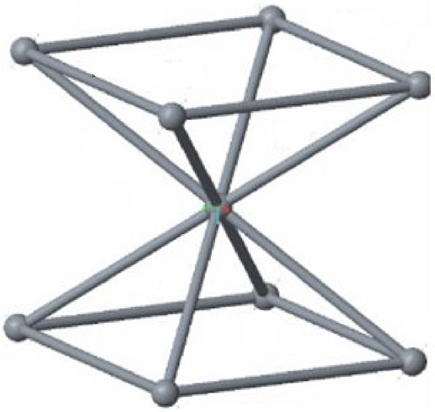
The smallest replicated unit or the representative volume element (RVE) alludes to the smallest unit that is replicated throughout the design domain or in a sub-region of a design domain; such RVEs are also referred to as unit cells. Below are the different existing types of RVEs or unit cells.

2.2.1. Strut-Based

Struts-based unit cells are RVEs with a specific arrangement of struts. Such examples of unit cells are presented in Figure 1. An emerging type of investigated strut-based unit cells are the ones used in bi-auxetic structures, from the Greek word “auxetos” meaning “that may increase”. Bi-auxetic structures are structures with a negative Poisson’s ratio [80], which means that when stretched in one direction, the structure expands in all other directions, whereas when compressed, the opposite is expected to happen. Auxetic materials have traditionally been fabricated through the use of foams; with the advent of AM such structures can be better tailored based on the intended application. Auxetic materials can be found in a few applications such as shock and sound-absorbing materials for vehicles and aircraft [80]. Other works, such as by Queheillalt and Wadley [81], have studied strut-based unit cells with hollow struts; hollow struts are not widely used as of now in the AM domain. The manufacturing of hollow struts still poses a problem in AM processes due to challenges in removing trapped powder or support materials within the struts.
Sometimes, the strut-based unit cell can just be one strut. For the classification in this review, when a CS is made of a truss network but does not contain any clear strut-based unit cell (an arrangement of strut replicated throughout the design space) then the RVE is considered to be a strut. An example is given by Smith et al. [39], whereby they describe a design methodology based on layout optimization where nodes distributed across the design space are interconnected by potential members. Those final members of the structures are chosen to minimize the total structural volume. Following this step, the size optimization algorithm uses the updated layout as the ground structure. Finally, in the last step, every member is resized to ensure that none of the members buckle [39].

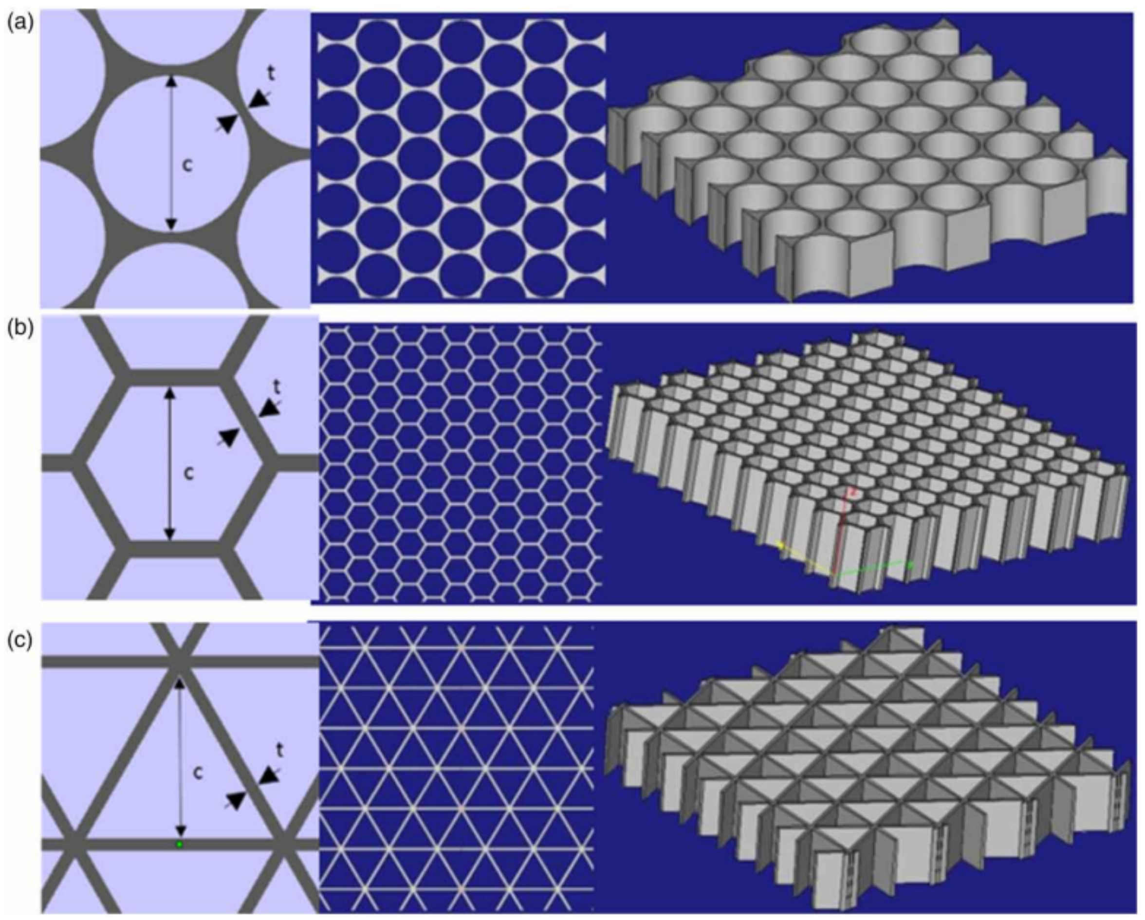
2.2.2. Extruded 2D Cells

Generally, 2D cellular structures can be described as CSs, where the repeated units are extrusions of polygons. The type of polygon that is extruded defines the type of extruded 2D CSs. Common extruded 2D CSs include Kagome, square, honeycomb [83], and triangular, as can be seen in Figure 2. The recent work from Ongaro offers an in-depth review of common extruded 2D CSs, as well as their mechanical simulation [69].
Furthermore, as it is shown by Hu and Wang [84], auxetic structures can also be made from extruded 2D cells. However, in that case, the expansion/contraction can only be done in the 2D plane perpendicular to the direction of the extrusion.
Figure 2. Extruded 2D unit cells with visualizations capturing a three-unit cell, a top view, and an isometric view of each configuration: (a) circular (c = 9.8 mm, t = 0.6 mm); (b) hexagonal (c = 3.125 mm, t = 0.6 mm); and (c) triangular (c = 9.14 mm, t = 0.6 mm) [85].
Applsci 11 03845 g002

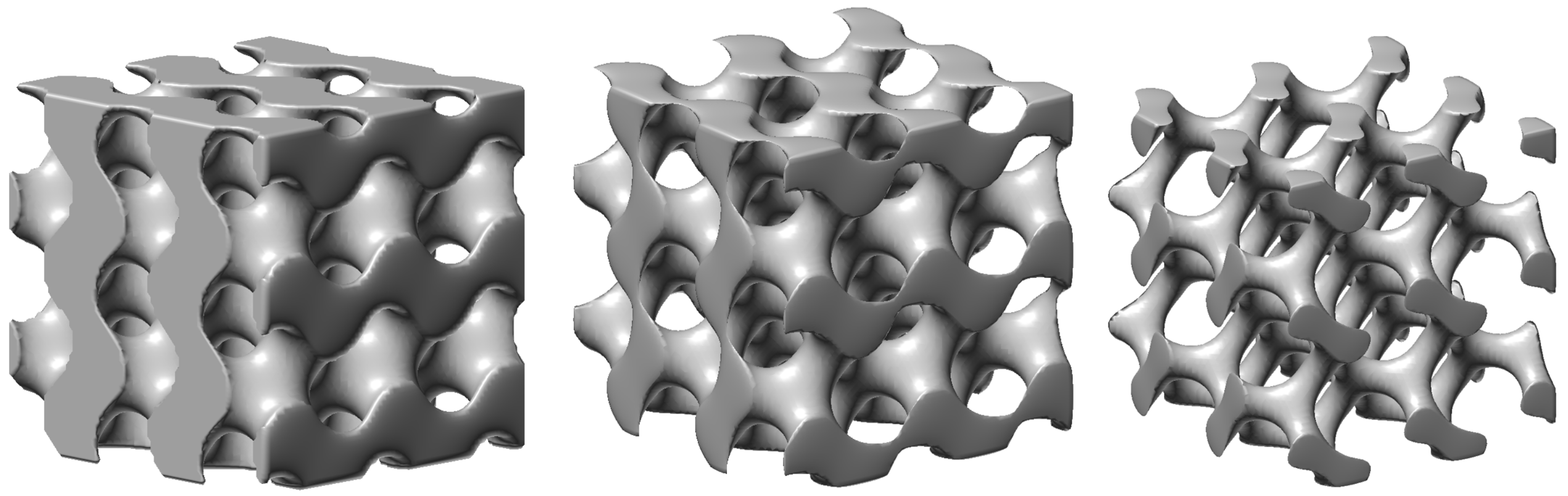
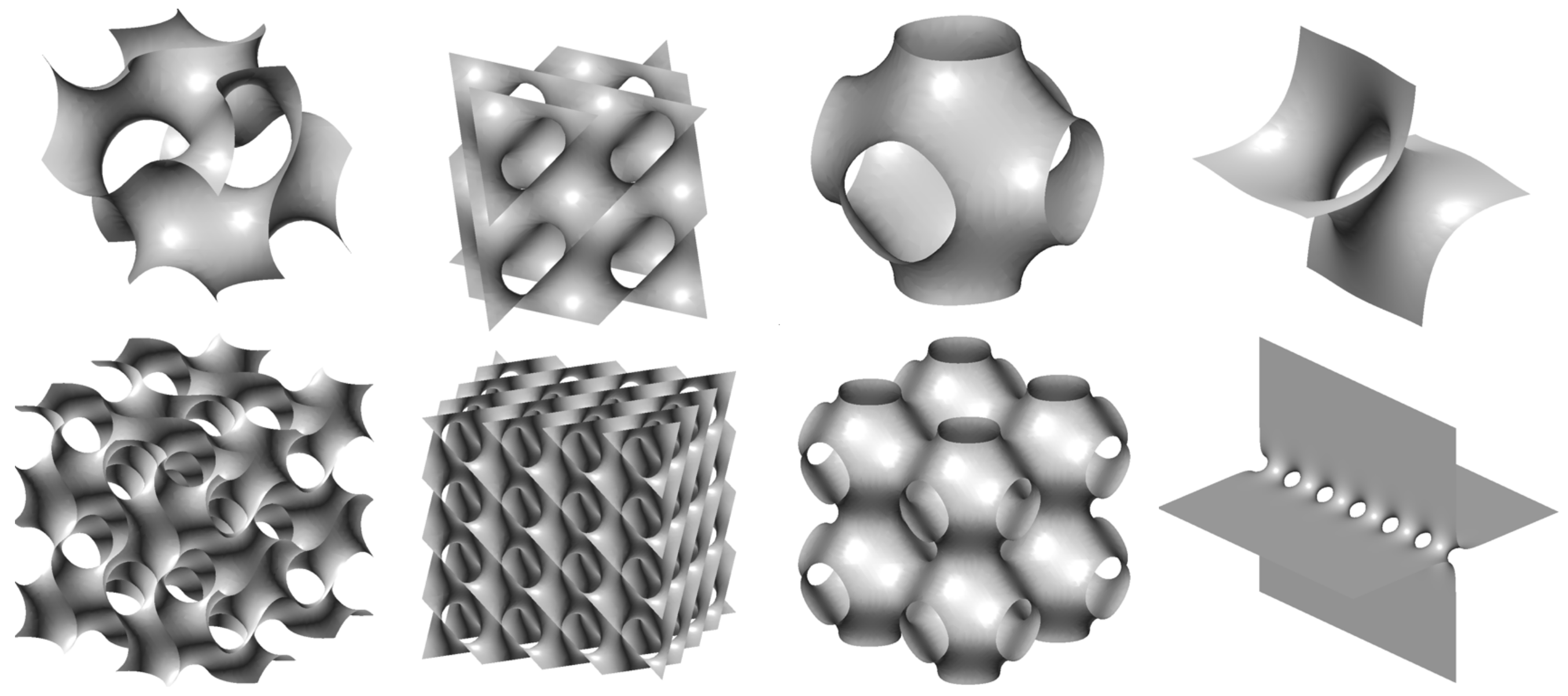
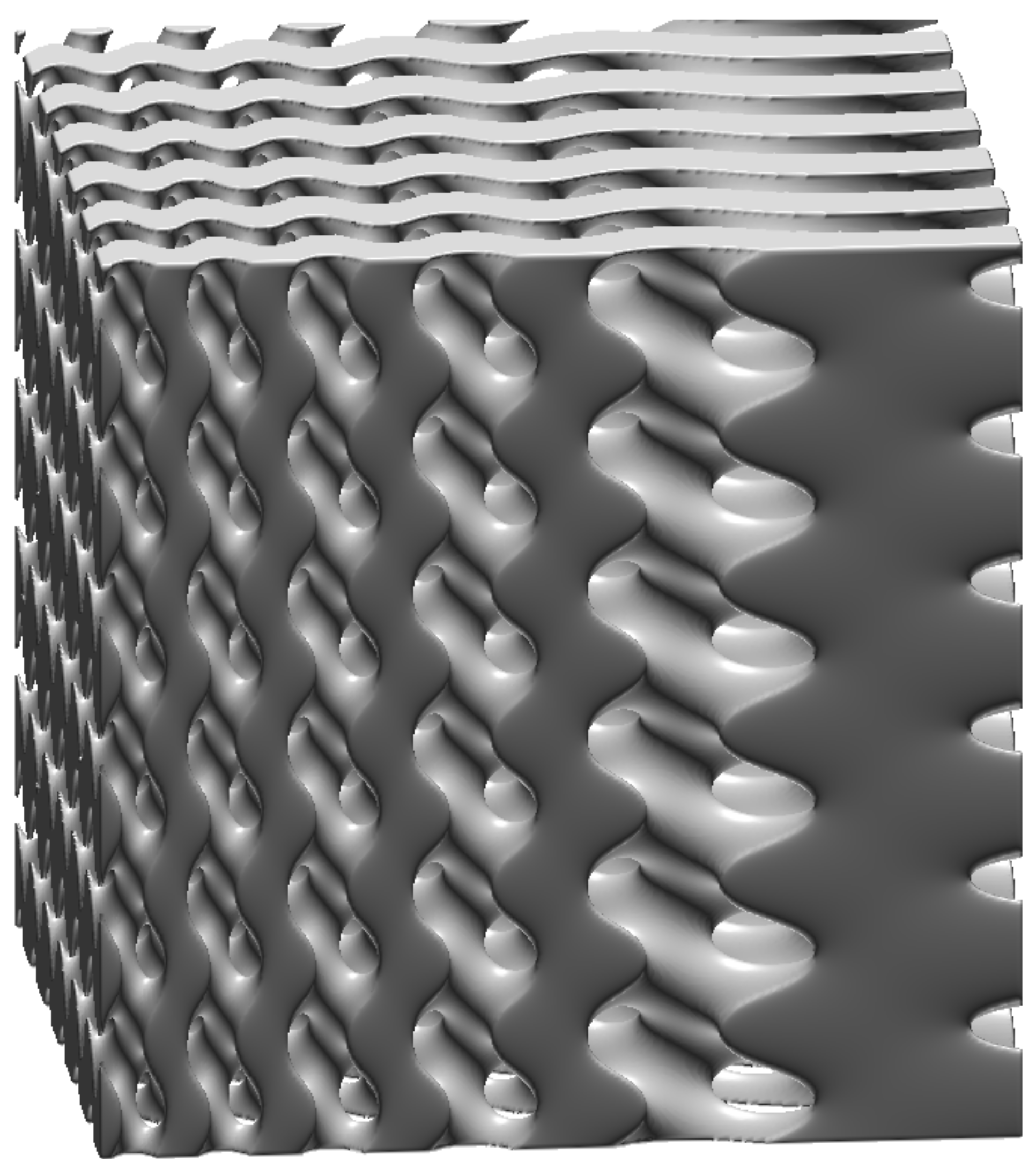
2.2.3. Triply Periodic Minimal Surfaces

Minimal surface areas have been researched for more than 200 years. A minimal surface area is a surface with the smallest area bounded by a contour [86]. Triply Periodic Minimal Surfaces (TPMS) are minimal surfaces in all three x, y and z directions.They are defined by an implicit function such as f ( x , y , z ) = t describing the locus of points at which the function takes the value t. To generate a solid structure or to describe a volume, the equation is replaced by an inequality, for instance f ( x , y , z ) < t . The function is used to define one unit cell, and the unit cell is replicated throughout the structure. The constant t can be adapted regionally to allow different volume fractions [13] (see Figure 3).
More specifically, a change in t will result in a different volume fraction. Since TPMSs are defined by functions, the transition between two unit cells is smooth, which means the structure has fewer stress concentrations. Hao et al. [87] have described an image-based algorithm and an implicit function to properly define a unit cell. Their unit cell is easy to discretize using finite element and it also minimizes the use of overhangs. Figure 4 shows a list of typical TPMS cells. Sometimes, there are simiarities between strut-based unit cells and TPMS. For example, Zhao et al. [88] have highlighted that controlling the volume fraction of the gyroid structure, one can get something close to the BCC lattice structure.

2.2.4. Unit Cells Obtained through Topology Optimization or Other Numerical Methods

According to Coelho et al. [73], TPMS-based RVEs are site-dependent, and it might be difficult for TPMS-based unit cells to balance scaffold elasticity and permeability. In contrast, Topologically Optimized Microstructures (TOMs) are microstructures that have been topologically optimized and smoothed; such microstructures can be deployed as the RVEs for CSs. Coelho et al. [73] suggest that such TOMs are advantageous over TPMS as they allow for anisotropic optimal design (Figure 5). Another way to obtain a TOM is described by Hollister [89]. The article shows one way to create libraries of unit cells to allow hierarchical design. There are two ways to construct those boundaries, either by image-based design approaches, or using CAD software. In the study, they rely heavily on imaging techniques to create the scaffold architecture with 3D anatomic defects. Globally, their process goes as follows: the microstructure is optimized for maximum permeability and the effective modulus must match the human bone tissue. Subsequently, they use imaging techniques to design the scaffold exterior. Following this, the global anatomic and architecture design are integrated. They then use AM to fabricate the design [89]. Similarly to Coelho et al. [73], Takezawa et al. [74] have used topology optimization to optimize the microstructures of parts.

2.2.5. Origami-Inspired Materials
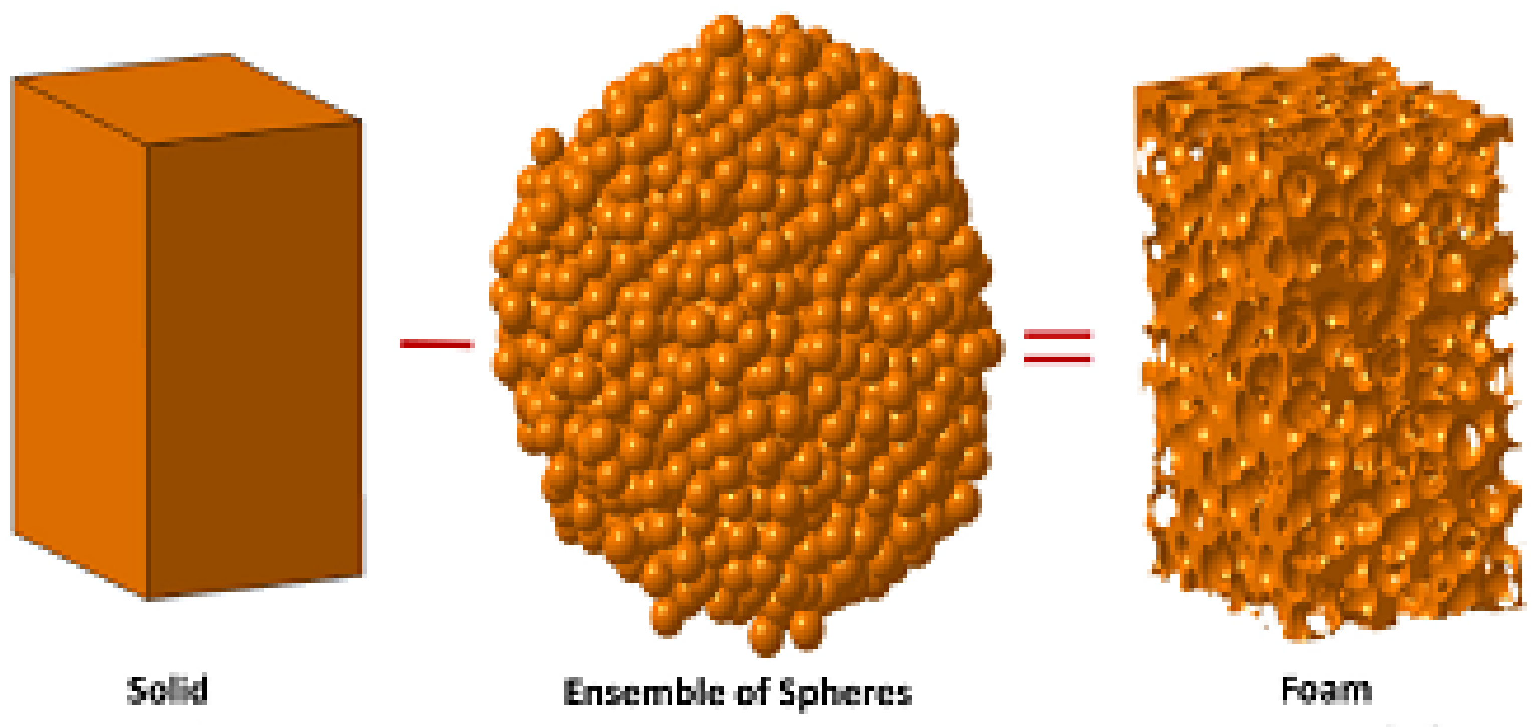
An emerging class of RVEs are based on origami-inspired materials. Such designs are comprised of stacked layers of material [90]. Figure 6 gives an example of how they are parametrized.

2.2.6. Void RVE

In some cases, the RVE is not the solid that is being stacked to create CSs, rather the RVE constitutes the solid material that is being removed to create the CSs. Some have discussed the need to remove random spheres in order to generate the CS [91]; this concept will also be discussed in further detail in Section 2.5.

2.2.7. Further thoughts on RVEs and CSs

It is important to mention that not all porous structures are CSs. CSs are obtained by the repetitiveness of an RVE, whether it is a solid RVE or a void RVE. Some examples of porous structures that are not considered to be CSs are structures that may result from topology optimization or other mathematical operations. Examples of other porous structures that are not CSs include Spinodoids [92] and structures that are the result of the thresholding of Gaussian fields Hyman and Winter [93]. Furthermore, many randomized structures seem to use Voronoi cells. A Voronoi cell can be observed in different ways. The RVE might be an edge of the cell, in which case the RVE is rotated and scaled throughout the design space. In some other instances, the RVE can be a Voronoi cell, which would mean that an RVE is defined by its number of vertices; in that case, since there are many polygons (in 2D) with different dimensions but the same number of vertices, the RVEs are varied (in type) but are also scaled or rotated.

2.3. RVE Variation Methods

2.3.1. RVE Morphology Variation

A CSs can vary in terms of the type of RVE (unit cell) present throughout the design space. The first column of Table 1 is dedicated to illustrating cases where there are RVE morphology variations. For example, Yang et al. [55] have proposed a method to vary the morphology of the CSs based on the location within the design space (see Figure 7). The authors were able to ensure a continuous transition between morphologies using control points. Varying the morphologies of the RVE based on the location can pave the way toward mimicking natural structures such as tissues by increasing the degrees of freedom required to locally control the properties of the material.
Jin et al. [56] have presented an interesting way of changing the morphology by superimposing two TPMSs. Varying the volume fraction of one TPMS based on the location is like changing the morphology of the resulting structure.

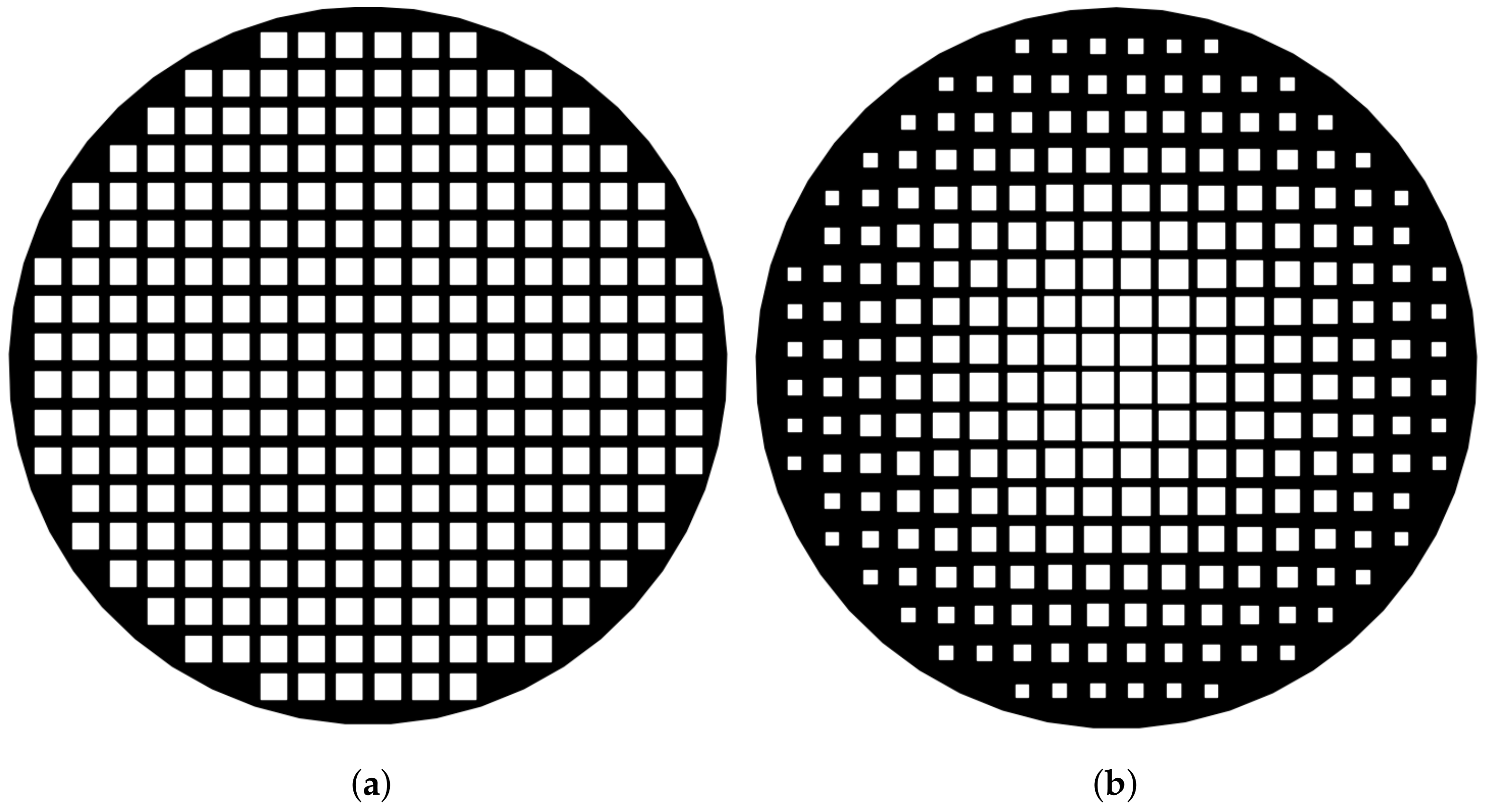
2.3.2. RVE Volume Fraction Variation

Volume fraction can also be varied to create porous Functionally Graded Materials (FGMs). In the case of a strut-based unit cell, volume fraction refers to the relative thickness of the struts. Figure 8 shows the difference between a structure with a constant volume fraction and a gradient volume fraction. The second column of Table 1 is dedicated to highlighting examples of research where the volume fraction of the RVE is changed throughout the CS to result in non-homogeneous properties.
Numerous papers have studied how to map the variation in the volume fraction (or conversely density) of CSs based on the gray scale gradient obtained from structural topology optimization algorithms. In such efforts, the typical goal is to ensure that the volume fraction of the RVE in the volume neighborhood maps to the topology optimization results in that region [11,30,51,94,95]. One such example is in the work by Alzahrani et al. [11], whereby they propose a method where the relative density is adjusted using the strut size in the structure. Similarly, Plocher and Panesar [29] have constructed multiple examples of CSs for which they have varied the density in a linear manner based on topologically optimized design spaces.

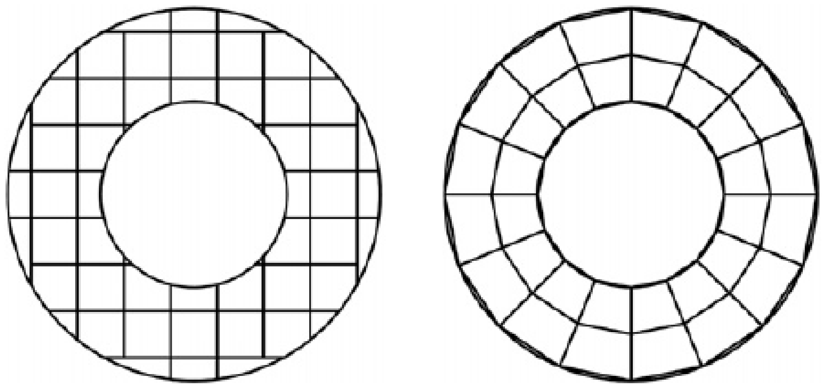
2.3.3. RVE Transformations

The third column of Table 1 is dedicated to cases where the volume fraction of the RVE undergoes scaling or rotation mathematical transformations. An example is shown in Figure 9. In some cases, RVEs can undergo scaling, rotation or any other type of geometric transformation, while still being recognizable. Plocher and Panesar [29] have also constructed multiple CSs for which they have varied the scale. There are numerous cases that have been included in that column that might seem a bit more subtle. For example, in many of those case studies, the unit cell that is being scaled and rotated throughout the design space is simply a strut [40,50].
The next subsections will tackle the second question—”why or according to what factor does the RVE vary throughout the design space?”.

2.4. RVE Variation Factors

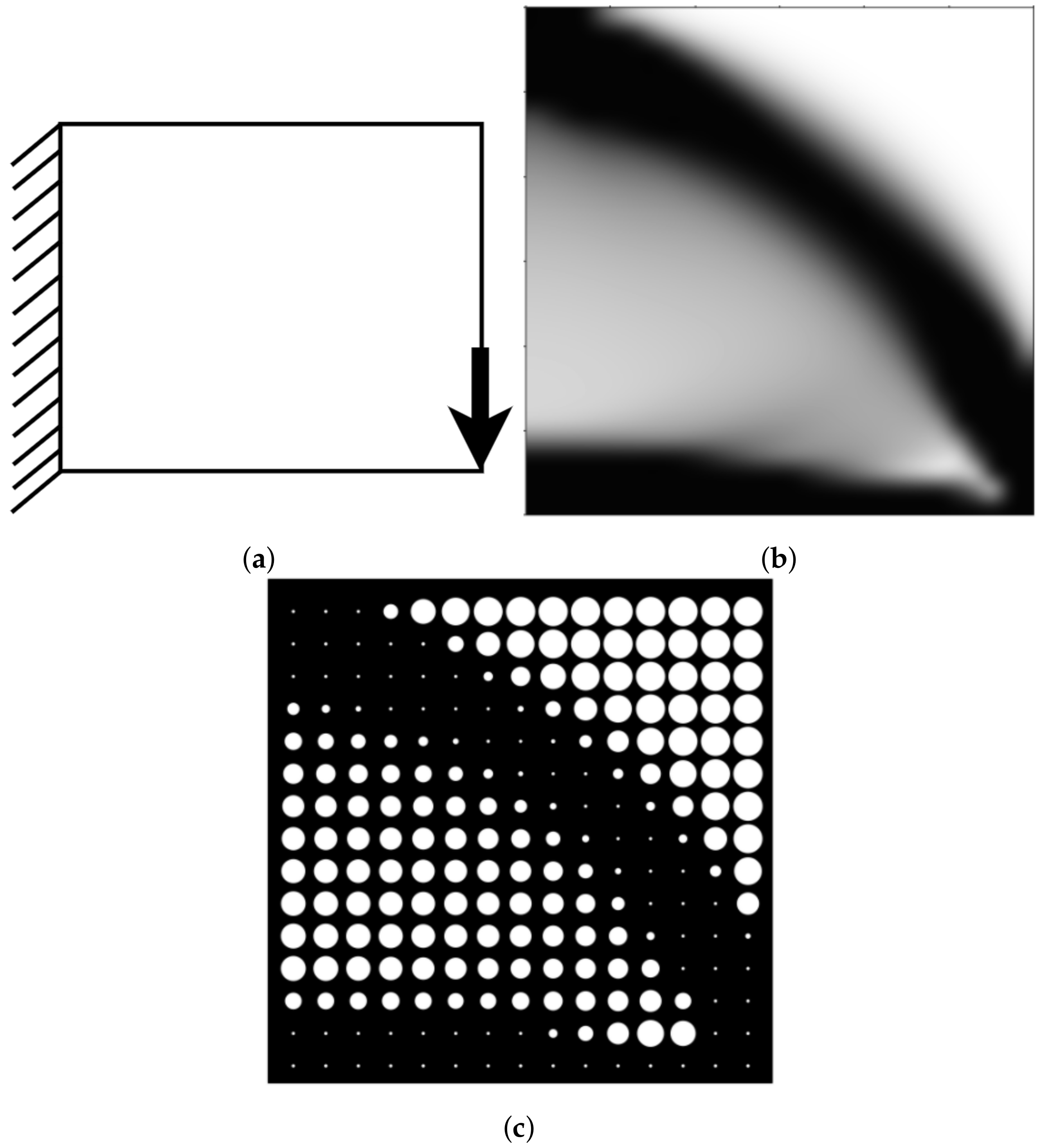
2.4.1. RVE Variation Based Boundary Information

Sometimes, the CS unit cells can vary based on the boundary of the design space; this is the case for conformal CSs. For conformal CSs, Tang et al.’s approach consists of using conformal CSs to create a lightweight structure [30]. There are different advantages in using conformal CSs, most importantly, the non-uniformity can potentially increase the strength of the CS.
Figure 10 shows the difference between a uniform and a conformal strut arrangement for a lattice structure. Other authors such as Nguyen et al. [31] have written about conformal CSs; they suggested a novel method of generating conformal CSs by offsetting the surfaces of the design space and dividing the result into tetrahedra. The same method had been used by Engelbrecht et al. [96]. Another interesting application of conformal CSs structures was showcased by Brennan-Craddock et al. [97]. The team used CSs for body protection and investigated their ability to absorb energy from the impact. The conclusion was that foams are suitable for energy absorption use. They defined four types of what they call conformal methods. In their framework, only the swept and the meshed structures correspond to the definition of conformal CSs. This framework is also used in this paper. As the name “conformal” implies, in the trimmed method the struts are cut at the boundaries. The “swept method” requires two surfaces, often parallel, in which unit cells are swept in the normal direction between the two surfaces. The mesh method is more robust as it does not require any specific surface configuration, nor does it require them to be parallel. The main disadvantage of the trimmed method is that unit cells near the boundary are weakened. To remedy that, the same authors have suggested wrapping a skin around the design space. Furthermore, Melpal [98] discussed a conformal CS technique in his PhD thesis; the technique consists of slicing design spaces (in STL format), taking some of the resulting intersection points and then generating conformal structures by offsetting the original design space [98]. An accurate example is given by Yang et al. [28]. Another example of the volume fraction varied between two boundaries is in the work by Plocher and Panesar [29]; a custom example of that case was made in Figure 11.

2.4.2. RVE Variation Based on Load Conditions

In the context of CSs, the designer typically deploys such architectures towards structural performance customization. One example is the use of CSs in the frame of structural topology optimization to balance lightweight and compliance requirements (see Figure 12).
When it comes to “load adaptive” cellular structures, the shape of the cellular structure wireframe is based on a response to loads applied on the surface. Chen [45] explains how space warping can be used to properly distribute the load. For example, in order to maximize strength, the CS will be deformed using a warping function. Another example is given by Reinhart and Teufelhart [50]. The authors developed a method that uses stress fields in order to create CSs. Robbins et al. [100] described an example of a multi-step optimization procedure where geometry is topologically optimized and then discretized using a hexahedral mesh. The mesh is then populated with unit cells.
A similar concept can be applied in other types of "loads". Another type of assumed “load” is permittivity for dielectric structures, as mentioned by Larimore et al. [47]. The idea is to create dielectric structures with spatially varying electromagnetic properties via AM. The unit RVE structures obtained by the researchers are made based on a curve wrapped within a rectangle. The curve is wrapped into multiple cells, such that when they are combined, they are able to change the permittivity of the cells by changing how dense the curve is wrapped at each of the cell’s locations (see Figure 13).
An example of stiffness maximization using lattice structure is given by Alzahrani et al. [11]. In their paper, they have redesigned a micro aerial vehicle, used for surveillance in hazardous areas. They have done so using a relative density mapping. Their technique consists of the following steps. First, they analyze the boundary conditions as well as the loads acting upon the vehicle. Then, they topologically optimize the part via the SIMP method. Afterward, they select the type of microstructure required. Finally, they fill each element on the part with a unit cell. The density of the element is what dictates the size of the unit cell struts. Furthermore, a minimum strut thickness can be imposed in order to properly fill every element. This addresses the problem of discontinuity in topologically optimized parts caused partially by elements with zero density.
The CS parameters (or implicitly the local RVE properties) can be changed in order to meet a specific optimization objective. One of those objectives is thermal applications. In the article written by Seepersad et al. [7], the authors show an example of a two-stage optimization of a CS. The first optimization is meant to reach certain customized structural properties and the second optimization to improve heat transfer without affecting the structural properties of the part. To do a multifunctional optimization, the typical force equation was replaced with the following: K · D = F + G , Where K is the global stiffness matrix for N elements stiffness matrices frame elements, D is the vector of global displacements, F is the vector of applied nodal loads and G is the vector of loads that account for thermal heating. The result has revealed itself to be promising toward structural and thermal multi-objective design optimization.
The article by Liu et al. [37] shows a rare example of varying the RVE (unit cells) using topology optimization results. The team has first constructed a unit-cell library in which they have analyzed the connectivity of the cell as well as some of their mathematical properties. In parallel, they have topologically optimized a structure and they have filled each element with a unit cell based on the density of the element. The volume fraction of the struts can then be optimized as well.

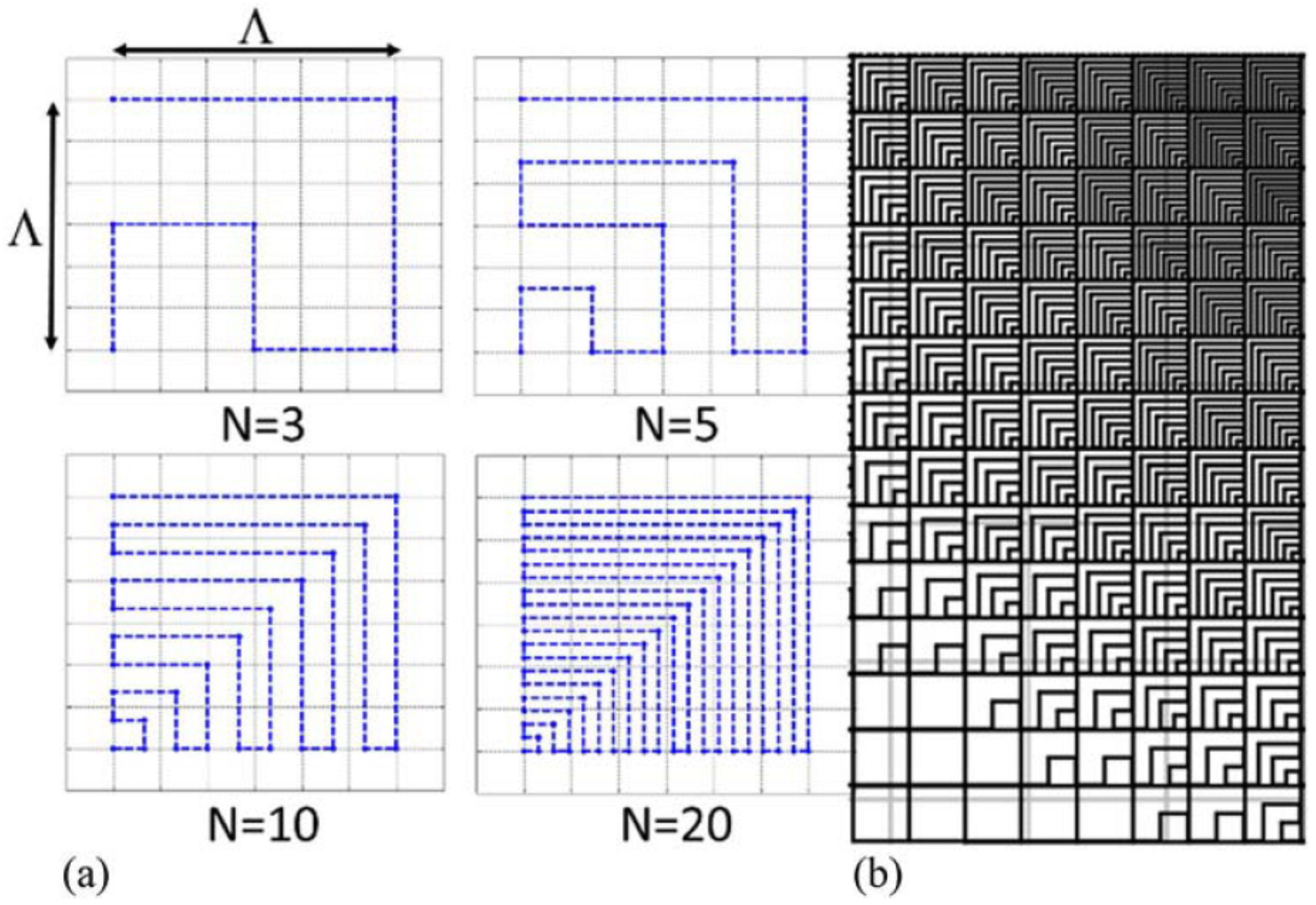
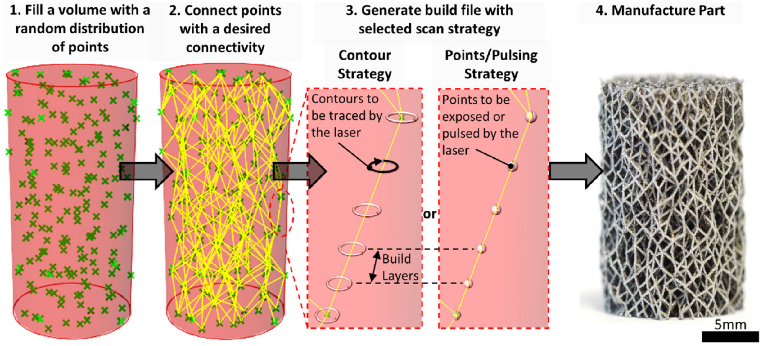
2.4.3. RVE Variation Based on Random and External Sources

Random and external sources are grouped together because they both have little to do with the geometry of the part, nor with what the part is going through. Many definitions have been given to randomized CSs; however, in this article, the following definition is given: a CS is called randomized if a designer goes through the process of designing a specific CS twice with the same inputs without any guarantee that the resulting structure will be exactly the same.
When generating a randomized CS, one might not be able to predict the exact layout of the material; however, it can be possible to approximately predict the stiffness of a randomized CS. This can be done through the global or localized control of porosity or conversely, density. An example can be shown in Figure 14. There are many applications of randomized CSs within the medical field, one of them is described by Fantini et al. [101]. The authors have developed a method to design biomimetic scaffolds using a Voronoi diagram. In the article, they describe an algorithm that takes as inputs the information from the scan of a patient’s bone, the desired porosity, and a target pore size. Then, based on the scattered points within a volume, the proposed algorithm creates Voronoi cells. The edges of the Voronoi cells are then thickened. The resulting CS will mimic the structure of the human bones. Their process is randomized because when generating the points or the seeds of the Voronoi cells, the user does not precisely control the location of those points but they can control the distribution or density of those points inside the design space. Similar work is done in Brackett et al. [51], where they use an error distribution method to map a Voronoi diagram to a grayscale image. Almonti et al. [54] have also proposed an approach for a completely customized structure using the Voronoi tessellation of a specific region to realize cellular structure typical of metal foams. In their case, the random change affects the topology of the cells.
In the work by Savio et al. [46], the authors have classified cellular structures for AM in the biomedical field; they have classified the conformal lattice in the pseudo-random category and Voronoi in the random category in a few instances. A Voronoi diagram is not necessarily a randomized CS, it all depends on how the seeds are generated, if the seeds have a fixed position then the Voronoi diagram will always be the same; hence, it cannot always be classified as random. The main difference with Voronoi diagrams is that the design variables are the seeds’ position and it is easier to generate random points than to directly generate randomly placed unit cells. In the latter case, one has to ensure connectivity, which is an issue that does not occur when working directly with a Voronoi diagram. According to Martínez et al. [102], the absence of a regular structure (for example, the stacking of more complex strut-based unit cells) affords for a simple approach to grade the foam geometry. To create randomized shapes, the vertices of existing unit cells can be varied in a random fashion, as is the case for Zhang et al. [61]’s work. A similar method is captured in the work of Reis et al. [62]. They create a network of struts that it subtracted from an original design space. This shows that sometimes, the unit cells are not the solid, but the voids.
Furthermore, the variations in a CS are not in response to a load nor to a boundary, but rather to an external source such as the CT scan of a part. For example, in the work by Cadman et al. [58], the authors have examined the microstructure of cuttlebone (bones of cuttle fish) and they have extracted properties such as the local volume fractions to try and reproduce the properties of the cuttlebone. Other sources that can induce a variation of unit cells often involved CT scans. The field of biomimicking contains a number of such examples.
As alluded to previously, the authors acknowledge that they can be multiple factors combined that result in RVE variations throughout a CS. For example, in the work by Tang and Zhao [103], the authors first used the boundary of the shapes to design a tetrahedral mesh and then, based on the stress within the part, they have been able to dictate the thickness of a strut. Similarly, the work by Martínez et al. [102] illustrates CS based on both random and load response. In this work, points (seeds) are scattered randomly, but the density of points follows a probability that is related to the level of localized stress within the parts.
Lim et al. [34] have used a tetrahedral mesh from FEA. Tetrahedral mesh vary based on the boundary of the structure. However, the authors have changed the way the density of strut is based on the stress level. Tetrahedral mesh is an example of boundary-induced cell transformation because the arrangement of the strut (the RVE in that case) is affected by the boundary of the shape.

2.5. CS Generation

This section will go over how one can generate and store CS digital information. There are many types of CS generation methods. However, only three of them will be discussed here: voxels, Constructive Solid Geometry (CSG), and implicit modeling.

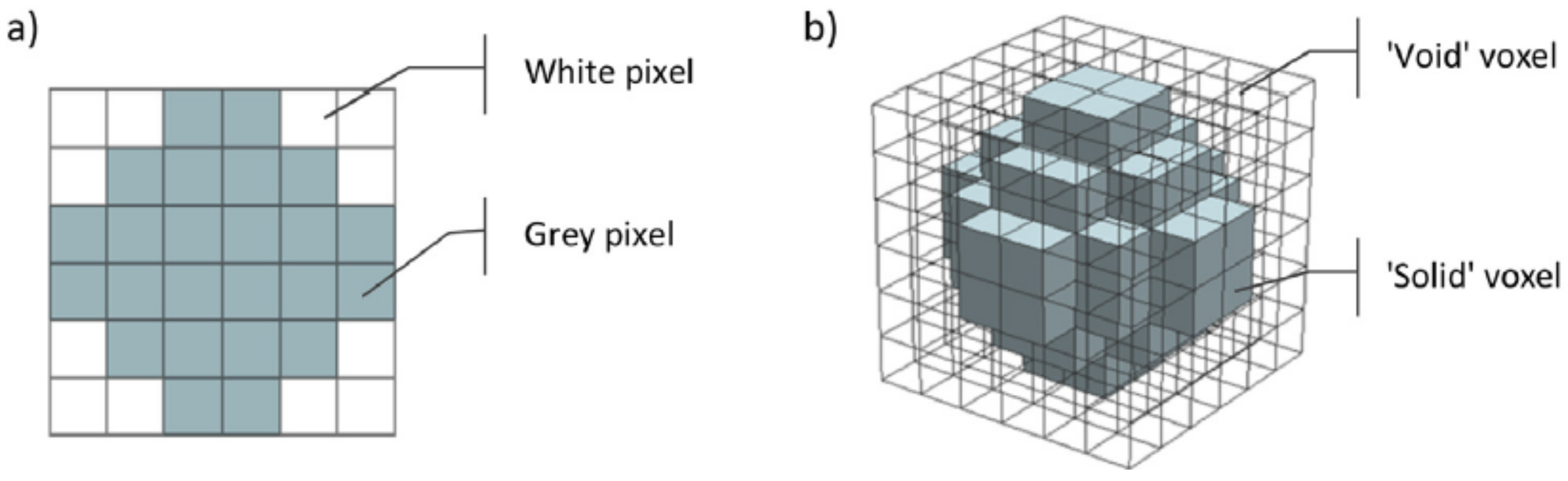
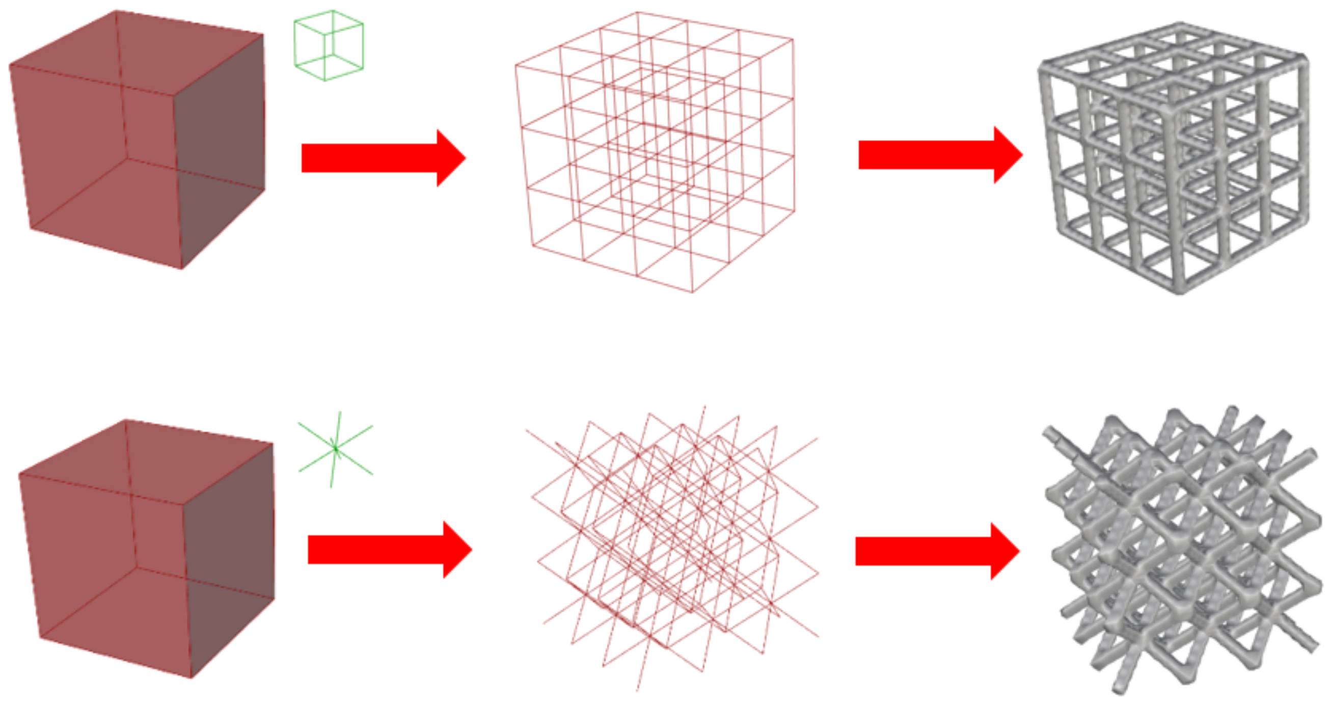
2.5.1. CS Generation via Voxel-Based Approaches

Generally, CSs are built by populating a design space with existing cells, as seen in Figure 1. Voxels are a relatively new concept, but an intuitive manner of representing solids. Each solid is created by adding small cubes in 3D (or voxels). The main disadvantage of this method is the computational cost, discretizing a shape accurately requires a high number of voxels [104].
As an example, in the work by Aremu et al. [104], the authors use voxels to generate CSs. The target geometry is first voxelized, as shown in Figure 15, then a grid was mapped onto the domain and trimmed, as shown in Figure 16. The main advantage of this method is that trimming and filling gaps becomes trivial when using a voxel representation. Unfortunately, the voxel representation cannot exactly represent any curved surface; therefore, staircases arise around such features. This problem can be minimized by using smaller voxels (i.e., higher resolution); however, this increases the computational cost. Another issue is that voxel representation is not well supported in the current CAD software and AM ecosystem. Most CAD software or AM build environments only accept geometry using Boundary REPresentation (BREP) or CSG. Unfortunately, the conversion from voxel to standard CAD file format nulls out the computational cost advantage of using voxels. When converting from voxel to mesh, the resulting STL file is extremely large as well [105].

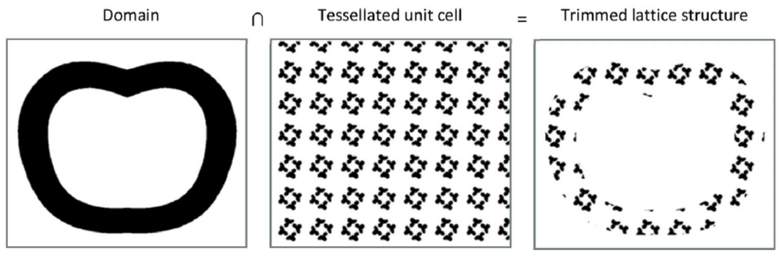
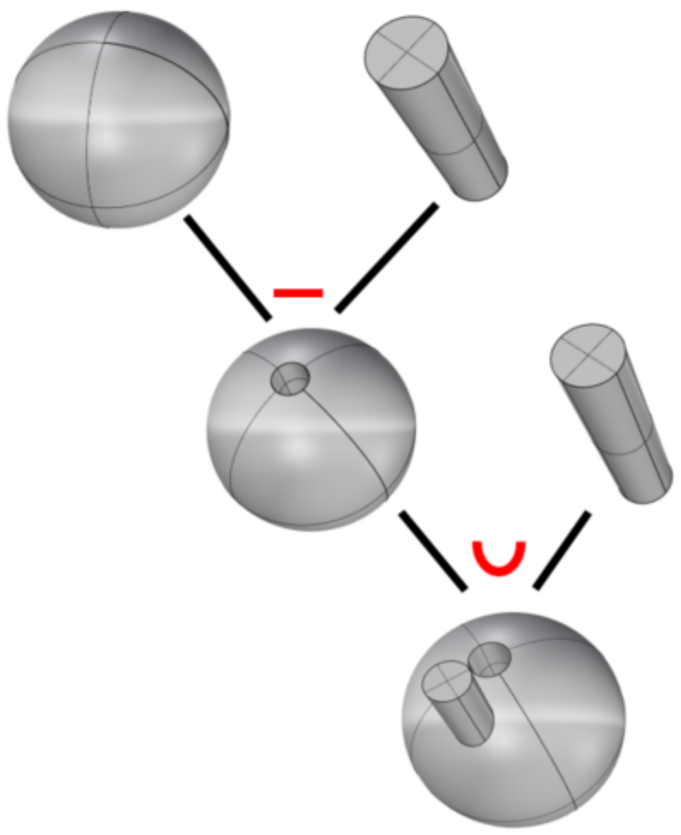
2.5.2. CS Generation via Constructive Solid Geometry

Constructive solid geometry (CSG) uses a sequential approach to represent a complex solid. CSG performs boolean operations on a set of primitives (cones, prisms, spheres) and stores the operations in a tree, as seen in Figure 17. A common method to represent a lattice structure using CSG is by creating CSs via representing the lines as cylinders and the nodes as spheres [4] and then joining them. Many problems arise from this method. First, the “join” operation can take a long time; this is because the only primitives that can be joined at once are the ones that are in contact. The second problem is the lack of smooth transition at the junction of the primitives. Eventually, when the structure is printed, the rough transition may result in stress concentrations. One simple way that has been found to overcome this challenge is to represent each node as a sphere where all the cylinder tips lie inside, as illustrated in Figure 18. Consequently, a boolean operation can be done to merge all cylinders and spheres into an RVE or a collection of RVEs into a more complex CS. Another way is to calculate the intersection between the cylinders and trim them such that they are flush with each other and then fill any gaps, as illustrated in Figure 19 [105,106].
In an effort to tackle the issue of nodes connection, Goel and Anand [42] have suggested using an additional unit cell. Overall, their methodology goes as follows: they perform topology optimization, then they use a mapping function, they then populate the space with Functional Gradient Lattice (FGL). The interesting part of their work is how they connect the different unit cells; they create a different unit cell to take care of the connection between the regular unit cells. That connection is made using B-spline principles, which comes in handy when the initial unit cells have different diameters.
The work of Zeinalabedini et al. [91] presents a method similar to Aremu et al. [104], where the authors resorted to subtracting a set of randomly spaced spheres from the design space to obtain the CS, as seen in Figure 20. In this methodology, the user can control the size of the spheres, and thus the overall porosity, as well as the overlap between spheres to control the degree of pore necking and inter-connectivity. In this particular case, the RVE is the void itself. Uhlířová and Pabst [107] have discussed a similar technique. There are two disadvantages to this approach. Firstly, there is a high computational cost of the boolean difference because the spheres are not necessarily overlapping, the number of subtractions that need to be done can be as high as the total number of spheres in the set. Secondly, the other drawback is the potential failure of such an operation; depending on the software used, subtracting two intersecting solids may not be possible. The main advantage of this is that it uses existing functions available in most CAD software; therefore, it is easy to implement for users with low experience.
Presently, most CAD software uses a combination of BREP and CSG [108] to capture the complexity of the CS design space and to visualize such structures. The BREP format describes geometry as a combination of vertices, edges, and faces [108], while in CSG, it is done through union, intersection, and difference of primitive solids (e.g., squares, spheres) [108].

2.5.3. CS Generation via Implicit Modeling and Mesh Data Structures

Solids can be represented by the volume enclosed within their representative surfaces. Such surfaces can be seen as the boundary between void and solid. To represent void and solid domains, numbers can be attributed to points within the design space volume, where the values of the points that are below a threshold value are seen as void while the ones above the threshold value are seen as solid. Two-dimensional examples of this concept can be seen in Figure 21). This procedure is known as level sets or implicit modeling. In order to create the contours in 3D, many algorithms can be used; one of the most famous is the marching cube algorithm [109]. This algorithm discretizes the surface with triangles and stores the coordinate of each vertex as a mesh. This process leads to meshes that can be exported as Standard Tessellation Language (STL) files, which can be used to visualize structures.
One advantage of this method is that it allows a smooth transition between the primitives without the need for fillets, as seen in Figure 22. The other advantage of such a method is that the computational cost is mainly affected by the density of the points’ grid. The number of operations done on the grid to change the value at each point also affects the computational cost; however, some could argue that an intricate CS will require a highly dense grid, which will greatly increase the computational cost.
Researchers such as Tang et al. [110] have done some work towards helping to improve solid modeling of lattice structures. To do so, they have designed a hybrid approach, where the method first starts by designing and generating the lattice frame, then implicit functions are used to thicken the frame. The final structure is then voxelized such that it can be directly used for AM. Similarly, strut-based unit cells can be thickened using implicit functions. An example of this generation method is given by Intralattice [82], a plug-in for the Rhinoceros3D CAD software. In this platform, the unit cell is first defined and then replicated in the design space periodically or pseudo-periodically. Finally, the resulting wireframes are thickened, as seen in Figure 23.
Triply Periodic Minimized Structures (TPMS) are examples of structures that are implemented using implicit modeling. Some algorithms, such as highlighted by Hsieh and Valdevit [111] have used implicit functions to represent triply periodic minimum surfaces. In the article by Kumar et al. [92], structures were also built using implicit modeling. In the article by Yang et al. [55], an example is shown of the transition that can be made between the primitives. Furthermore, as topology optimization can also be done using level sets; it is only a matter of time before TOMs can be rendered using implicit functions. In other occasions, meshes that already exist can be modified using known mesh operations. In Savio et al. [46]’s work, an FE model is first built based on loads and the surface is subdivided using computer graphic techniques. Researchers such as Stadlbauer et al. [112] have worked on an approach to interactively generate cellular structures on existing meshes. With surface meshes as inputs, they can decompose their meshes into hollow cellular structures that act as a skeleton on the surface and a set of thin shells. Liang et al. [113] have given an example of a lattice structure that is built using implicit functions. The values of the grid points are given based on the distance to the closest point on the lattice core (skeleton).
For digital storage and handling of the resulting geometry, the de facto standard in AM is the STL file. With the advent of multi-material printers and the increasing complexity of additive manufactured parts, the STL format is starting to become limiting, mainly in its inability to store other types of information (such as materials, colors, copyrights), in addition to geometry data. New file formats (3MF and AMF) were created to address such shortcomings. Both 3MF and AMF are XML (extensible markup language)-based, which enables them to store other information in addition to geometry. In the 3MF and AMF file, geometry is still stored as a mesh. In AMF, a porous structure can be specified as a material. On the other hand, 3MF now supports the representation of CSs as a set of beam elements. Since file formats store geometry information as a surface, most of the algorithms described in the previous sections aim at obtaining a mesh-based representation of CSs. Here lies the challenge in generating cellular structures; as the complexity of CSs increases, the complexity of the mesh needed to describe it increases exponentially [27]. This drives the computation time and file size upward when processing and generating CSs. The complexity of CS also pushes CAD technology to the limit. Representing large numbers of features using BREP and CSG becomes impractical [104]. Hence, there is a continued interest in representing and generating CSs either as beam elements, implicit models or voxels.

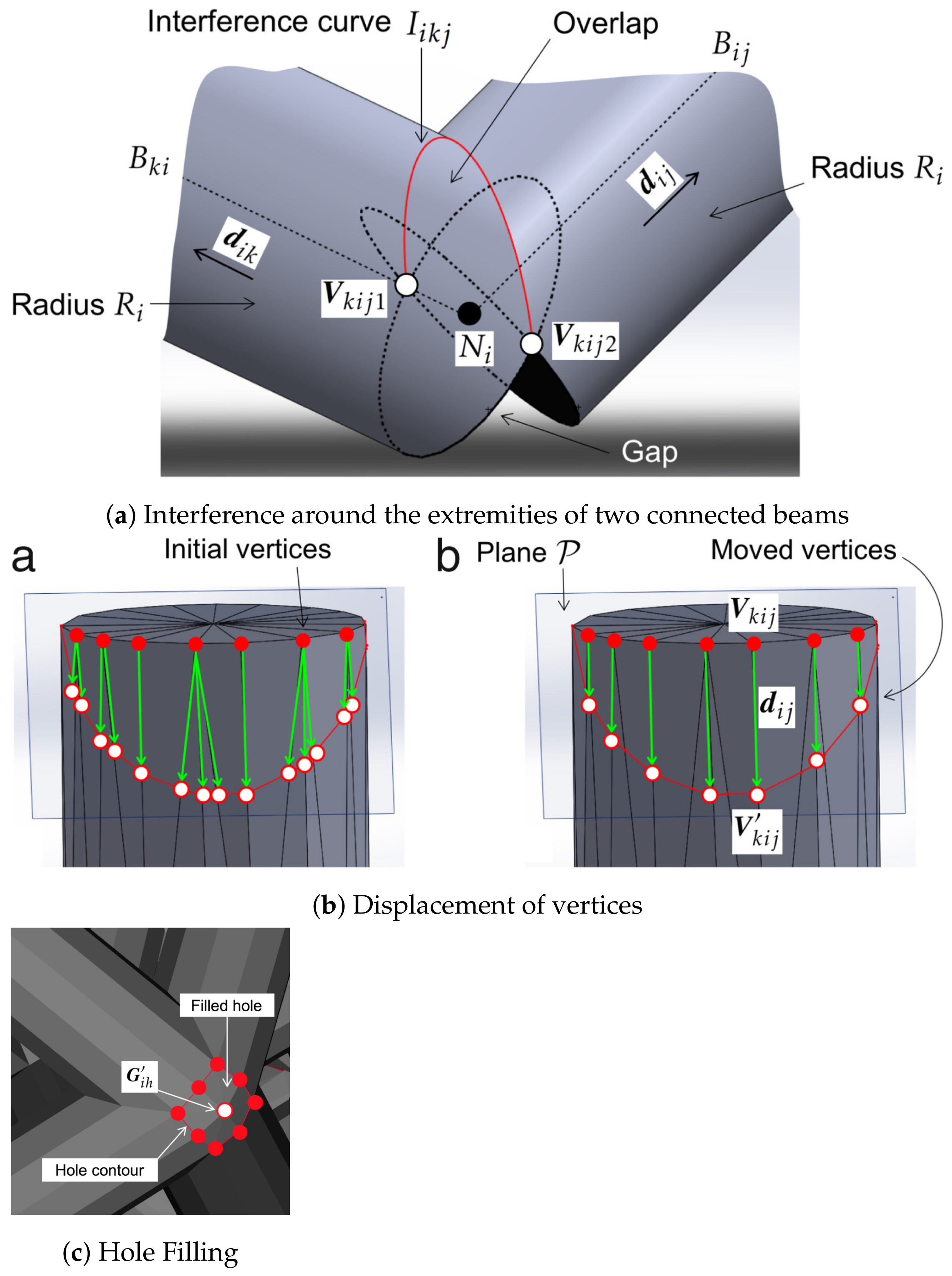
3. Highlights of Manufacturability Challenges of Cellular Structures

One of the main challenges in AM is that the manufacturability of components is at the intersection of the design space, material properties and process physics, where the interactions are not fully understood. Furthermore, the effect of the process parameters on the manufacturability of lattices depends on the AM technique used. This section presents the set of design limitations relevant to each technology.
The parameters that affect manufacturability can be divided into two categories: the lattice design parameters and parameters related to the AM process. For the lattice design, this includes the size of the RVEs (unit cells) and the primitive properties (the strut angles and diameters), which is typically be dictated based on the resolution of the AM technology (design guidelines) and experience with each material and machine (design rules). For AM parameters, each technology has a specific set of inputs; such brief examples are the scanning speed, in the case of powder bed processes, or the extrusion speed in the case of material extrusion processes. In the context of this work, manufacturability refers to the capacity to achieve three things: dimensional fidelity, low surface roughness, and low porosity defects. It is important to have a firm understanding of those elements to be able to determine how the mechanical properties, among others, will be affected. Table 2 summarizes the various design constraints with example works across the more common AM fabrication techniques [114]. Mechanical properties will not be explored in this context since such properties are dependent on the material used.
One design limitation is the need to remove unused material from inside the lattice structure. For the powder bed AM process such as Laser Powder Bed Fusion (LPBF) or Selective Laser Melting (SLM), Selective Laser Sintering (SLS), Binder Jetting (BJ), and Electron Beam (EBM) powder bed fusion, the lattice inner voids need to be large enough to allow powder to flow freely and to exit the volume during de-powdering. Adam and Zimmer [115] mention a minimum size requirement for SLM and SLS, although such requirement is likely dependent on the powder size distribution and material rheological properties. For stereolithography (SLA), the unused resin flows freely out and only requires an exit opening if the lattice is fully enclosed. For Fused Deposition Modeling (FDM) and Material Jetting (MJ), internal material removal requirements are largely driven by the need to remove support structures via mechanical or chemical processes, if such support structures are present.
If the lattice structures contain overhangs as defined by a technology class-specific threshold angle, the overhanging features need to be supported through the generation of expendable support structures. This can be mitigated either by changing the lattice design, or by modifying the build orientation of the product. For multi-material capable systems like FDM or MJ, support structures can be printed out of dissolvable materials. For FDM, all overhang needs to be supported due to gravity. Adam and Zimmer [115] and Qattawi et al. [116] illustrate a few design rules for FDM. Support structures are also necessary for LPBF and EBM. For LPBF, support structures act as thermal dissipation structures, to prevent warping and material vaporization due to the accumulation of residual stress and thermal insulating properties of powders [117], respectively. Adam and Zimmer [115] and Kranz et al. [118] show a few design guidelines regarding overhangs and slopes for LPBF. For EBM, support structures are technically only necessary for anchoring components to the build plate, as the powder around the part is sintered by the process into a powder cake. The powder cake provides enough mechanical support and heat dissipation properties for the object [117]. For SLS and BJ, support structures are generally not necessary for overhangs, as the powder provides enough gravity support [115,117]. Furthermore, such processes do not experience excessive thermal gradients. For SLA, although not robustly documented in literature, design guidelines by 3D Hubs and Materialise specify that support structures are only needed to anchor the object to the build plate and ensure print object continuity in respect to the build plate [119,120].
Another design limitation stems from the material–process–design relationship, where the minimum feature size of an RVE correlates with the resulting porous defects in the CS. For LPBF and EBM, the dimension of the energy source, the powder size and the minimum desired feature size in an RVE, as well as the surrounding RVE neighbors result in a complex set of melt pool and heat transfer phenomena. Such interplay can often result in pore defects; the mechanism of pore formation, the classification of pores, and strategies to mitigate such defects in powder bed fusion processes have been reviewed and summarized by Echeta et al. [121] and Sola and Nouri [122]. For BJ technologies, the scale of the interaction between the layer resolution, the liquid binder droplets, and the powder morphology and size can pose limitations in terms of the lattice structure geometric and green density quality [123]; such qualities are also impacted by the sintering and densification process. For SLA, pore defects are only mentioned when printing ceramic-loaded polymers into complex-shaped objects, where the pores are mainly created by the sintering post-processing steps rather than the AM process itself [124]. As for FDM, the minimum feature size of an RVE and the nozzle diameter play a role in pore defect generation. The RVE inner features may be inadequately filled due to discontinuity in the toolpath and gaps between the extruded plastic filament [125]. For MJ, pore defects are not mentioned [126] except in the context of polymer-loaded ceramic production [127].

4. Conclusions

The advent of AM has expanded the horizons of cellular structure design. In this paper, a new cellular structures classification paradigm has been developed. The design methods for cellular structures have been classified by identifying all the geometric degrees of freedom that are involved in the construction of cellular structures. The classification was brought forth by reviewing the numerous case studies, with representative works highlighted. Moreover, cellular structure generation and CAD manipulation techniques have also been reviewed. The review explored the different design constraints imposed by AM processes on the quality of cellular structures. Finally, manufacturability issues that occur when printing CSs are also highlighted. In the future, more work is needed to develop new simulation methods and design tools for CSs, to also analyze the printing parameters that have an effect on the dimensional accuracy and the properties (mechanical, thermal, etc.) of CSs, to then establish CS design rules that should be implemented at the design stage.

Author Contributions

Cellular structure design classification, overview of representative volume elements, RVE variation methods, RVE variation factors, K.M.N.; CS generation, K.M.N., M.W.; highlights of manufacturability challenges of cellular structures, M.W.; conceptualization, supervision and correction, M.V. All authors have read and agreed to the published version of the manuscript.

Funding

The authors appreciate the funding support from the Federal Economic Development Agency for Southern Ontario (FedDev Ontario) grant number 814654.

Institutional Review Board Statement

Not applicable.

Informed Consent Statement

Not applicable.

Data Availability Statement

Not applicable.

Conflicts of Interest

The authors declare no conflict of interest.

Abbreviations

The following abbreviations are used in this manuscript:
AMAdditive manufacturing
BEMBoundary element method
BESOBi-directional evolutionary structural optimization
BJBinder Jetting
CADComputer Aided Design
CpTiCommercially pure titanium
CSCellular structure
CSGConstructive solid geometry
EBMElectron beam melting
ESOEvolutionary structural optimization
FDMFused deposition modeling
FEAFinite element analysis
FFFFused filament fabrication
FGMFunctionally graded material
GDoFGeometrical degrees of freedom
GLSGradient lattice structures
HIPHot isostatic pressure
LPBFLaser powder bed fusion
MJMaterial Jetting
SIMPSolid isotropic material with penalization method
SLAStereolithography
SLSSelective laser sintering
STLStandard Tessellation Language

References

  1. Huynh, L.; Rotella, J.; Sangid, M.D. Fatigue behavior of IN718 microtrusses produced via additive manufacturing. Mater. Des. 2016, 105, 278–289. [Google Scholar] [CrossRef]
  2. Ozdemir, Z.; Hernandez-Nava, E.; Tyas, A.; Warren, J.A.; Fay, S.D.; Goodall, R.; Todd, I.; Askes, H. Energy absorption in lattice structures in dynamics: Experiments. Int. J. Impact Eng. 2016, 89, 49–61. [Google Scholar] [CrossRef] [Green Version]
  3. Shamvedi, D.; McCarthy, O.J.; Donoghue, E.O.; Danilenkoff, C.; OLeary, P.; Raghavendra, R. 3D Metal printed heat sinks with longitudinally varying lattice structure sizes using direct metal laser sintering. Virtual Phys. Prototyp. 2018, 13, 301–310. [Google Scholar] [CrossRef]
  4. Syam, W.P.; Jianwei, W.; Zhao, B.; Maskery, I.; Elmadih, W.; Leach, R. Design and analysis of strut-based lattice structures for vibration isolation. Precis. Eng. 2018, 52, 494–506. [Google Scholar] [CrossRef]
  5. Zhang, X.; Xia, Y.; Wang, J.; Yang, Z.; Tu, C.; Wang, W. Medial axis tree—An internal supporting structure for 3D printing. Comput. Aided Geom. Des. 2015, 35, 149–162. [Google Scholar] [CrossRef]
  6. Mazur, M.; Leary, M.; Sun, S.; Vcelka, M.; Shidid, D.; Brandt, M. Deformation and failure behaviour of Ti-6Al-4V lattice structures manufactured by selective laser melting (SLM). Int. J. Adv. Manuf. Technol. 2016, 84, 1391–1411. [Google Scholar] [CrossRef]
  7. Seepersad, C.C.; Allen, J.K.; McDowell, D.L.; Mistree, F. Multifunctional topology design of cellular material structures. J. Mech. Des. 2008, 130, 031404. [Google Scholar] [CrossRef]
  8. Chu, C.; Graf, G.; Rosen, D.W. Design for additive manufacturing of cellular structures. Comput. Aided Des. Appl. 2008, 5, 686–696. [Google Scholar] [CrossRef] [Green Version]
  9. Wang, B.; Wu, L.; Ma, L.; Sun, Y.; Du, S. Mechanical behavior of the sandwich structures with carbon fiber-reinforced pyramidal lattice truss core. Mater. Des. (1980–2015) 2010, 31, 2659–2663. [Google Scholar] [CrossRef]
  10. Kooistra, G.W.; Wadley, H.N. Lattice truss structures from expanded metal sheet. Mater. Des. 2007, 28, 507–514. [Google Scholar] [CrossRef]
  11. Alzahrani, M.; Choi, S.K.; Rosen, D.W. Design of truss-like cellular structures using relative density mapping method. Mater. Des. 2015, 85, 349–360. [Google Scholar] [CrossRef] [Green Version]
  12. Wang, Y.; Chen, F.; Wang, M.Y. Concurrent design with connectable graded microstructures. Comput. Methods Appl. Mech. Eng. 2017, 317, 84–101. [Google Scholar] [CrossRef]
  13. Panesar, A.; Abdi, M.; Hickman, D.; Ashcroft, I. Strategies for functionally graded lattice structures derived using topology optimisation for additive manufacturing. Addit. Manuf. 2018, 19, 81–94. [Google Scholar] [CrossRef]
  14. Dong, G.; Tang, Y.; Zhao, Y.F. A survey of modeling of lattice structures fabricated by additive manufacturing. J. Mech. Des. 2017, 139, 100906. [Google Scholar] [CrossRef]
  15. Helou, M.; Kara, S. Design, analysis and manufacturing of lattice structures: An overview. Int. J. Comput. Integr. Manuf. 2018, 31, 243–261. [Google Scholar] [CrossRef]
  16. Schaedler, T.A.; Carter, W.B. Architected cellular materials. Annu. Rev. Mater. Res. 2016, 46, 187–210. [Google Scholar] [CrossRef]
  17. Plocher, J.; Panesar, A. Review on design and structural optimisation in additive manufacturing: Towards next-generation lightweight structures. Mater. Des. 2019, 183, 108164. [Google Scholar] [CrossRef]
  18. Nagesha, B.; Dhinakaran, V.; Shree, M.V.; Kumar, K.M.; Chalawadi, D.; Sathish, T. Review on characterization and impacts of the lattice structure in additive manufacturing. Mater. Today Proc. 2020, 21, 916–919. [Google Scholar] [CrossRef]
  19. Tamburrino, F.; Graziosi, S.; Bordegoni, M. The design process of additively manufactured mesoscale lattice structures: A review. J. Comput. Inf. Sci. Eng. 2018, 18. [Google Scholar] [CrossRef]
  20. Qin, Y.; Wen, P.; Guo, H.; Xia, D.; Zheng, Y.; Jauer, L.; Poprawe, R.; Voshage, M.; Schleifenbaum, J.H. Additive manufacturing of biodegradable metals: Current research status and future perspectives. Acta Biomater. 2019, 98, 3–22. [Google Scholar] [CrossRef]
  21. Du Plessis, A.; Broeckhoven, C.; Yadroitsava, I.; Yadroitsev, I.; Hands, C.H.; Kunju, R.; Bhate, D. Beautiful and functional: A review of biomimetic design in additive manufacturing. Addit. Manuf. 2019, 27, 408–427. [Google Scholar] [CrossRef]
  22. Yuan, L.; Ding, S.; Wen, C. Additive manufacturing technology for porous metal implant applications and triple minimal surface structures: A review. Bioact. Mater. 2019, 4, 56–70. [Google Scholar] [CrossRef] [PubMed]
  23. Zhang, C.; Chen, F.; Huang, Z.; Jia, M.; Chen, G.; Ye, Y.; Lin, Y.; Liu, W.; Chen, B.; Shen, Q.; et al. Additive manufacturing of functionally graded materials: A review. Mater. Sci. Eng. A 2019, 764, 138209. [Google Scholar] [CrossRef]
  24. Seharing, A.; Azman, A.H.; Abdullah, S. A review on integration of lightweight gradient lattice structures in additive manufacturing parts. Adv. Mech. Eng. 2020, 12, 1687814020916951. [Google Scholar] [CrossRef]
  25. Nazir, A.; Abate, K.M.; Kumar, A.; Jeng, J.Y. A state-of-the-art review on types, design, optimization, and additive manufacturing of cellular structures. Int. J. Adv. Manuf. Technol. 2019, 104, 3489–3510. [Google Scholar] [CrossRef]
  26. Tang, Y.; Zhao, Y.F. A survey of the design methods for additive manufacturing to improve functional performance. Rapid Prototyp. J. 2016, 22, 569–590. [Google Scholar] [CrossRef]
  27. Hadi, A.; Vignat, F.; Villeneuve, F. Design configurations and creation of lattice structures for metallic additive manufacturing. In Proceedings of the 14ème Colloque National AIP PRIMECA, La Plagne, France, 31 March–2 April 2015. [Google Scholar]
  28. Yang, N.; Quan, Z.; Zhang, D.; Tian, Y. Multi-morphology transition hybridization CAD design of minimal surface porous structures for use in tissue engineering. Comput. Aided Des. 2014, 56, 11–21. [Google Scholar] [CrossRef]
  29. Plocher, J.; Panesar, A. Effect of density and unit cell size grading on the stiffness and energy absorption of short fibre-reinforced functionally graded lattice structures. Addit. Manuf. 2020, 101171. [Google Scholar] [CrossRef]
  30. Tang, Y.; Yang, S.; Zhao, Y.F. Design Method for Conformal Lattice-Skin Structure Fabricated by AM Technologies. In Proceedings of the ASME 2016 International Design Engineering Technical Conferences and Computers and Information in Engineering Conference, Charlotte, NC, USA, 21–24 August 2016; p. V01AT02A037. [Google Scholar]
  31. Nguyen, J.; Park, S.I.; Rosen, D.W.; Folgar, L.; Williams, J. Conformal lattice structure design and fabrication. In Proceedings of the Solid Freeform Fabrication Symposium (SFF), Austin, TX, USA, 6–8 August 2012; pp. 6–8. [Google Scholar]
  32. Terriault, P.; Brailovski, V. Modeling and simulation of large, conformal, porosity-graded and lightweight lattice structures made by additive manufacturing. Finite Elem. Anal. Des. 2018, 138, 1–11. [Google Scholar] [CrossRef]
  33. Wang, Y.; Zhang, L.; Daynes, S.; Zhang, H.; Feih, S.; Wang, M.Y. Design of graded lattice structure with optimized mesostructures for additive manufacturing. Mater. Des. 2018, 142, 114–123. [Google Scholar] [CrossRef]
  34. Lim, Y.E.; Park, J.H.; Park, K. Automatic design of 3D conformal lightweight structures based on a tetrahedral mesh. Int. J. Precis. Eng. Manuf. Green Technol. 2018, 5, 499–506. [Google Scholar] [CrossRef]
  35. Guo, Y.; Liu, K.; Yu, Z. Tetrahedron-Based Porous Scaffold Design for 3D Printing. Designs 2019, 3, 16. [Google Scholar] [CrossRef] [Green Version]
  36. Ambu, R.; Morabito, A.E. Porous scaffold design based on minimal surfaces: Development and assessment of variable architectures. Symmetry 2018, 10, 361. [Google Scholar] [CrossRef] [Green Version]
  37. Liu, Y.; Zhuo, S.; Xiao, Y.; Zheng, G.; Dong, G.; Zhao, Y.F. Rapid modeling and design optimization of multi-topology lattice structure based on unit-cell library. J. Mech. Des. 2020, 142. [Google Scholar] [CrossRef]
  38. Daynes, S.; Feih, S.; Lu, W.F.; Wei, J. Optimisation of functionally graded lattice structures using isostatic lines. Mater. Des. 2017, 127, 215–223. [Google Scholar] [CrossRef]
  39. Smith, C.J.; Gilbert, M.; Todd, I.; Derguti, F. Application of layout optimization to the design of additively manufactured metallic components. Struct. Multidiscip. Optim. 2016, 54, 1297–1313. [Google Scholar] [CrossRef] [Green Version]
  40. Teufelhart, S.; Reinhart, G. Optimization of strut diameters in lattice structures. In Proceedings of the 23th Annual Solid Freeform Fabrication Symposium, Austin, TX, USA, 6–8 August 2012; pp. 719–733. [Google Scholar]
  41. Cheng, L.; Liu, J.; To, A.C. Concurrent lattice infill with feature evolution optimization for additive manufactured heat conduction design. Struct. Multidiscip. Optim. 2018, 1–25. [Google Scholar] [CrossRef]
  42. Goel, A.; Anand, S. Design of functionally graded lattice structures using B-splines for additive manufacturing. Procedia Manuf. 2019, 34, 655–665. [Google Scholar] [CrossRef]
  43. Zhang, P.; Toman, J.; Yu, Y.; Biyikli, E.; Kirca, M.; Chmielus, M.; To, A.C. Efficient design-optimization of variable-density hexagonal cellular structure by additive manufacturing: Theory and validation. J. Manuf. Sci. Eng. 2015, 137, 021004. [Google Scholar] [CrossRef]
  44. Nguyen, C.H.P.; Kim, Y.; Choi, Y. Design for additive manufacturing of functionally graded lattice structures: A design method with process induced anisotropy consideration. Int. J. Precis. Eng. Manuf. Green Technol. 2019, 1–17. [Google Scholar] [CrossRef]
  45. Chen, Y. 3D texture mapping for rapid manufacturing. Comput. Aided Des. Appl. 2007, 4, 761–771. [Google Scholar] [CrossRef] [Green Version]
  46. Savio, G.; Meneghello, R.; Concheri, G. Geometric modeling of lattice structures for additive manufacturing. Rapid Prototyp. J. 2018. [Google Scholar] [CrossRef]
  47. Larimore, Z.; Jensen, S.; Parsons, P.; Good, B.; Smith, K.; Mirotznik, M. Use of space-filling curves for additive manufacturing of three dimensionally varying graded dielectric structures using fused deposition modeling. Addit. Manuf. 2017, 15, 48–56. [Google Scholar] [CrossRef] [Green Version]
  48. Song, G.H.; Jing, S.K.; Zhao, F.L.; Wang, Y.D.; Xing, H.; Qie, L.F. Design of Lattice Structures Using Local Relative Density Mapping Method. Chin. J. Mech. Eng. 2018, 31, 89. [Google Scholar] [CrossRef] [Green Version]
  49. Li, D.; Liao, W.; Dai, N.; Dong, G.; Tang, Y.; Xie, Y.M. Optimal design and modeling of gyroid-based functionally graded cellular structures for additive manufacturing. Comput. Aided Des. 2018, 104, 87–99. [Google Scholar] [CrossRef]
  50. Reinhart, G.; Teufelhart, S. Optimization of mechanical loaded lattice structures by orientating their struts along the flux of force. Procedia CIRP 2013, 12, 175–180. [Google Scholar] [CrossRef]
  51. Brackett, D.; Ashcroft, I.; Wildman, R.; Hague, R.J. An error diffusion based method to generate functionally graded cellular structures. Comput. Struct. 2014, 138, 102–111. [Google Scholar] [CrossRef]
  52. Opgenoord, M.M.; Willcox, K.E. Design for additive manufacturing: Cellular structures in early-stage aerospace design. Struct. Multidiscip. Optim. 2019, 60, 411–428. [Google Scholar] [CrossRef]
  53. Rodríguez-Montaño, Ó.L.; Cortés-Rodríguez, C.J.; Naddeo, F.; Uva, A.E.; Fiorentino, M.; Naddeo, A.; Cappetti, N.; Gattullo, M.; Monno, G.; Boccaccio, A. Irregular Load Adapted Scaffold Optimization: A Computational Framework Based on Mechanobiological Criteria. ACS Biomater. Sci. Eng. 2019, 5, 5392–5411. [Google Scholar] [CrossRef]
  54. Almonti, D.; Baiocco, G.; Tagliaferri, V.; Ucciardello, N. Design and Mechanical Characterization of Voronoi Structures Manufactured by Indirect Additive Manufacturing. Materials 2020, 13, 1085. [Google Scholar] [CrossRef] [PubMed] [Green Version]
  55. Yang, N.; Du, C.f.; Wang, S.; Yang, Y.; Zhang, C. Mathematically defined gradient porous materials. Mater. Lett. 2016, 173, 136–140. [Google Scholar] [CrossRef]
  56. Jin, Y.; Kong, H.; Zhou, X.; Li, G.; Du, J. Design and Characterization of Sheet-Based Gyroid Porous Structures with Bioinspired Functional Gradients. Materials 2020, 13, 3844. [Google Scholar] [CrossRef] [PubMed]
  57. Niknam, H.; Akbarzadeh, A. Graded lattice structures: Simultaneous enhancement in stiffness and energy absorption. Mater. Des. 2020, 196, 109129. [Google Scholar] [CrossRef]
  58. Cadman, J.; Zhou, S.; Chen, Y.; Li, W.; Appleyard, R.; Li, Q. Characterization of cuttlebone for a biomimetic design of cellular structures. Acta Mech. Sin. 2010, 26, 27–35. [Google Scholar] [CrossRef]
  59. Mullen, L.; Stamp, R.C.; Fox, P.; Jones, E.; Ngo, C.; Sutcliffe, C.J. Selective laser melting: A unit cell approach for the manufacture of porous, titanium, bone in-growth constructs, suitable for orthopedic applications. II. Randomized structures. J. Biomed. Mater. Res. Part Appl. Biomater. Off. J. Soc. Biomater. Jpn. Soc. Biomater. Aust. Soc. Biomater. Korean Soc. Biomater. 2010, 92, 178–188. [Google Scholar] [CrossRef]
  60. Liu, F.; Mao, Z.; Zhang, P.; Zhang, D.Z.; Jiang, J.; Ma, Z. Functionally graded porous scaffolds in multiple patterns: New design method, physical and mechanical properties. Mater. Des. 2018, 160, 849–860. [Google Scholar] [CrossRef]
  61. Zhang, Z.; Yuan, L.; Lee, P.D.; Jones, E.; Jones, J.R. Modeling of time dependent localized flow shear stress and its impact on cellular growth within additive manufactured titanium implants. J. Biomed. Mater. Res. Part Appl. Biomater. 2014, 102, 1689–1699. [Google Scholar] [CrossRef] [Green Version]
  62. Reis, S.; Vasconcelos, V.; Leite, M.; Vasconcelos, W. Development of a Computer Application to Simulate Porous Structures. Mater. Res. 2002, 5, 275–279. [Google Scholar] [CrossRef]
  63. Ghouse, S.; Babu, S.; Nai, K.; Hooper, P.A.; Jeffers, J.R. The influence of laser parameters, scanning strategies and material on the fatigue strength of a stochastic porous structure. Addit. Manuf. 2018, 22, 290–301. [Google Scholar] [CrossRef]
  64. Liu, F.; Ran, Q.; Zhao, M.; Zhang, T.; Zhang, D.Z.; Su, Z. Additively manufactured continuous cell-size gradient porous scaffolds: Pore characteristics, mechanical properties and biological responses in vitro. Materials 2020, 13, 2589. [Google Scholar] [CrossRef]
  65. Cuan-Urquizo, E.; Martínez-Magallanes, M.; Crespo-Sánchez, S.E.; Gómez-Espinosa, A.; Olvera-Silva, O.; Roman-Flores, A. Additive manufacturing and mechanical properties of lattice-curved structures. Rapid Prototyp. J. 2019. [Google Scholar] [CrossRef]
  66. Yang, L.; Harrysson, O.; Cormier, D.; West, H.; Gong, H.; Stucker, B. Additive manufacturing of metal cellular structures: Design and fabrication. JOM 2015, 67, 608–615. [Google Scholar] [CrossRef]
  67. Beyer, C.; Figueroa, D. Design and analysis of lattice structures for additive manufacturing. J. Manuf. Sci. Eng. 2016, 138, 121014. [Google Scholar] [CrossRef]
  68. Du Plessis, A.; Yadroitsava, I.; Yadroitsev, I. Ti6Al4V lightweight lattice structures manufactured by laser powder bed fusion for load-bearing applications. Opt. Laser Technol. 2018, 108, 521–528. [Google Scholar] [CrossRef]
  69. Ongaro, F. Estimation of the effective properties of two-dimensional cellular materials: A review. Theor. Appl. Mech. Lett. 2018, 8, 209–230. [Google Scholar] [CrossRef]
  70. Rehme, O.; Emmelmann, C. Selective laser melting of honeycombs with negative Poissonś ratio. J. Laser Micro Nanoeng 2009, 4, 128–134. [Google Scholar] [CrossRef]
  71. Yan, C.; Hao, L.; Hussein, A.; Young, P. Ti–6Al–4V triply periodic minimal surface structures for bone implants fabricated via selective laser melting. J. Mech. Behav. Biomed. Mater. 2015, 51, 61–73. [Google Scholar] [CrossRef] [PubMed] [Green Version]
  72. Yan, C.; Hao, L.; Hussein, A.; Young, P.; Raymont, D. Advanced lightweight 316L stainless steel cellular lattice structures fabricated via selective laser melting. Mater. Des. 2014, 55, 533–541. [Google Scholar] [CrossRef] [Green Version]
  73. Coelho, P.G.; Hollister, S.J.; Flanagan, C.L.; Fernandes, P.R. Bioresorbable scaffolds for bone tissue engineering: Optimal design, fabrication, mechanical testing and scale-size effects analysis. Med. Eng. Phys. 2015, 37, 287–296. [Google Scholar] [CrossRef]
  74. Takezawa, A.; Koizumi, Y.; Kobashi, M. High-stiffness and strength porous maraging steel via topology optimization and selective laser melting. Addit. Manuf. 2017, 18, 194–202. [Google Scholar] [CrossRef]
  75. Sercombe, T.B.; Xu, X.; Challis, V.; Green, R.; Yue, S.; Zhang, Z.; Lee, P.D. Failure modes in high strength and stiffness to weight scaffolds produced by Selective Laser Melting. Mater. Des. 2015, 67, 501–508. [Google Scholar] [CrossRef]
  76. Limmahakhun, S.; Oloyede, A.; Sitthiseripratip, K.; Xiao, Y.; Yan, C. 3D-printed cellular structures for bone biomimetic implants. Addit. Manuf. 2017, 15, 93–101. [Google Scholar] [CrossRef] [Green Version]
  77. Maskery, I.; Aremu, A.; Parry, L.; Wildman, R.; Tuck, C.; Ashcroft, I. Effective design and simulation of surface-based lattice structures featuring volume fraction and cell type grading. Mater. Des. 2018, 155, 220–232. [Google Scholar] [CrossRef]
  78. Yu, S.; Sun, J.; Bai, J. Investigation of functionally graded TPMS structures fabricated by additive manufacturing. Mater. Des. 2019, 182, 108021. [Google Scholar] [CrossRef]
  79. Kladovasilakis, N.; Tsongas, K.; Tzetzis, D. Mechanical and FEA-Assisted Characterization of Fused Filament Fabricated Triply Periodic Minimal Surface Structures. J. Compos. Sci. 2021, 5, 58. [Google Scholar] [CrossRef]
  80. Evans, K.E. Auxetic polymers: A new range of materials. Endeavour 1991, 15, 170–174. [Google Scholar] [CrossRef]
  81. Queheillalt, D.T.; Wadley, H.N. Pyramidal lattice truss structures with hollow trusses. Mater. Sci. Eng. A 2005, 397, 132–137. [Google Scholar] [CrossRef]
  82. Kurtz, A. IntraLattice. Available online: http://intralattice.com/case_studies/ (accessed on 20 April 2021).
  83. Rahman, H.; Yarali, E.; Zolfagharian, A.; Serjouei, A.; Bodaghi, M. Energy Absorption and Mechanical Performance of Functionally Graded Soft–Hard Lattice Structures. Materials 2021, 14, 1366. [Google Scholar] [CrossRef]
  84. Hu, J.; Wang, B. Enhanced fatigue performance of auxetic honeycomb/substrate structures under thermal cycling. Int. J. Mech. Sci. 2021, 106432. [Google Scholar] [CrossRef]
  85. Yap, Y.L.; Yeong, W.Y. Shape recovery effect of 3D printed polymeric honeycomb: This paper studies the elastic behaviour of different honeycomb structures produced by PolyJet technology. Virtual Phys. Prototyp. 2015, 10, 91–99. [Google Scholar] [CrossRef]
  86. Karcher, H.; Polthier, K. Construction of triply periodic minimal surfaces. Philos. Trans. R. Soc. London. Ser. A Math. Phys. Eng. Sci. 1996, 354, 2077–2104. [Google Scholar]
  87. Hao, L.; Raymont, D.; Yan, C.; Hussein, A.; Young, P. Design and additive manufacturing of cellular lattice structures. In The International Conference on Advanced Research in Virtual and Rapid Prototyping (VRAP); Taylor & Francis Group: Leiria, Portugal, 2011; pp. 249–254. [Google Scholar]
  88. Zhao, M.; Liu, F.; Fu, G.; Zhang, D.Z.; Zhang, T.; Zhou, H. Improved mechanical properties and energy absorption of BCC lattice structures with triply periodic minimal surfaces fabricated by SLM. Materials 2018, 11, 2411. [Google Scholar] [CrossRef] [Green Version]
  89. Hollister, S.J. Porous scaffold design for tissue engineering. Nat. Mater. 2005, 4, 518. [Google Scholar] [CrossRef] [PubMed]
  90. Harris, J.; McShane, G. Metallic stacked origami cellular materials: Additive manufacturing, properties, and modelling. Int. J. Solids Struct. 2020, 185, 448–466. [Google Scholar] [CrossRef]
  91. Zeinalabedini, H.; Yildiz, Y.O.; Zhang, P.; Laux, K.; Kirca, M.; To, A.C. Homogenization of additive manufactured polymeric foams with spherical cells. Addit. Manuf. 2016, 12, 274–281. [Google Scholar] [CrossRef]
  92. Kumar, S.; Tan, S.; Zheng, L.; Kochmann, D.M. Inverse-designed spinodoid metamaterials. NPJ Comput. Mater. 2020, 6, 1–10. [Google Scholar] [CrossRef]
  93. Hyman, J.D.; Winter, C.L. Stochastic generation of explicit pore structures by thresholding Gaussian random fields. J. Comput. Phys. 2014, 277, 16–31. [Google Scholar] [CrossRef] [Green Version]
  94. Cheng, L.; Zhang, P.; Biyikli, E.; Bai, J.; Pilz, S.; To, A.C. Integration of topology optimization with efficient design of additive manufactured cellular structures. In Proceedings of the Solid Freeform Fabrication Symposium, Austin, TX, USA, 10–12 August 2015; pp. 1370–1377. [Google Scholar]
  95. Zhao, J.; Zhang, M.; Zhu, Y.; Li, X.; Wang, L.; Hu, J. A novel optimization design method of additive manufacturing oriented porous structures and experimental validation. Mater. Des. 2019, 163, 107550. [Google Scholar] [CrossRef]
  96. Engelbrecht, S.; Folgar, L.; Rosen, D.W.; Schulberger, G.; Williams, J. Cellular structures for optimal performance. In Proceedings of the SFF Symposium, Austin, TX, USA, 3–5 August 2009; pp. 831–842. [Google Scholar]
  97. Brennan-Craddock, J.; Brackett, D.; Wildman, R.; Hague, R. The design of impact absorbing structures for additive manufacture. J. Physics Conf. Ser. IOP Publ. 2012, 382, 012042. [Google Scholar] [CrossRef]
  98. Melpal, G.R. Conformal Lattice Structures in Additive Manufacturing (AM). Ph.D. Thesis, University of Cincinnati, Cincinnati, OH, USA, 2018. [Google Scholar]
  99. Tang, Y.; Kurtz, A.; Zhao, Y.F. Bidirectional Evolutionary Structural Optimization (BESO) based design method for lattice structure to be fabricated by additive manufacturing. Comput. Aided Des. 2015, 69, 91–101. [Google Scholar] [CrossRef] [Green Version]
  100. Robbins, J.; Owen, S.; Clark, B.; Voth, T. An efficient and scalable approach for generating topologically optimized cellular structures for additive manufacturing. Addit. Manuf. 2016, 12, 296–304. [Google Scholar] [CrossRef]
  101. Fantini, M.; Curto, M.; De Crescenzio, F. A method to design biomimetic scaffolds for bone tissue engineering based on Voronoi lattices. Virtual Phys. Prototyp. 2016, 11, 77–90. [Google Scholar] [CrossRef]
  102. Martínez, J.; Dumas, J.; Lefebvre, S. Procedural voronoi foams for additive manufacturing. ACM Trans. Graph. (TOG) 2016, 35, 1–12. [Google Scholar] [CrossRef] [Green Version]
  103. Tang, Y.; Zhao, Y.F. Design method for lattice-skin structure fabricated by additive manufacturing. In Proceedings of the ASME 2014 International Mechanical Engineering Congress and Exposition, Montreal, QC, Canada, 14–20 November 2014; p. V02BT02A030. [Google Scholar]
  104. Aremu, A.; Brennan-Craddock, J.; Panesar, A.; Ashcroft, I.; Hague, R.J.; Wildman, R.D.; Tuck, C. A voxel-based method of constructing and skinning conformal and functionally graded lattice structures suitable for additive manufacturing. Addit. Manuf. 2017, 13, 1–13. [Google Scholar] [CrossRef]
  105. Chougrani, L.; Pernot, J.P.; Véron, P.; Abed, S. Lattice structure lightweight triangulation for additive manufacturing. Comput.-Aided Des. 2017, 90, 95–104. [Google Scholar] [CrossRef] [Green Version]
  106. McMillan, M.; Jurg, M.; Leary, M.; Brandt, M. Programmatic lattice generation for additive manufacture. Procedia Technol. 2015, 20, 178–184. [Google Scholar] [CrossRef] [Green Version]
  107. Uhlířová, T.; Pabst, W. Poisson’s ratio of porous and cellular materials with randomly distributed isometric pores or cells. J. Am. Ceram. Soc. 2020. [Google Scholar] [CrossRef]
  108. Hoffmann, C.M. Solid Modeling. In Handbook of Discrete and Computational Geometry; Goodman, J.E., O’Rourke, J., Eds.; Chapman |& Hall/CRC: Boca Raton, FL, USA, 2004; Volume 56, pp. 1257–1278. [Google Scholar]
  109. Lorensen, W.E.; Cline, H.E. Marching cubes: A high resolution 3D surface construction algorithm. In Proceedings of the ACM Siggraph Computer Graphics, Anaheim, CA, USA, 27–31 July 1987; Volume 21, pp. 163–169. [Google Scholar]
  110. Tang, Y.; Dong, G.; Zhao, Y.F. A hybrid geometric modeling method for lattice structures fabricated by additive manufacturing. Int. J. Adv. Manuf. Technol. 2019, 102, 4011–4030. [Google Scholar] [CrossRef]
  111. Hsieh, M.T.; Valdevit, L. Minisurf–A minimal surface generator for finite element modeling and additive manufacturing. Softw. Impacts 2020, 6, 100026. [Google Scholar] [CrossRef]
  112. Stadlbauer, P.; Mlakar, D.; Seidel, H.P.; Steinberger, M.; Zayer, R. Interactive Modeling of Cellular Structures on Surfaces with Application to Additive Manufacturing. In Computer Graphics Forum; Wiley Online Library: Hoboken, NJ, USA, 2020; Volume 39, pp. 277–289. [Google Scholar]
  113. Liang, Y.; Zhao, F.; Yoo, D.J.; Zheng, B. Design of conformal lattice structures using the volumetric distance field based on parametric solid models. Rapid Prototyp. J. 2020. [Google Scholar] [CrossRef]
  114. I.S.O. ASTM52900-15. Standard Terminology for Additive Manufacturing—General Principles—Terminology; ASTM International: West Conshohocken, PA, USA, 2015. [Google Scholar]
  115. Adam, G.A.; Zimmer, D. Design for Additive Manufacturing—Element transitions and aggregated structures. CIRP J. Manuf. Sci. Technol. 2014, 7, 20–28. [Google Scholar] [CrossRef]
  116. Qattawi, A.; Ablat, M.A. Design consideration for additive manufacturing: Fused deposition modelling. Open J. Appl. Sci. 2017, 7, 291–318. [Google Scholar]
  117. Diegel, O.; Nordin, A.; Motte, D. A Practical Guide to Design for Additive Manufacturing; Springer: Berlin/Heidelberg, Germany, 2019. [Google Scholar]
  118. Kranz, J.; Herzog, D.; Emmelmann, C. Design guidelines for laser additive manufacturing of lightweight structures in TiAl6V4. J. Laser Appl. 2015, 27, S14001. [Google Scholar] [CrossRef]
  119. Armstrong, C. How to Design Parts for SLA 3D Printing. Available online: https://www.3dhubs.com/knowledge-base/how-design-parts-sla-3d-printing/ (accessed on 20 April 2021).
  120. Design Guidelines—PerFORM—Stereolithography. Available online: https://www.materialise.com/en/manufacturing/materials/perform/design-guidelines (accessed on 20 April 2021).
  121. Echeta, I.; Feng, X.; Dutton, B.; Leach, R.; Piano, S. Review of defects in lattice structures manufactured by powder bed fusion. Int. J. Adv. Manuf. Technol. 2020, 106, 2649–2668. [Google Scholar] [CrossRef] [Green Version]
  122. Sola, A.; Nouri, A. Microstructural porosity in additive manufacturing: The formation and detection of pores in metal parts fabricated by powder bed fusion. J. Adv. Manuf. Process. 2019, 1, e10021. [Google Scholar] [CrossRef]
  123. Mirzababaei, S.; Pasebani, S. A review on binder jet additive manufacturing of 316L stainless steel. J. Manuf. Mater. Process. 2019, 3, 82. [Google Scholar] [CrossRef] [Green Version]
  124. An, D.; Liu, W.; Xie, Z.; Li, H.; Luo, X.; Wu, H.; Huang, M.; Liang, J.; Tian, Z.; He, R. A strategy for defects healing in 3D printed ceramic compact via cold isostatic pressing: Sintering kinetic window and microstructure evolution. J. Am. Ceram. Soc. 2019, 102, 2263–2271. [Google Scholar] [CrossRef]
  125. Eiliat, H.; Urbanic, R.J. Minimizing voids for a material extrusion-based process. Rapid Prototyp. J. 2018. [Google Scholar] [CrossRef]
  126. Egan, P.; Wang, X.; Greutert, H.; Shea, K.; Wuertz-Kozak, K.; Ferguson, S. Mechanical and biological characterization of 3D printed lattices. 3D Print. Addit. Manuf. 2019, 6, 73–81. [Google Scholar] [CrossRef]
  127. Fayazfar, H.; Liravi, F.; Ali, U.; Toyserkani, E. Additive manufacturing of high loading concentration zirconia using high-speed drop-on-demand material jetting. Int. J. Adv. Manuf. Technol. 2020, 109, 2733–2746. [Google Scholar] [CrossRef]
Figure 1. Strut-based unit cells. From left to right: grid, X (or BCC), diamond, vintiles, octet. Made using IntraLattice [82].
Applsci 11 03845 g001
Figure 3. Gyroid structure for varying threshold, t = 0, t = 0.5 and t = 1.
Applsci 11 03845 g003
Figure 4. Examples of TPMS; from left to right—Schoen’s Gyroid, Schwarz’s Primitive, Shwarz’s Diamond and Sherk’s first surface. In each case the bottom picture shows the results when the cells are duplicated.
Applsci 11 03845 g004
Figure 5. Unit cell topologies A, B and C from design to fabrication: (a) solutions as they were obtained via topology optimization on the top of the finite element mesh (20 × 20 × 20 or 30 × 30 × 30 of 8-node hexahedral isoparametric elements); (b) microstructures after thresholding, 0–1 design, solid phase and cut views; (c) conversion into STL format. Figure by Coelho et al. [73].
Applsci 11 03845 g005
Figure 6. (a) Parameterisation of the unit cell of the stacked Miura-ori design, and (i)–(iii) the patterning of this unit cell to construct the cellular solid. A and B denote adjacent Miura-ori layers in the stack. (b) Variation of the stacked origami structure with increasing fold angles V / S . Figure by Harris and McShane [90].
Applsci 11 03845 g006
Figure 7. RVE gradient in terms of morphology types and porosities. (a) Three control points. (b) The 3D structure integrates type Primitive of 30% porosity, type Diamond of 50% porosity, and type Gyroid of 70% porosity [55].
Applsci 11 03845 g007
Figure 8. RVE gradient in terms of unit cell density grading across the CS [29]— ρ Δ is the difference between the maximum and minimum densities, ρ a v g is the average density.
Applsci 11 03845 g008
Figure 9. RVE transformation of a gyroid structure with scaled unit cells.
Applsci 11 03845 g009
Figure 10. Representative volume element variation based boundary information—illustration of the difference between uniform and conformal lattice structure [99].
Applsci 11 03845 g010
Figure 11. Representative volume element variation based on boundary information—illustration of the difference between a cellular structure cell sizes are (a) not influenced by the boundary and (b) a cellular structure in which the cells’ size vary based on their distance to the boundary.
Applsci 11 03845 g011
Figure 12. Representative volume element variation based on structural load conditions starting with (a) design space with boundary condition(s), followed by (b) topology optimization results, then finally (c) generated cellular structure.
Applsci 11 03845 g012
Figure 13. Representative volume element variation based on permittivity conditions. (a) Illustration showing examples of the space-filling curve geometry used to create spatially varying permittivity distributions. By varying the order N, the user can tune the local volume fraction of printed material and thus the local effective permittivity. (b) Illustration showing how the unit cell geometries can be connected end-to-end resulting in a single continuous curve with spatially varying effective EM properties [47].
Applsci 11 03845 g013
Figure 14. Manufacturing workflow from specimen design to build file generation to manufacture. Note: 1–3 are simplified for clarity and not to scale [63].
Applsci 11 03845 g014
Figure 15. Illustration of cellular structure generation via voxel-based approaches. (a) Low-resolution pixel image of a circle. (b) Similarly low-resolution voxel model of a sphere [104].
Applsci 11 03845 g015
Figure 16. Generation of a trimmed structure slice—analogous to a Boolean intersection [104].
Applsci 11 03845 g016
Figure 17. Example of a CSG tree: The “U” symbol stands for union and the “-” symbol stands for substraction.
Applsci 11 03845 g017
Figure 18. Cellular structure generation via CSG where spheres represent nodes and cylinders represent struts [4].
Applsci 11 03845 g018
Figure 19. Cellular structure generation via CSG—resolving beam intersection using lattice structure lightweight triangulation algorithm [105].
Applsci 11 03845 g019
Figure 20. Cellular structure generation via CSG—foam structure generation [91].
Applsci 11 03845 g020
Figure 21. The images above show a 2D version of grid points and some of their isocontours. From left to right: 2D grid points with their respective values, isocontour at 0.5, and isocontour at 0.8.
Applsci 11 03845 g021
Figure 22. Intersection of cylinders using implicit modeling (left) and CSG (right).
Applsci 11 03845 g022
Figure 23. Cellular structure generation via implicit modeling—intralattice lattice generation framework [82]. From right to left: design space (unit cell in green), lattice wireframe, lattice mesh.
Applsci 11 03845 g023
Table 1. Cellular structure classification based on geometrical degrees of freedom and representative examples.
Change of RVE MorphologyVolume Fraction Change of RVEScaling & Rotation of RVE
Boundary induced variation[28][29][29,30,31,32,33,34,35,36]
Load induced variation[37][30,37,38,39,40,41,42,43,44,45,46,47,48,49][34,38,39,40,50,51,52,53]
Random and external sources induced variations[54,55,56][55,57,58][33,55,59,60,61,62,63,64]
No variation[4,6,11,65,66,67,68,69,70,71,72,73,74,75,76,77,78,79]
Table 2. The common process design constraints for manufacturability of CS.
Typical RVE Design ConstraintsLPBFSLSSLAFDMBJEBMMJ
Need for dimensional fidelityxxxxxxx
Need for material removalxx--xx-
Need for support overhang structuresx--x--x
Need for avoidance of pore defectsxx-xxx-
Publisher’s Note: MDPI stays neutral with regard to jurisdictional claims in published maps and institutional affiliations.

