Article

A Low-Profile HF Meandered Dipole Antenna with a Ferrite-Loaded Artificial Magnetic Conductor

Department of Electrical and Computer Engineering, Sungkyunkwan University, Suwon 440-746, Korea
*
Author to whom correspondence should be addressed.
Appl. Sci. 2021, 11(5), 2237; https://doi.org/10.3390/app11052237
Submission received: 12 February 2021 / Revised: 24 February 2021 / Accepted: 28 February 2021 / Published: 3 March 2021
(This article belongs to the Section Electrical, Electronics and Communications Engineering)

Abstract

:
In this paper, a low-profile HF (high-frequency) meandered dipole antenna with a ferrite-loaded artificial magnetic conductor (AMC) is proposed. To operate in the HF band while retaining a compact size, ferrite with high permeability is applied to the unit cell of the AMC. The operating frequency bandwidth of the designed unit cell of the AMC is 1.89:1 (19–36 MHz). Thereafter, a meandered dipole antenna is designed by implementing a binary genetic algorithm and is combined with the AMC. The overall size of the designed antenna is 0.06 × 0.06 × 0.002 λ 3 at the lowest operating frequency. The proposed dipole antenna with a ferrite-loaded AMC is fabricated and measured. The measured VSWR bandwidth (<3) covers 20–30 MHz on the HF band. To confirm the performance of the antenna, a reference monopole antenna which operates on the HF band was selected, and the measured receiving power is compared with the result of the proposed antenna with the AMC.

1. Introduction

NVIS (near-vertical-incident-signal) communication is a method of communicating using the characteristics of radio waves reflected from the ionosphere [1]. The high-frequency (HF) band does not pass through the ionosphere and is reflected from the ionosphere [2]. Due to these characteristics, one advantage of the HF band is that communication is possible without satellite equipment or additional facilities on the ground, and with this advantage, the HF band can be used on rugged terrain and for military communication. However, the size of the antenna operating on the HF band is inevitably bulky because the size of the antenna is inversely proportional to the operating frequency [3]. Due to this constraint, the HF band antenna cannot easily be utilized on a moving object for which mobility and aerodynamics are important, such as a vehicle. Therefore, various miniaturized HF antennas have been proposed to be mounted on vehicles [4,5,6,7,8,9,10,11,12]. In one study [4], the performance of a monopole antenna operating on the HF band was verified; the height of this antenna was up to 0.18 λ L ( λ L is the wavelength of the lowest operating frequency in free space). A monopole antenna with a height of 0.04 λ L operating on the HF band has also been proposed [5]. In another study [6], an antenna with a height of 0.005 λ L reduced by applying a two-arm configuration was proposed. A multi-turn loop structure was applied to a dipole antenna and an antenna with a height of 0.01 λ L was introduced [7]. Also, a miniaturized antenna that combines multi-turn loops has been proposed; the height of this antenna was 0.018 λ L [8]. Researchers have also introduced an inverted-F antenna with a height of 0.04 λ L [9], but previously proposed antennas in general remain too tall with bandwidths that are too narrow.
An artificial magnetic conductor (AMC) is applied as a means by which to realize broadband characteristics while ensuring low-profile characteristics [13,14]. The AMC is a type of metamaterial, and the phase of the reflected wave in a specific frequency band is identical to the phase of the incident wave such that low-profile characteristics of the antenna can be realized [15]. In addition, the impedance matching of the antenna can be improved, implying that it is possible to implement broadband characteristics [16]. The AMC can be equivalently analyzed with the parallel circuits with the capacitance and inductance [17]. The operating frequency and operating frequency band of the artificial magnetic conductor are determined by the inductance and capacitance values [18]. Considering the operating frequency and the operating frequency bandwidth of the AMC, it is advantageous for AMC to have a high inductance value [19]. The inductance value of the AMC is determined by the height or permeability of the AMC. However, it is not practical that increasing the height of the AMC to achieve high inductance value considering applicability. Therefore, studies have been conducted to increase the inductance value of the AMC by loading the material [20,21]. With these characteristics, an artificial magnetic conductor and an artificial magnetic conductor-based antenna operating on the HF band were proposed [22].
In the present study, a low-profile HF meandered dipole antenna with a ferrite-loaded AMC is proposed. First, a miniaturized unit cell of the AMC which operates on the HF band is designed by loading a highly-permeable ferrite material. To designed the compact dipole antenna, a meander structure is applied. Among the currents in the folded element of the meandered dipole antenna, the currents developed in the opposite direction are offset from each other [23]. Through this, capacitive reactance and inductance reactance are canceled mutually, so that the meandered dipole antenna can operate at a lower frequency than a linear dipole antenna with the same area [24]. A meandered dipole antenna optimized by a binary genetic algorithm (GA) is designed and combined with the designed AMC. Compared to previous studies [22], the proposed antenna shows improved VSWR (voltage standing wave ratio) characteristics in the 20–30 MHz band, i.e., the HF band, and has higher gain characteristics than previous antenna within the aforementioned operating bandwidth. Therefore, it can be applied to applications such as ground vehicles, where the antenna can be installed in a relatively large space and that require high gain characteristics on the HF band. The proposed antenna with the AMC can operate on the HF band due to the link between the meandered dipole antenna and the AMC. ANSYS high-frequency structure simulator (HFSS) software is employed to conduct all simulations in this paper. The designs of the AMC and the antenna are described in Section 2. In Section 3, the simulated and measured results are introduced and compared. Finally, Section 4 concludes the paper.

2. Designs of the Artificial Magnetic Conductor and Antenna

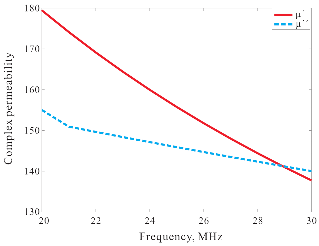
2.1. A Design of the Artificial Magnetic Conductor (AMC) with the Ferrite Material

Figure 1 presents the complex permeability of the MP2106-0M0 ferrite (Laird, [25]) applied to the design of the unit cell of the proposed artificial magnetic conductor (AMC). The complex permeability is made up of the real part ( μ ) and the imaginary part ( μ ). The permittivity value is set to 12. As shown in Figure 1, the MP2106-0M0 ferrite has high permeability on the HF band.
The unit cell geometry of the proposed AMC is illustrated in Figure 2a. The unit cell is composed of two substrates and the MP2106-0M0 ferrite with a side length of W A M C = 125 mm. The two substrates are the FR-4 types with a dielectric constant of 4.3, a thickness of h S = 1.6 mm, and a loss tangent of 0.0025. The thickness of the ferrite is h f = 7.5 mm. One FR-4 substrate is located on top of the ferrite and the other is on the bottom side. On the upper surface of the top FR-4 substrate, a square AMC patch with a side length of P A M C = 124 mm is positioned. The ground plane is located on the lower side of the bottom FR-4 substrate. Figure 2b depicts the boundary condition of the unit cell structure during the simulation. To simulate the reflection phase of the patch on the unit cell, a periodic boundary condition was established by setting two PEC (perfect electric conductor) walls and two PMC (perfect magnetic conductor) walls facing each other, and a full-wave simulation was conducted.
Figure 3 shows the simulated reflection phase of the unit cell of the AMC. The operating frequency of the unit cell structure is ordinarily defined as the frequency range in which the reflection phase varies from −90 to +90 [26]. The simulated operating frequency ratio bandwidth is 1.89:1 (19–36 MHz). In the simulation results, it was found that due to the high permeability value of the ferrite, which causes the high inductance value of the unit cell, the unit cell of the AMC can operate on the HF band while retaining a compact size of 0.007 × 0.007 × 0.0006 λ L 3 ( λ L is the wavelength of the lowest operating frequency in free space).

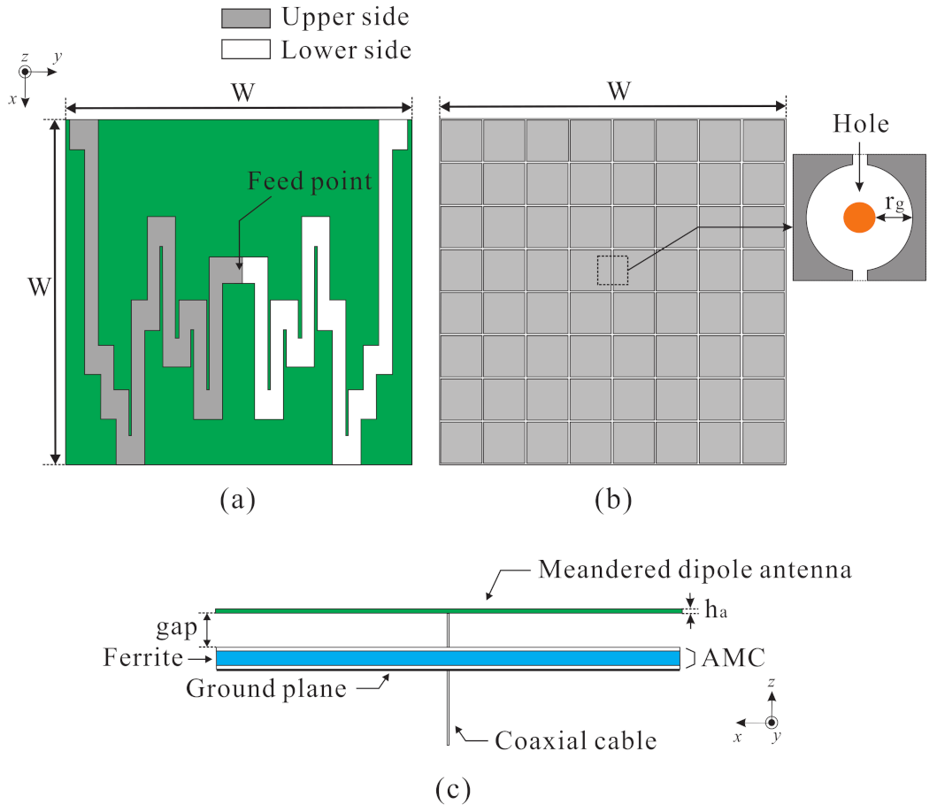
2.2. The Designed Antenna with the AMC

The design concept of a meandered dipole antenna is depicted in Figure 4. This design method was introduced by Bayraktar et al. [27]. The optimization procedure begins by dividing each dipole arm into ten segments. Each segment is assigned such that it is on a column of the grid, denoted in green, with two adjacent segments connected by a vertical line, denoted in red. A binary genetic algorithm (GA) is applied to derive the optimized position of the horizontal segment which is encoded as three bits. Therefore, the meandered dipole antenna is designed by using 30 bits in total. The binary GA is conducted with MATLAB programming linked to HFSS through an HFSS scripting interface. The optimization process in conducted with one hundred iterations, a population of 20, and a mutation rate of 0.1 with the single-point crossover scheme. The horizontal segment and vertical segment are modeled by a rectangular patches 82 × 85 mm 2 and 37 × 215 mm 2 in size, respectively. The optimization process is conducted with the presence of the AMC.
The optimized meandered dipole antenna is illustrated in Figure 5a. The Taconic RF-35 substrate, indicated with green in Figure 5a, with a dielectric constant of 3.5, a thickness of ( h a ) of 1.52 mm, and a loss tangent of 0.0018 is used to design the antenna. The side length of the substrate of the meandered dipole antenna is set to W = 1000 mm, which is the length of the reference monopole antenna used here (OMNI-A0245, ALARISANTENNA [28]). Each meandered dipole element is symmetrically located on the top and bottom side of the substrate, as indicated in grey and white, respectively. The designed meandered dipole antenna is fed by a coaxial cable at the feeding point shown in Figure 5a. Figure 5b shows the configuration of the designed AMC, which consists of 8 × 8 unit cells. The number of unit cells is set to constitute a surface with a side length of 1000 mm equal to the length of the reference monopole antenna. There is a hole through which a coaxial cable for excitation can pass through, as indicated by the orange circle in Figure 5b. A gap as large as r g = 1.9 mm was added to prevent short circuits of the AMC patch and coaxial cable. The proposed antenna with the AMC is depicted in Figure 5c. The AMC is located beneath of the antenna with a distance of a gap of 18 mm.

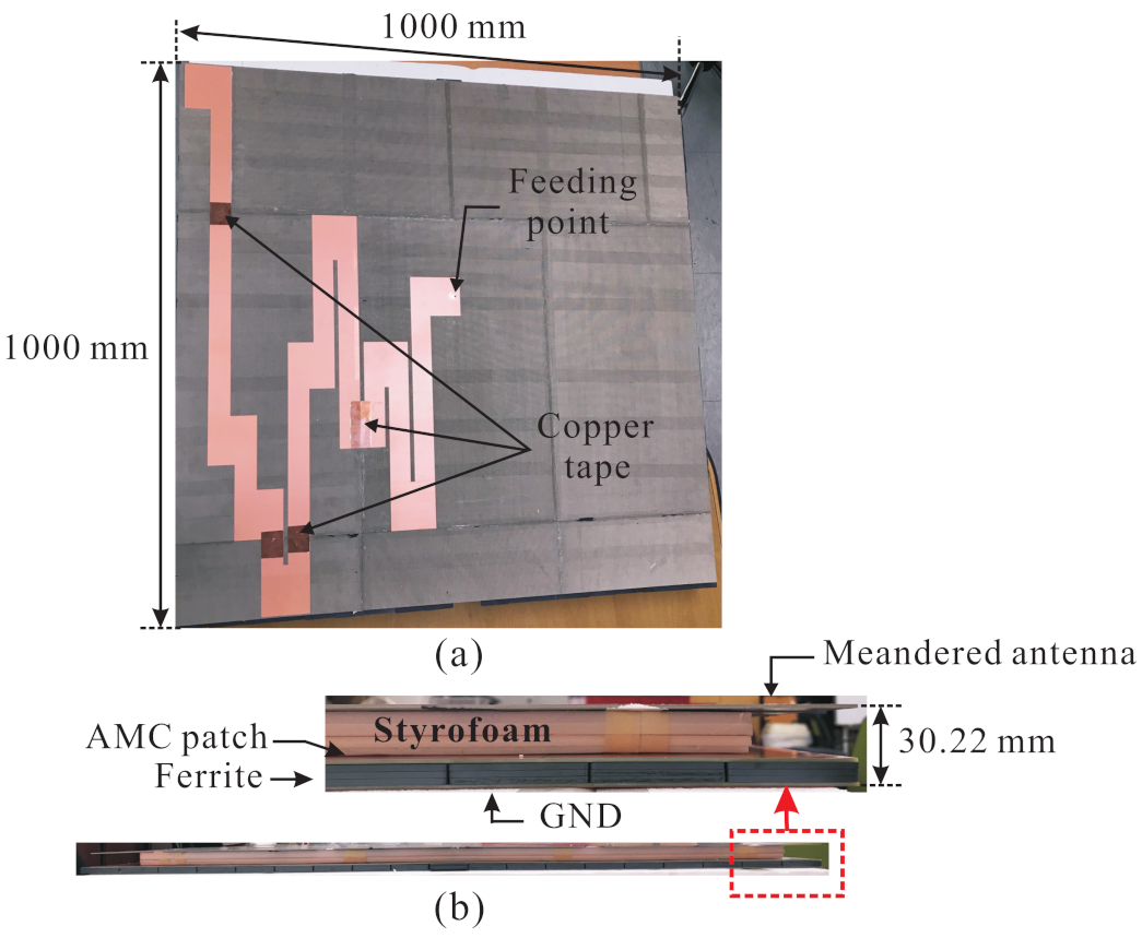
3. Experimental Verification

3.1. Performance of the Designed Antenna with the AMC

A prototype of the designed antenna with the AMC is fabricated and measured to verify the performance. Figure 6 presents a photograph of the fabricated meandered dipole antenna with the AMC. The antenna and AMC were etched separately and then electrically and physically connected to each other using copper tape and instant glue, respectively. Styrofoam is utilized to create an air gap between the substrate of the meandered dipole antenna and the AMC. The overall size of the fabricated antenna is 1000 × 1000 × 30.22 mm 3 .
Figure 7 presents the simulated and measured VSWRs of the proposed antenna with the AMC. An Agilent 8510C network analyzer was utilized to measure the VSWR. The proposed antenna meets VSWR characteristics (<3) on the HF band of 20–30 MHz. The discrepancy can be attributed to inaccuracies during the fabrication process, experimental tolerances, and to the assembly process.
To verify the effects of the AMC, the VSWR characteristics of the antenna with and without the AMC were simulated. The comparison of the VSWRs of the antenna according to the presence of the AMC is shown in Figure 8. When the AMC is applied, the antenna meets the VSWR characteristics (<3) in the 20–30 MHz band. On the other hand, the antenna does not satisfy the VSWR characteristics in the 20–30 MHz band. Therefore, it can be confirmed that impedance matching of the antenna is improved by applying the AMC.
Simulated radiation patterns of the proposed antenna with the AMC at 20 MHz, 25 MHz, and 30 MHz are illustrated in Figure 9. Due to the AMC effects, the main beam direction is formed on the + z -axis. Furthermore, it can be seen that the distance between the antenna and the AMC is closer than λ L /4 ( λ L is the wavelength of the lowest operating frequency in free space), which is the required distance between the antenna and a general reflector at which the performance of the antenna does not deteriorate. Despite the AMC works as reflector, the size of the AMC is significantly small related to the wavelength of the operating frequency of the antenna. Therefore, the back radiation is inevitably occurred.
The realized gain of the proposed antenna with the AMC at the + z -axis is shown in Figure 10. The realized gain varies from 22.2 dBi to 16 dBi within the operating frequency bandwidth. Consequently, it can be confirmed that the gain characteristics of the proposed antenna with the AMC are higher within the 20–30 MHz band compared to those of the reference commercial antenna [28], for which the corresponding values are approximately 24 dBi and 17.5 dBi at 20 MHz and 30 MHz. As a result, the proposed antenna with the AMC is shown to have reasonable gain characteristics.

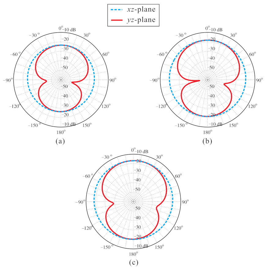
3.2. Experimental Results of the Designed Antenna with the AMC

In order to verify the performance of the designed antenna, the receiving power capabilities of the proposed antenna with the AMC and the reference monopole antenna [28] are measured and compared. Figure 11 shows the receiving power measurement setup. The distance between the receiving antennas (the proposed antenna with the AMC and the reference monopole antenna) and the transmitting antenna (MP1DXTR80, SUPER ANTENNA [29]) used in this experiment is 130 m. The receiving antennas are located on the rooftop of a ground vehicle. The receiving power of the reference monopole antenna was measured with a 1000 × 1000 mm 2 ground plane. The ground plane was implemented using copper tape on top of Styrofoam. The proposed antenna with the AMC was also on Styrofoam to protect it and the ground vehicle. The transmitting power was generated by a signal generator (E4438C, Keysight) and the receiving power was analyzed by a signal analyzer (FSV signal and spectrum analyzer, Rohde & Schwarz).
Figure 12 shows the measured receiving power results of the proposed antenna with the AMC and the reference monopole antenna. The transmitted power was set to 17 dBm and the power was transmitted from 20 MHz to 30 MHz at 2 MHz intervals. From these results, it can be confirmed that the received power of the proposed antenna with the AMC is higher than that of the reference monopole antenna on the HF band of 20–30 MHz.

4. Conclusions

A low-profile HF meandered dipole antenna with a ferrite-loaded AMC was proposed in this paper. By implementing ferrite given its high permeability on the HF band to the unit cell of the AMC, the unit cell structure can operate on the HF band while maintaining a compact size. The meandered dipole antenna was designed through optimization of a binary GA and combined with the 8 × 8 AMC. The VSWR bandwidth (<3) of the proposed antenna with the AMC covers the range of 20–30 MHz, which is within the HF band. In addition, due to the influence of the AMC, the proposed antenna has directional radiation patterns and maintains its performance capabilities despite the distance between the antenna and the AMC being closer than that of the antenna and a general reflector. As a result, the proposed antenna with the AMC is compact in the size of 0.06 × 0.06 × 0.002 λ L 3 ( λ L is the wavelength of the lowest operating frequency in free space). The performance of the proposed antenna with the AMC is confirmed by measurements. From these results, it can be indicated that the designed antenna can be used in applications operating on the HF band that require a low profile and a compact antenna, such as ground vehicle.

Author Contributions

Conceptualization, O.H.K. and K.C.H.; methodology, O.H.K.; software, O.H.K.; validation, O.H.K., W.B.P., H.J.L. and J.Y.; formal analysis, O.H.K.; investigation, O.H.K., H.J.L.; resources, O.H.K., W.B.P.; data curation, O.H.K., J.Y.; writing—original draft preparation, O.H.K.; writing—review and editing, O.H.K., W.B.P., H.J.L., J.Y. and K.C.H.; visualization, O.H.K; supervision, K.C.H.; project administration, K.C.H.; funding acquisition, K.C.H. All authors have read and agreed to the published version of the manuscript.

Funding

This work has been supported by the Future Combat System Network Technology Research Center program of Defense Acquisition Program Administration and Agency for Defense Development (UD190033ED).

Institutional Review Board Statement

Not applicable.

Informed Consent Statement

Not applicable.

Data Availability Statement

Data sharing not applicable.

Conflicts of Interest

The authors declare no conflict of interest.

References

  1. Austin, B.A.; Murray, K.P. Predicted and measured patterns of vehicle-mounted whip and loop antennas for near vertical incidence skywave (NVIS) propagation. In Proceedings of the IEE Colloquium on HF Antennas and Propagation, London, UK, 14 November 1995. [Google Scholar]
  2. Austin, B.A.; Murray, K.P. The Application of Characteristic-Mode Techniques to Vehicle-Mounted NVIS Antennas. IEEE Antennas Propag. Mag. 1998, 40, 7–21. [Google Scholar] [CrossRef]
  3. Austin, B.A.; Liu, W.C. Assessment of vehicle-mounted antennas for NVIS applications. IEE Proc. Microw. Antennas Propag. 2002, 149, 147–152. [Google Scholar] [CrossRef]
  4. Webster, R. 20-70 MC monopole antennas on ground-based vehicles. IRE Trans. Antennas Propag. 1957, 5, 363–368. [Google Scholar] [CrossRef]
  5. Smith, R.C.; Ignatenko, M.; Filipovic, D.S. Design of small loop antennas for on-the-move HF manpack radios. In Proceedings of the 2016 IEEE International Symposium on Antennas and Propagation (APSURSI), Fajardo, PuertoRico, 26 June–1 July 2016. [Google Scholar]
  6. Ignatenko, M.; Filipovic, S.D. On the Design of Vehicular Electrically Small Antennas for NVIS Communications. IEEE Trans. Antennas Propag. 2016, 64, 2136–2145. [Google Scholar] [CrossRef]
  7. Shrestha, S.; Ignatenko, M.; Filipovic, S.D. Combined Dipole-Multiturn Loop for Vehicle-Based High-Frequency (HF) Communications. In Proceedings of the 2014 IEEE Antennas and Propagation Society International Symposium (APSURSI), Memphis, MI, USA, 6–11 July 2014. [Google Scholar]
  8. Baker, J.; Youn, H.-S.; Celik, N.; Iskander, F.M. Low-Profile Multifrequency HF Antenna Design for Coastal Radar Applications. IEEE Antennas Wireless Propag. Lett. 2010, 9, 1119–1122. [Google Scholar] [CrossRef]
  9. Lopez, D.G.; Ignatenko, M.; Filipovic, S.D. Low-Profile Tri-band Inverted-F Antenna for Vehicular Applications in HF and VHF Bands. IEEE Trans. Antennas Propag. 2015, 63, 4632–4639. [Google Scholar] [CrossRef]
  10. Naji, D.K. Miniature Slotted Semi-Circular Dual-Band Antenna for WiMAX and WLAN Applications. J. Electromagn. Eng. Sci. 2020, 20, 115–124. [Google Scholar] [CrossRef]
  11. Ali, A.; Wang, H.; Yun, Y.; Lee, J.; Park, I. Compact Slot Antenna Integrated with a Photovoltaic Cell. J. Electromagn. Eng. Sci. 2020, 20, 248–253. [Google Scholar] [CrossRef]
  12. Jeong, M.-J.; Lim, J.-H.; Park, J.-W.; Park, S.-W.; Kim, N. Compact Slot Antenna Integrated with a Photovoltaic Cell. J. Electromagn. Eng. Sci. 2019, 19, 89–95. [Google Scholar] [CrossRef]
  13. Feresidis, A.P.; Goussetis, G.; Wang, S.; Vardaxoglou, J.C. Artificial magnetic conductor surfaces and their application to low-profile high-gain planar antennas. IEEE Trans. Antennas Propag. 2005, 53, 209–215. [Google Scholar] [CrossRef] [Green Version]
  14. Rajanna, P.K.T.; Rudramuni, K.; Kandasamy, K. A Wideband Circularly Polarized Slot Antenna Backed by a Frequency Selective Surface. J. Electromagn. Eng. Sci. 2019, 19, 166–171. [Google Scholar] [CrossRef]
  15. Foroozesh, A.; Shafai, L. Investigation Into the Application of Artificial Magnetic Conductors to Bandwidth Broadening, Gain Enhancement and Beam Shaping of Low Profile and Conventional Monopole Antenna. IEEE Trans. Antennas Propag. 2011, 59, 4–20. [Google Scholar] [CrossRef]
  16. Yang, F.; Rahmat-samii, Y. Reflection phase characteristics of the EBG ground plane for low profile wire antennas. IEEE Trans. Antennas Propag. 2003, 51, 2691–2703. [Google Scholar] [CrossRef] [Green Version]
  17. Bell, J.M.; Iskander, M.F. Equivalent Circuit Model of an Ultrawideband Hybrid EBG/Ferrite Structure. IEEE Antennas Wirel. Propag. Lett. 2008, 7, 573–576. [Google Scholar] [CrossRef]
  18. Gregoire, D.J.; White, C.R.; Colburn, J.S. Wideband Artificial Magnetic Conductors Loaded With Non-Foster Negative Inductors. In Proceedings of the 2012 IEEE International Workshop on Antenna Technology (iWAT), Tucson, AZ, USA, 5–7 March 2012. [Google Scholar]
  19. Sievenpiper, D.; Zhang, L.; Broas, R.F.J.; Alexopolous, N.G.; Yablonovitch, E. High-impedance electromagnetic surfaces with a forbidden frequency band. IEEE Trans. Microw. Theory Tech. 1999, 47, 2059–2074. [Google Scholar] [CrossRef] [Green Version]
  20. Diaz, R. Magnetic loading of artificial magnetic conductors for bandwidth enhancement. In Proceedings of the IEEE Antennas and Propagation Society International Symposium. Digest. Held in conjunction with: USNC/CNC/URSI North American Radio Sci. Meeting (Cat. No.03CH37450), Columbus, OH, USA, 22–27 June 2003. [Google Scholar]
  21. Bell, J.M.; Iskander, M.F.; Lee, J.J. Ultrawideband Hybrid EBG/Ferrite Ground Plane for Low-Profile Array Antennas. IEEE Trans. Antennas Propag. 2007, 55, 4–12. [Google Scholar] [CrossRef]
  22. Kwon, O.H.; Hwang, K.C. Low-Profile Spidron Fractal Dipole Antenna with a Ferrite-Loaded Artificial Magnetic Conductor for Manpack Applications. Appl. Sci. 2020, 10, 8843. [Google Scholar] [CrossRef]
  23. Warnagiris, T.J.; Minardo, T.J. Performance of a Meandered Line as an Electrically Small Transmitting Antenna. IEEE Trans. Antennas Propag. 1998, 46, 1797–1801. [Google Scholar] [CrossRef] [Green Version]
  24. Marrocco, G. Gain-Optimized Self-Resonant Meander Line Antennas for RFID Applications. IEEE Antennas Wirel. Propag. Lett. 2003, 2, 302–305. [Google Scholar] [CrossRef]
  25. MP2106-0M0. Available online: https://www.mouser.com/datasheet/2/987/MP2106-0M0-1650723.pdf (accessed on 22 January 2021).
  26. Trinh-Van, S.; Kwon, O.H.; Jung, E.; Park, J.; Yu, B.; Kim, K.; Seo, J.; Hwang, K.C. A low-profile high-gain and wideband log-periodic meandered dipole array antenna with a cascaded multi-section artificial magnetic conductor structure. Sensors 2019, 19, 4404–4415. [Google Scholar] [CrossRef] [Green Version]
  27. Bayraktar, Z.; Werner, P.L.; Werner, D.H. The design of miniature three-element stochastic Yagi-Uda arrays using particle swarm optimization. IEEE Antennas Wless Propag. Lett. 2006, 5, 22–26. [Google Scholar] [CrossRef]
  28. OMNI-A0245. Available online: http://www.alarisantennas.com/wp-content/uploads/2017/06/brochures /OMNI-A0245%20Version%201.2.pdf (accessed on 22 January 2021).
  29. MP1DXTR80. Available online: http://newsuperantenna.com/ (accessed on 22 January 2021).
Figure 1. Complex permeability of the MP2106-0M0 ferrite.
Applsci 11 02237 g001
Figure 2. Geometry of the proposed unit cell of the artificial magnetic conductor (AMC): (a) perspective-view; (b) boundary condition.
Applsci 11 02237 g002
Figure 3. Simulated reflection phase of the proposed unit cell of the artificial magnetic conductor (AMC).
Applsci 11 02237 g003
Figure 4. Design concept of a meandered dipole antenna.
Applsci 11 02237 g004
Figure 5. Geometry of the proposed antenna with the AMC: (a) meandered dipole antenna; (b) 8 × 8 AMC; (c) side-view.
Applsci 11 02237 g005
Figure 6. Photograph of the fabricated antenna with the AMC: (a) top-view; (b) side-view.
Applsci 11 02237 g006
Figure 7. Simulated and measured VSWRs of the proposed antenna with the AMC.
Applsci 11 02237 g007
Figure 8. Simulated VSWRs of the proposed antenna with and without of the AMC.
Applsci 11 02237 g008
Figure 9. Simulated radiation patterns of the meandered dipole antenna with the AMC: (a) 20 MHz; (b) 25 MHz; (c) 30 MHz.
Applsci 11 02237 g009
Figure 10. Simulated realized gain on the + z -axis of the meandered dipole antenna with the AMC.
Applsci 11 02237 g010
Figure 11. Receiving power measurement setup.
Applsci 11 02237 g011
Figure 12. Measured receiving power levels of the proposed antenna with the AMC and the reference monopole antenna.
Applsci 11 02237 g012
Publisher’s Note: MDPI stays neutral with regard to jurisdictional claims in published maps and institutional affiliations.

