Article

The Incorporation of Steel Slag into Belite-Sulfoaluminate Cement Clinkers

1
Slovenian National Building and Civil Engineering Institute, Dimičeva ulica 12, 1000 Ljubljana, Slovenia
2
SIJ Acroni d. o. o. Cesta Borisa Kidriča 44, 4270 Jesenice, Slovenia
*
Authors to whom correspondence should be addressed.
Appl. Sci. 2021, 11(4), 1840; https://doi.org/10.3390/app11041840
Submission received: 29 January 2021 / Revised: 15 February 2021 / Accepted: 17 February 2021 / Published: 19 February 2021

Abstract

:
The potential use of steel slag from treated steel slag in belite-sulfoaluminate cements was investigated in this study. Cement clinkers with two phase compositions were synthesized, allowing the incorporation of different amounts of steel slag. The phase composition and microstructure of cement clinkers at three different sintering temperatures were studied by X-ray powder diffraction and the Rietveld method, as well as scanning electron microscopy with energy dispersive spectrometry. The results showed that the targeted phase composition of clinkers was achieved at a sintering temperature of 1250 °C. However, a higher amount of perovskite instead of ferrite was detected in the clinker with a higher content of Ti-bearing bauxite. Apart from the main phases, such as belite, calcium sulfoaluminate, and ferrite, several minor phases were identified, including mayenite, perovskite, periclase, and alkali sulfates. In both clinker mixtures, a higher content of MgO in the steel slags resulted in the formation of periclase. Furthermore, the hydration kinetics and compressive strength at 7 and 28 days were studied in two cements prepared from clinkers sintered at 1250 °C. As evidenced by the results of isothermal calorimetry, the hydration kinetics were also influenced by the minor clinker phases. Cement with a higher content of calcium sulfoaluminate phase developed a higher compressive strength.

1. Introduction

The co-generated ferrous slag stream is an integral part of the steel production process. Slag is the biggest by-product stream of the steel sector, accounting for 90% with regards to the mass of by-product and waste generated [1]. In total, 30% of the world’s steel is produced using an Electric Arc Furnace (EAF), with scrap steel as the input and electricity as the energy source. On average, around 200 kg of co-products are generated from one ton of steel produced in this way [2]. In Europe, 15.7 million tons of steelmaking slag were produced in 2018, with 34.8% coming from EAF-based production and 12.5% from other processes, probably secondary metallurgical processes [3]. The most common use of EAF slag is as aggregate in road construction, for which EAF slag from carbon steel production is predominately used (EAF C slag). EAF C slag has excellent mechanical properties, which justify its use as an aggregate in the manufacturing of bituminous mixes [4]. Other uses for steel slags (EAF C slag, EAF stainless steel slag (EAF S slag), and ladle slag coming from secondary metallurgical processes) are as aggregate for concrete, waste water treatment, embankments and fill, and ground stabilization [5]. Their use in cement and other hydraulic binders has also been reported [6,7,8,9]. Although steel slag is highly recyclable, there is still room for improvement, and efforts in the steel industry are being made to move closer to the “zero-waste” goal. In order to achieve the “zero waste goal”, it is important to look for alternative applications for the use of steelmaking slags that are not yet in widespread use. In the cement industry, the possibility of producing low-carbon and low-energy cements using secondary mineral raw materials rich in aluminium is a promising solution, which would save natural resources and reduce the environmental impact of the production processes.
To date, only a few studies have demonstrated the use of steel slags in the production of belite-sulfoaluminate (BCSA) clinker [10,11]. BCSA clinkers are one of the most promising low carbon and low energy potential alternatives to ordinary Portland cement (OPC) clinkers, as they use a sintering temperature that is around 200 °C lower and less energy is consumed for the grinding process [12,13,14]. They consist of three main phases: Belite (C2S); calcium sulfoaluminate (C4A3Ś); and ferrite (C4AF). By definition, the most abundant phase is belite, which represents more than 50 wt.% of BCSA clinker [14]. Among the minor phases, periclase (M), gehlenite (C2AS), mayenite (C12A7), perovskite (CT), arcanite (KŚ), acermanite, magnetite, and anhydrite (CŚ) are the most commonly reported [15,16]. Although the targeted amounts of the main clinker phases can be well-predicted, the formation of minor phases strongly depends on the minor elements which are present in the raw materials [17,18]. Moreover, foreign elements can be incorporated into the main clinker phases, influencing the dynamics of crystal formation [19,20,21] and consequently affecting the hydraulic properties of the cement [22,23,24].
The aim of this study is to demonstrate and discuss the use of steel slag in BCSA cement clinker. BCSA clinkers of two targeted phase compositions were sintered at 1200, 1250, and 1300 °C, in order to describe the general microstructure, phase composition, and incorporation of minor elements into the hydraulic clinker phases. To reveal any potentially unfavorable influence of the material-derived impurities on the hydraulic properties, BCSA cements were prepared from clinkers sintered at 1250 °C. Early age hydraulic properties were investigated by isothermal calorimetry and compressive strength development was measured at 7 and 28 days of hydration.

2. Materials and Methods

2.1. Materials

The main raw materials used in this study were limestone and flysch (deep water siliciclastic rocks), steel slag, calcined bauxite, and white titanogypsum. For the correction, smaller quantities of mill scale, quartz, and calcite were also used. Steel slag, or more precisely slag mineral residue, was obtained from the processing of the mixture of EAF S slag and ladle slag. Slag processing involved weathering in the slag cooling yard, grinding, and metal recovery. The final product of the slag processing was steel granulate, which was returned to the EAF as steel scrap and slag mineral residue, the latter of which was used in this study. The treatments and processes which gave the mixture of EAF S slag and ladle slag its final properties are normal industrial practices. These processes and treatments are reported as Best Available Techniques by BREF documents.
With the exception of white titanogypsum, which was dried at 40 °C to prevent its transformation to anhydrite, all raw materials were dried to a constant mass at 105 °C. In order to prepare large batches of homogeneous raw materials, 5 kg of each material was milled in a ball mill, until it met the criteria that 95 wt.% of the material could pass through a 200 µm sieve. The exception was gypsum, which was not milled. The main oxide composition and loss on ignition at 950 °C in the raw materials for the clinker are given in Table 1.
The proportions of raw materials in the raw clinker mixtures were calculated using the Bogue method for sulfoaluminate cements [25]. The formulation of targeted phase compositions was based on the minimum and maximum amount of C4A3Ś in belite-rich sulfoaluminate clinkers [26]. A medium amount of C4AF was pointed (constant for both mixtures) and the C2S content was adjusted to reach the sum 95 wt.% (minor phases were estimated to be 5 wt.%). The intended phase compositions are given in Table 2, and the corresponding proportions of raw materials in the raw mixtures KMO1 and KMO2 are presented in Table 3.
Raw mixtures were homogenized in a laboratory ball mill (CAPCO Test Equipment Ball Mill Model 9VS). In total, 200 g of each mixture was homogenized in 200 mL of isopropanol, together with steel balls, for 3 h. Isopropanol was removed by vacuum drying (1 medium permeable filter paper was used), followed by oven drying at 40 °C overnight. The raw material mixtures were then pressed into pellets 30 mm in diameter, using a force of 10.6 kN, with a weight of 15 g. The clinker mixtures were sintered at 1200, 1250, and 1300 °C in a Protherm furnace (PLF 160/9), at a heating rate of 10 °C/min. Samples were held at the final temperature for 60 min and allowed to cool naturally in the closed furnace.
Cements were prepared from clinkers sintered at 1250 °C, as this was the lowest temperature at which the targeted phase composition was reached. Cement clinkers and white titanogypsum were ground using a laboratory disc mill to pass through a 125 µm sieve. The proportion of gypsum added to the clinkers depended on the clinker phase composition intended. Gypsum was blended with the ground clinkers at a gypsum/calcium sulfoaluminate molar ratio of 1 [27]; 5.60 wt.% in the KMO1 sample and 9.90 wt.% in KMO2. The prepared cements were homogenized in a Turbula for 1.5 h and further milled to a similar Blaine specific surface area (SSA) of approximately 4900 ± 150 cm2/g in order to eliminate the influence of the particle size on the reactivity of cement (Table 4). However, despite the uniform Blaine SSA, the measurement of the particle size distribution (PSD) indicated that the fineness of the cement was greater in the KM02 sample compared to KMO1 (Table 4, Figure 1).

2.2. Methods

The phase composition of the cement clinkers was determined using a PANalytical Empyrean X-ray diffractometer (Malvern Panalytical, Malvern, UK) equipped with CuKα radiation and a PIXcel 1D detector. The samples were ground to a particle size of less than 63 µm. Samples were manually backloaded into a circular sample holder with a 10 mm diameter in order to mitigate the possible preferred orientation. The samples were measured at 45 kV at a current of 40 mA, in the range of 4 to 70 ° 2θ, at a step size of 0.026° 2θ with a scan step time of 197 s. Analysis of X-ray diffraction patterns was performed using X’Pert High Score Plus diffraction software v. 4.9 from PANalytical, using PAN ICSD v. 3.4 powder diffraction files. The Rietveld refinement method was conducted using crystal structures by Snellings et al. [28]. The structures for cubic and orthorhombic calcium sulfoaluminate were adopted from the work of Cuesta et al. [29,30].
SEM/EDS analysis was performed to study the morphology, size, and distribution of the phases, as well as to assess which minor elements were incorporated into the phases of the clinker. Uncoated polished cross sections of clinker pellets in vertical profiles were examined by a JEOL IT500 LV Scanning Electron Microscope (SEM) equipped with an Energy Dispersive X ray spectrometer (EDS) with a W filament, operated at an accelerating voltage of 15 kV in low vacuum mode at a working distance of 10 mm.
The hydraulic reactivity of cements prepared from clinkers sintered at 1250 °C was assessed by isothermal conduction calorimetry using a TAM Air calorimeter (TA Instruments). In total, 12 g of cement (ground to below 0.125 mm) with a water/cement ratio of 0.5 was mixed with an Ultra Turrax tube dispenser for 1 min. Then, 6 g of mixed paste was placed into glass vials and immediately put into the calorimeter. The heat evolution of cement was evaluated for 7 days at 20 °C.
To determine the compressive strength of cement prepared from clinkers sintered at 1250 °C, cement pastes with a water/cement ratio (w/c) of 0.5 were poured into prismatic molds with dimensions of 10 × 10 × 25 mm. At 24 h, the cement paste samples were demolded and cured in a humidity chamber at a temperature of 20 ± 1 °C and 95% relative humidity until they were tested under laboratory conditions. The compressive strength of cement pastes was determined at 7 and 28 days, using a ToniNORM test device (ToniTechnic by Zwick) at a load rate of 0.05 kN/s. The results are given as the average of four measurements for each cement mixture.

3. Results

3.1. Clinkers

3.1.1. X-ray Powder Diffraction

The phase composition of cement clinkers KMO1 and KMO2, sintered at different temperatures, was determined by Rietveld refinement (Table 5). In both types of clinker, the overall content of the main clinker phases was closest to the targeted values following sintering at 1250 °C (Table 5). The most abundant phase was C2S, which was mainly presented in beta form. During cooling, less than 1 wt.% of the beta C2S was transformed into gamma modification in both KMO1 and KMO2 (Table 5). The amount of belite did not significantly vary between clinkers sintered at 1200, 1250, and 1300 °C (Table 5). The second most abundant phase was C4A3Ś, which presented in orthorhombic and cubic form. The orthorhombic modification dominated in both clinkers at all sintering temperatures (Table 5). The highest amount of C4A3Ś developed at 1250 °C in both KMO1 and KMO2 clinkers (Table 5).
With regards to the C4AF phase, the targeted amount was reached at all three sintering temperatures in KMO1, while the amount of C4AF detected in KMO2 was much lower than the value predicted, only reaching around 2 wt.% (Table 5). The amount of ferrite remained constant between 1250 and 1300 °C, and then increased slightly between 1200 and 1250 °C (Table 5). However, perovskite was present in both clinkers, with less than 1 wt.% detected in KMO1, compared to more than 5 wt.% in KM02 (Table 5). Ferrite is the artificial equivalent of natural mineral brownmillerite, having a structure similar to perovskite, which allows the substitution of various cations [31]. However, Ti was mainly incorporated into the raw clinker mixtures as a result of the presence of bauxite (Table 1), meaning the higher amount of perovskite in KMO2 can be explained by the larger amount of bauxite used in the KMO2 mixture (Table 3).
Among the minor phases, mayenite and periclase were detected in both clinkers. The amount of mayenite was higher in the KMO2 sample due to an increased content of the calcium sulfoaluminate phase. In both KMO1 and KMO2, the highest amount of mayenite was detected in samples sintered at 1200 °C, when the C4A3Ś was forming, while the lowest amount of C4A3Ś occurred at 1250 °C, which corresponds to the optimal sintering temperature at which the targeted values were reached. The periclase (free magnesia (f-MgO)) content was similar for KMO1 and KMO2, with values remaining constant across all sintering temperatures (Table 5). The amount of periclase, determined by Rietveld refinement, was slightly enhanced in the two clinkers. For BCSA clinkers synthesized by including either bottom ash or fly ash, values are reported to be between 0.4 and 2.3 wt.% [16,32,33]. The main source of Mg was steel slag (Table 1); however, the overall amount of MgO introduced in both raw clinker mixtures was around 2 wt.%. The values are below the limit, if compared to the OPC clinker requirements, where the content of MgO should not exceed 5 wt.% [34] in order to avoid the formation of dead-burned MgO with a very slow hydration rate, as the late expansion of MgO would jeopardize the cement soundness [35]. At all sintering temperatures, some aphthitalite (K3Na(SO4)2), langbeinite (K2Ca2(SO4)3), and arcanite (K2SO4) were also detected in KMO1 (Table 5), as a consequence of the higher content of fly ash, which contains alkalis.

3.1.2. SEM/EDS

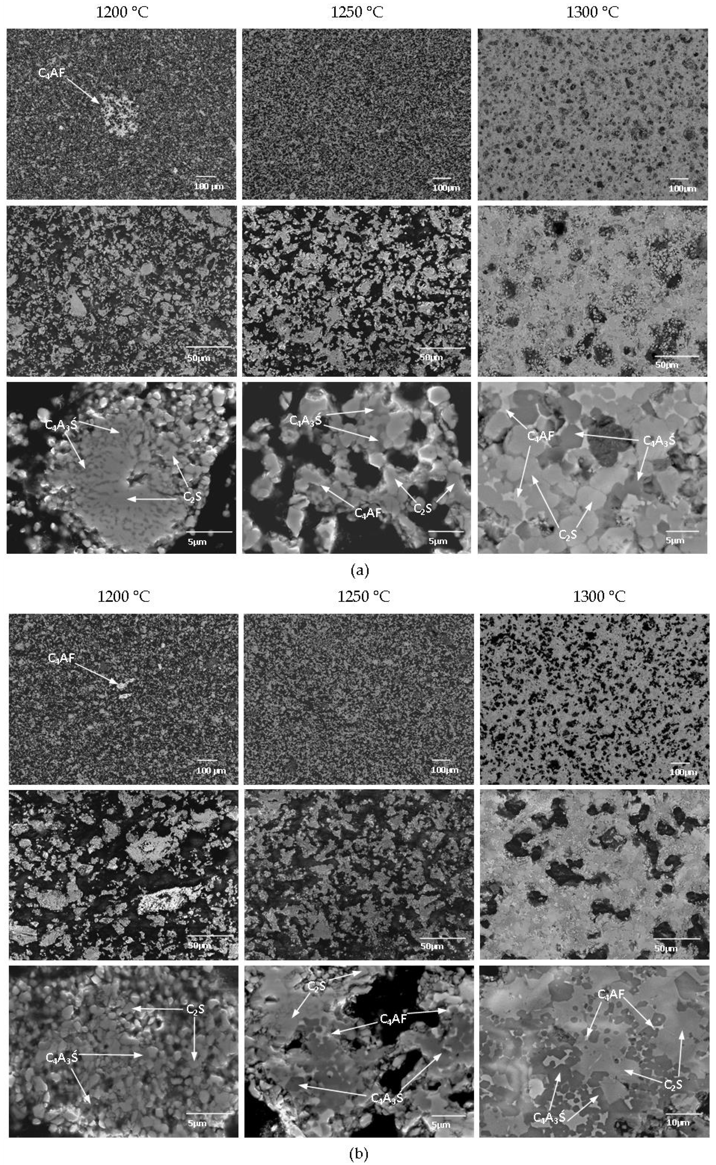
Clinkers showed a clear decrease in porosity as the sintering temperature increased (Figure 2). In both mixtures, a temperature of 1200 °C was sufficient for developing the main reactive phases. However, X-ray Powder Diffraction (XRD) analysis revealed that the targeted amounts were not achieved at 1200 °C. Subhedral to euhedral C2S and C4A3Ś grains were already clearly developed at 1200 °C in both KMO1 and KMO2 clinkers. However, at 1200 °C, the clinkers showed an inhomogeneous structure, as C4AF was not present in the interstitial areas, but formed in individual nests (Figure 2). In both mixtures, sintering at 1250 °C resulted in a homogeneous structure, formed by subhedral to euhedral C2S and C4A3Ś grains and C4AF in the interstitial area (Figure 2). Raising the sintering temperature to 1300 °C led to structure densification, and increased the number of euhedral C2S and C4A3Ś grains (Figure 2). 
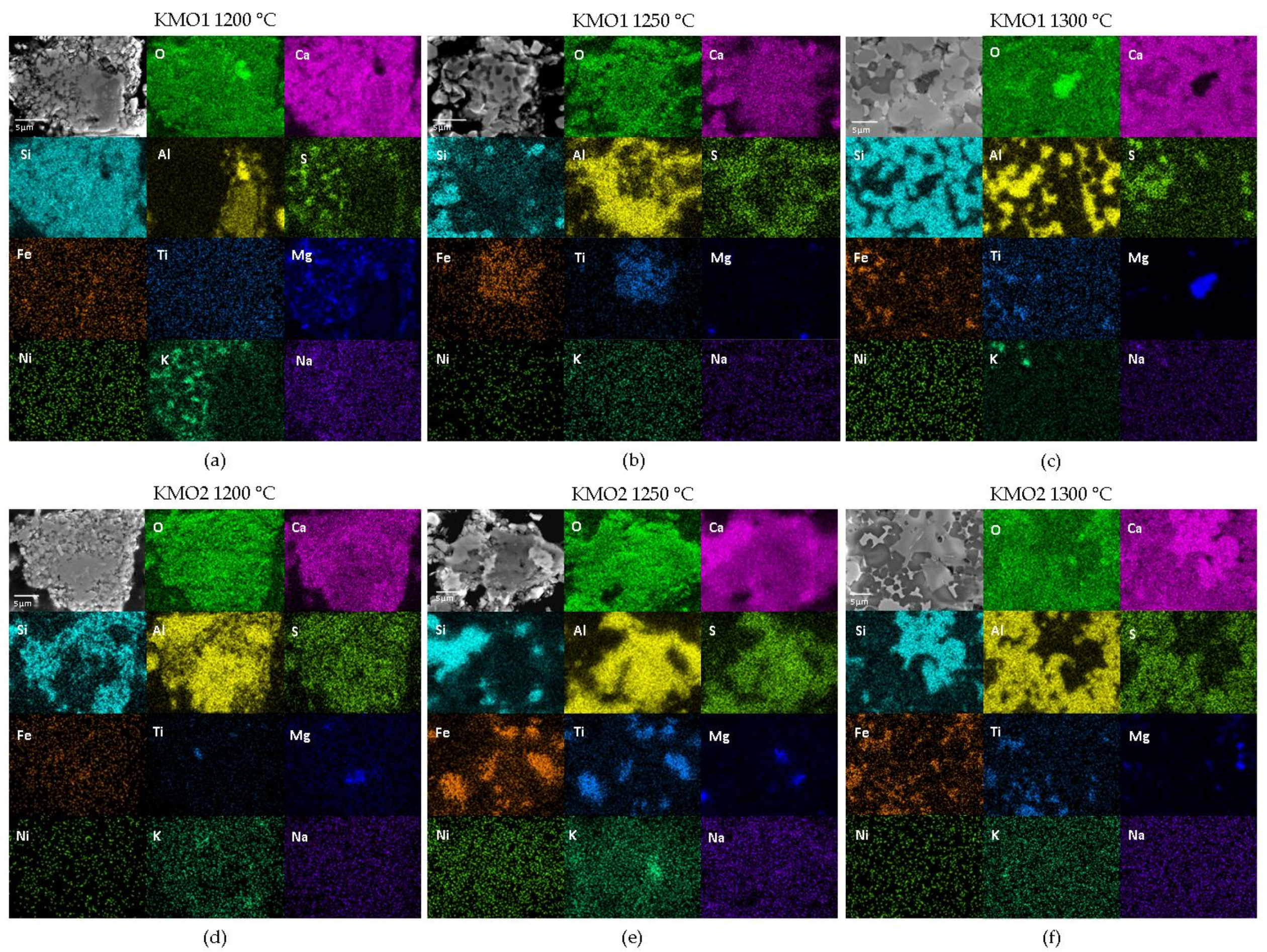
Figure 3 shows elemental EDS maps for the KMO1 and KMO2 clinkers sintered at 1200, 1250, and 1300 °C.
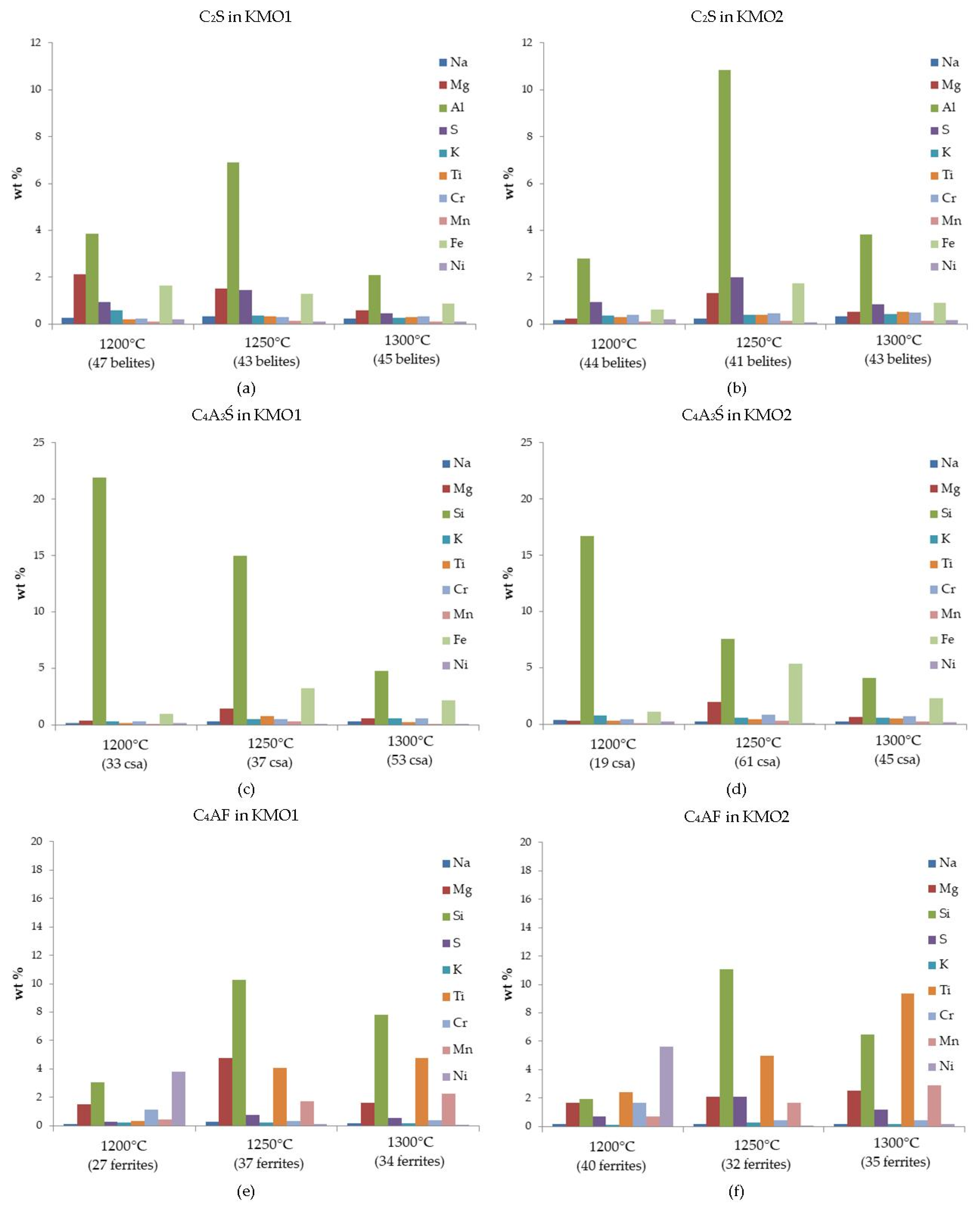
Furthermore, the amounts of minor individual elements measured (EDS point measurements and SEM statistics), incorporated in the main clinker phases, are presented as sequences, in order of the maximum to minimum quantity detected. Belite enables various element substitutions [12,23,36,37,38]. It exhibited Al, Mg, Fe, S, K, Cr, Ti, Na, Ni, and Mn in the KMO1 clinker and Al, S, Fe, Mg, Cr, Ti, K, Na, Ni, and Mn in the KMO2 clinker. The higher amount of S detected in KMO2 corresponds to a higher gypsum content (Table 3). On the other hand, the higher Mg content of the KMO1 belites, as detected by EDS analysis, cannot be explained by a higher input from the raw materials (Table 1 and Table 3). However, the highest amount of Mg in KMO1 belites was detected at 1200 °C, where the sintering was not complete, as evident from the EDS maps (Figure 4a). In both clinker mixtures, the highest amount of Al was incorporated into belite at 1250 °C (Figure 4a,b). On the other hand, the amount of Mg incorporated varied between the clinker mixtures. In KMO1, the amount of Mg in the belite phase clearly decreased with an increase in the sintering temperature (Figure 4a), while in KMO2 belites, the maximum amount of Mg was detected at 1250 °C (Figure 4b). In both clinkers, belites included the maximum amount of S at 1250 °C. The amount of Fe in the KMO1 belites decreased with a rise in the sintering temperature (Figure 4a), while in KMO2, the maximum amount of Fe incorporated in belite occurred at 1250 °C (Figure 4b). The maximum amount of K incorporated into belites occurred at 1200 °C in KMO1, while in KMO2, the K content of belites did not change as a result of the sintering temperature.
In both clinkers, calcium sulfoaluminate included minor elements in the same sequence, with Si, Fe, and Mg, followed by K, Cr, Ti, Na, Mn, and Ni. The quantity of Si decreased with rising temperatures in both KMO1 and KMO2, while the maximum amount of Fe and Mg occurred at 1250 °C (Figure 4c,d). The high Si content can be attributed to the fact that calcium sulfoaluminate is an end member of sodalite solid solution, in which Si is replaced by Al [39,40]. Consequently, increasing the sintering temperature resulted in decreased amounts of Si (Figure 4c,d).
In KMO1, ferrite included Si, Ti, Mg, Mn, Ni, Cr, S, K, and Na, which slightly differed to the sequence of Si, Ti, Mg, Ni, Mn, S, Cr, K, and Na incorporated in KMO2. In both KMO1 and KMO2, the maximum amount of Si was incorporated into the ferrite phase at 1250 °C (Figure 4e,f). However, it has already been reported that Si and S commonly replace Fe or Al in a ferrite structure [41]. In both clinkers, the amount of Ti incorporated into the ferrite phase increased when raising the sintering temperature (Figure 4e,f). In KMO1, the maximum amount of Mg was incorporated into ferrites at 1250 °C, while in KMO2, the amount of Mg was constant across all sintering temperatures. In both clinkers, the maximum amounts of Ni and Cr were incorporated into ferrite at 1200 °C (Figure 4e,f).
Amongst the minor clinker phases, EDS mapping identified Mg-rich areas of periclase, which were seen in both clinker mixtures across all three sintering temperatures (Figure 3). Although steel slag contains a large amount of MgO (Table 1), the overall amount of Mg in clinkers was not substantially increased as clinker raw mixtures only incorporated around 8 or 11 wt.% of steel slag (Table 3). Moreover, the amount of periclase, determined by Rietveld refinement, was not very considerable (Table 5). The Ti-enriched areas correspond to perovskite, which was also identified in all clinkers (Figure 3a–d), but it was present to a greater degree in the KMO2 mixture (Figure 3d–f), as also supported by the XRD results (Table 5). Ca- and Al-enriched interstitial areas were observed in all clinkers, which can be attributed to the mayenite phase (Figure 3). KMO1 clinker mixtures also showed some K- and S-enriched areas of K-sulphate minor phases (Figure 3a–c).

3.2. Cements

3.2.1. Isothermal Conduction Calorimetry

The hydration heat of the cements analysed is shown in Figure 5. The results showed that the kinetics of the two cements differ significantly.
Due to the external mixing method used, the first peak assigned to the heat of wetting and the early reaction during hydration [27,42,43] was not included. As can be seen from the results, the KMO1 cement reacted faster than the KMO2. Namely, the induction period for the KMO1 was very short following the first peak, lasting up to about 2 h of hydration in comparison to KMO2, where the induction period lasted until about 6 h of hydration before the main peak occurred. This period is attributed to the dissolution of clinker and the early formation of ettringite [27,43,44]. As follows, the main peak then occurred, which is attributed to the setting and hardening of the paste and the dissolution of calcium sulfoaluminate, together with gypsum, and the formation of ettringite and aluminium hydroxide [42,45,46]. This peak occurred after 4 h in KMO 1 and after 7 h in KMO2. Despite the fact that KMO2 contained a higher amount of highly reactive calcium sulfoaluminate phase, and that it had slightly finer particles compared to the KMO1, according to PSD measurement of the cement, which enhances its reactivity [47], the KMO1 reacted faster. However, this could be due to the presence of alkali sulfates (arcanite, aphthitalite, and Ca-langebeinite) in the KMO1. As already reported elsewhere, alkali sulfates have a significant effect on the hydration rate and setting time of cement. Namely, according to data in the literature [48,49,50], the reactivity of cement is accelerated in the presence of alkali sulfates. In addition, the KMO1 sample in comparison to KMO2 contains more ferrite, which is an active hydraulic phase, while it contains less perovskite, which is an inert phase [28,29,30]. Furthermore, the KMO2 sample displayed a second heat maximum after 11.5 h of hydration, which was attributed to the depletion of gypsum and the subsequent precipitation of monosulfate [42,43,51]. In KMO1, on the other hand, where a higher calcium sulfoaluminate amount was present, only a shoulder was observed at 6.5 h of hydration. This was probably due to the lower gypsum content in this mixture, which favored the formation of ettringite over monosulfate, and the peak was shifted to an earlier time [42,52].
The cumulative heat results are shown in Figure 6 and Table 6. After 7 days of hydration, the amount of cumulative heat released was smaller in the KMO1 cement (176.6 J/g) than in KMO2 (223.8 J/g), indicating that more heat was released during the hydration of KMO2. This was attributed to a higher amount of calcium sulfoaluminate and a higher degree of hydration in the KMO2 cement.

3.2.2. Compressive Strength

As can be seen from the results in Table 7, the compressive strengths of the cement pastes vary significantly between 7 and 28 days of hydration, the extent of which depends on the cement mixture (KMO1 or KMO2). The compressive strength was higher in the KMO2 cement than the KMO1 cement at both 7 and 28 days, which is mainly related to the increased calcium sulfoaluminate content (35 wt.% of C4A3Ś in KMO2 compared to 20 wt.% of C4A3Ś in KMO1).
Consequently, more gypsum was needed in the KMO2 cement mixture for obtaining an equal molar ratio. Ettringite and aluminum hydroxide are formed from calcium sulphoaluminate in the presence of water and a source of sulphate. The more calcium sulphoaluminate is added, the more ettringite forms, the higher the volume of hydrates, and the lower the amount of available water and available space for growing hydrates [26,51,53]. It is ettringite which gives the initial strength (reaction detected by isothermal calorimetry). Since more belite reacts during later age periods, this will further contribute to the long-term development of compressive strength [54]. The increase in the compressive strength of the cements from 7 to 28 days is smaller in KMO1 than in the KMO2 cement. Both studied cement clinkers contained slightly increased periclase (f-MgO) contents. The formation of Mg(OH)2 during f-MgO hydration leads to inner stresses, causing a reduction in the compressive strength [55]. Nevertheless, generally, as observed for OPC, there was a decrease in the compressive strength with increased f-MgO contents (> 3 wt.%), especially at later ages [55,56,57]. At the same time, there was a compressive strength reduction with an increased f-MgO content, relative to a reference paste without additional f-MgO (ordinary Portland cement mix), mainly attributed to the increase in porosity and lower hydration of f-MgO mixtures compared to MgO-free mixtures [58].

4. Conclusions

The present study presents the results of an investigation into the use of steel slag in belite-sulfoaluminate cement clinkers.
For the two clinker phase compositions targeted, it was possible to incorporate between 7.7 and 11.1 wt.% of the steel slag into the raw clinker meal. The results showed that it was possible to achieve the targeted phase composition of both types of clinker at a sintering temperature of 1250 °C. In addition to the main phases of belite, calcium sulfoaluminate, and ferrite, minor phases were also identified. While mayenite, perovskite, and periclase were identified in both clinkers at all temperatures, alkali sulfates were mainly identified in the KMO1 clinker, since it contained more fly ash with enhanced alkalis. Incorporation of the steel slag especially resulted in the formation of periclase in the two clinkers, since it contains elevated levels of MgO. Furthermore, a higher content of Ti-bearing bauxite in the KMO2 clinker raw mixture promoted the formation of perovskite. A higher amount of mayenite was observed at the lowest sintering temperature (1200 °C) in both clinker mixtures, but it was higher in KMO2 due to a higher amount of the calcium sulfoaluminate phase. As evidenced by SEM/EDS, a clear porosity decrease and clearer phase development were seen in the clinkers with increased sintering temperatures. Furthermore, various foreign ions were incorporated into the main phases.
The hydration kinetics of the cements prepared by clinkers were influenced by both the major and minor phases. The heat of hydration was higher in the KMO2, which was made from clinker with a higher content of very reactive calcium sulfoaluminate. Similarly, the compressive strength of cement was higher in the KMO2 cement at both 7 and 28 days. The latter also showed a greater increase in compressive strength development compared to KMO1, with a larger proportion of belite.
The results confirmed that steel slag can be incorporated into belite-sulfoaluminate cement clinkers. The cements showed appropriate hydraulic characteristics and developed a sufficient compressive strength.

Author Contributions

Conceptualization, L.Ž. and S.D.; methodology, S.D. and L.Ž.; analysis, L.Ž., K.Š., and M.B.; writing—original draft preparation, L.Ž., K.Š., M.B., M.L., and S.D.; writing—review and editing, L.Ž., M.B., K.Š., and S.D.; funding acquisition, S.D. All authors have read and agreed to the published version of the manuscript.

Funding

The study has received funding from the European Institute of Innovation and Technology (EIT), a body of the European Union, under Horizon 2020, the EU Framework Programme for Research and Innovation (RIS-ALiCE, project no. 18258).

Data Availability Statement

Data is contained within the article.

Acknowledgments

The Metrology Institute of the Republic of Slovenia is acknowledged for the use of XRF.

Conflicts of Interest

The authors declare no conflict of interest.

References

  1. Worldsteel Association. Steel Industry Co-Products. Worldsteel Position Paper, 2018. Available online: https://www.worldsteel.org/en/dam/jcr:1b916a6d-06fd-4e84-b35d-c1d911d18df4/Fact_By-products_2018.pdf (accessed on 20 January 2021).
  2. Worldsteel Association. Steel Industry by-Products; Worldsteel Association: Brussels, Belgium, 2010. [Google Scholar]
  3. Euroslag. Available online: www.eursolag.com (accessed on 20 January 2021).
  4. Skaf, M.; Manso, J.M.; Aragón, A.; Fuente-Alonso, J.A.; Ortega-López, V. EAF slag in asphalt mixes: A brief review of its possible re-use. Resour. Conserv. Recycl. 2017, 120, 176–185. [Google Scholar] [CrossRef]
  5. Euroslag and Eurofer. Position Paper on the Status of Ferrous Slag Complying with the Waste Framework Directive (Article 5/6) and the REACH Regultion. Euroslag and Eurofer Position Paper, 2012. Available online: http://projects.gibb.co.za/Portals/3/App%20J13_Position_Paper_April_2012.pdf (accessed on 20 January 2021).
  6. Yüksel, İ. A review of steel slag usage in construction industry for sustainable development. Environ. Dev. Sustain. 2017, 19, 369–384. [Google Scholar] [CrossRef]
  7. Shi, C.; Qian, J. High performance cementing materials from industrial slags—A review. Resour. Conserv. Recycl. 2000, 29, 195–207. [Google Scholar] [CrossRef]
  8. Najm, O.; El-Hassan, H.; El-Dieb, A. Ladle slag characteristics and use in mortar and concrete: A comprehensive review. J. Cleaner Prod. 2021, 288, 125584. [Google Scholar] [CrossRef]
  9. Jiang, Y.; Ling, T.-C.; Shi, C.; Pan, S.-Y. Characteristics of steel slags and their use in cement and concrete—A review. Resour. Conserv. Recycl. 2018, 136, 187–197. [Google Scholar] [CrossRef]
  10. Iacobescu, R.I.; Pontikes, Y.; Koumpouri, D.; Angelopolous, G.N. Synthesis, characterization and properties of calcium ferroaluminate belite cements produced with electric arc furnace steel slag as raw material. Cem. Concr. Compos. 2013, 44, 1–8. [Google Scholar] [CrossRef]
  11. Isteri, V.; Ohenoja, K.; Hanein, T.; Kinoshita, H.; Tanskanen, P.; Illikainen, M.; Fabritius, T. Production and properties of ferrite-rich CSAB cement from metallurgical industry residues. Sci. Total Environ. 2020, 712, 136208. [Google Scholar] [CrossRef]
  12. Strigáč, J.; Palou, M.; Krištín, J.; Majling, J. Morphology and Chemical composition of minerals inside the phase assemblage C-C2S-C4A3S-C4AF-CS relevant to sulphoaluminate belite cements. Ceram. Silik. 1999, 44, 26–34. [Google Scholar]
  13. Quillin, K. Performance of belite-sulfoaluminate cements. Cem. Conc. Res. 2001, 31, 1341–1349. [Google Scholar] [CrossRef]
  14. Gartner, E.; Sui, T. Alternative cement clinkers. Cem. Concr. Res. 2018, 114, 27–39. [Google Scholar] [CrossRef]
  15. Álvarez-Pinazo, G.; Cuesta, A.; García-Matéa, M.; Santacruz, I.; Losillaa, E.R.; Dela Torre, A.G.; León-Reina, L.; Aranda, M.A.G. Rietveld quantitative phase analysis of Yeelimite-containing cements. Cem. Concr. Res. 2012, 42, 960–971. [Google Scholar] [CrossRef] [Green Version]
  16. Bullerjahn, F.; Schmitt, D.; Ben Haha, M. Effect of raw mix design and clinkering process on the formation and mineralogical composition of (ternesite) belite calcium sulphoaluminate ferrite clinker. Cem. Concr. Res. 2014, 59, 87–95. [Google Scholar] [CrossRef]
  17. Mehta, P.K. Investigations on energy-saving cements. World Cem. Technol. 1980, 11, 166–177. [Google Scholar]
  18. Majling, J.; Sahu, S.; Vlna, M.; Roy, D.M. Relationship between raw mixture and mineralogical composition of sulfoaluminate belite clinkers in the system CaO-SiO2-Al2O3-Fe2O3-SO3. Cem. Concr. Res. 1993, 23, 1351–1356. [Google Scholar] [CrossRef]
  19. Kolovos, K.; Tsivilis, S.; Kakali, G. The effect of foreign ions on the reactivity of the CaO-SiO2-Al2O3-Fe2O3 system. Part I: Anions. Cem. Concr. Res. 2002, 31, 425–429. [Google Scholar] [CrossRef]
  20. Kolovos, K.; Tsivilis, S.; Kakali, G. The effect of foreign ions on the reactivity of the CaO-SiO2-Al2O3-Fe2O3 system. Part II: Cations. Cem. Concr. Res. 2002, 31, 463–469. [Google Scholar] [CrossRef]
  21. Kolovos, K.; Tsivilis, S.; Kakali, G. SEM examination of clinkers containing foreign elements. Cem. Concr. Com. 2005, 27, 163–170. [Google Scholar] [CrossRef]
  22. Arjunan, P.; Silsbee, M.R.; Roy, D.M. Sulfoaluminate-belite cement from low-calcium fly ash and sulfur-rich and other industrial by-products. Cem. Concr. Res. 1999, 29, 1305–1311. [Google Scholar] [CrossRef]
  23. Kim, Y.M.; Hong, S.H. Influence of Minor Ions on the Stability and Hydration rates of β-Dicalcium Silicate. J. Am. Chem. Soc. 2004, 87, 900–905. [Google Scholar] [CrossRef]
  24. Ma, B.; Li, X.; Mao, Y.; Shen, X. Synthesis and characterization of high belite sulfoaluminate cement through rich alumina fly ash and desulfurization gypsum. Ceram. Silik. 2013, 57, 7–13. [Google Scholar]
  25. Majling, J.; Strigáč, J.; RoY, D.M. Generalized Bogue computations to forecast the mineralogical composition of sulfoaluminate cements based on fly ashes. Adv. Cem. Res. 1999, 11, 27–34. [Google Scholar] [CrossRef]
  26. Gartner, E. CSA and Belite-Rich Clinkers and Cements; UNESCO: Paris, France, 2017. [Google Scholar]
  27. Winnefeld, F.; Barlag, S. Calorimetric and thermogravimetric study on the influence of calcium sulfate on the hydration of ye’elimite. J. Therm. Anal. Calorim. 2012, 101, 949–957. [Google Scholar] [CrossRef] [Green Version]
  28. Snellings, R. X-ray powder diffraction applied to cement. In A Practical Guide to Microstructural Analysis of Cementitious Materials, 1st ed.; Scrivener, K., Snellings, R., Lothenbach, B., Eds.; CRC Press: Boca Raton, FL, USA, 2018; pp. 126–195. [Google Scholar] [CrossRef]
  29. Cuesta, A.; De la Torre, A.G.; Losilla, E.R.; Peterson, V.K.; Rejmak, P.; Ayuela, A.; Frontera, C.; Aranda, M.A.G. Structure, Atomistic Simulations, and Phase Transition of Stoichiometric Yeelimite. Chem. Mater. 2013, 25, 1680–1687. [Google Scholar] [CrossRef] [Green Version]
  30. Cuesta, A.A.; De la Torre, Á.G.; Losilla, E.R.; Santacruz, I.; Aranda, M.A.G. Pseudocubic Crystal Structure and Phase Transition in Doped Ye’elimite. Cryst. Growth Des. 2014, 14, 5158–5163. [Google Scholar] [CrossRef] [Green Version]
  31. Aleksandrov, K.S.; Beznosikov, B.V. Hierarchy of perovskite-like crystals (review). Fiz. Tverd. Tela. 1997, 37, 785–808. [Google Scholar] [CrossRef]
  32. Dolenec, S.; Šter, K.; Borštnar, M.; Nagode, K.; Ipavec, A.; Žibret, L. Effect of the Cooling Regime on the Mineralogy and Reactivity of Belite-Sulfoaluminate Clinkers. Minerals 2020, 10, 910. [Google Scholar] [CrossRef]
  33. Bullerjahn, F.; Zajac, M.; Skocek, J.; Ben Haha, M. The role of boron during the early hydration of belite ye’elimite ferrite cements. Constr. Build. Mater. 2019, 215, 252–263. [Google Scholar] [CrossRef]
  34. CEN 197-1. Cement—Part 1: Composition, Specifications and Conformity Criteria for Common Cements; CEN: Brussels, Belgium, 2011. [Google Scholar]
  35. Mehta, P.K. History and status of performance tests for evaluation of soundness of cements, cement standards—evolution and trends. In ASTM STP 663. Philadephia: American Society for Testing and Materials; ASTM: West Conshohocken, PA, USA, 1978; pp. 35–60. [Google Scholar]
  36. Ghosh, S.N.; Rao, P.B.; Paul, A.K.; Raina, K. The chemistry of dicalcium silicate mineral. J. Mater. Sci. 1979, 14, 1554–1566. [Google Scholar] [CrossRef]
  37. Lai, G.C.; Nojiri, T.; Nakano, K. Studies of the stability of β-Ca2SiO4 dopped by minor ions. Cem. Concr. Res. 1992, 22, 743–754. [Google Scholar] [CrossRef]
  38. Morsli, K.; De la Tore, A.G.; Stöber, S.; Cuberos, A.J.M. Quantitative Phase Analysis of Laboratory-Active Belite Clinkers by Synchrotron Powder Diffraction. J. Am. Ceram. Soc. 2007, 90, 3205–3212. [Google Scholar] [CrossRef]
  39. Moteki, T.; Chaikittisilp, W.; Sakamoto, Y.; Shimojima, A.; Okubo, T. Role of Acidic Pretreatment of Layered Silicate RUB-15 in Its Topotactic Conversion into Pure Silica Sodalite. Chem. Mater. 2011, 23, 3564–3570. [Google Scholar] [CrossRef]
  40. Pedersen, M.T.; Jensen, F.; Skibsted, J. Structural Investigation of Ye’elimite, Ca4Al6O12SO4, by 27Al MAS and MQMAS NMR at Different Magnetic Fields. J. Phys. Chem. C 2018, 122, 12077–12089. [Google Scholar] [CrossRef]
  41. Yanwei, Z.; Nanru, Y. A comparative study of the ferritephase in high-iron cements with the pure C2AxF1−X by Mössbauer spectroscopy. Cem. Concr. Res. 1991, 21, 31–37. [Google Scholar] [CrossRef]
  42. Chen, I.A.; Juenger, M.C.G. Synthesis and hydration of calcium sulfoaluminate-belite cements with varied phase compositions. J. Mater. Sci. 2011, 46, 2568–2577. [Google Scholar] [CrossRef]
  43. Rungchet, A.; Poon, C.S.; Chindaprasirt, P.; Pimraksa, K. Synthesis of low-temperature calcium sulfoaluminate-belite cements from industrial wastes and their hydration: Comparative studies between lignite fly ash and bottom ash. Cem. Concr. Compos. 2017, 83, 10–19. [Google Scholar] [CrossRef]
  44. Shen, Y.; Li, X.; Chen, X.; Zhang, W.; Yang, D. Synthesis and calorimetric study of hydration behavior of sulfate-rich belite sulfoaluminate cements with different phase compositions. J. Therm. Anal. Calorim. 2018, 133, 1281–1289. [Google Scholar] [CrossRef]
  45. Winnefeld, F.; Lothenbach, B. Hydration of calcium sulfoaluminate cements—Experimental findings and thermodynamic modelling. Cem. Concr. Res. 2010, 40, 1239–1247. [Google Scholar] [CrossRef]
  46. Zhang, L.; Glasser, F.P. Hydration of calcium sulfoaluminate cement at less than 24 h. Adv. Cem. Res. 2002, 14, 15. [Google Scholar] [CrossRef]
  47. Morin, V.; Termkhajornkit, P.; Huet, B.; Pham, G. Impact of quantity of anhydrite, water to binder ratio, fineness on kinetics and phase assemblage of belite-ye’elimite-ferrite cement. Cem. Concr. Res. 2017, 99, 8–17. [Google Scholar] [CrossRef]
  48. Juenger, M.C.G.; Jennings, H.M. Effects of High Alkalinity on Cement Pastes. ACI Mater. J. 2001, 98. Available online: https://trid.trb.org/view/685934 (accessed on 24 January 2021).
  49. Lee, J.K.; Chu, Y.S.; Kwon, C.W. The Effects of Alkali Sulfate on the Hydration of a C3A−CaSO4⋅2H2O System. J. Korean Ceram. Soc. 2007, 44, 471–476. [Google Scholar] [CrossRef]
  50. Yang, K.; Zhong, M.; Magee, B.; Yang, C.; Wang, C.; Zhu, X.; Zhang, Z. Investigation of effects of Portland cement fineness and alkali content on concrete plastic shrinkage cracking. Constr. Build. Mater. 2017, 144, 279–290. [Google Scholar] [CrossRef] [Green Version]
  51. Winnefeld, F.; Martin, L.H.J.; Müller, C.J.; Lothenbach, B. Using gypsum to control hydration kinetics of CSA cements. Constr. Build. Mater. 2017, 155, 154–163. [Google Scholar] [CrossRef]
  52. Jeong, Y.; Hargis, C.W.; Chun, C.S.; Moon, J. The effect of water and gypsum content on strätlingite formation in calcium sulfoaluminate-belite cement pastes. Constr. Build. Mater. 2018, 166, 712–722. [Google Scholar] [CrossRef]
  53. Ben Haha, M.; Winnefeld, F.; Pisch, A. Advances in understanding ye’elimite-rich cements. Cem. Concr. Res. 2019, 123, 105778. [Google Scholar] [CrossRef]
  54. Chen, I.A.; Juenger, M.C.G. Incorporation of coal combustion residuals into calcium sulfoaluminate-belite cement clinkers. Cem. Concr. Comp. 2012, 34, 893–902. [Google Scholar] [CrossRef]
  55. Tumadhir, M.B. Combined effect of MgO and SO3 contents in cement on compressive strength of concrete. Al-Qadisiyah J. Eng. Sci. 2016, 9, 516–525. [Google Scholar]
  56. Mo, L.; Liu, M.; Al-Tabbaa, A.; Deng, M. Deformation and mechanical properties of the expansive cements produced by inter-grinding cement clinker and MgOs with various reactivities. Constr. Build. Mater. 2015, 80, 1–8. [Google Scholar] [CrossRef]
  57. José, N.; Ahmed, H.; Miguel, B.; Luís, E.; Jorge, d.B. Magnesia (MgO) Production and Characterization, and Its Influence on the Performance of Cementitious Materials: A Review. Materials 2020, 13, 4752. [Google Scholar] [CrossRef]
  58. Zheng, L.; Xuehua, C.; Mingshu, T. MgO-type delayed expansive cement. Cem. Concr. Res. 1991, 21, 1049–1057. [Google Scholar] [CrossRef]
Figure 1. Particle size distribution (PSD) of cements from raw mixtures KMO1 and KMO2 sintered at 1250 °C, as determined by laser diffraction (Microtrac SYNC Model 5001, Microtrac Retsch GmbH, Haan, Germany; dry operation).
Applsci 11 01840 g001
Figure 2. The phase compositions of clinkers KMO1 (a) and KMO2 (b), sintered at 1200, 1250, and 1300 °C and shown at different magnifications (Scanning Electron Microscope (SEM)/ Backscattered-Electron (BSE) microphotographs). Clinker phase designations: C2S = belite; C4A3Ś = calcium sulfoaluminate; and C4AF = ferrite.
Applsci 11 01840 g002
Figure 3. Elemental Energy Dispersive X ray spectrometer (EDS) maps for KMO1 (ac) and KMO2 (df), sintered at 1200 °C (a,d), 1250 °C (b,e), and 1300 °C (c,f).
Applsci 11 01840 g003
Figure 4. The incorporation of minor elements into the main clinker phases of the KMO1 and KMO2 clinkers sintered at 1200, 1250, and 1300 °C, as determined by EDS analysis (wt.%): (a) Belite (C2S) in KMO1; (b) C2S in KMO2; (c) calcium sulfoaluminate (C4A3Ś) in KMO1; (d) C4A3Ś in KMO2; (e) ferrite (C4AF) in KMO1; and (f) C4AF in KMO2. The number of grains measured is given below the temperature in each individual diagram.
Applsci 11 01840 g004
Figure 5. Hydration heat flow of the KMO cements.
Applsci 11 01840 g005
Figure 6. Cumulative heat of hydration in KMO cements for up to 7 days of hydration.
Applsci 11 01840 g006
Table 1. Chemical composition of the raw materials (wt.%). The main oxides needed for the formulation of the raw mixtures were determined by wet chemistry, while the minor components were determined by X-ray fluorescence spectrometry (WDXRF, Thermo Scientific ARL PERFORM’X, Thermo Fisher Scientific, MA, USA; fused beads, UniQuant program).
LimestoneGypsumCalcined BauxiteFlyschSteel SlagQuartzCalciteMill Scale
LOI 950 °C41.4121.350.1524.655.0210.0042.800.00
SiO24.760.135.8832.0217.4685.50n.a.1.08
Al2O30.861.1687.697.749.18n.a.n.a.0.20
Fe2O30.510.041.893.4910.58n.a.n.a.95.75
CaO51.5132.620.0628.8339.59n.a.56.060.19
MgO0.900.040.521.6912.16n.a.n.a.0.29
SO30.0945.390.170.070.36n.a.n.a.0.01
Na2O0.810.260.080.540.21n.a.n.a.0.67
K2O0.140.010.391.330.02n.a.n.a.0.02
TiO20.040.723.810.380.54n.a.n.a.0.01
Cr2O30.020.020.070.022.63n.a.n.a.0.08
MnO0.040.010.010.071.84n.a.n.a.0.60
NiOb.d.l.b.d.l.b.d.l.0.010.15n.a.n.a.0.12
Total101.09101.75100.72100.8499.7495.598.8699.02
Table 2. Intended phase compositions of the raw mixtures KMO1 and KMO2 (wt.%).
C2SC4A3ŚC4AFTotal
KMO165201095
KMO250351095
Table 3. Raw mix design (wt.%).
Raw MixLimestoneGypsumBauxiteFlyschSteel SlagQuartzCalciteMill ScaleTotal
KMO140.34.25.138.97.7-3.8-100.0
KMO244.17.213.713.911.14.15.60.3100.0
Table 4. Specific density and Blaine specific surface area (SSA) of the belite-sulfoaluminate (BCSA) cements from raw mixtures KMO1 and KMO2 sintered at 1250 °C (Blaine method, ToniPERM Standard Model 6578, ToniTechnic by Zwick, Ulm, Germany).
CementKMO1 1250 °CKMO2 1250 °C
Specific density (g/cm3)3.173.03
Blaine SSA (cm2/g)48904930
Table 5. Phase composition of cement clinkers KMO1 and KMO2, sintered at different temperatures, as determined by Rietveld refinement (wt. %). Rwp presents the weighted profile R-factor and GoF represents the goodness of fit.
KMO1KMO2
1200 °C1250 °C1300 °C1200 °C1250 °C1300 °C
C4A3Ś - orthorhombic11.513.012.321.723.220.5
C4A3Ś - cubic4.26.75.310.614.615.1
∑ C4A3Ś15.719.717.632.337.835.6
C2S-beta64.663.864.551.849.250.9
C2S-gamma0.10.70.70.10.70.7
∑ C2S64.764.565.251.949.951.6
C4AF9.99.99.62.02.23.0
Perovskite1.10.80.73.95.24.2
Mayenite5.31.82.77.42.63.3
Periclase2.42.52.32.22.32.3
Aphthitalite0.60.30.80.3--
Langbeinite0.30.30.4---
Arcanite-0.20.7---
Total100.0100.0100.0100.0100.0100.0
Rwp2.52.52.83.53.03.1
GoF2.22.22.43.02.62.7
Table 6. Cumulative heat of the KMO cements at 7 days of hydration.
KMO1KMO2
Cumulative heat (J/g)176.6223.8
Table 7. Compressive strength of the KMO cements.
KMO1KMO2
Compressive strength, 7 days (N/mm2)17.3 ± 1.224.6 ± 1.2
Compressive strength, 28 days (N/mm2)21.1 ± 1.233.2 ± 0.6
Publisher’s Note: MDPI stays neutral with regard to jurisdictional claims in published maps and institutional affiliations.

