1. Introduction
Haptic-based virtual reality (VR) [
1] technology has become an active research area because of the realization of real interaction between humans and computers. The literature includes versatile haptic rendering systems and applications. Typically, new-generation haptic-based VR systems have more benefits than traditional training methods do; for example, they can provide vivid perceptual awareness and immersive experiences through methods that include real-time frameworks for haptic tracking [
2,
3] and advanced haptic interfaces [
4,
5,
6]. For real-time haptic VR applications, haptic rendering requires both fidelity and stability. Educational training is an area of particular interest in the development of virtual simulation systems such as stable robust haptic interaction [
7,
8], haptic-based augmented reality (AR) systems [
9,
10], haptic force feedback interfaces for needle insertion training systems [
11], and teleoperated haptic robotic systems [
12,
13,
14] because of their low costs and low risks. Haptic feedback interfaces connect the operator to the simulator and enable the operator to perform a designated interaction procedure between the virtual objects and tools composing the virtual environment.
Tactile instability can be caused by several factors, such as quantization and delays [
15]. A disturbance observer approach is typically used to improve the performance of haptic motions [
16,
17]. Although many objects in real life have relatively high stiffness, they are limited in most haptic simulation environments, and their stiffness must be substantially reduced to ensure the haptic stability of haptic VR systems. Therefore, to solve the energy dissipation problem in haptic simulations, several control methods have been proposed. On the basis of passive analysis, virtual coupling can be applied to change the simulation environment to ensure system stability [
18,
19,
20]. In addition, time-domain passivity control can be implemented by monitoring system energy to provide necessary compensation for ensuring system passivity [
21,
22,
23]. In a haptic simulation system, the virtual environment (VE) module may engender active behavior with negative damping, which can cause unstable oscillations in the haptic device. Here, stability is defined as the ability of a haptic stylus to remain on a surface with convergent oscillation behavior during interaction with virtual objects.
Accordingly, this paper proposes a stable haptic simulation development scheme for modules on the basis of deformable simulation technology, haptic feedback technology, and information technology. To alleviate the oscillation and divergence effects caused by negative damping coefficients and high spring constants, the stability of haptic feedback is considered. An impedance-passivity controller (IPC) is derived to improve haptic display performance. Compared with general time-domain passivity controllers, the control approach proposed here can provide improved stabilization performance in cases of negative damping coefficients and high stiffness constants. Finally, a haptic-based training platform is developed for economical and simple implementation using general-purpose personal computers. All proposed approaches are packaged, implemented, and tested here. At the end, a haptic paradigm-based simulation platform with haptic feedback was successfully developed and tested for passive impedance stability.
The rest of this paper is organized as follows:
Section 2 provides an overview of the system framework. The planning and design of the IPC are described in
Section 3.
Section 4 presents the experimental system and integration test of haptic stability.
Section 5 presents the experimental results for stable haptic rendering. Finally, conclusions are drawn in
Section 6.
2. System Framework
The causes of unstable tactile rendering must be managed to enable real tactile interaction between humans and VE. In practice, high stiffness and negative damping of virtual models are the dominant factors causing instability. The passivity theorem has been used in the design of haptic interfaces for VE. High stiffness or negative damping can cause energy to overaccumulate; therefore, a compensatory mechanism is required for passive systems. A passive-based approach to visual coupling design was proposed [
21], in which the net power flow is observed and adjusted to ensure that the tactile system is energetically passive over time. The advantage is that it immediately dissipates only the required amount of energy, which is generated if it is negative at any time and if it might contribute to instability later. However, the stabilizing time is relatively long when the initial stored energy is high.
By using the passivity theorem, we could determine the stability region of the VE parameters; the use of an additional IPC was considered to improve the stability of tactile interactions. Without loss of generality, the manipulation of a haptic interface is based on a one-degree-of-freedom (DOF) setup. To assess the effect of haptic simulation on stiffness, a previous study described a passivity stability analysis for a sampled-data system [
18]; in such an analysis, sufficiently high values of
K and
B should be selected to ensure device transparency. If the values of
K and
B are sufficiently low, the haptic sensation of the visual objects will be soft. However, considerably high stiffness may cause the haptic feedback system to become unstable. Accordingly, the present study designed the IPC for haptic system stabilization; in this controller, the stable region of
K and
B can be determined, and the required controller parameter can be obtained.
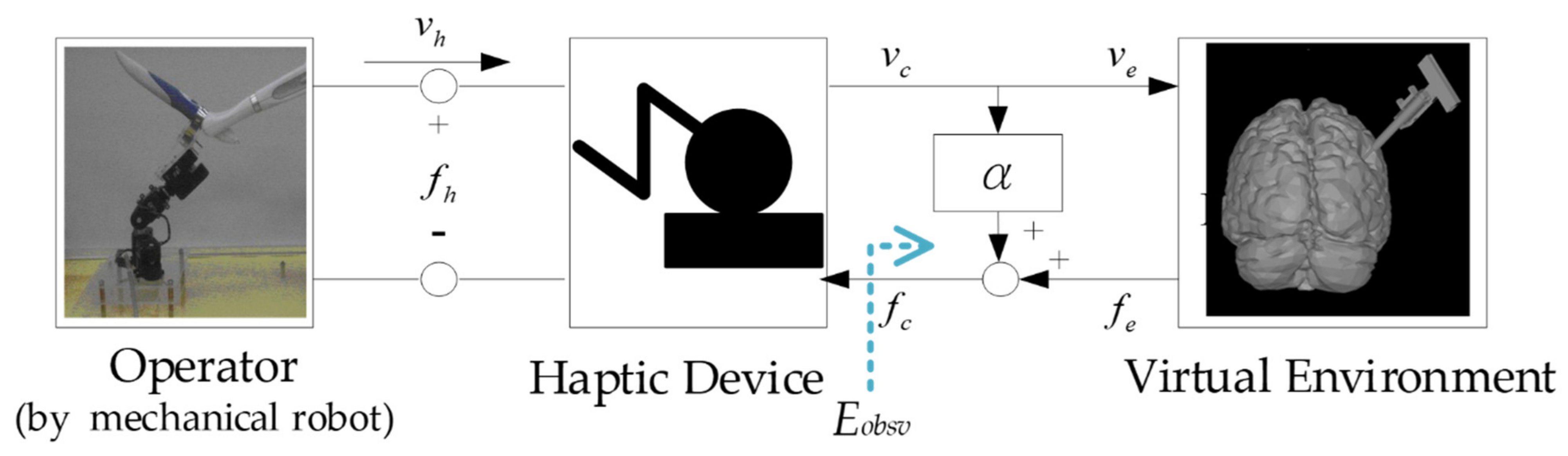
The framework of the IPC system is presented in
Figure 1, where
is the haptic device model,
is the zero-order holder (ZOH), and
and
are the IPC and VE models, respectively. In
Figure 1,
represents the displacement of the stylus,
represents the force of the human operator, and
and
represent the feedback forces from the VE and controller, respectively. Because the VE and controller were implemented with a personal computer, the associated discrete-time representations were used.
3. Planning and Design of Impedance-Passivity Controller (IPC)
3.1. Passivity Theorem
The passivity theorem is a stability analysis method based on the concept of energy dissipation, which can be applied to the stability analysis of nonlinear systems [
24]. The initial concept is based on the concept of circuitry, which is used in conjunction with the concept of a single-port network to discuss the energy relationship between the inflow and outflow of a system. As opposed to the definition of a circuit system, where current is the equivalent of voltage, passivity here means dissipation. In a simple circuit system with simple resistance and an applied voltage, the whole system consumes energy continuously and does not generate energy of its own. Such a circuit can be considered a circuit system possessing passivity. Energy dissipation is defined as follows.
Definition 1. The system will be a passive system because of the initial energy of the single-port network, which is expressed aswhere f is force (N). Definition 2. In a discrete-time system, if the system is a passive system at sampling time ΔT,
then the system has an initial energy,
which is expressed as In a haptic-feedback-based augmented reality system, the interactive mode has a two-port network architecture, as shown in
Figure 2. The system mainly consists of a human operator with a mechanical robot, a haptic device, an IPC and VE. Here,
is the force exerted by the operator,
is the operating speed,
is the speed of device movement in the VE,
is the applied force from the VE,
is the impedance-passivity controller (IPC),
is the combined force between the controller compensation and VE, and
is the system energy estimator.
According to the definition of passivity theorem,
:
By presenting the last term of (3), the general formula for calculating the energy of a virtual environment can be obtained, as shown in (4):
In accordance with definition 2, the controller design equation can be obtained:
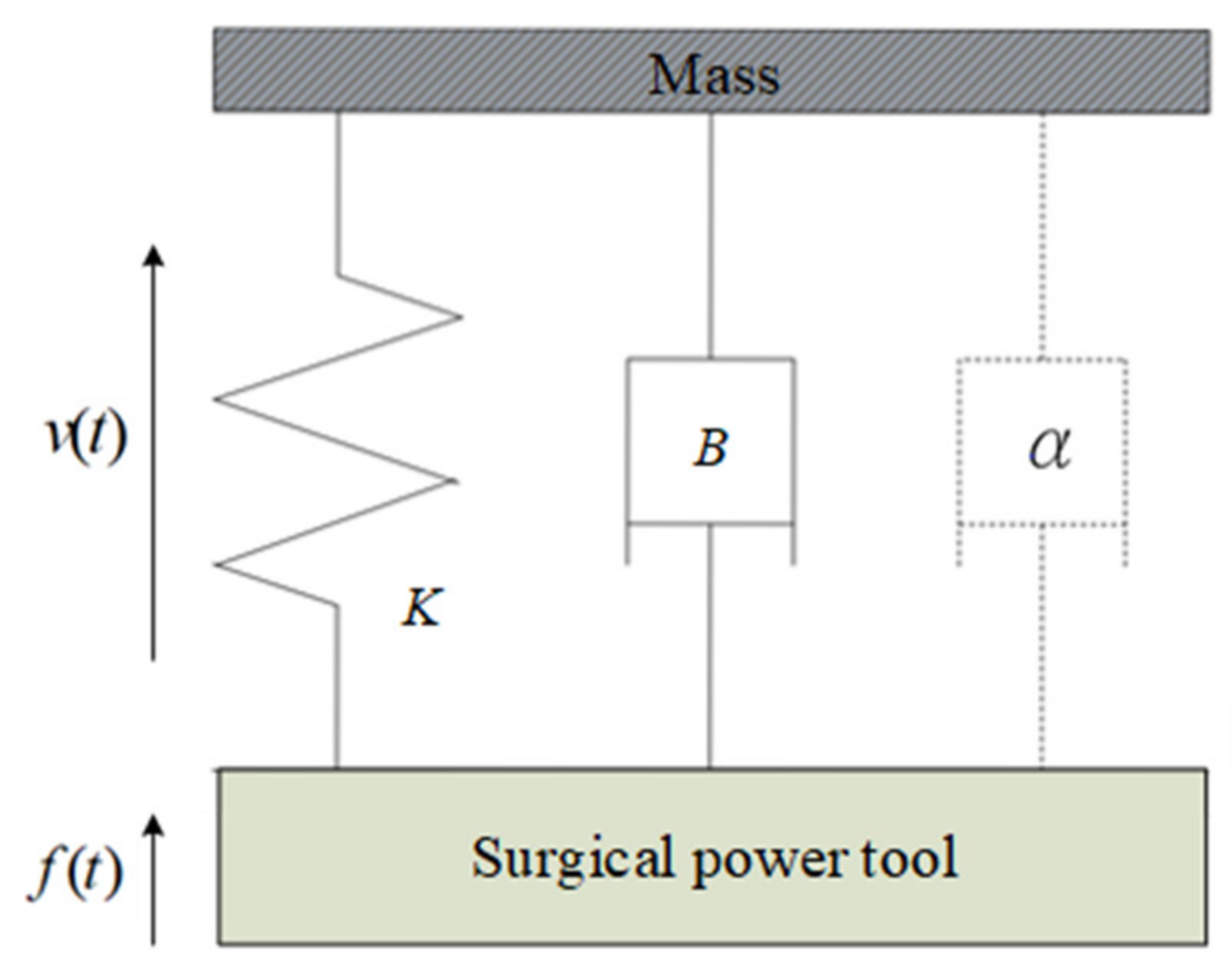
In this study, the
controller represents the physical meaning of an energy-expendable component that consumes the excess energy generated in the system, as shown in
Figure 3. Then,
Figure 3 is a schematic diagram of a virtual wall, where
and
are the damping and spring coefficient, respectively. Then
plays the role of a control parameter as described above.
Definition 3. For the sampling data system inFigure 1,
the system must dissipate energy if and only if the device and virtual environment parameters meet the following inequalities:where the sampling time is,
,
andare the system resonance frequency and damping coefficient of haptic device,
respectively. Finally,
is the Nyquist frequency.
3.2. Impedance Passivity Controller for Haptic Feedback
The mathematical models of the blocks of
Figure 1 are given as follows
in which
m is the mass, and
b is the damping coefficient of haptic device. For the discrete-time models,
T is the sampling period.
Let
H(
z) =
E(z) +
C(
z). It can be obtained that
Based on the passivity theorem addressed in [
20], it can be derived that the control scheme of
Figure 1 is passive if the following inequality holds
The last term of (10) can be rewritten as
Substituting (11) into (10), the stability condition can be obtained as
The (12) is maximized at
, leading to the following sufficient condition:
To achieve passive stability, this result shows that we can find the stable range of the controller parameter provided with the given values of and .
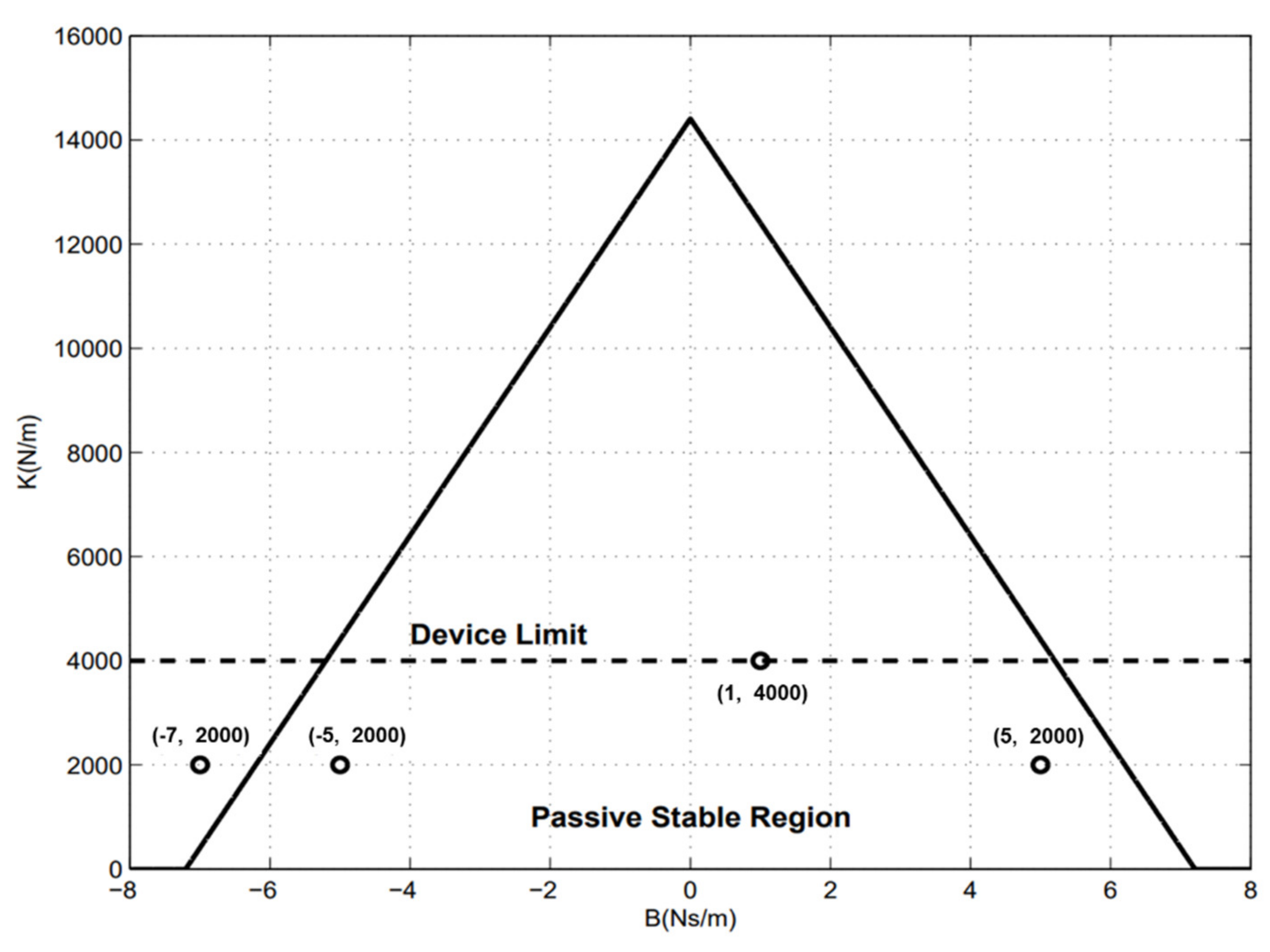
3.3. Passive Stable Region of Haptic Feedback
To obtain the stable passive region, some parameter identification processes needs to be performed. The mass and physical damping of the haptic device can be obtained by means of a least square algorithm [
25], and the identified values of the mass and damping of the haptic device are 0.0886 kg and 6.2036 Ns/m with a sampling period of 1 ms, respectively. Thus, from (13), a stable passivity region of VE parameters, i.e.,
K and
B, is shown in
Figure 4. In practice, due to the limitation of the haptic device, the maximum reaction force must be restricted. In this paper, the maximum stiffness constant
K is set to be 4000 N/m.
4. Experimental System and Integration Test of Haptic Stability
4.1. Framework Message Design
A typical haptic-based virtual training system was successfully developed and tested for passivity stability, according to the scheme presented in
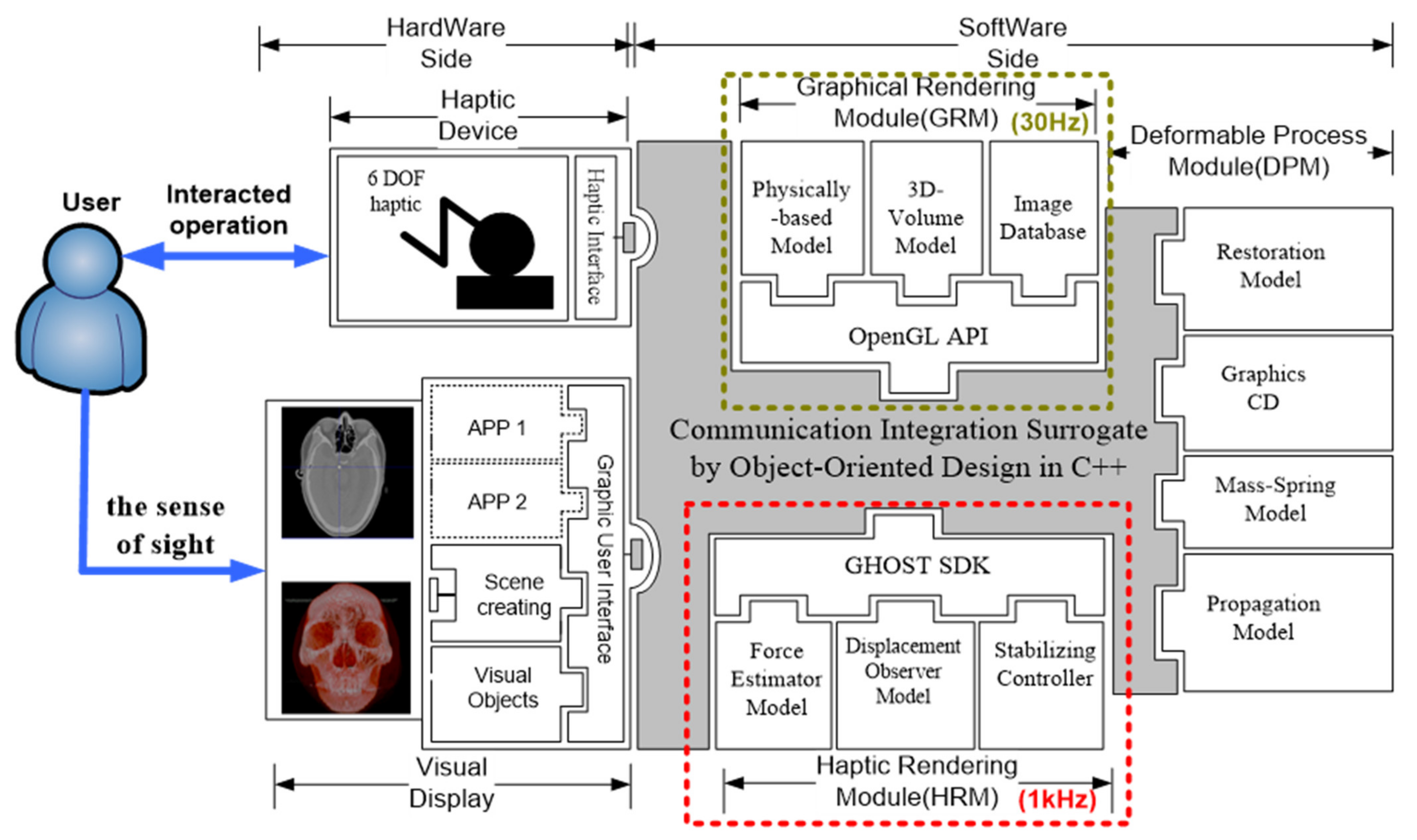
Figure 2. The framework was designed to present a computational process of deformation and tactile interaction to provide a realistic and stable virtual contact experience for the user. The system architecture can be roughly divided into two parts, namely the hardware and software parts. The hardware side includes the tactile device and visual display, whereas the software side includes the haptic rendering module (HRM), deformable process module (DPM), and graphical rendering module (GRM).
The system must clearly define the framework messages, especially the communication messages among various system components, to finalize a solution that can support a particular application. A physically-based image is loaded into the system as a deformable object for display. When collisions occur between virtual objects, nodes of the virtual objects are assigned to DPMs by the GRM. Therefore, the GRM also performs graphical refreshing to update the position of the virtual pen on the visual display and the deformation status of the visual object.
We developed the HRM through point-based haptics, with the device’s stylus tip being modeled as a haptic contact and interaction with the virtual object. The degree of virtual object deformation or depth in the virtual environment is obtained using the DPM’s propagation model. In the present framework, the force between the visual object and the virtual probe is calculated using the displacement observers of the HRM. Subsequently, the HRM converts the position and surface information into a torque command vector, which is transmitted to the drive motor of the PHANToM unit through the stability controller to provide stable force feedback.
Finally, to provide realistic force feedback, a multirate simulation technique is used to ensure that one runs at the visual update rate (at 30 Hz) and the other runs at the tactile update rate (at least 1 kHz). Through frame information processing, human hand motions could be efficiently mapped to the correct virtual probe positions in the experimental system.
4.2. Experimental Platform
The SensAble PHANToM Omni was treated as a haptic device in this study. The system was implemented on an PC running Windows 10 Enterprise Edition, with Intel Xeon E5-2678 v3, 64 GB DDR4 RAM, and a 1124 MB NVIDIA GeForce GTX 1080 Ti as the graphics card. The haptic feedback is provided by the SensAble PHANToM Omni, which has a maximum force output of 3.3 N (Newton) and has six degrees of freedom for position and orientation sensing. As shown in
Figure 5, the experimental platform was successfully constructed by using Microsoft C++, GLUT, and MFC. In addition, graphic visualization and haptic rendering were also implemented through the OpenGL and PHANToM Omni Library, respectively. Through the above introduction, the proposed impedance-passivity method is added to this study to provide the implementation of stability haptic feedback.
4.3. Simulation and Integration Test of Experiment System
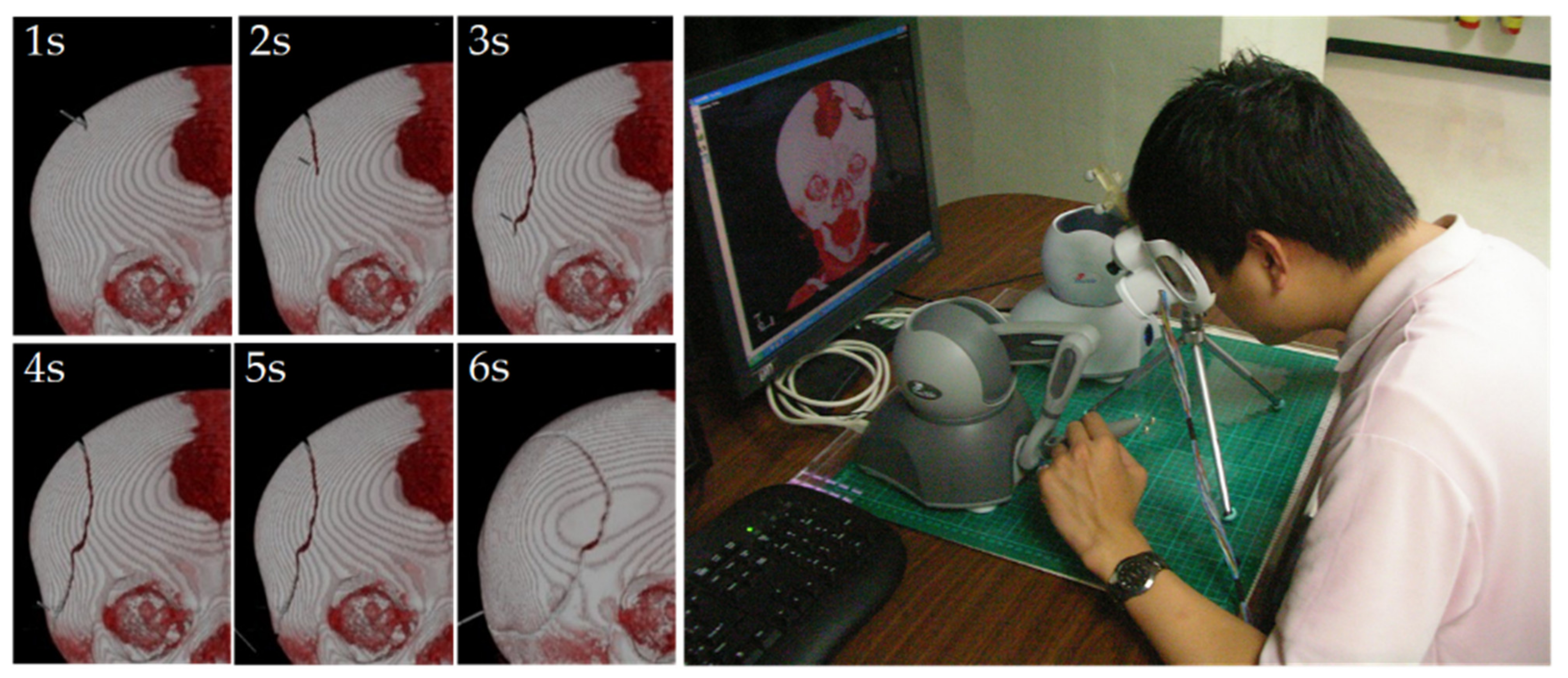
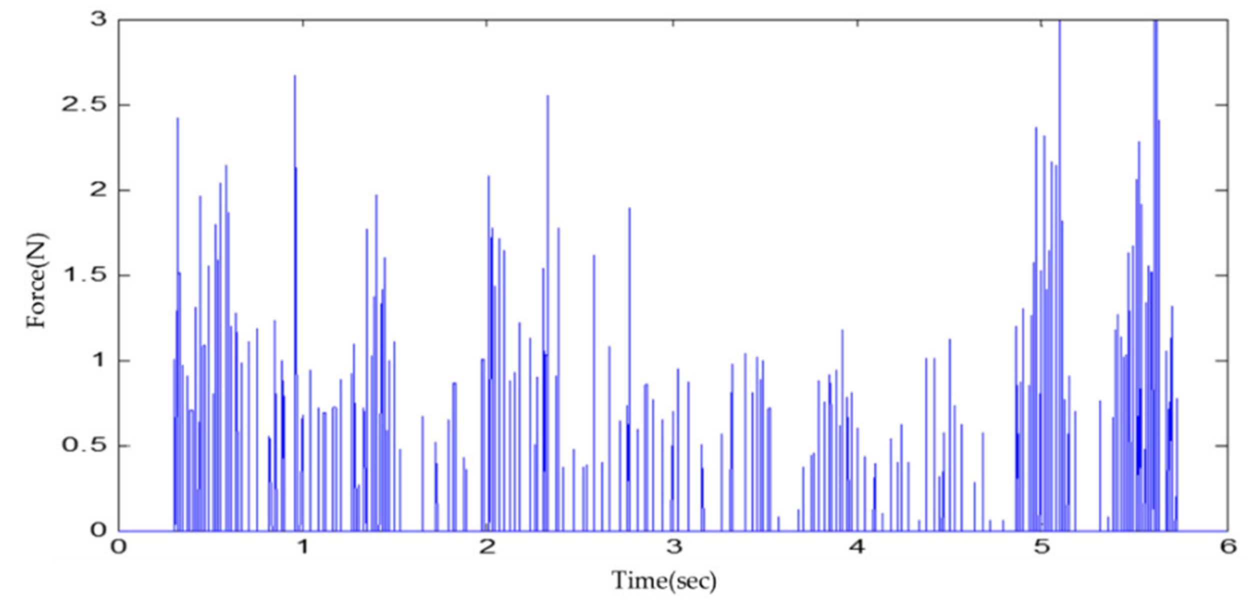
To achieve the purpose of simulating a real system, this study used 3D volume rendering to generate the shadow volume image of the skull. Without loss of generality, the material properties were set to be the same; the associated skull remodeling simulations and reaction force feedback are shown in
Figure 6 and
Figure 7. After manipulation by the medical professionals, it was believed that the reaction force and the volume model formed a satisfactory circular effect. In addition, when a user operated the haptic device in our tests, the virtual system calculated the corresponding distance, correctly touched the virtual knife to the virtual skull, and gave the force feedback to the haptic device in real time. The haptic stability is especially focused on the effects of high stiffness and negative damping, and the trade-off between the fidelity and stability can be easily achieved under the passive analysis criterion in the one-dimensional sticking. Finally, a haptic-based virtual surgical simulation system was constructed and optimized as a stability-controlled experimental platform.
4.4. Hardware Platform for One-Degree-of-Freedom Sticking
In general, the communication delay between the VE and the haptic device will cause a possible stability demotion. Since the proposed scheme is performed under local operation, the delay effect is neglected. In addition, the sampling frequency was set as 1 kHz, and thus the influence of numerical error can be ignored as well. In this paper, the haptic stability is focused on the effects of high stiffness and negative damping.
To keep the experiments consistent so that we can repeatedly study a comparison of the performance, a motor-driven mechanism was implemented to replace the manual operation. The command signals were sent from the graphical user interface designed using Visual Basic, Visual Studio 2015. In addition, to ensure device usability, according to the specifications of the haptic device, an overload protection function was also considered such that any abnormal action will be stopped if the system overload is detected. The experiment platform, integrated with hardware and software modules, for the task of one-DOF sticking, is shown in
Figure 8.
5. Experimental Results
The mentioned haptic stability is verified with three cases of tests, i.e., positive damping, negative damping, and high stiffness. Experiment results of the stylus position, feedback force from the virtual environment, and feedback force from the controller are recorded. With the proposed damping controller, the improvement of haptic rendering will be illustrated in the following subsections.
5.1. Case I: Positive Damping
The experiment results are shown in
Figure 9, where
= 2000 N/m and
= 5 Ns/m inside the stable passive region. In
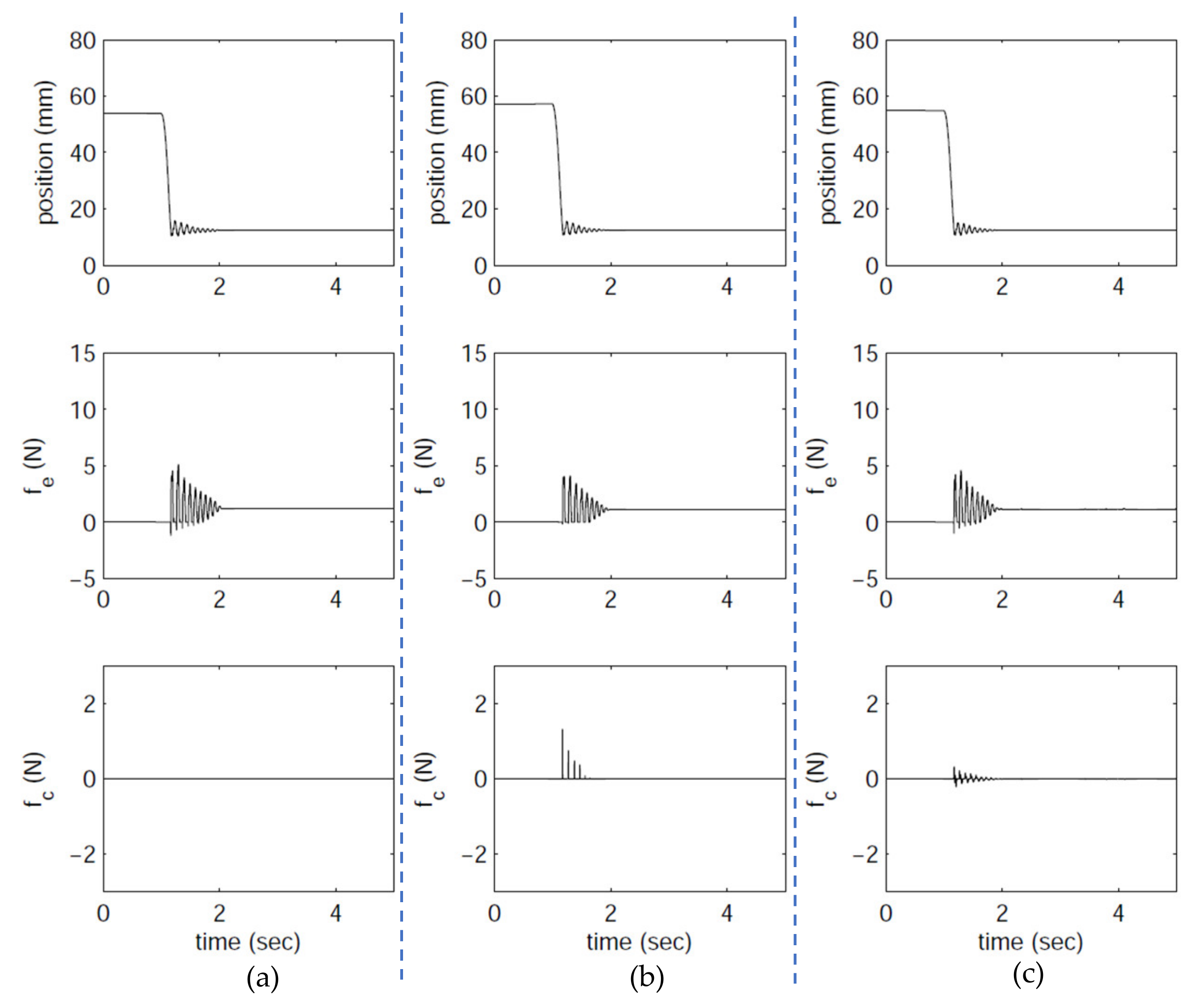
Figure 9, the responses from top to bottom are the stylus position of the haptic device, the force feedback from VE, and the compensating force from controller, respectively. We set up the initial probe position to be at 55 mm. In addition, the surface position of virtual object was at 12 mm, and the starting instant was set at 1 s. When the tip of the visual surgical knife touches the surface of a visual object, the VE calculates the displacement and velocity of the virtual object and returns the force to the haptic device. The motor-driven mechanism plays a role like a human operator, providing an external force for haptic interaction. From
Figure 4, since the parameter setting was already in the passive region, the haptic system achieved stable equilibrium after about 4 bounces with or without the controller.
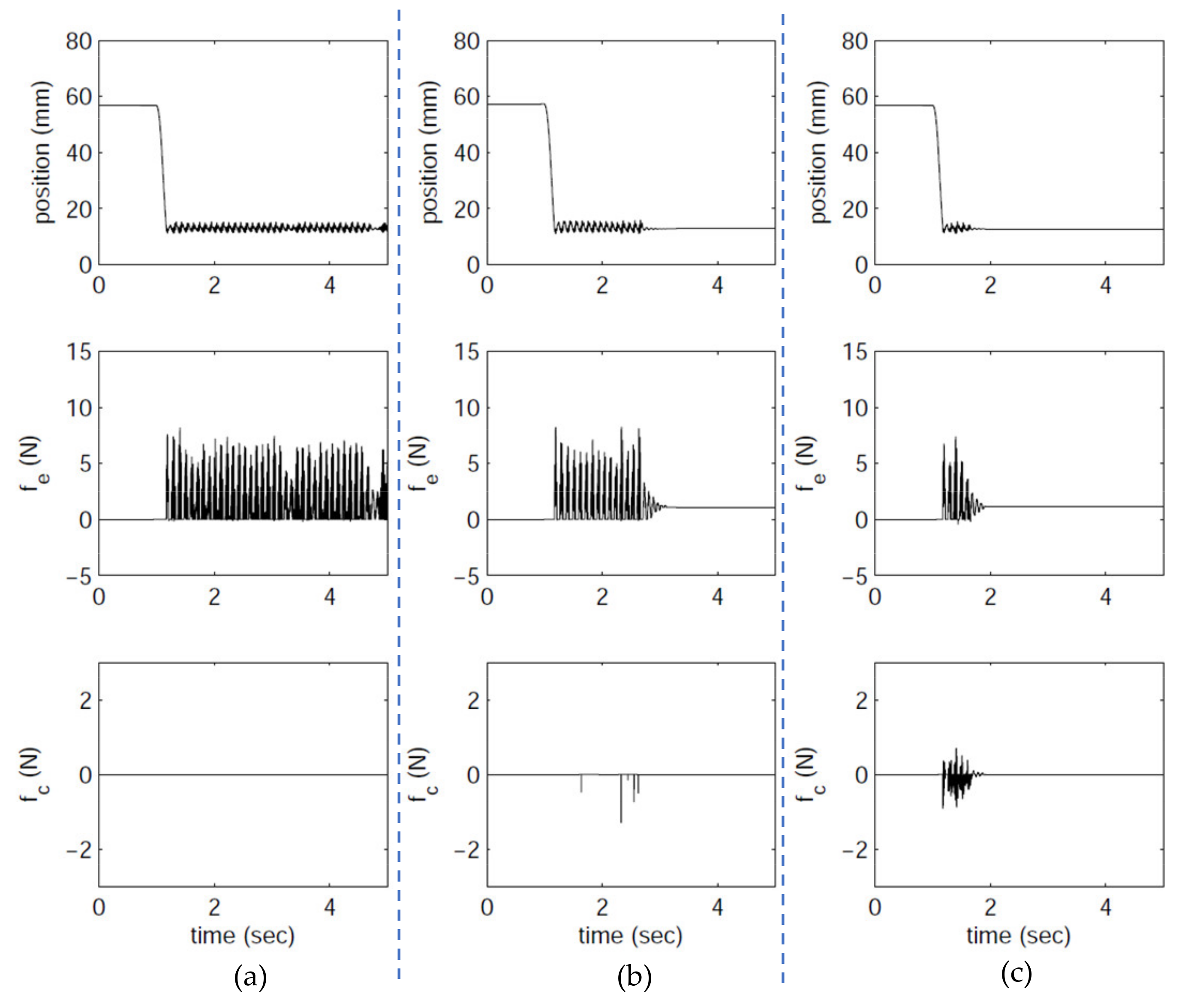
5.2. Case II: Negative Damping
In this second case, a negative damping situation was considered, with
= 2000 N/m and
= −5 Ns/m. From
Figure 10, the parameter setting was still inside the passive region. However, with negative damping, the virtual environment was active, and a reactive force was produced from the VE even when the stylus moved away from the object surface. Thus, it can be expected that it needs more time to reach the stabilizing equilibrium. From
Figure 10, it can be observed that the proposed IPC provided some compensating force, and the oscillation behavior of stylus position was slightly improved. The reason why the improvement was not so significant is that the parameter setting is still in a relatively stable passive region. To highlight the effectiveness of the proposed IPC, another negative damping case is addressed, i.e.,
= 2000 N/m and
= −7 Ns/m. From
Figure 4, this new setting was outside the passive region, and thus the nominal operation was unstable.
Figure 11 illustrates the responses for the cases of
= −7 Ns/m. It is obvious that with the proposed controller, the oscillation phenomenon was significantly reduced.
5.3. Case III: High Stiffness
From
Figure 4, the maximum stiffness is 14,200 N/m in order to stay in the passive stable region. However, due to the force limitation of the haptic device, the maximum allowable stiffness was set to be
= 4000 N/m, representing the characteristics of hard objects. From
Figure 4, the case of
= 4000 N/m and
= 1 Ns/m is in the boundary of the stable region. Interestingly, from
Figure 12, it is shown that a high stiffness setting did cause instability, where the stylus position continuously bounced up and down. With the proposed controller, the oscillation behavior was eliminated in 1 s, and the effectiveness of proposed scheme was clarified.
Table 1 displays the summary of the time needed to reach the stabilizing equilibrium for all cases. In this study, the IPC was used to select the available controller parameters in the stability range through a prestabilization analysis. In a DOF adhesion, it is clearly observed that the IPC starts compensating the system upon entering the virtual environment. Thus, the effect of feedback and energy convergence can be achieved quickly and steadily, while ensuring that the haptic feedback generated by the controller parameters does not exceed the hardware limits of the device. It is clear from
Table 1 that the addition of the IPC to the haptic system does reach stability faster than a controller-less system and a basic-passivity controller in the cases of negative damping coefficients and high stiffness constants, respectively. Finally, it can be demonstrated from the experimental results that the proposed IPC in this study fully meets the research objectives.
6. Conclusions
On the basis of energy concepts, we developed a passivity theorem to study the stability of force feedback in a virtual haptic system. The proposed scheme was implemented to enable real-time interactive operation and integrate haptic technology with guaranteed stability. In addition, a virtual training system for one-DOF sticking was developed to validate the experimental platform of our developed IPC. Moreover, to ensure consistency in the experiment, we designed a specialized mechanical robot to replace human operation. The experimental results indicated that compared with systems with basic passivity, the proposed IPC could achieve stable control rapidly. Practitioners and haptic system designers may find the results of this paper useful. Our future work will focus on three-dimensional interactive operations and other surgical simulation applications.
Although the IPC could dissipate excess energy in the virtual environment to stabilize the system, the parameter values of the haptic device and VE must be predetermined. Accordingly, relevant future work can improve the controller by incorporating adaptive control concepts such neural fuzzy control. Optimal controller parameters can be identified to determine the force penetration depth of the haptic device with a prespecified analytical design for system energy dissipation.
Author Contributions
R.-J.C. performed the experiments; Y.-T.C. performed the analysis and wrote the paper; P.-N.C. and H.H. provided the design of the work, and oversaw the final approval of the version to be published; all authors discussed the results, analyzed the data, and commented on the manuscript. All authors have read and agreed to the published version of the manuscript.
Funding
This research received no external funding.
Institutional Review Board Statement
Not applicable.
Informed Consent Statement
Not applicable.
Data Availability Statement
Not applicable.
Acknowledgments
The current study was supported by grants from Ministry of National Defense-Medical Affairs Bureau (MAB-109-083).
Conflicts of Interest
The authors declare no conflict of interest.
References
- Basdogan, C.; Srinivasan, M.A. Haptic Rendering in Virtual Environments, Handbook of Virtual Environments: Design, Implementation, and Applications—Human Factors and Ergonomics; Stanney, K., Ed.; Lawrence Erlbaum Associates: Mahwah, NJ, USA, 2002; pp. 117–134. [Google Scholar]
- Palmerius, K.L.; Cooper, M.; Ynnerman, A. Haptic rendering of dynamic volumetric data. IEEE Trans. Vis. Comput. Graph. 2008, 14, 263–276. [Google Scholar] [CrossRef] [PubMed]
- Lee, S.; Kim, G.J.; Choi, S. Real-time tracking of visually attended objects in virtual environments and its application to LOD. IEEE Trans. Vis. Comput. Graph. 2009, 15, 6–19. [Google Scholar] [PubMed]
- Shuxiang, G.; Yu, S.; Xuanchun, Y.; Linshuai, Z.; Takashi, T.; Hideyuki, H.; Hidenori, I. A novel robot-assisted endovascular catheterization system with haptic force feedback. IEEE Trans. Robot. 2019, 35, 685–696. [Google Scholar]
- Overtoom, E.M.; Horeman, T.; Jansen, F.W.; Dankelman, J.; Schreuder, H.W.R. Haptic feedback, force feedback, and force-sensing in simulation training for laparoscopy: A systematic overview. J. Surg. Educ. 2019, 76, 242–261. [Google Scholar] [CrossRef]
- Guo, S.; Wang, Y.; Xiao, N.; Li, Y.; Jiang, Y. Study on real-time force feedback for a master-slave interventional surgical robotic system. Biomed. Microdevices 2018, 20, 37. [Google Scholar] [CrossRef] [PubMed]
- Otaduy, M.A.; Lin, M.C. A modular haptic rendering algorithm for stable and transparent 6-DOF manipulation. IEEE Trans. Robot. 2006, 22, 751–762. [Google Scholar] [CrossRef]
- Ortega, M.; Redon, S.; Coquillart, S. A six degree-of-freedom god-object method for haptic display of rigid bodies with surface properties. IEEE Trans. Vis. Comput Graph. 2007, 13, 458–469. [Google Scholar] [CrossRef]
- Stetten, G.; Wu, B.; Klatzky, R.; Galeotti, J.; Siegel, M.; LEE, R.; Mah, F.; Eller, A.; Schuman, J.; Hollis, R. Hand-held force magnifier for surgical instruments. In Proceedings of the 2nd International Conference on Information Processing in Computer-Assisted Interventions, Berlin, Germany, 22 June 2011; pp. 90–100. [Google Scholar]
- Barbagli, F.; Salisbury, K. The effect of sensor/actuator asymmetries in haptic interfaces. In Proceedings of the IEEE Symposium on Haptic Interfaces for Virtual Environment and Teleoperator Systems, Los Angeles, CA, USA, 22–23 March 2003; pp. 140–147. [Google Scholar]
- Heng, P.A.; Wong, T.T.; Yang, R.; Chui, Y.P.; Xie, Y.M.; Leung, K.S.; Leung, P.C. Intelligent inferencing and haptic simulation for chinese acupuncture learning and training. IEEE Trans. Inf. Technol. Biomed. 2006, 10, 28–41. [Google Scholar] [CrossRef] [PubMed]
- Ferraguti, F.; Preda, N.; Manurung, A.; Bonfe, M.; Lambercy, O.; Gassert, R.; Muradore, R.; Fiorini, P.; Secchi, C. An energy tank-based interactive control architecture for autonomous and teleoperated robotic surgery. IEEE Trans. Robot. 2015, 31, 1073–1088. [Google Scholar] [CrossRef]
- Menaker, S.A.; Shah, S.S.; Snelling, B.M.; Sur, S.; Starke, R.M.; Peterson, E.C. Current applications and future perspectives of robotics in cerebrovascular and endovascular neurosurgery. J. NeuroInterventional Surg. 2018, 10, 78. [Google Scholar] [CrossRef] [PubMed]
- Bucolo, M.; Buscarino, A.; Fortuna, L.; Gagliano, S. Force Feedback Assistance in Remote Ultrasound Scan Procedures. Energies 2020, 13, 3376. [Google Scholar] [CrossRef]
- Diolaiti, N.; Niemeyer, G.; Barbagli, F.; Salisbury, J.K. Stability of haptic rendering: Discretization, quantization, time delay, and Colomb effects. IEEE Trans. Robot. 2006, 22, 256–268. [Google Scholar] [CrossRef]
- Katsura, S.; Matsumoto, Y.; Ohnishi, K. Modeling of force sensing and validation of disturbance observer for force control. IEEE Trans. Ind. Electron. 2007, 54, 530–538. [Google Scholar] [CrossRef]
- Katsura, S.; Irie, K.; Ohishi, K. Wideband force control by position acceleration integrated disturbance observer. IEEE Trans. Ind. Electron. 2008, 55, 1699–1706. [Google Scholar] [CrossRef]
- Colgate, J.; Schenkel, G.G. Passivity of a class of sample-data system: Application to haptic interface. Robot. Syst. 1997, 14, 37–47. [Google Scholar] [CrossRef]
- Weir, D.W.; Colgate, J.E.; Peshkin, M.A. Measuring and increasing Z-width with active electrical damping. In Proceedings of the International Symposium on Haptic Interfaces, Reno, NV, USA, 13–14 March 2008; pp. 169–175. [Google Scholar]
- Hulin, T.; Preusche, C.; Hirzinger, G. Stability boundary for haptic rendering: Influence of human operator. In Proceedings of the IEEE/RSJ International Conference on Intelligent Robots and Systems, Nice, France, 22–26 September 2008; pp. 3483–3488. [Google Scholar]
- Hannaford, B.; Ryu, J. Time-domain passivity control of haptic interfaces. IEEE Trans. Robot. Autom. 2002, 18, 1–10. [Google Scholar] [CrossRef]
- Ryu, J.H.; Kim, Y.S.; Hannaford, B. Sample and continuous time passivity and stability of virtual environments. IEEE Trans. Robot. 2004, 20, 772–776. [Google Scholar] [CrossRef]
- Ryu, J.H.; Hannaford, B.; Preusche, C.; Hirzinger, G. Time domain passivity control with reference energy following. IEEE Trans. Control. Syst. Technol. 2005, 13, 737–742. [Google Scholar]
- Marquez, H.J. Nonlinear Control Systems: Analysis and Design; John Wiley & Sons: Hoboken, NJ, USA, 2003. [Google Scholar]
- Franklin, G.F.; Powell, J.D.; Workman, M. Digital Control of Dynamic Systems, 3rd ed.; Addison Wesley Longman Inc.: Menlo Park, CA, USA, 1998; pp. 502–510. [Google Scholar]
Figure 1.
Framework of the impedance-passivity controller.
Figure 1.
Framework of the impedance-passivity controller.
Figure 2.
Block diagram of haptic feedback based augmented reality.
Figure 2.
Block diagram of haptic feedback based augmented reality.
Figure 3.
Schematic diagram of a virtual wall.
Figure 3.
Schematic diagram of a virtual wall.
Figure 4.
Region of passive stability.
Figure 4.
Region of passive stability.
Figure 5.
Framework message of the experiment system.
Figure 5.
Framework message of the experiment system.
Figure 6.
Simulation and integration test of experiment system. The time is 1–6 s from left to right, respectively.
Figure 6.
Simulation and integration test of experiment system. The time is 1–6 s from left to right, respectively.
Figure 7.
Skull remodeling simulations and reaction force feedback corresponding to
Figure 6.
Figure 7.
Skull remodeling simulations and reaction force feedback corresponding to
Figure 6.
Figure 8.
Experimental platform for task of one-dimensional sticking.
Figure 8.
Experimental platform for task of one-dimensional sticking.
Figure 9.
Experimental results at = 2000 N/m, = 5 Ns/m, α = −1 Ns/m: (a) controller free, (b) the basic passivity controller, and (c) the impedance-passivity controller (IPC).
Figure 9.
Experimental results at = 2000 N/m, = 5 Ns/m, α = −1 Ns/m: (a) controller free, (b) the basic passivity controller, and (c) the impedance-passivity controller (IPC).
Figure 10.
Experimental results at = 2000 N/m, = −5 Ns/m, α = 1 Ns/m: (a) controller free, (b) the basic passivity controller, and (c) the IPC.
Figure 10.
Experimental results at = 2000 N/m, = −5 Ns/m, α = 1 Ns/m: (a) controller free, (b) the basic passivity controller, and (c) the IPC.
Figure 11.
Experimental results at = 2000 N/m, = −7 Ns/m, α = 3 Ns/m: (a) controller free, (b) the basic passivity controller, and (c) the IPC.
Figure 11.
Experimental results at = 2000 N/m, = −7 Ns/m, α = 3 Ns/m: (a) controller free, (b) the basic passivity controller, and (c) the IPC.
Figure 12.
Experimental results at = 4000 N/m, = 1 Ns/m, α = 1 Ns/m: (a) controller free, (b) the basic passivity controller, and (c) the IPC.
Figure 12.
Experimental results at = 4000 N/m, = 1 Ns/m, α = 1 Ns/m: (a) controller free, (b) the basic passivity controller, and (c) the IPC.
Table 1.
Summary of the time needed to reach the stabilizing equilibrium for all cases.
Table 1.
Summary of the time needed to reach the stabilizing equilibrium for all cases.
| Experiment | Controller |
|---|
| Free (s) | Basic Passivity (s) | Impedance Passivity (s) |
|---|
Case I: positive damping
( = 2000 N/m, = 5 Ns/m, α = −1 Ns/m) | | 0.45 | 0.32 | 0.43 |
Case II: negative damping
( = 2000 N/m, = −7 Ns/m, α = 3 Ns/m) | | 3.12 | 1.33 | 1.16 |
Case III: high stiffness
( = 4000 N/m, = 1 Ns/m, α = 1 Ns/m) | | >4 | 2.10 | 0.91 |
| Publisher’s Note: MDPI stays neutral with regard to jurisdictional claims in published maps and institutional affiliations. |
© 2021 by the authors. Licensee MDPI, Basel, Switzerland. This article is an open access article distributed under the terms and conditions of the Creative Commons Attribution (CC BY) license (http://creativecommons.org/licenses/by/4.0/).


