Article

Effects of Bulk Flow Pulsations on Film Cooling with Two Sister Holes

School of Mechanical Engineering, Kookmin University, Seoul 02707, Korea
*
Author to whom correspondence should be addressed.
Appl. Sci. 2021, 11(4), 1537; https://doi.org/10.3390/app11041537
Submission received: 31 December 2020 / Revised: 29 January 2021 / Accepted: 3 February 2021 / Published: 8 February 2021

Abstract

:
In a triple-hole system comprising a primary hole and two sister holes, when the sister holes are positioned slightly downstream of the main hole under steady flow conditions, their jets generate an anti-counter-rotating vortex pair. Vortex interactions between the jets increase the effectiveness of adiabatic film cooling. In this study, a series of large-eddy simulations were conducted to understand how pulsations in the main flow affect film cooling in a triple hole. To understand the effects of pulsations on film cooling performance is important for better cooling design of the gas turbine engines. The numerical simulations were carried out on a flat plate geometry with a triple cylindrical hole system at 35° injection angle. The pulsations were approximately sinusoidal, and their effect on film cooling was investigated at several frequencies (2, 16, and 32 Hz) and Strouhal numbers (Sr = 0.1005, 0.8043, and 1.6085) at an average blowing ratio of 0.5. The results for the triple-hole system were compared with those for a single hole for the same amount of cooling air and the same cross-sectional area of the holes. Increasing the Strouhal number of the main flow decreased η in both systems. However, at each Strouhal number, η was higher in the triple hole. Furthermore, the triple-hole system was found to be better for film cooling than a single-hole system for higher values of the pulsation Strouhal number. Contours of time-averaged film cooling effectiveness and dimensionless temperature, instantaneous film cooling effectiveness contours on a test plate, mean velocity magnitude contours in the hole, and Q-contours for the triple holes under the application of pulsations to the flow were investigated.

1. Introduction

The efficiency of the gas turbine can be improved by raising the inlet temperature [1]. However, the turbine blade temperature should remain below the acceptable limit [2]. Film cooling is a widely used in gas turbines [3]. The physics of film cooling under a steady main flow has been widely investigated. Especially, intended vortex interactions could be induced between cooling jets by using specific cooling hole arrangements instead of the single hole. Heidmann et al. [4] numerically showed that compared with a one-hole system, the use of three holes (a primary hole and two side holes) increased the film cooling effectiveness at M = 1.0. They also reported that manufacturing triple cylindrical holes was more economical than manufacturing holes with other shapes. Using square sister holes, Javadi et al. [5] controlled the vortex interactions between injectant and main flow at the blowing ratio, M of 0.5. They numerically found that two sister holes reduced the mixing between the coolant injectant and the crossflow, thereby increasing η. Ely et al. [6] numerically investigated the increase in η after forming two sister holes [3]. They varied the blowing ratio among the values 0.2, 0.5, 1.0, and 1.5 and reported an obvious improvement in η at high M. Choi et al. [7] numerically investigated performance of the film cooling for double holes by changing design variables such as the lateral ejection angles and streamwise and lateral distances between the holes. They found that the lateral distance and lateral ejection angles significantly influenced the film cooling performance while the effect of the streamwise distance on the film cooling effectiveness was considerably less. Wu et al. [8] determined the cooling performance of three types of sister hole configurations by using experimental and numerical methods. They stated that the effectiveness of the film cooling was considerably higher for the triple-hole configurations compared with that for a single-hole configuration under steady flow conditions.
However, in real flow fields, the mainstream flow could be unsteady. It could be disturbed by many reasons such as potential flow interactions, and freestream turbulence generated in the combustor or passing wakes [9]. The effect of flow instabilities on the film cooling performance for the triple hole system has not been studied. Understanding the effect of main flow pulsation on the film cooling for the triple holes would help for making better cooling design of the gas turbine engines. Kim et al. [10] observed that most previous computational fluid dynamics (CFD) studies on film cooling had been conducted under steady flow conditions. Few studies have considered the effect of pulsations, caused by flow instabilities, in the main flow. Gau et al. [11] experimentally studied the effect of swirling flow in mainstream flow on η. They showed that if the swirling number, which represents the axial flux of the swirl momentum, is increased, η decreases due to improved mixing between the main flow and cooling jet. Coulthard et al. [12] studied the film cooling effect of a pulsating injectant by using experimental method, and they reported that steady coolant injection maximized η [2]. When the coolant injection was pulsed, η reduced with increase of Strouhal number at M = 0.5.
Nikitopoulos et al. [13] reported that coolant pulsation can control the film cooling performance. To understand the physics in the pulsed film-cooling flow field, researchers have investigated the optimal parameter range of coolant pulsation. Ekkad et al. [14] experimentally studied the effect of cooling jet pulsation on the film cooling in a turbine blade model. They found that jet propulsion weakened the jet liftoff at high blowing ratios, increasing the spread of the coolant on the wall. However, when the main flow velocity is disturbed by flow interactions, shock waves, turbulence generated in the combustion chamber, or passing shock waves on the turbine blade, the disturbance patterns are more similar to sinusoidal waves than pulses [9]. In an experimental study, Seo et al. [9] showed how sinusoidal mainstream pulsations influence film cooling. They reported that for a small L/D ratio, increasing the pulsation frequency from 0 to 32 Hz at the blowing ratio, M of 0.5 decreased the adiabatic film cooling effectiveness and increased the iso-energetic Stanton number ratio. Gao et al. [15] reported the effect of vane passage vortex generation on film cooling by using a pressure-sensitive paint. The strength of the vortex was adjusted by changing the attack angle of the main flow to the delta wing. They found that a stronger vortex resulted in increased the mixing, leading to a decreasing η.
Xiao et al. [16] showed a fractal solution to study the Kozeny-Carman constant and permeability for fibrous porous media. They stated that if the particle diameter was increased, the absolute permeability was increased and if the tortuosity fractal dimension was increased, the Kozeny-Carman constant was increased, however, the dimensionless permeability was decreased. Liang et al. [17] proposed that a fractal theory of porous media in order to quantify the porous media’s effective electrolyte diffusivity. The analytical results showed a good match with the experimental data.
In this study, an analysis was performed using a large-eddy simulation (LES). Although a LES incurs higher computational cost than Reynolds-averaged Navier–Stokes (RANS), the RANS approach cannot accurately predict complex flow interactions because it involves ensemble-averaging the turbulent fluctuations in the flow. By contrast, the LES approach resolves large-scale turbulent eddies, enabling accurate predictions of complex flows [2,18]. Johnson et al. [19] found that an LES model showed considerably more spreading of the coolant jet compared with RANS turbulence models and that the LES results were similar to real film cooling fields. Baldauf et al. [20] found that at the low blowing ratios, the effectiveness of the film cooling decreased rapidly as the coolant travelled downstream, despite high film cooling effectiveness around the cooling hole. This can be attributed to the small mass flow rate of the coolant. Furthermore, low blowing ratios cause the detrimental ingestion of the hot mainstream gas into the hole [9,21]. Bogard [22] reported that the overall film cooling effectiveness increases with the blowing ratio up to the blowing ratio of 0.6. He observed that when the blowing ratio exceeds 0.85, the overall effectiveness decreases because of the separation of the coolant jet from the wall. Therefore, in this study, the average blowing ratio was fixed at 0.5. A sinusoidal pulsation in the main flow causes the difference between the static pressures around the inlet and the exit of the hole to oscillate, which in turn makes the coolant jet oscillate. Therefore, in the current study, a sinusoidal waveform was simultaneously applied to the main flow inlet and the plenum inlet with the same frequency.
By performing an LES, the current study investigated the effect of oscillating the main flow at various Strouhal numbers on film cooling with cylindrical triple holes on a flat plate. The numerical results were compared with the numerical and experimental results for a single cylindrical hole on a flat plate. As a baseline, the effect of the main flow pulsation on contours of film cooling effectiveness and dimensionless temperature was first investigated for single-hole and triple-hole systems. Next, the time-averaged effectiveness of the film cooling was compared between these two systems. Instantaneous contours of η on the wall were also investigated. Contours of the time-averaged velocity magnitude in the cooling hole were compared between the single-hole and triple-hole systems. Finally, Q-criterion iso-surfaces were compared and studied. The pulsations were sinusoidal, and the Strouhal number, non-dimensional frequency ranged from 0 to 1.6085. These numbers matched the pulsation frequency range of Seo et al. [9], allowing a comparison with their experimental results.

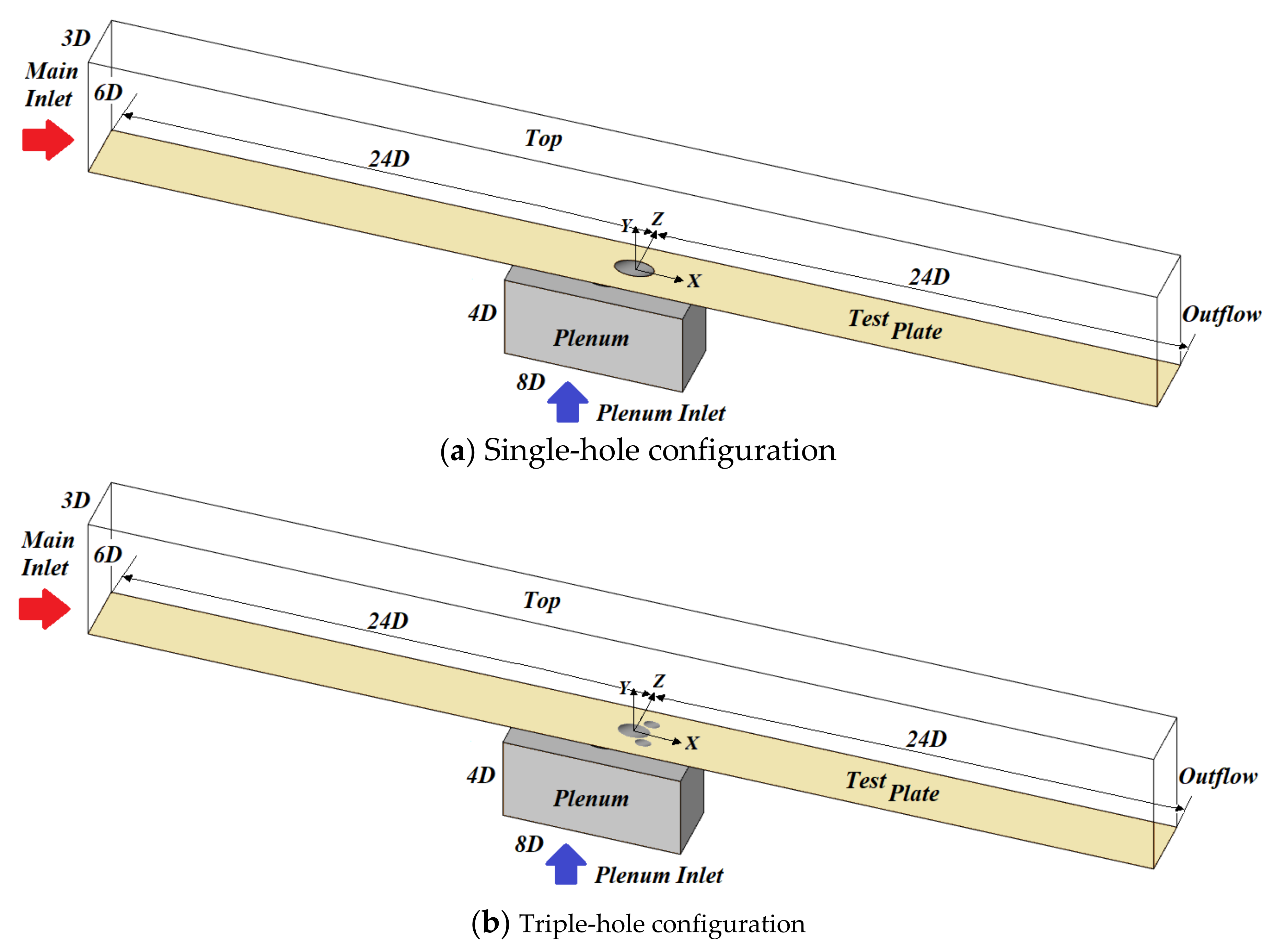
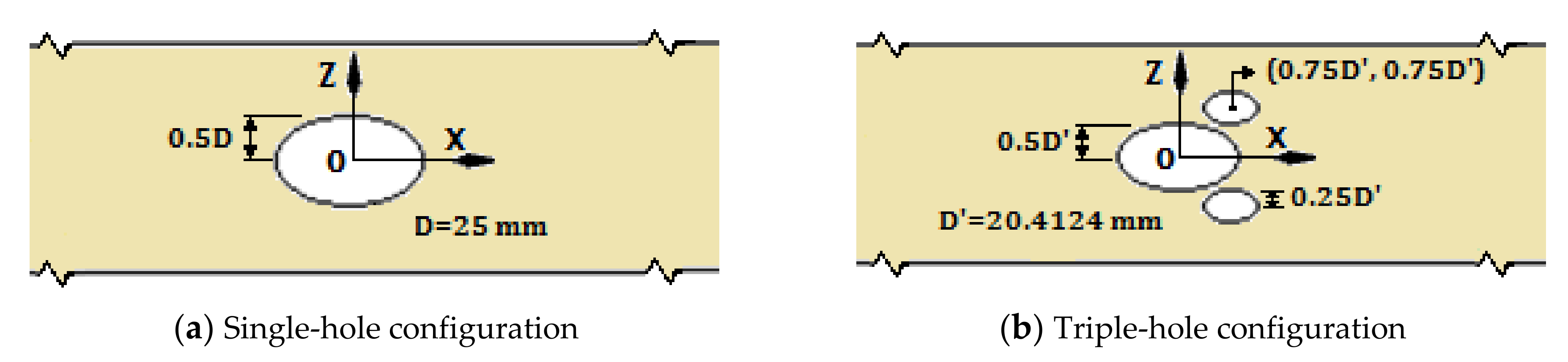
2. Geometry, Boundary Conditions

The geometry of the single-hole system, which was considered as the baseline, was obtained from the investigation of Seo et al. [9]. In their experimental apparatus, five cooling holes were positioned along a row. Here, the computational cost was reduced by applying periodic boundary conditions on the sidewalls [3]. The computational domains are displayed in Figure 1. Figure 2 presents schematics of the cooling holes in each case.
The triple holes consisted of two small holes located downstream of main hole (Figure 2b), as stated by Ely et al. [6]. In the triple-hole configuration, D of the primary hole and the sister hole were calculated to match the total cross-sectional areas of the triple holes to the cross-sectional area of the single hole [3]. When the two small holes are located downstream of the main hole, the coolant jets generate an anti-counter-rotating vortex pair (anti-CRVP), and η is increased through the generation of vortices interactions between the injectants and a reduction in the intensity of the main Counter Rotating Vortex Pair [3]. The hole-length-to-hole-diameter ratio (L/D) for the single-hole system was 1.6, the ratios for the primary hole and each sister hole in the triple hole were 1.8 and 3.6, respectively, the injection angle of the coolant (α) was 35°. The turbulence intensity was set as 0.2% at main inlet (as reported for the experiment in [9]), and the velocity of the main flow was 10 m/s. The temperatures of the mainstream and injectant at the inlets were 300 and 293 Kelvin, respectively. The boundary conditions were specified in Table 1.
The main flow velocity profile was uniform at the main inlet, similar to [9]. The main flow velocity at the inlet was:
Vmain inlet = A sin(2π ∙ f ∙ t) + 10 m/s.
The values of the amplitude A of the mainstream velocity pulsation considered here were identical to those used by Seo et al. [9]. The A and frequency values at the different Strouhal numbers (Sr) are presented in Table 2. The Sr values for the single-hole system and the main and sister holes in the triple-hole configuration were identical, even though their L/D values were different.
The coolant velocity at the plenum inlet was calculated from the expression:
Vplenum inlet = B sin(2π ∙ ft) + 0.164 m/s.
While the values of the amplitude B of the pulsations in the plenum inlet flow velocity were not specified by Seo et al. [9], they can be extracted from the P2P1 variation plots for different frequencies, which are presented in their paper. Here, P2 and P1 are the static pressures at the inlet and outlet of the hole. The B were acquired by matching P2P1 plots to numerical calculations through trial and error. In Equation (2), 0.164 corresponds to the plenum inlet velocity on the steady state.Table 3 shows the B values and frequencies at different Strouhal numbers. Increasing the pulsation frequency of the main flow increased the pressure difference between P2 and P1 since the phase shift increased [9], and this led to an increase in the amplitude of the coolant velocity pulsation, as is evident in Table 3.
The Strouhal number is defined as St = 2 π f L U C =   L / U c 1 / 2 π f , and it denotes the ratio of the time needed for the coolant to pass through the hole to the duration of one pulsation cycle. If it is greater than 1, the coolant is significantly affected by the pulsation during its passage through the hole [23]. Therefore, in this case, the trajectory of the injectant jet differs considerably from that in the steady state and the B value at 32 Hz sharply increases compared with that at 2 and 16 Hz (Table 3).

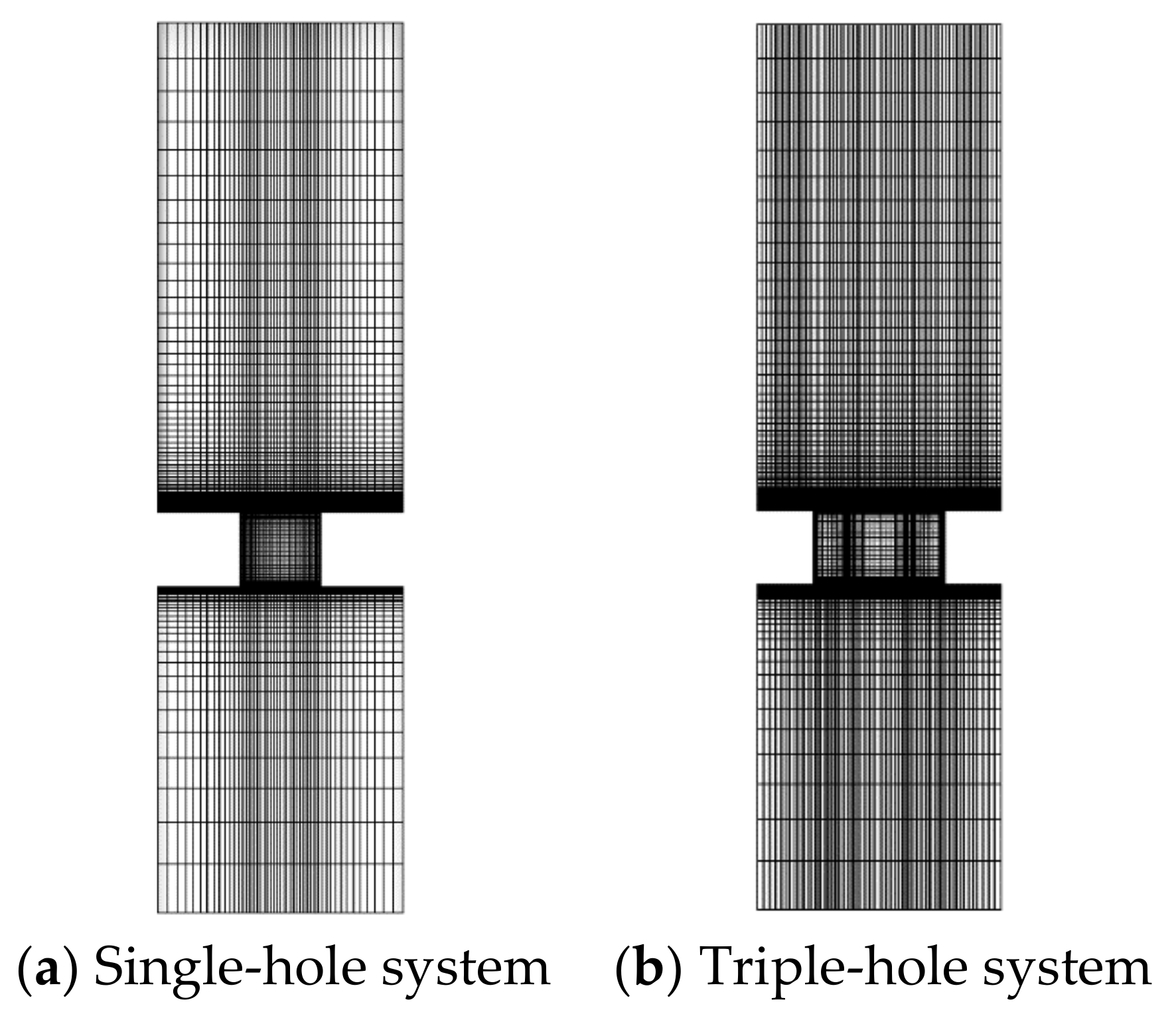
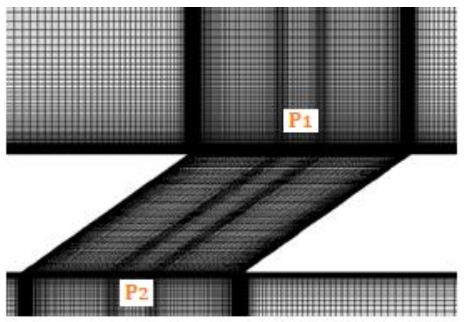
3. Numerical Methods

Numerical solutions were obtained by using ANSYS Fluent v.19 [3,24]. The CFD meshes were created in Pointwise v.18 [3,25]. CFD simulations were performed in the LES, Smagorinsky–Lilly model. The LES approach helps resolve large-scale eddies in turbulent flow and facilitates the modeling of small-scale eddies with length scales smaller than the grid spacing. The time step was 6.25 × 10⁻⁶ s, implying that the main flow convected the diameter of the single hole after 400 time steps [26,27]. In each time step, approximately 10 sub-iterations were executed to obtain well-resolved data [28]. The fluid was assumed as Newtonian and incompressible. The mainstream velocity was 10 m/s and the mean injectant velocity was 5 m/s, showing that both velocities were far below Mach = 0.3 [3,29]. The governing equations were as shown in [24]:
ρ t +   x i ρ u ¯ i = 0
ρ u ¯ t + x j ρ u ¯ i u ¯ j = x j μ u ¯ i x j + u j x i 2 3 μ u ¯ l x l δ i j d p ¯ d x i + τ i j x j
Here, τij, which denotes the subgrid scale turbulent stress, required modeling by using the Boussinesq hypothesis, similar to RANS turbulence models, as follows:
τ i j   1 3 τ k k δ i j =   μ t u ¯ i x j + u ¯ j x i  
where μt represents the turbulent viscosity.
Figure 3 and Figure 4 illustrate the meshes in the xy and yz planes, respectively [3]. The computational domains of the single-hole and triple-hole systems were composed of 2.04 and 2.69 million hexahedron cells, respectively [3]. Figure 5 illustrates a close-up of the mesh near hole. P2 and P1 represent the static pressures at the inlet and outlet of the hole, respectively.
In [3], grid sensitivity tests were conducted in the steady case (Sr = 0) and at the blowing ratio, M of 0.5 for the single-hole and triple-hole systems.

4. Results & Discussion

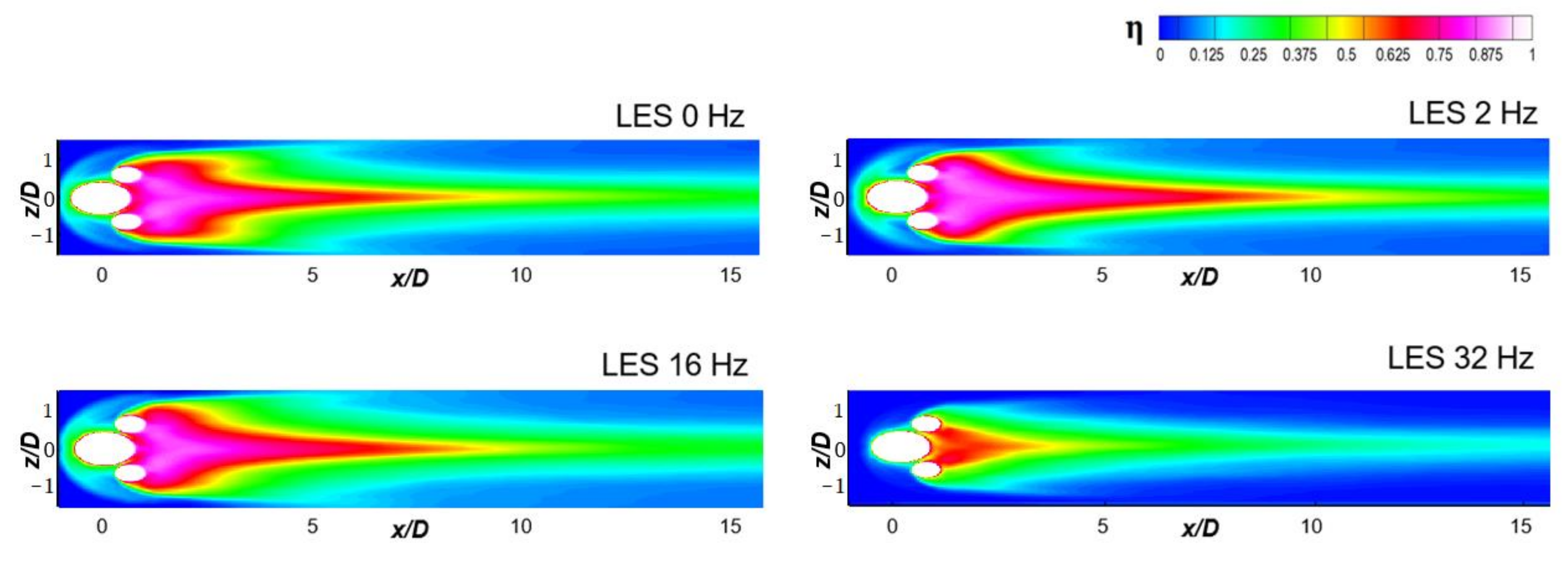
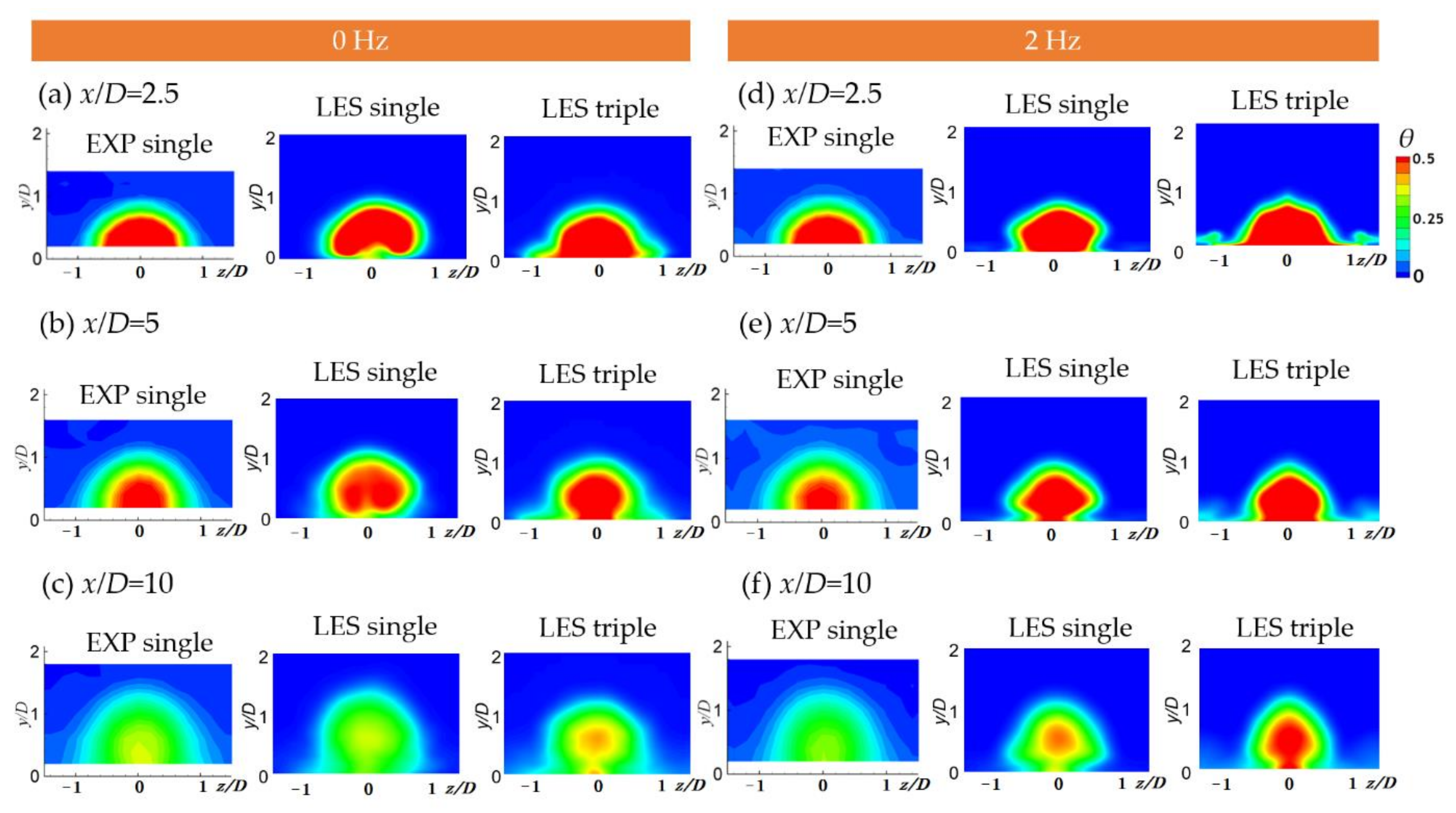
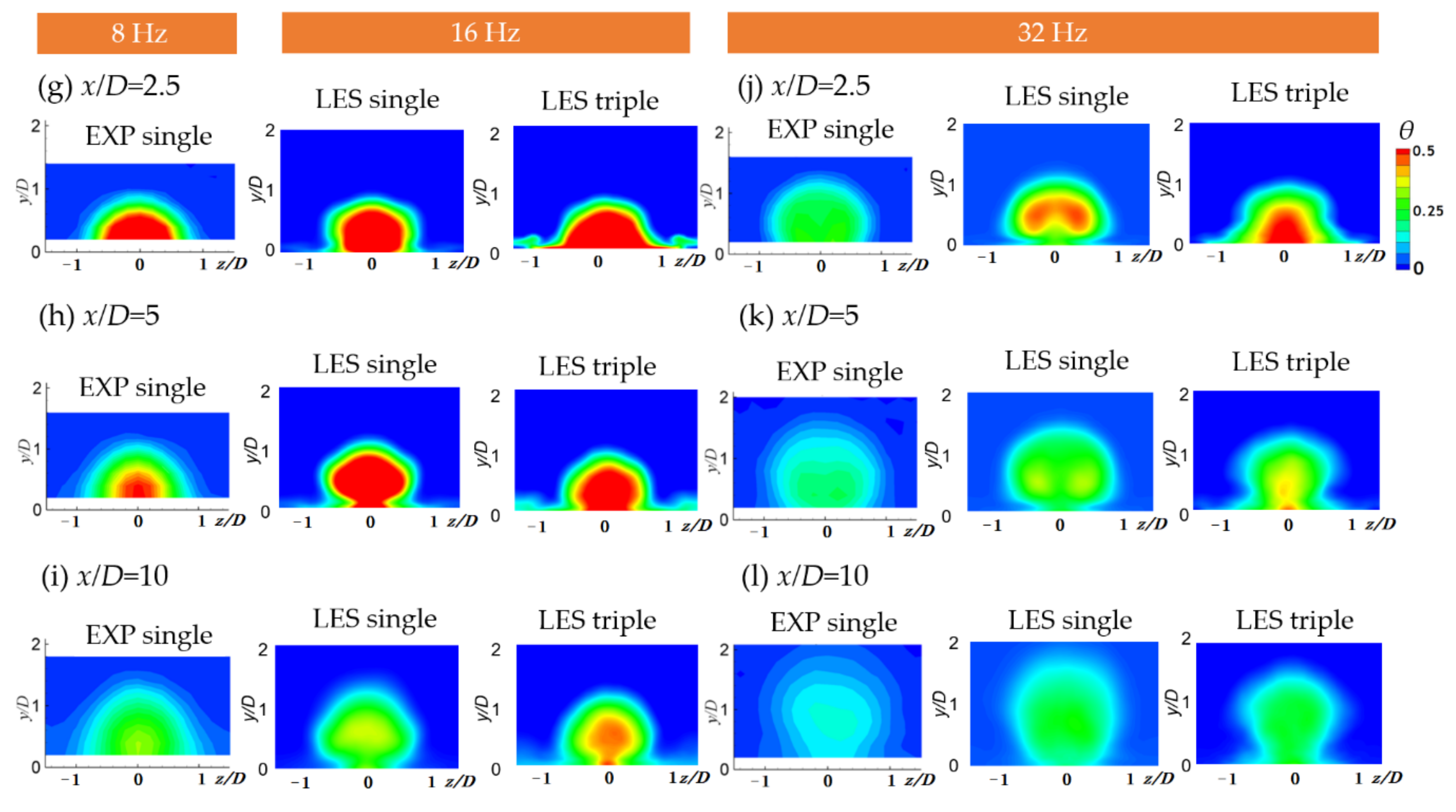
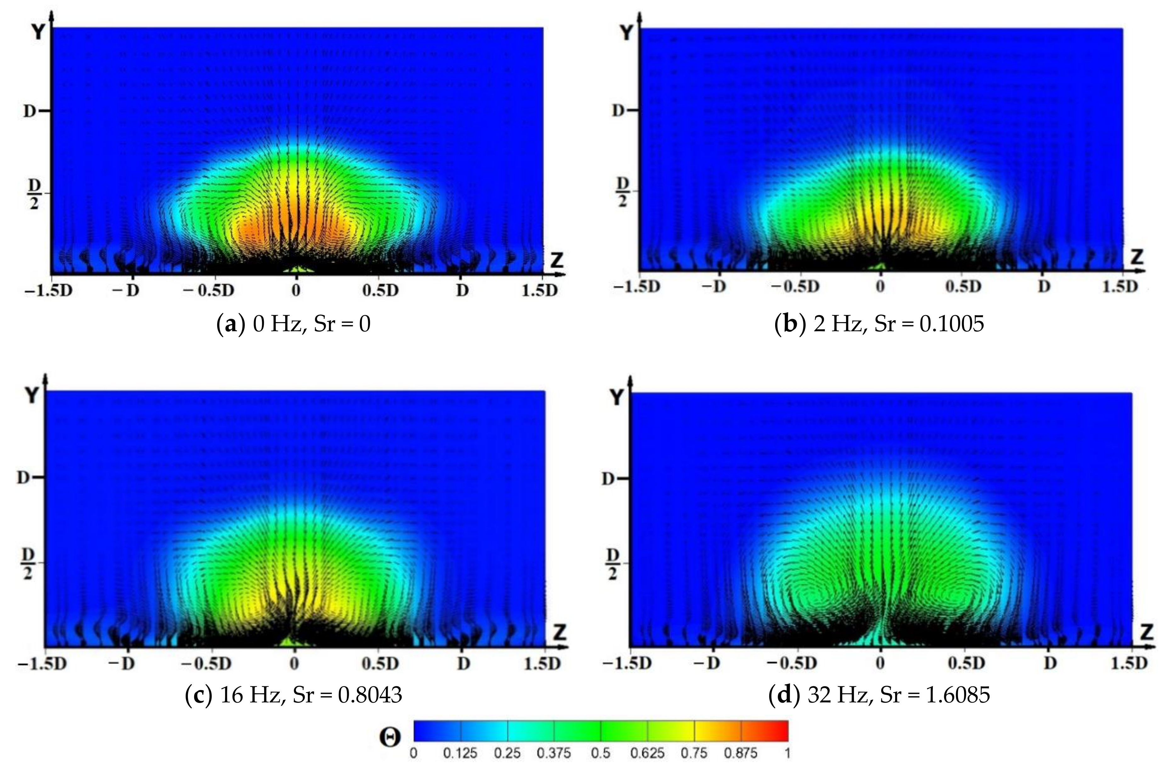
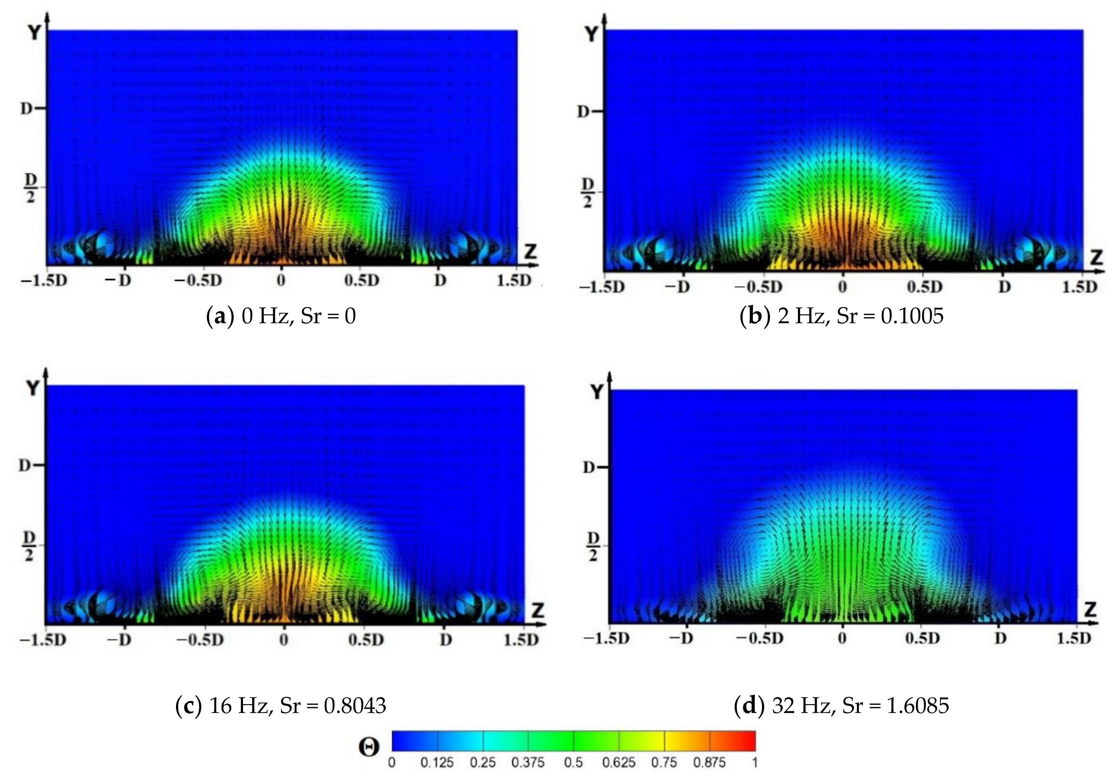
4.1. Contours of Time-Averaged η and Dimensionless Temperature

Figure 6 and Figure 7 show contours of time-averaged η on the wall for the ordinary and triple hole, respectively, at various frequencies and Strouhal numbers. The contours for the single-hole system at 0 and 32 Hz are compared to the contours with the experimental data of Jung [30]. The effectiveness is slightly over-predicted by LES, however, the contours obtained in the experiment were similar to those predicted by the LES. The coolant’s contact with the plate is hardly affected by an increase in the frequency from 0 to 16 Hz. However, it is significantly reduced by the 32 Hz pulsation owing to increased mixing. The Strouhal number for the 32 Hz pulsation is 1.6085, and as stated earlier, if the Strouhal number is greater than 1, the coolant is significantly affected by the pulsation during its passage through the hole. For each frequency of the pulsation, coolant spreading and contact with the test plate is considerably better in the triple-hole system compared with the ordinary hole system, as shown in Figure 6 and Figure 7. The improvement is attributable to the anti-CRVPs generated by the sister holes, leading to weak main CRVP and weak entrainment of hot gas under the injectant.
Figure 8 illustrates the cross-sectional dimensionless mean temperature contours at x/D = 2.5, 5, and 10 for 0 and 32 Hz pulsations and a comparison of the contours with the experimental data of Jung [30]. If there is 32 Hz pulsation in the flow, a smaller injectant comes in contact with the wall compared with at the case of 0 Hz. However, as shown in the mean effectiveness contours of the film cooling on the wall in Figure 6 and Figure 7, the coolant spreading and contact with the test plate is considerably better in the triple-hole compared with the single-hole system.
As shown in the contours of the experimental data in Figure 8, there is no data for the dimensionless temperature near the test plate because it could not be measured through cold-wire measurement. However, except near the test plate, the contours obtained in the experiment were similar to those predicted by the LES. The small difference between the LES results and the experimental data is because the experimental data were measured using an apparatus with a single hole with L/D = 4 while the LES results were obtained with a single hole with L/D = 1.6. The dimensionless temperature near the plate decreased as the mainstream flow travelled downstream, and x/D increased because of the intense mixing of the mainstream flow and coolant jet by the turbulence. Thus, at x/D = 10, the temperatures near the wall in the triple hole configuration and the single cooling hole configuration becomes similar because of the strong mixing. Figure 9 and Figure 10 show the contours for the time-averaged dimensionless temperature at x/D = 2 for the single-hole and triple-hole systems for 0, 2, 16, and 32 Hz pulsations. The anti-Counter Rotating Vortex Pairs weakened the main Counter Rotating Vortex Pair and reduced the lift off of the coolant jet, decreasing the entrainment of the hot gas of main flow under the injectant [3]. Therefore, the temperature near the test plate remained similar to the temperature of the coolant-core part and the film cooling effectiveness increased. Figure 9 and Figure 10 display cross-sectional contours of the mean dimensionless temperature and the mean velocity vectors at x/D = 2 for the single-hole and triple-hole systems, respectively. As shown in Figure 10d, the entrainment of the hot gas of the main flow under the injectant in the triple cooling hole at 32 Hz was weaker than the entrainment in the single hole at 32 Hz in Figure 9d. The mean velocity vectors were superimposed on the cross-sectional views of mean contours of the temperature at x/D = 2. In the triple cooling hole, the velocity vectors going upward were less concentrated at z = 0 compared with the single cooling hole, and the liftoff of the injectant was weakened by the generation of anti-CRVPs.

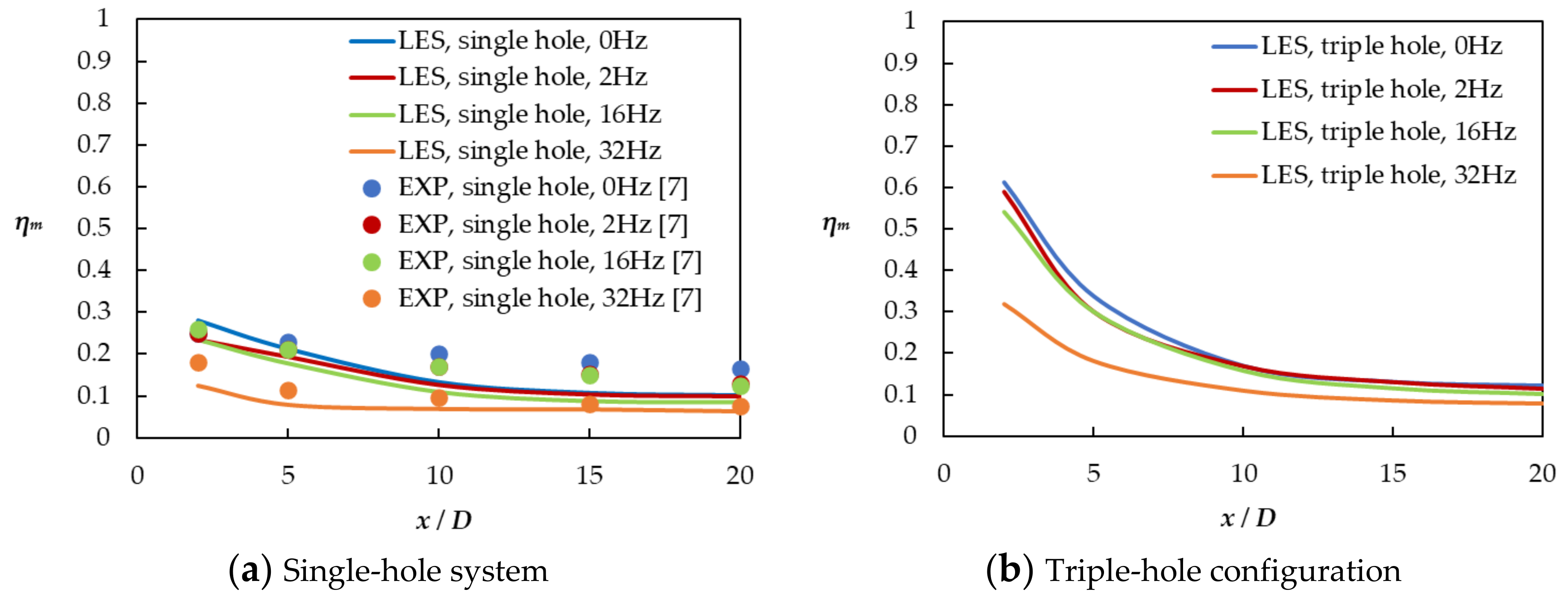
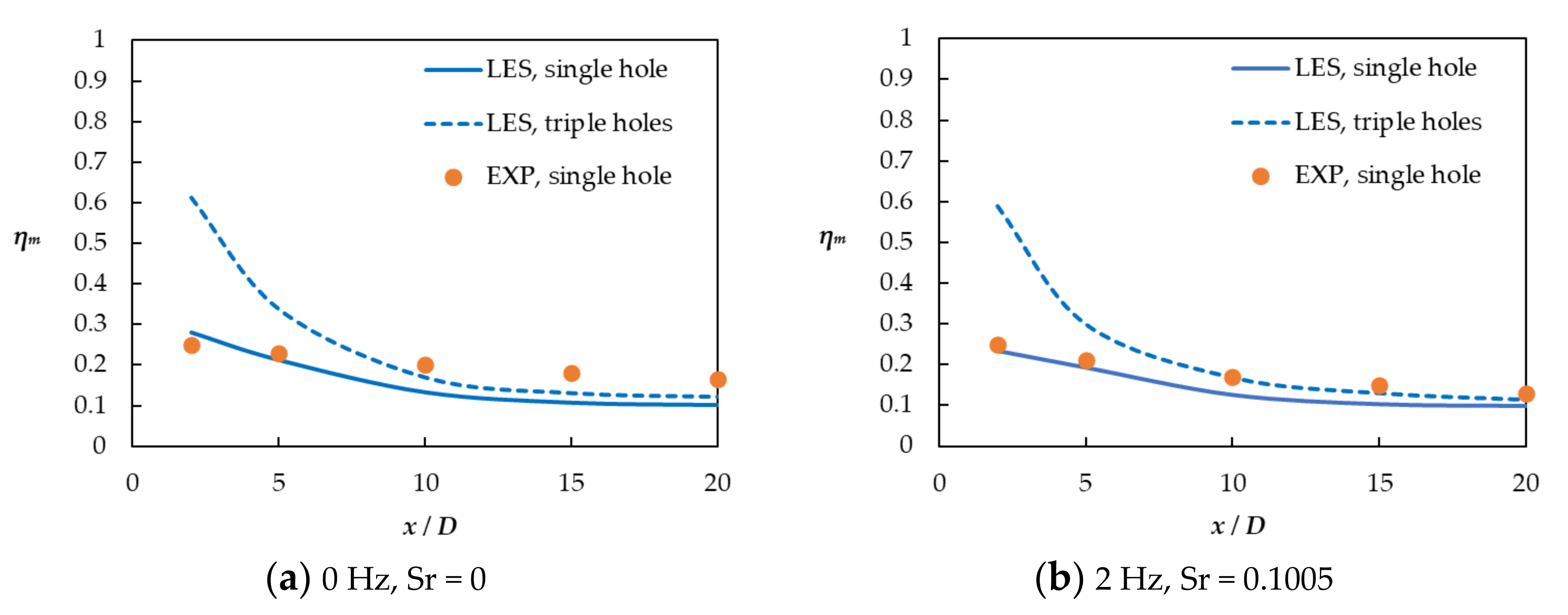
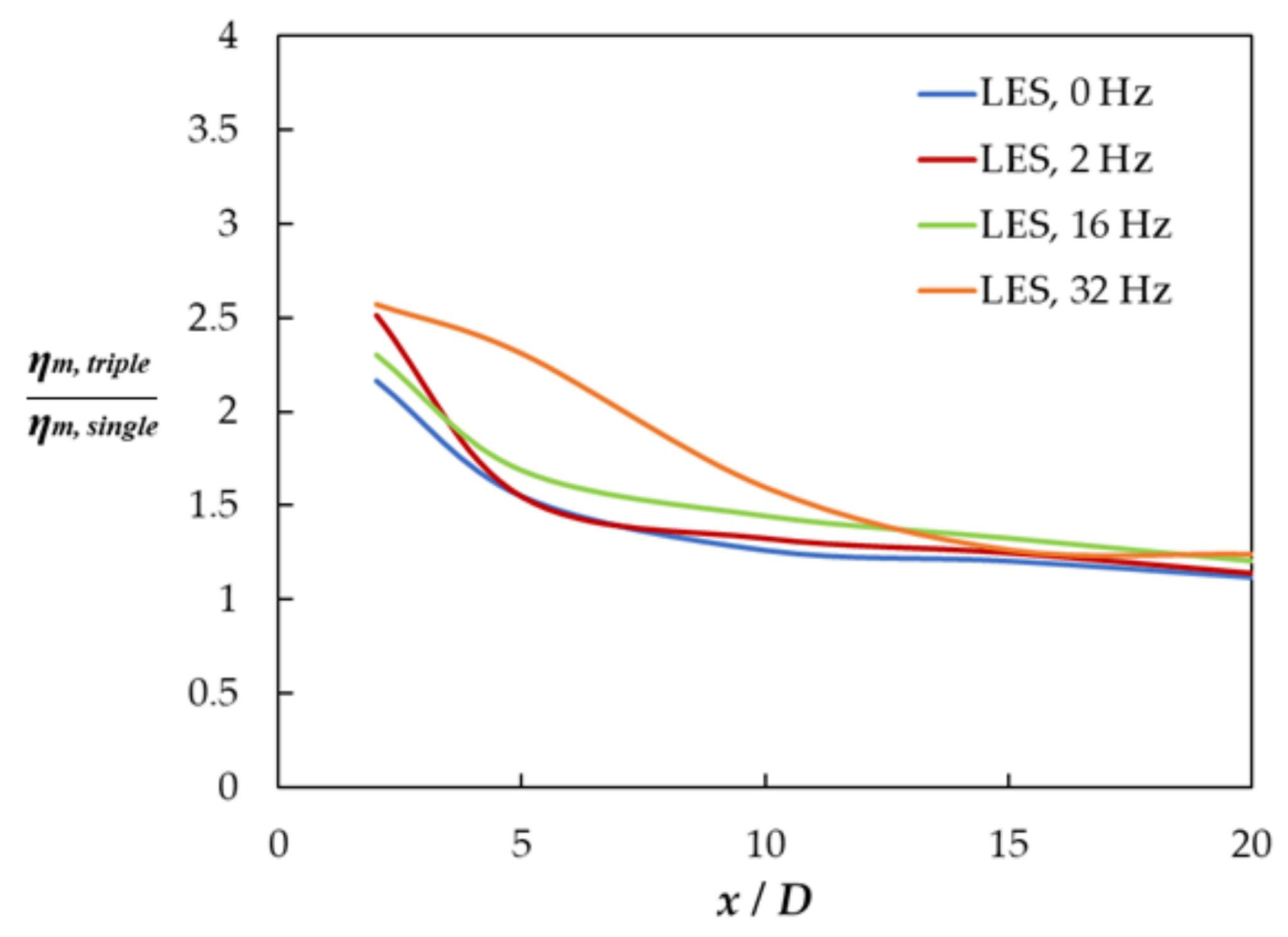
4.2. Time-Averaged Effectiveness

When the mainstream flow and injectant oscillated in the single and triple-hole configuration, the spanwise-averaged effectiveness showed identical trends. As shown in Figure 11, increasing the flow frequency reduced ηm. For the single hole, when the frequency was increased from 0 to 2, 16, and 32 Hz and the Strouhal number (Sr) from 0 to 0.1005, 0.8043, and 1.6085, the spanwise-averaged film cooling effectiveness decreased by approximately 11%, 12%, and 45%, respectively. For the triple-hole system, identical increases in the frequency and Strouhal number decreased the spanwise-averaged effectiveness by approximately 4%, 5%, and 39%, respectively. When the frequency was increased from 16 to 32 Hz, the sharp decrease in ηm was because when the Strouhal number is greater than 1, the trajectory of the injectant is considerably different from that in the steady state and the B value in Equation (2) at 32 Hz sharply increases compared with that at 2 and 16 Hz. Nevertheless, the triple-hole system showed higher effectiveness than the single-hole system, regardless of the frequency and Strouhal number, as shown in Figure 12. Experimental data [9] were available only for the single-hole system, and ηm obtained by the LES matched well with the experimental data, even though the LES results were slightly underestimated. Figure 13 depicts the ratios of ηm in the triple-hole configuration to ηm in the single-hole, for various Strouhal numbers; the ratios were obtained through LES analyses.
Increasing the pulsation frequency and Strouhal number increased the ratio of the spanwise-averaged effectiveness. While the increase was small between 0 Hz (Sr = 0) and 16 Hz (Sr = 0.8043), it was sharp from 16 Hz (Sr = 0.8043) to 32 Hz (Sr = 1.6085). This indicated that under unsteady main flows and higher pulsation frequencies and Strouhal numbers, configuring a primary hole and two small holes is better than configuring a single hole for film cooling. The coolant injection generated large disturbances in the main flow at 32 Hz because under these conditions, the amplitude of the cooling air velocity pulsation increased remarkably at the inlet of the plenum, as evident in Table 3, and a high jet liftoff was generated as mentioned earlier. Anti-CRVPs reduce the intensity of the main CRVP more effectively when high disturbances are generated in the main flow. Additionally, the ratio of the spanwise-averaged effectiveness was almost independent of the Strouhal number at x/D > 13 because the disturbances induced by the coolant jet pulsation weakened in this x/D range, reducing the film cooling effectiveness of the anti-CRVPs.

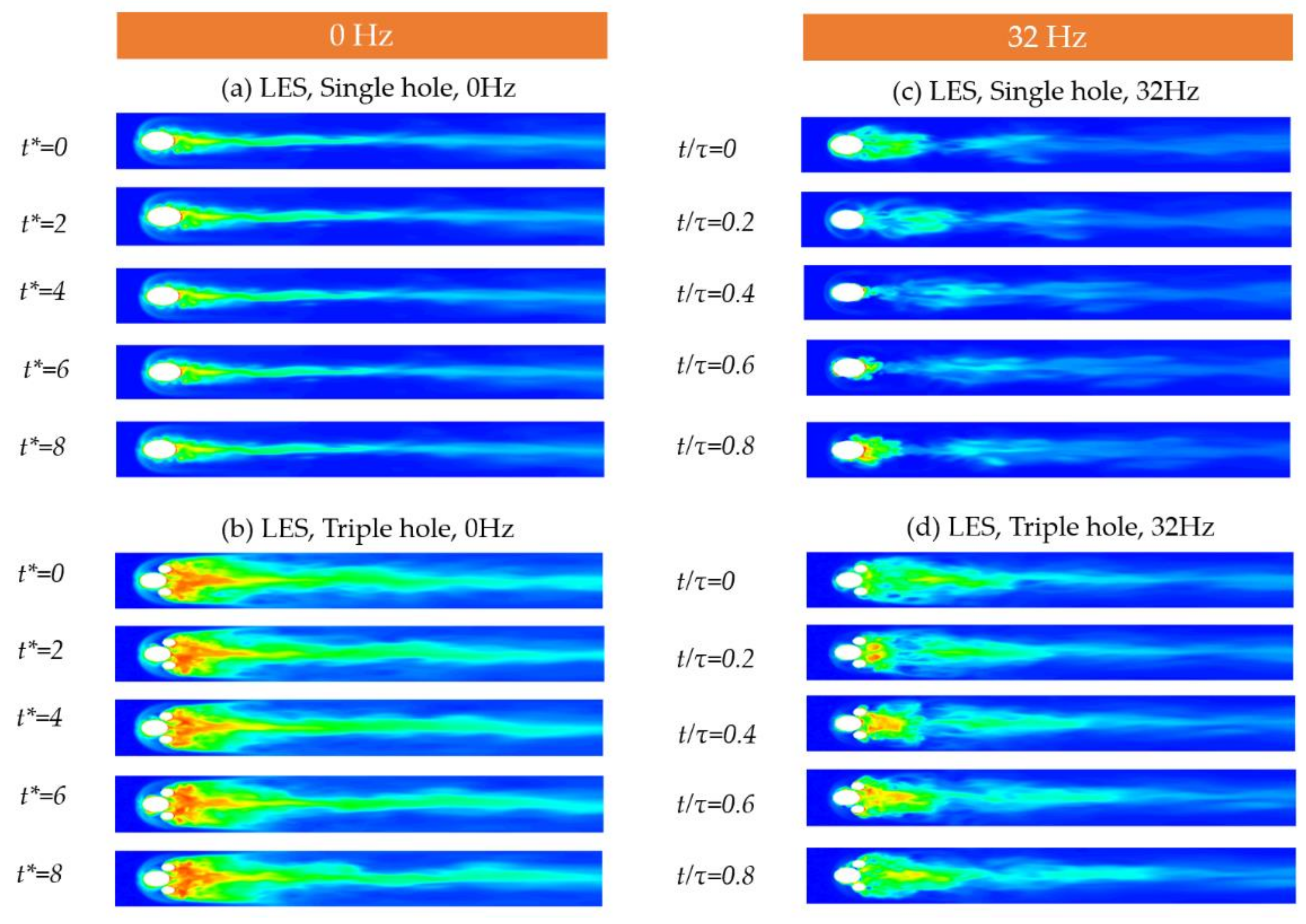
4.3. Instantaneous Effectiveness Contours on the Wall

Figure 14 shows contours of instantaneous film cooling effectiveness on the test plate obtained through LES at 0 and 32 Hz. The variable t* in Figure 14a,b represents the dimensionless time defined by the mainstream flow velocity and hole diameter, and it indicates t* = 1 as the time required for the main flow to travel across the hole diameter. Figure 14a shows LES contours of instantaneous η for the single-hole configuration under steady conditions at t* = 2, 4, 6, 8, and 10, and each contour does not show a big difference. Figure 14c,d shows the LES-derived instantaneous effectiveness of the film cooling on the test plate for each phase with 32 Hz flow pulsation. The figures show the periodic formation of a coolant covering on the plate when the coolant injection velocity varies periodically. When the frequency of the mainstream and coolant jet was increased, higher jet liftoff was generated, leading to the coolant periodically touching the test plate; the coolant could not cover the test plate efficiently as it did for 0 Hz. However, the contours for the triple-hole system showed a wider coolant spread in the spanwise direction than those for the single hole. Furthermore, the coolant covered the test plate much better through the generation of anti-CRVPs. The horseshoe vortex is shown in all contours for 0 Hz in Figure 14a,b, whereas the vortex is visible in the contours periodically at 32 Hz pulsation in Figure 14c,d. The horseshoe vortex is formed when the vortices generated in the boundary layer of the main flow are blocked by coolant injection and roll-up [31,32]. Therefore, for 32 Hz pulsation, when the injectant velocity is high magnitude velocity part of the cycle, the vortices in the boundary layer of the main flow are blocked by the injection of the coolant, resulting in a horseshoe vortex being generated as can be seen at t/τ=0.2 in Figure 14c,d. If the injectant velocity is low, the horseshoe vortex is not generated easily, and it is not clearly visible on the contour.

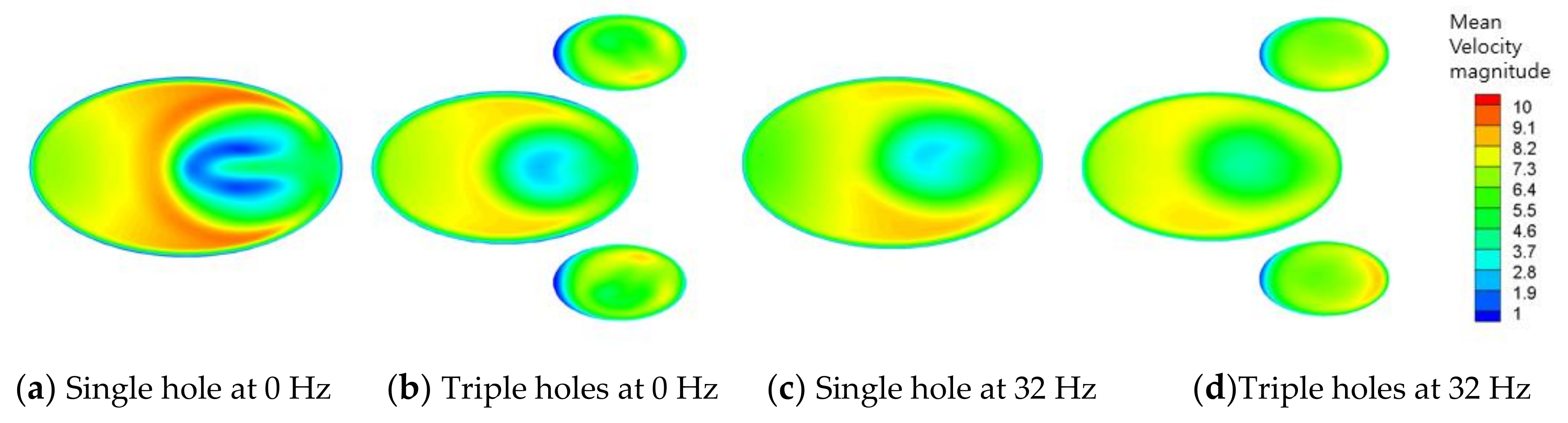
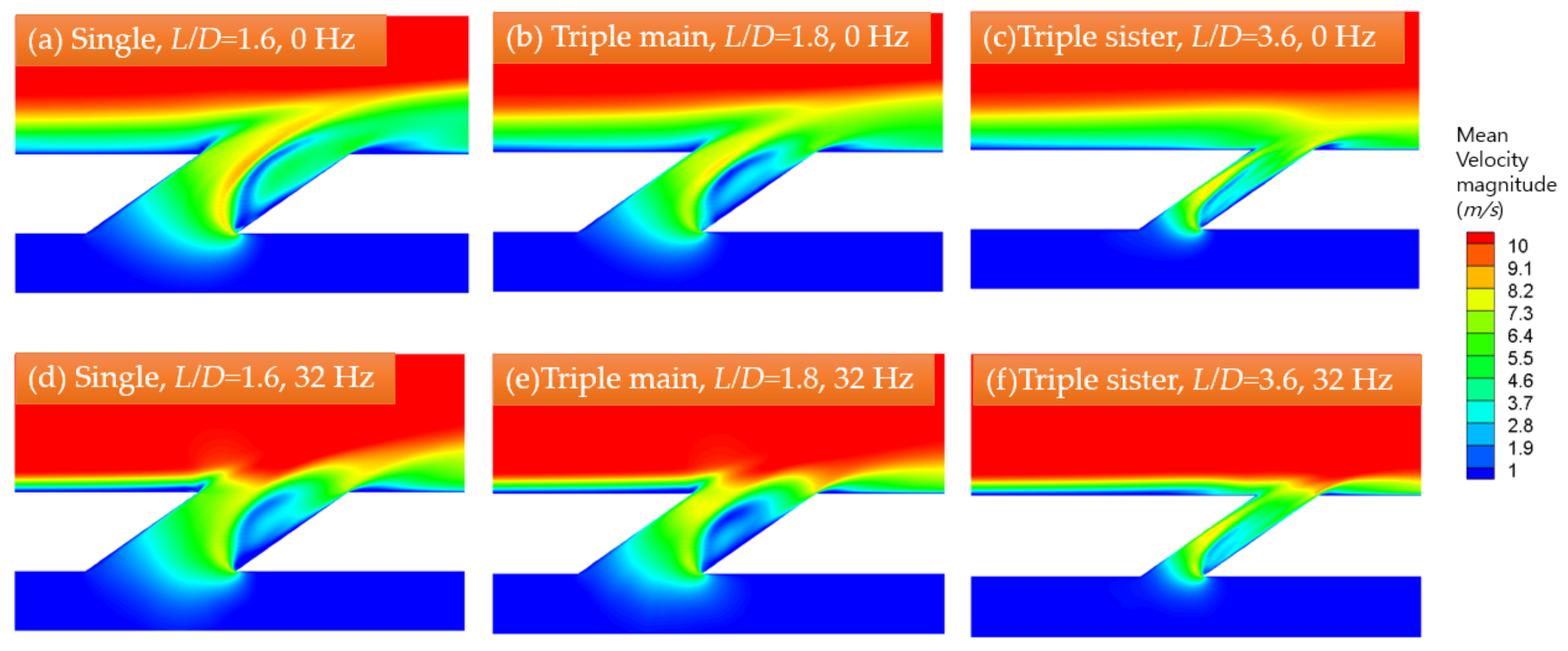
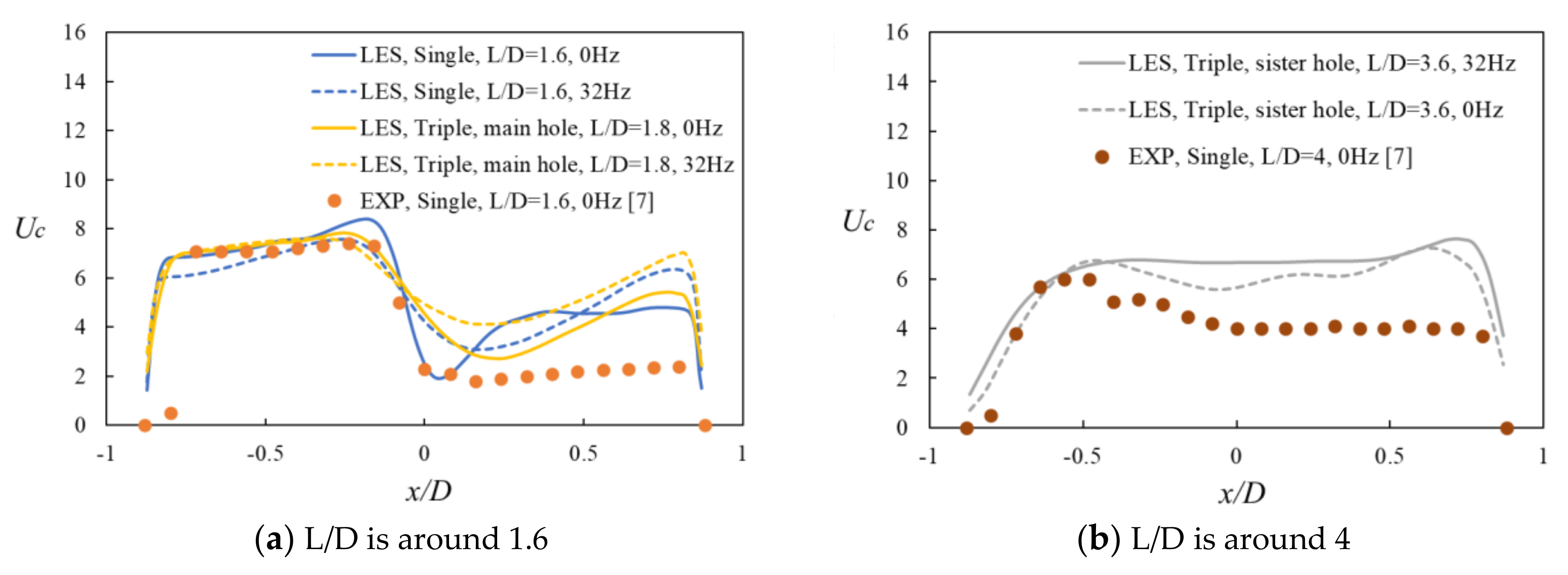
4.4. Time-averaged Velocity Magnitude in the Hole

Figure 15 illustrates time-averaged velocity magnitude contours at the hole exit for 0 and 32 Hz, obtained by an LES, and Figure 16 depicts contours of the time-averaged velocity magnitude in the hole in the z = 0 plane. The ratio of L to D in the single-hole configuration was set as 1.6, and the ratios of L to D for the primary and sister hole in the triple hole were 1.8 and 3.6, respectively. Therefore, in the triple hole, the mean velocity magnitude at the main hole exit shows distinct high and low momentum regions because of the small L/D value, while that at the sister hole exit indicates a more developed and uniform flow velocity [3]. The cooling jet with more uniform velocity is better for η due to less injectant lift off. Therefore, small hole in the triple-hole system improve η through the generation of an anti-CRVP and by increasing the L/D ratios. The same concept holds for 32 Hz pulsation. When the flow oscillates at 32 Hz, the contours of time-averaged velocity magnitude at the hole exit of the single-hole system show more uniform injectant velocity magnitude than those at 0 Hz since the amplitude of the coolant velocity at the hole exit varies periodically and thereby generates large disturbances and mixing. However, the contours of the mean velocity magnitude in the sister holes show flow that is more developed than that in the main hole, even at 32 Hz pulsation. Thus, the small holes increase η through the formation of anti-Counter Rotating Vortex Pair and by increasing the L/D ratios. In Figure 16d,e, the main flow can be inferred to invade into the windward side of the hole exit because when the flow oscillates at 32 Hz, the hot main flow in the hole reverses periodically, which is detrimental to the hole material.
Figure 17a,b shows profiles of the mean coolant velocity magnitude at the hole exit in the streamwise direction for L/D ratios around 1.6 and 4, respectively. As stated earlier, the mean velocity magnitude at the hole exit shows large variations for L/D values of 1.6 or 1.8, while that for L/D values of 3.6 or 4 is more uniform. Specifically, for the L/D value of 1.8, the mean velocity magnitude shows smaller variations compared with those for the L/D value of 1.6. Further, when there is 32 Hz pulsation in the flow, the mean velocity magnitude becomes more uniform than that in the steady state. The difference in the coolant velocity magnitude between the LES results and the experimental data for the leeward side of the hole (0 < x/D < 0.8) is attributed to the experimental operating conditions [9]. The experimental data were measured in the absence of the main flow.

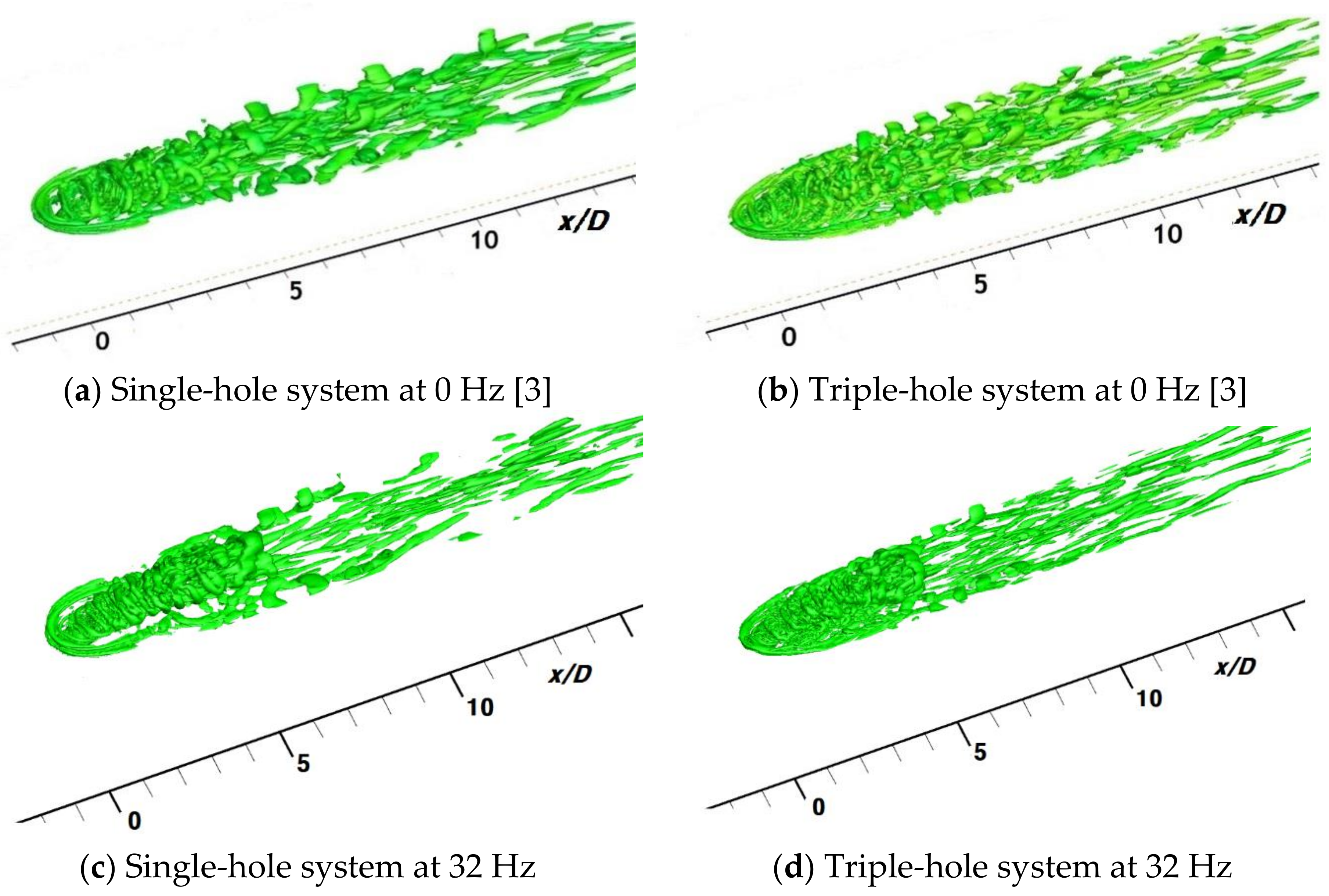
4.5. Q-Criterion Contour

Q-criterion represents the dominance of the rotation rate over the strain rate [33,34]. The instantaneous contours of the Q-criterion for the single and triple hole configurations at 0 and 32 Hz are shown in Figure 18.
The instantaneous Q-contours at 32 Hz were captured when the coolant velocity at the exit was higher than its average value, and therefore, it illustrated various vortex structures like the kidney vortex, Kelvin-Helmholtz vortices, hairpin and horseshoe vortices more clearly than at 0 Hz. However, Q-criterion contours for the triple-hole configuration at 0 and 32 Hz showed smaller hairpin and Kelvin-Helmholtz vortices than those for the single-hole configuration. These smaller hairpin vortices were related to weakened Counter Rotating Vortex Pair [35]. A weakened Counter Rotating Vortex Pair increased η on the wall.

5. Conclusions

The mainstream of film cooling can be disturbed by several factors. The specific goal of the current study is to investigate the effects of the main flow pulsation on the film cooling performance for the triple holes system in order to help for making better cooling design of the gas turbine engines. Film cooling in a triple hole system was numerically simulated in an LES. Contours of η on the wall and cross-sectional views of the mean dimensionless temperature contours for the single-hole and triple-hole systems showed that the triple-hole configuration exhibits better film cooling performance for 0, 2, 16, and 32 Hz pulsations. In the triple-hole system, increasing the frequency to 32 Hz or Strouhal number from 0 to 1.6085 decreased the film cooling effectiveness to a lesser extent compared with the single-hole system. As the frequency increased from 0 to 2, 16, and 32 Hz in the single-hole, laterally averaged η decreased by approximately 11%, 12%, and 45%, respectively, and this trend was confirmed in the experimental data. In the triple hole, increasing the frequency from 0 to 2, 16, and 32 Hz decreased the spanwise-averaged film cooling effectiveness by approximately 4%, 5%, and 39%, respectively. The film cooling effectiveness was always higher in the triple-hole system because of the generation of an anti-CRVP. Furthermore, increasing the pulsation frequency or Strouhal number increased the ratio of ηm, triple hole to ηm, single hole, indicating that at higher pulsation frequencies or Strouhal numbers in the main flow, the triple holes were more effective for film cooling compared with the single hole. Contours of time-averaged velocity magnitude in sister holes showed that the flow was more developed than that in the main hole, even at 32 Hz pulsation. This indicated that the sister holes improved the film cooling effectiveness through the generation of an anti-CRVP and by increasing the L/D ratios. Q-contours for triple hole at 0 and 32 Hz showed smaller hairpin and jet shear layer vortices compared with those for the single-hole system, indicating a weakened CRVP. In the contours of the instantaneous film cooling effectiveness, the horseshoe vortex was visible periodically at 32 Hz pulsation because this vortex was generated when the vortex in the boundary layer of the main flow was blocked by strong coolant injection and roll-up. This paper only covered the cylindrical hole, however, the effects of the main flow pulsations on film cooling for the shaped hole such as the forward expansion hole will be covered in future studies. Moreover, the effects for the two sister holes positioned more downstream of the primary hole and the optimized length between the sister hole and the primary hole will be investigated to obtain the best film cooling performance. For the parametric study, the CFD results of this study could be used as the baseline.

Author Contributions

Simulations, S.I.B.; analysis, S.I.B. and J.A.; writing, S.I.B. and J.A.; supervision, J.A. All authors have read and agreed to the published version of the manuscript.

Funding

No external funding.

Institutional Review Board Statement

Not applicable.

Informed Consent Statement

Not applicable.

Data Availability Statement

Data is contained within this article.

Conflicts of Interest

No conflict of interest.

Nomenclature

Ddiameter of single hole
Lhole length
Mblowing ratio = ρ C U C / ρ G U G
SrStrouhal number = 2 π f L U G
Uflow velocity
Greek symbols
η film cooling effectiveness
η C effectiveness at the centerline
η m laterally-averaged effectiveness
Θdimensionless temperature =   T G T T G   T C

References

  1. Moran, M.; Shapiro, H.; Boettner, D.; Bailey, M. Fundamentals of Engineering Thermodynamics, 8th ed.; John Wiley & Sons: Hoboken, NJ, USA, 2014; p. 532. [Google Scholar]
  2. Baek, S.I.; Yavuzkurt, S. Effects of Flow Oscillations in the Mainstream on Film Cooling. Inventions 2018, 3, 73. [Google Scholar] [CrossRef] [Green Version]
  3. Baek, S.I.; Ahn, J. Large Eddy Simulation of Film Cooling with Triple Holes: Injectant Behavior and Adiabatic Film-Cooling Effectiveness. Processes 2020, 8, 1443. [Google Scholar] [CrossRef]
  4. Heidmann, J.; Ekkad, S. A novel anti-vortex turbine film cooling hole concept. In Proceedings of the ASME Turbo Expo 2007, GT2007-27528, Montreal, QC, Canada, 14–17 May 2007. [Google Scholar] [CrossRef]
  5. Javadi, K.; Taeibi-Rahni, M.; Darbandi, M.; Javadi, K. Jet-into-Crossflow Boundary-Layer Control: Innovation in Gas Turbine Blade Cooling. AIAA J. 2007, 45, 2910–2925. [Google Scholar] [CrossRef]
  6. Ely, M.J.; Jubran, B.A. A numerical evaluation on the effect of sister holes on film cooling effectiveness and the surrounding flow field. Heat Mass Transf. 2009, 45, 1435–1446. [Google Scholar] [CrossRef]
  7. Choi, D.-W.; Lee, K.-D.; Kim, K.-Y. Analysis and Optimization of Double-Jet Film-Cooling Holes. J. Thermophys. Heat Transf. 2013, 27, 246–254. [Google Scholar] [CrossRef]
  8. Wu, H.; Cheng, H.; Li, Y.; Rong, C.; Ding, S. Effects of side hole position and blowing ratio on sister hole film cooling performance in a flat plate. Appl. Therm. Eng. 2016, 93, 718–730. [Google Scholar] [CrossRef]
  9. Seo, H.; Leea, J.; Ligrani, P. The effect of injection hole length on film cooling with bulk flow pulsations. Int. J. Heat Mass Transf. 1998, 41, 3515–3528. [Google Scholar] [CrossRef]
  10. Kim, S.I.; Hassan, I. Unsteady Simulations of a Film Cooling Flow from an Inclined Cylindrical Jet. J. Thermophys. Heat Transf. 2010, 24, 145–156. [Google Scholar] [CrossRef]
  11. Gau, C.; Yih, K.A.; Chang, S. Swirling flow effect on film cooling performance downstream of a sudden expansion. J. Thermophys. Heat Transf. 1991, 5, 89–95. [Google Scholar] [CrossRef]
  12. Coulthard, S.M.; Volino, R.J.; Flack, K.A. Effect of Jet Pulsing on Film Cooling—Part I: Effectiveness and Flow-Field Temperature Results. J. Turbomach. 2006, 129, 232–246. [Google Scholar] [CrossRef]
  13. Nikitopoulos, D.E.; Acharya, S.; Oertling, J.; Muldoon, F.H. On Active Control of Film-Cooling Flows. In Proceedings of the ASME Turbo Expo, GT2006-90051, Barcelona, Spain, 8–11 May 2006. [Google Scholar] [CrossRef]
  14. Ekkad, S.V.; Ou, S.; Rivir, R.B. Effect of Jet Pulsation and Duty Cycle on Film Cooling from a Single Jet on a Leading Edge Model. J. Turbomach. 2006, 128, 564–571. [Google Scholar] [CrossRef]
  15. Gao, Z.; Narzary, D.P.; Mhetras, S.; Han, J. Upstream Vortex Effects on Turbine Blade Platform Film Cooling with Typical Purge Flow. J. Thermophys. Heat Transf. 2012, 26, 75–84. [Google Scholar] [CrossRef]
  16. Xiao, B.; Wang, W.; Zhang, X.; Long, G.; Fan, J.; Chen, H.; Deng, L. A novel fractal solution for permeability and Kozeny-Carman constant of fibrous porous media made up of solid particles and porous fibers. Powder Technol. 2019, 349, 92–98. [Google Scholar] [CrossRef]
  17. Liang, M.; Fu, C.; Xiao, B.; Luo, L.; Wang, Z. A fractal study for the effective electrolyte diffusion through charged porous media. Int. J. Heat Mass Transf. 2019, 137, 365–371. [Google Scholar] [CrossRef]
  18. Farhadi-Azar, R.; Ramezanizadeh, M.; Taeibi-Rahni, M.; Salimi, M. Compound Triple Jets Film Cooling Improvements via Velocity and Density Ratios: Large Eddy Simulation. J. Fluids Eng. 2011, 133, 031202. [Google Scholar] [CrossRef]
  19. Johnson, P.L.; Kapat, J.S. Large-Eddy Simulations of a Cylindrical Film Cooling Hole. J. Thermophys. Heat Transf. 2013, 27, 255–273. [Google Scholar] [CrossRef]
  20. Baldauf, S.; Scheurlen, M.; Schulz, A.; Wittig, S. Correlation of Film-Cooling Effectiveness from Thermographic Measurements at Enginelike Conditions. J. Turbomach. 2002, 124, 686–698. [Google Scholar] [CrossRef]
  21. Babaee, H.; Wan, X.; Acharya, S. Effect of Uncertainty in Blowing Ratio on Film Cooling Effectiveness. J. Heat Transf. 2013, 136, 031701. [Google Scholar] [CrossRef]
  22. Bogard, D. Airfoil Film Cooling. In The Gas Turbine Handbook; National Energy Technology Laboratory: Albany, NY, USA, 2006. [Google Scholar]
  23. Seo, H. Film Cooling Flow and Heat Transfer Characteristics with the Strouhal Number Variations in Pulsating Flows. Ph.D. Thesis, Seoul National University, Seoul, Korea, 1997. [Google Scholar]
  24. ANSYS Fluent Theory Guide. Version 19. Available online: https://www.ansys.com/products/fluids/ansys-fluent (accessed on 10 December 2020).
  25. Pointwise Version 18. Available online: http://www.pointwise.com/ (accessed on 10 December 2020).
  26. Renze, P.C.-A.; Schröder, W.; Meinke, M. Large-eddy Simulation of Film Cooling Flows with Variable Density Jets. Flow Turbul. Combust. 2007, 80, 119–132. [Google Scholar] [CrossRef]
  27. Iourokina, I.; Lele, S. Towards large eddy simulation of film cooling flows on a model turbine blade leading edge. In Proceedings of the 43rd AIAA Aerospace Sciences Meeting and Exhibit, No. 2005-0670, Reno, NV, USA, 10–13 January 2005. [Google Scholar]
  28. Acharya, S.; Leedom, D.H. Large Eddy Simulations of Discrete Hole Film Cooling with Plenum Inflow Orientation Effects. J. Heat Transf. 2012, 135, 011010. [Google Scholar] [CrossRef]
  29. White, F. Fluid Mechanics, 4th ed.; McGraw-Hill: New York, NY, USA, 1999. [Google Scholar]
  30. Jung, I.S.; Lee, J.S. Effects of Orientation Angles on Film Cooling Over a Flat Plate: Boundary Layer Temperature Distributions and Adiabatic Film Cooling Effectiveness. J. Turbomach. 1999, 122, 153–160. [Google Scholar] [CrossRef]
  31. Fric, T.F.; Roshko, A. Vortical structure in the wake of a transverse jet. J. Fluid Mech. 1994, 279, 1–47. [Google Scholar] [CrossRef] [Green Version]
  32. Shyam, V.; Thurman, D.; Poinsatte, P.; Ameri, A.A.; Eichele, P. Long Hole Film Cooling Dataset for CFD Development—Flow and Film Effectiveness. In Proceedings of the 50th AIAA/ASME/SAE/ASEE Joint Propulsion Conference, Cleveland, OH, USA, 28–30 July 2014; American Institute of Aeronautics and Astronautics (AIAA): Reston, VA, USA, 2014. [Google Scholar]
  33. Kolář, V. Vortex identification: New requirements and limitations. Int. J. Heat Fluid Flow 2007, 28, 638–652. [Google Scholar] [CrossRef]
  34. Schroder, A.; Willert, C. Particle Image Velocimetry: New Developments and Recent Applications; Springer: Berlin/Heidelberg, Germany, 2008; p. 382. [Google Scholar]
  35. Yao, Y.; Zhang, J.; Yang, Y. Numerical study on film cooling mechanism and characteristics of cylindrical holes with branched jet injections. Propuls. Power Res. 2013, 2, 30–37. [Google Scholar] [CrossRef] [Green Version]
Figure 1. Computational domains.
Applsci 11 01537 g001
Figure 2. Schematics of hole systems [3].
Applsci 11 01537 g002
Figure 3. Computational fluid dynamics grids in the xy plane [3].
Applsci 11 01537 g003
Figure 4. Grids in the yz plane [21].
Applsci 11 01537 g004
Figure 5. Close-up view of the grid near the injection region [3].
Applsci 11 01537 g005
Figure 6. Contours of time-averaged η on the wall for single-hole system for 0 (Sr = 0), 2 (Sr = 0.1005), 16 (Sr = 0.8043) and 32 Hz (Sr = 1.6085).
Applsci 11 01537 g006
Figure 7. Contours of time-averaged η on the wall for the triple hole for 0 (Sr = 0), 2 (Sr = 0.1005), 16 (Sr = 0.8043) and 32 Hz (Sr = 1.6085).
Applsci 11 01537 g007
Figure 8. Cross-sectional time-averaged dimensionless temperature distributions at M = 0.5.
Applsci 11 01537 g008aApplsci 11 01537 g008b
Figure 9. Contours of time-averaged dimensionless temperature and velocity vectors at x/D = 2 for the single cooling hole system: (a) 0 Hz, Sr = 0; (b) 2 Hz, Sr = 0.1005; (c) 16 Hz, Sr = 0.8043; and (d) 32 Hz, Sr = 1.6085.
Applsci 11 01537 g009
Figure 10. Contours of time-averaged dimensionless temperature and velocity vectors at x/D = 2 for the triple-hole system (a) 0 Hz, Sr = 0; (b) 2 Hz, Sr = 0.1005; (c) 16 Hz, Sr = 0.8043; and (d) 32 Hz, Sr = 1.6085.
Applsci 11 01537 g010
Figure 11. ηm under unsteady conditions.
Applsci 11 01537 g011
Figure 12. Laterally-averaged effectiveness under unsteady conditions: (a) 0 Hz, Sr = 0; (b) 2 Hz, Sr = 0.1005; (c) 16 Hz, Sr = 0.8043; and (d) 32 Hz, Sr = 1.6085.
Applsci 11 01537 g012aApplsci 11 01537 g012b
Figure 13. Ratios of ηm,triple to ηm,single at 0 Hz (Sr = 0), 2 Hz (Sr = 0.1005), 16 Hz (Sr = 0.8043), and 32 Hz (Sr = 1.6085).
Applsci 11 01537 g013
Figure 14. Contours of instantaneous η on the wall obtained by an LES: (a) Single hole at 0 Hz, (b) triple holes at 0 Hz, (c) single hole at 32 Hz, and (d) triple holes at 32 Hz.
Applsci 11 01537 g014
Figure 15. Mean velocity magnitude at the hole exit.
Applsci 11 01537 g015
Figure 16. Contours of time-averaged velocity magnitude in the hole at the centerline.
Applsci 11 01537 g016
Figure 17. Profiles of the mean coolant velocity magnitude at the hole exit in the streamwise direction.
Applsci 11 01537 g017
Figure 18. Q-criterion contours (level: 80,000).
Applsci 11 01537 g018
Table 1. Boundary conditions.
SurfaceBoundary Condition
Main inletVelocity inlet
Plenum inletVelocity inlet
TopSymmetry
Test plateAdiabatic wall
OutflowPressure outlet
Main sidesPeriodic
Sides of plenumWall
Tube wallWall
Table 2. Pulsation amplitude A and frequency in Equation (1) at different Strouhal numbers (Sr).
Frequency (Hz)021632
Sr00.10050.80431.6085
A01.820.570.44
Table 3. Pulsation amplitude B and frequency in Equation (2) at different Strouhal numbers (Sr).
Frequency (Hz)021632
Sr00.10050.80431.6085
B00.040.050.16
Publisher’s Note: MDPI stays neutral with regard to jurisdictional claims in published maps and institutional affiliations.

