Article

Partial Threading of Pedicle Screws in a Standard Construct Increases Fatigue Life: A Biomechanical Analysis

1
Department of Surgery, Division of Neurosurgery, National Taiwan University Hospital, Taipei City 10022, Taiwan
2
Department of Orthopedics, Shuang Ho Hospital, Taipei Medical University, New Taipei City 23561, Taiwan
3
Graduate Institute of Biomedical Materials and Tissue Engineering, College of Biomedical Engineering, Taipei Medical University, Taipei City 11031, Taiwan
4
Department of Orthopedic Surgery, Taipei Municipal Wanfang Hospital, Taipei Medical University, Taipei City 116, Taiwan
5
Department of Orthopedic Surgery, School of Medicine, College of Medicine, Taipei Medical University, Taipei City 110, Taiwan
*
Author to whom correspondence should be addressed.
Appl. Sci. 2021, 11(4), 1503; https://doi.org/10.3390/app11041503
Submission received: 11 January 2021 / Revised: 3 February 2021 / Accepted: 4 February 2021 / Published: 7 February 2021

Abstract

:
This study proposed a pedicle screw design where the proximal 1/3 of the screw is unthreaded to improve fixation in posterior spinal surgery. This design was also expected to reduce the incidence of mechanical failure often observed when an unsupported screw length is exposed outside the vertebra in deformed or degenerated segments. The aim of this study was to evaluate the fatigue life of the novel pedicle screw design using finite element analysis and mechanical testing in a synthetic spinal construct in accordance with American Society for Testing and Materials (ASTM) F1717. The following setups were evaluated: (i) pedicle screw fully inserted into the test block (EXP-FT-01 and EXP-PU-01; full thread (FT), proximal unthread (PU)) and (ii) pedicle screw inserted but leaving an exposed shaft length of 7.6 mm (EXP-FT-02 and EXP-PU-02). Corresponding finite element models FEM-FT-01, FEM-FT-02, FEM-PU-01, and FEM-PU-02 were also constructed and subjected to the same loading conditions as the experimental groups. The results showed that under a 220 N axial load, the EXP-PU-01 group survived the full 5 million cycles, the EXP-PU-02 group failed at 4.4 million cycles on average, and both EXP-FT-01 and EXP-FT-02 groups failed after less than 1.0 million cycles on average, while the fatigue strength of the EXP-FT-02 group was the lowest at 170 N. The EXP-FT-01 and EXP-FT-02 constructs failed through fracture of the pedicle screw, but a rod fractured in the EXP-PU-02 group. In comparison to the FEM-FT-01 model, the maximum von Mises stress on the pedicle screw in the FEM-PU-01 and FEM-PU-02 models decreased by −43% and −27%, respectively. In conclusion, this study showed that having the proximal 1/3 of the pedicle screw unthreaded can reduce the risk of screw fatigue failure when used in deformed or degenerated segments.

1. Introduction

The primary function of pedicle screw systems is to maintain spinal stability while fusion occurs. However, in weakened or osteoporotic bone, the bone–screw interface is often poor and prone to failure, resulting in screw loosening or back-out after surgery. Transpedicular instrumentation in patients with osteoporosis is difficult because of the challenge in achieving sufficient fixation strength. In addition, biomechanical studies have shown a reduction in the pull-out strength of pedicle screws in osteoporotic bone, which can ultimately lead to failure of internal fixation [1,2,3]. As such, fixation problems are common in patients suffering from osteoporosis, and gaining sufficient pedicle screw fixation is a major challenge for spinal surgeons. Loosening of pedicle screws is a leading cause of non-union, pseudarthrosis, and back pain after surgery.
One method to improve the interface strength between pedicle screws and surrounding bone in osteoporotic patients is to use a bone-cement-augmented pedicle screw, which has been shown to increase the pull-out strength [4,5,6]. However, complications such as cement leakage outside the vertebral body and difficulty in removing the fixed screw have been reported. Symptomatic cement leakage with augmented screws has been reported at up to 17% [7,8], while Mueller et al. indicated that perivertebral cement leakage occurs in 73.3% of cases, but most are clinically asymptomatic [9]. Besides cement augmentation, changing the screw design, including diameter, length, and thread design, may be used to improve fixation [10,11,12,13]. Because the holding power of the bone–screw interface is poor in osteoporosis, increasing the diameter of the screw may improve fixation and stability [14]. However, the maximum diameter of the screw is limited by the anatomical shape of the pedicle, and so the viable size range for the screw is limited.
A previous study by the authors demonstrated that having the proximal 1/3 of the pedicle screw left unthreaded significantly improves the pull-out strength and withdrawal force in comparison to a fully threaded screw [15]. The authors considered that this novel screw design could also improve the fatigue life of the pedicle screw in cases where only partial screw insertion is required [16]. Hence, this study aimed to evaluate the fatigue life and stress distribution of proximally unthreaded screws in accordance with American Society for Testing and Materials (ASTM) F1717 [17] and using finite element analysis. The results were compared with those obtained from fully threaded pedicle screws.

2. Materials and Methods

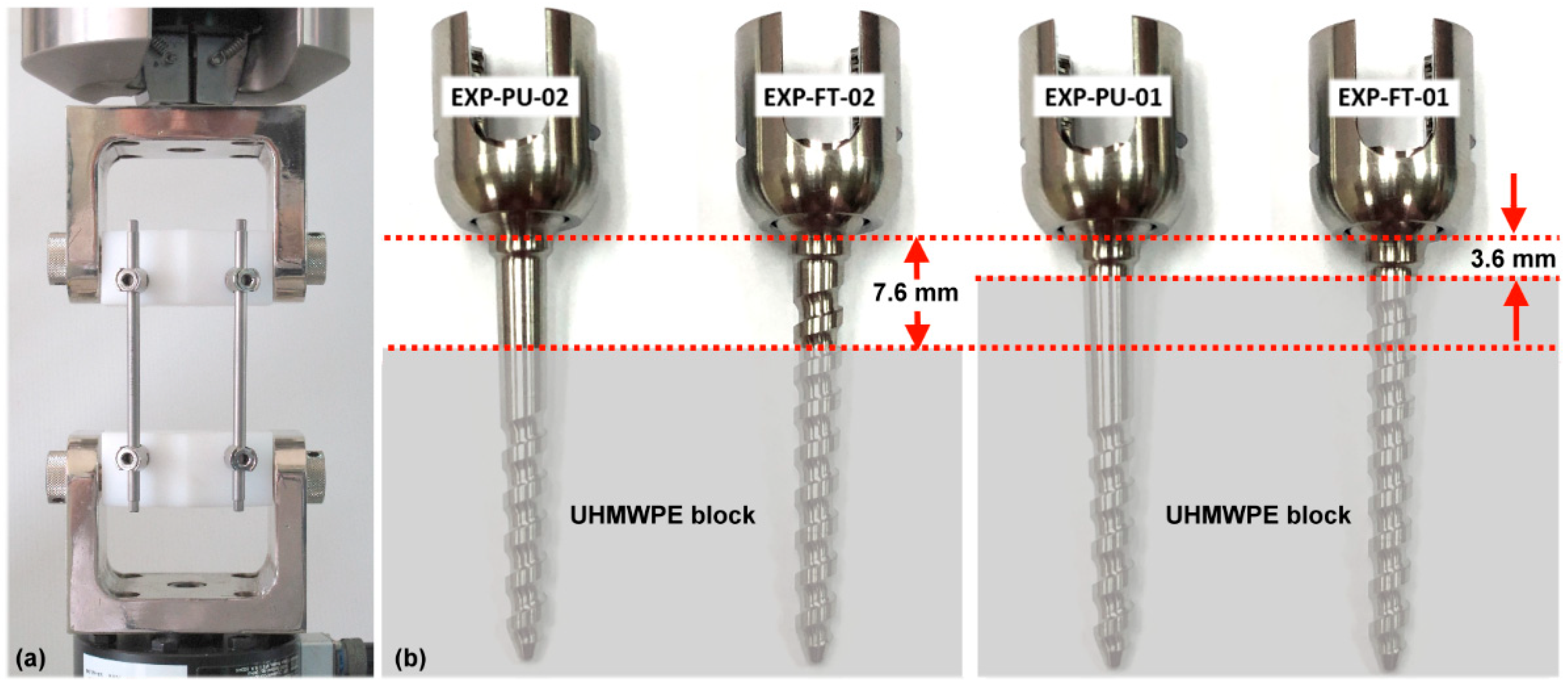
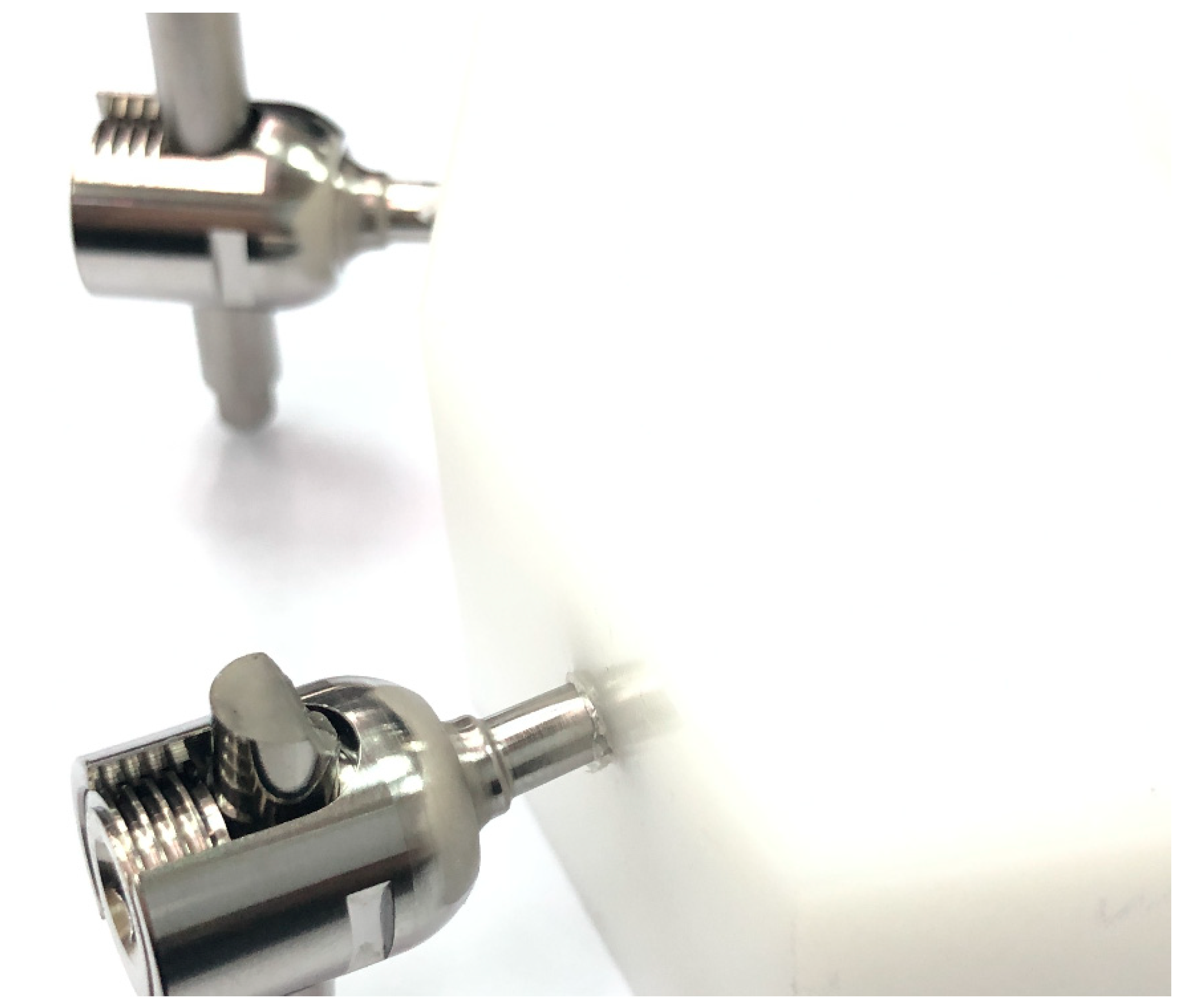
2.1. Mechanical Fatigue Testing

The test constructs were subjected to fatigue testing through dynamic bending in accordance with ASTM F1717. As shown in Figure 1a, each construct consisted of four pedicle screws (Ti-6Al-4V, 4.0 mm diameter, 30 mm length) and two titanium rods (Ti-6Al-4V, 5.5 mm diameter, 120 mm length) inserted into ultra-high molecular weight polyethylene (UHMWPE) test blocks to simulate a vertebrectomy. Both fully threaded (FT) and partially unthreaded (PU) pedicle screws were tested, and the screws and rods had been pre-treated by sandblasting and anodization. For the fatigue test, the UWMWPE blocks were clamped in an MTS 370 machine (MTS Systems Corporation, Eden Prairie, MN, USA) and a compressive force applied.
A previous study by our institute [16] determined the critical condition for pedicle screw insertion as having the threaded portion exposed by 1 or 2 threads to accommodate rod placement and ensure alignment between the tulip of the screw and the rod. Two different setups were evaluated (Figure 1b): (i) pedicle screw fully inserted into the test block with an exposed length of 3.6 mm [16] (EXP-FT-01 and EXP-PU-01) and (ii) pedicle screw inserted leaving 7.6 mm [16] of the screw shaft exposed (EXP-FT-02 and EXP-PU-02).
Loading was applied in a cyclic sine wave at a frequency of 5 Hz with a load ratio of 0.1 (minimum load divided by maximum load). Static testing was first used to determine the ultimate load for the EXP-FT-01 model as 340 N [16]. In accordance with ASTM F1717, loading for fatigue testing should begin at 50% of the ultimate load, which is 170 N for the EXP-FT-01 construct. Therefore, for all test setups (Figure 1b), loading began at 170 N and was incrementally increased after every third sample (170 N to 190 N to 220 N) until either the construct underwent permanent deformation or failed or the number of cycles reached 5,000,000 cycles. Otherwise, the load level was decreased every 3 samples until sample run-out. The maximum and minimum loads and the number of cycles sustained were used to calculate the fatigue strength for each test setup.

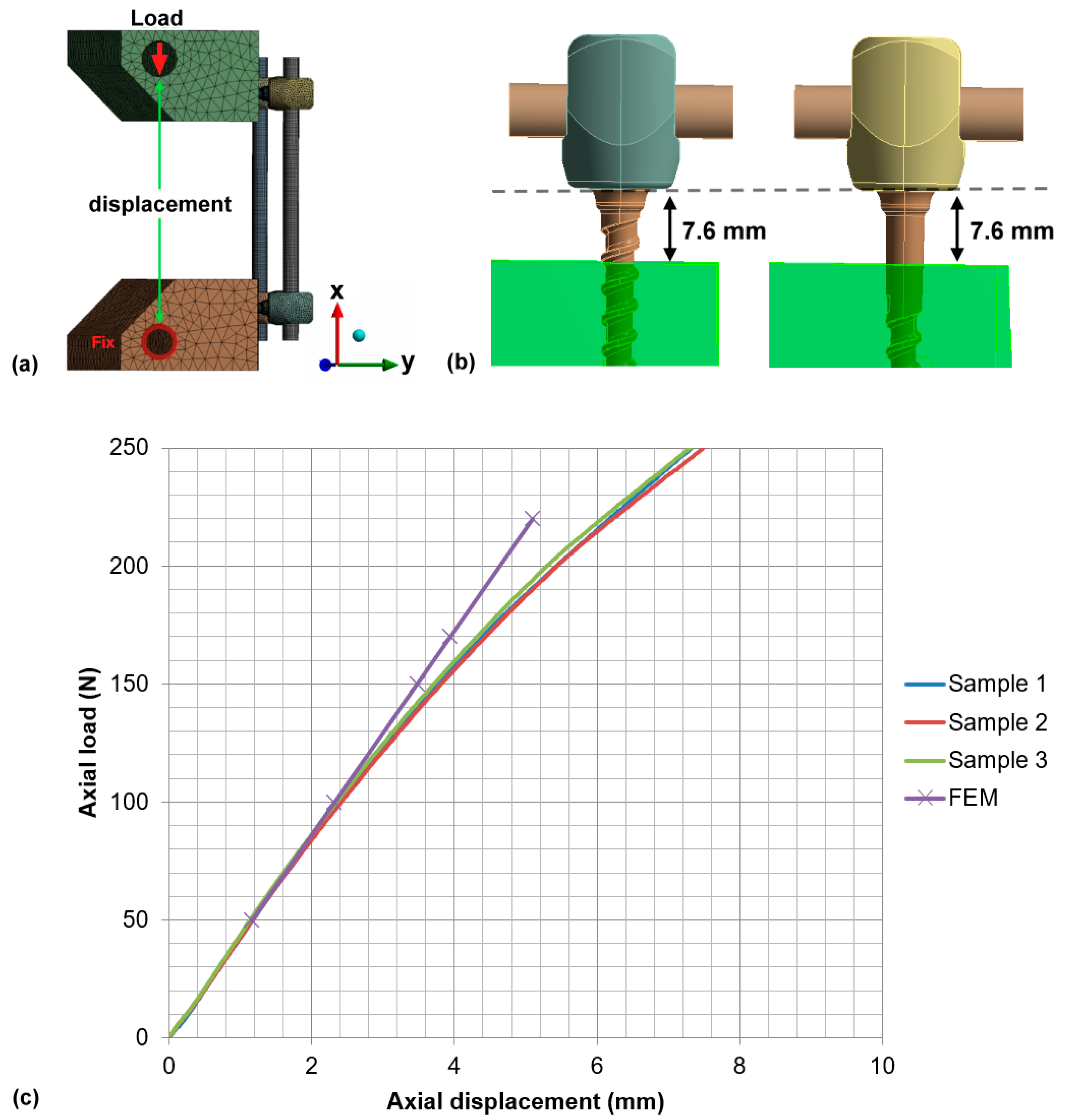
2.2. Finite Element Models

Four finite element models (FEM-FT-01, FEM-FT-02, FEM-PU-01, and FEM-PU-02) were created using the same boundary and loading conditions as the experimental fatigue test setup detailed above (Figure 2a,b). A vertical load was applied to the analytically rigid surface, which was inserted within the horizontal hole of the UHMWPE test block; the lower rigid surface was fixed [16]. These two rigid surfaces were assumed to have a frictionless contact with the test block. The contact interface between the screws and rods was bonded [18,19]. All meshing and simulations were conducted using ANSYS 16.0 (ANSYS Inc., Park City, UT, USA). The pedicle screws, support rods, and UHMWPE test blocks were modeled as linearly elastic materials with the properties detailed in Table 1 [16]. The rods were meshed using eight-node hexahedral elements, and the screws used four-node tetrahedral elements. A mesh sensitivity study was performed to ensure the convergence of the mesh solution. The final model had 72,471 elements in each rod, 38,541 elements in each fully threaded polyaxial screw (8582 and 30,059 for the head and body, respectively), and 36,437 elements in each proximally unthreaded polyaxial screw (8582 and 27,855 for the head and body, respectively). The UHMWPE block in the FEM-FT-01 and FEM-PU-01 models had 61,059 elements, and in the FEM-FT-02 and FEM-PU-02 models had 55,832 elements (Table 2). When placed under a 170 N vertical load, the mesh was assumed to converge when the change in von Mises stress on the screws and rods was less than 2%.
The FEM-FT-01 model was validated by demonstrating that the stiffness of the entire model (43.18 N/mm) was within the range of experimental data (42.78–43.72 N/mm), as shown in Figure 2c.

3. Results

3.1. Dynamic Compression Bending Test

Table 3 details the results of the dynamic bending compression test. The EXP-PU-01 construct was found to have the greatest fatigue strength of 220 N, while both the EXP-FT-01 and EXP-PU-02 groups had a lower fatigue strength of 190 N. In the fully threaded (FT) groups, the screw failed where it inserted into the UHMWPE block, whereas it was the rod that failed in the proximally unthreaded (PU) groups (Figure 3). Under a maximum load of 190 N, one sample from the EXP-PU-02 group survived to run-out (>5,000,000 cycles), which was superior to the EXP-FT-02 group, which had an average cycle count of 1,116,787 cycles.

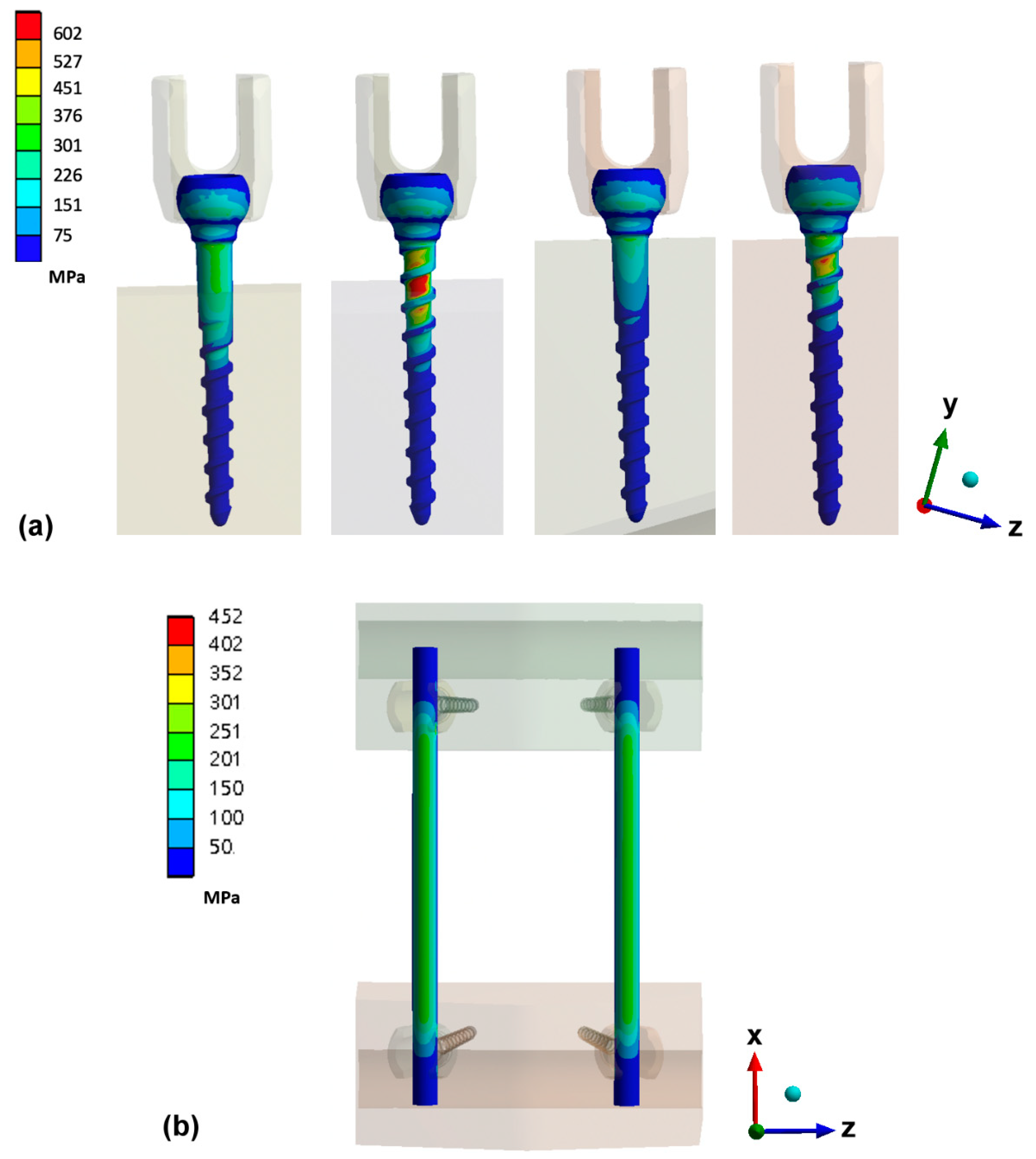
3.2. Maximum Von Mises Stress on Pedicle Screw and Rod

The maximum von Mises stress on the screws in the computational models appeared at the region where the screws entered the UHMWPE blocks (Figure 4a). The von Mises stress on the pedicle screws was recorded as 677.23 MPa, 1070.91 MPa, 385.809 MPa, and 491.50 MPa in the FEM-FT-01, FEM-FT-02, FEM-PU-01, and FEM-PU-02 models, respectively, when placed under an axial force of 170 N. When the load was increased to 220 N, the FEM-FT-02 model showed the highest von Mises stress on the pedicle screws (Table 4). For the rod component in the FEM-FT-01, FEM-FT-02, FEM-PU-01, and FEM-PU-02 models, the maximum von Mises stress was 341.66 MPa, 369.67 MPa, 361.36 MPa, and 362.24 MPa, respectively, under a 170 N axial load, and the maximum value occurred at the interface between screw and rod. When the load was increased to 220 N, the FEM-FT-02 model showed the highest von Mises stress on the rods (Figure 4b and Table 5). The maximum von Mises stress on the pedicle screws in the FEM-PU-01 and FEM-PU-02 models was 43% and 54% less than that in the FEM-FT-01 and FEM-FT-02 models, respectively, while the maximum von Mises stress on the rod component decreased by 1.4% in both models. The stiffness of the FEM-PU-01 (45.09 N/mm) and FEM-PU-02 (30.09 N/mm) models increased by 4.4% and 14.2%, respectively, in comparison to the FEM-FT-01 (43.18 N/mm) and FEM-FT-02 (26.34 N/mm) models. The stiffness of all FEM models was found to be similar to the results from the mechanical fatigue test (EXP-FT-01: 42.48 ± 0.42 N/mm; EXP-FT-02: 26.69 ± 0.63 N/mm; EXP-PU-01: 44.96 ± 0.71 N/mm; EXP-PU-02: 29.52 ± 0.93 N/mm).

4. Discussion

Fracture of pedicle screws can lead to considerable complications in the spine, such as loss of curvature and symptomatic pseudarthrosis, which often requires reoperation. Screw fracture mostly occurs following high-energy impact injuries or metal fatigue from repetitive stress. Chu et al. [16] demonstrated a reduction in the fatigue life and strength of pedicle screws when a portion of the screw threads was left exposed outside of the bone. This is echoed in the results of this study, where the EXP-FT-02 construct clearly had the lowest fatigue strength of all groups. However, Table 3 also shows that by omitting threads from the exposed portion of the screw (1/3 proximally unthreaded), the fatigue strength increased in comparison to a fully threaded screw.
It is worth noting that the fatigue life of EXP-PU-02 was higher than EXP-FT-01, signifying that the fatigue strength of the proximally unthreaded (PU) screw when not fully inserted is higher than the fully threaded (FT) screw when fully inserted into the test block. In addition, whereas the construct with fully threaded screws failed through screw fracture, the construct with PU screws failed by fracture of the rods. This shows that the unthreaded portion (shank) of the PU screw plays an important role in the fatigue life and supports the hypothesis of this study that the fatigue strength would be superior to a fully threaded screw. A possible contributing factor to the greater fatigue strength is the diameter of the screw. The smooth shank on the PU screw had a diameter of 4.0 mm, whereas the inner/minor diameter of the fully threaded screw was 3.0 mm. The second axial moment of area of the PU screw was greater than the fully threaded screw at the point where the screws entered the test block. This might contribute to the better fatigue bending strength.
According to Chen et al. [20], the most stressed site on a pedicle screw is the junction between the shank and threads, and the threads at the screw–bone interface tend to be less stressed than threads outside the interface. This is consistent with the findings of this study. Whether considering the FT or PU screw, the major stress occurred on the proximal part of screw, and the maximum von Mises stress occurred at the interface between the screw and the block. In all of the FT screw groups, the maximum von Mises stress on the screw exceeded that on the rod. Previous studies [20,21,22] have demonstrated an increase in stress at the screw head and a loss in fatigue strength with increasing unsupported screw length, which is consistent with the findings of this study. The FE model demonstrated that in comparison to the FT screw, the PU screw design produced a lower maximum von Mises stress on the screw and provided superior fatigue strength when partially inserted. This was supported by the fact that it was the rod rather than the screw that fractured during the dynamical compression test.
Despite the clearly superior results obtained from the proximally unthreaded screw in this study, there are some limitations to the methods used. (i) The vertebrectomy model was developed in compliance with ASTM F1717, which is the correct approach to use for this form of study [22,23,24]. However, the simplifications incorporated into any such model cannot truly represent the multidirectional loading conditions in a normal human spine. (ii) Similarly, the finite element models were subjected to a single vertical load on a specific point on the test block to validate the models, but again this is a gross simplification against in vivo conditions in the spine. Future studies may consider incorporating a wider range of forces. The computational model was also simplified to assign all constructs with linearly elastic homogeneous isotropic properties with all contact interfaces bonded. These assumptions are simplifications of the real situation, where the insertion of the pedicle screw within the UHMWPE block would produce an initial residual stress/damage on the surrounding of the UHMWPE block (plastic deformed) [23], which increased the displacement in the experiments and showed non-linear behavior (Figure 2c). These assumptions also result in a stiffer construct and linear behavior of load displacement in the finite element model, as shown in Figure 2c. (iii) Different screw sizes or thread designs were also not considered in this study because the primary goal was to analyze how incomplete insertion of the proximally unthreaded pedicle screw compared to a standard fully threaded pedicle screw in terms of stress and fatigue life.

5. Conclusions

The results of this study show that the 1/3 proximally unthreaded (PU) pedicle screw design offers superior fatigue strength and fatigue life over a traditional fully threaded pedicle screw during both partial and full insertion. The PU pedicle screw can not only reduce the risk of screw fatigue failure but also increase implant survival when used in deformed or degenerated segments where the pedicle screws need to be exposed by one or multiple threads to accommodate rod placement.

Author Contributions

Conceptualization, F.-Y.T., C.-H.C. and C.-J.C.; methodology, F.-Y.T., Y.-J.K. and Y.-Y.H.; project administration, C.-H.C. and C.-J.C.; resources, C.-H.C. and L.-C.W.; software, F.-Y.T. and L.-C.W.; validation, F.-Y.T., C.-H.C., Y.-J.K. and C.-J.C.; writing—original draft, F.-Y.T.; writing—review and editing, F.-Y.T., Y.-J.K. and C.-J.C. All authors have read and agreed to the published version of the manuscript.

Funding

This research received no external funding.

Institutional Review Board Statement

Not applicable.

Informed Consent Statement

Not applicable.

Data Availability Statement

All relevant data are within the manuscript.

Acknowledgments

Not applicable.

Conflicts of Interest

The authors declare no conflict of interest.

References

  1. Dvorak, M.F.; Pitzen, T.; Zhu, Q.; Gordon, J.D.; Fisher, C.G.; Oxland, T.R. Anterior cervicalplate fixation: A biomechanical study to evaluate the effects of plate design, endplate preparation, and bone mineral density. Spine 2005, 30, 294–301. [Google Scholar] [CrossRef]
  2. Ramaswamy, R.; Evans, S.; Kosashvili, Y. Holding power of variable pitch screws inosteoporotic, osteopenic and normal bone: Are all screws created equal? Injury 2010, 41, 179–183. [Google Scholar] [CrossRef]
  3. Halvorson, T.L.; Kelley, L.A.; Thomas, K.A.; Whitecloud, T.S., III; Cook, S.D. Effects of bone mineral density on pedicle screw fixation. Spine 1994, 19, 2415–2420. [Google Scholar] [CrossRef]
  4. Lattig, F. Bone cement augmentation in the prevention of adjacent segment failure after multilevel adult deformity fusion. J. Spinal Disord. Tech. 2009, 22, 439–443. [Google Scholar] [CrossRef] [PubMed]
  5. Par’e, P.E.; Chappuis, J.L.; Rampersaud, R.; Agarwala, A.O.; Perra, J.H.; Erkan, S.; Wu, C. Biomechanical evaluation of a novel fenestrated pedicle screw augmented with bone cement in osteoporotic spines. Spine 2011, 36, E1210–E1214. [Google Scholar] [CrossRef]
  6. Kayanja, M.; Evans, K.; Milks, R.; Lieberman, I.H. The mechanics of polymethyl-methacrylate augmentation. Clin. Orthop. Relat. Res. 2006, 443, 124–130. [Google Scholar] [CrossRef]
  7. Chen, L.-H.; Tai, C.-L.; Lai, P.-L.; Lee, D.-M.; Tsai, T.-T.; Fu, T.-S.; Niu, C.-C.; Chen, W.-J. Pullout strength for cannulated pedicle screws with bone cement augmentation in severely osteoporotic bone: Influences of radial hole and pilot hole tapping. Clin. Biomech. 2009, 24, 613–618. [Google Scholar] [CrossRef]
  8. Klingler, J.-H.; Scholz, C.; Kogias, E.; Sircar, R.; Krüger, M.T.; Volz, F.; Scheiwe, C.; Hubbe, U. Minimally Invasive Technique for PMMA Augmentation of Fenestrated Screws. Sci. World J. 2015, 2015, 1–7. [Google Scholar] [CrossRef] [PubMed]
  9. Mueller, J.U.; Baldauf, J.; Marx, S.; Kirsch, M.; Schroeder, H.W.; Pillich, D.T. Cement leakage in pedicle screw augmentation: A pro-spective analysis of 98 patients and 474 augmented pedicle screws. J. Neurosurg. Spine 2016, 25, 103–109. [Google Scholar] [CrossRef] [PubMed]
  10. Patel, P.S.; Shepherd, D.E.; Hukins, D.W. The effect of screw insertion angle and thread type on the pullout strength of bone screws in normal and osteoporotic cancellous bone models. Med. Eng. Phys. 2010, 32, 822–828. [Google Scholar] [CrossRef] [PubMed]
  11. Zindrick, M.R.; Wiltse, L.L.; Widell, E.H.; Thomas, J.C.; Holland, W.R.; Field, B.T.; Spencer, C.W. A biomechanical study of intrapeduncular screw fixation in the lumbosacral spine. Clin. Orthop. Relat. Res. 1986, 203, 99–112. [Google Scholar] [CrossRef]
  12. Weinstein, J.N.; Rydevik, B.L.; Rauschning, W. Anatomic and technical considerations of pedicle screw fixation. Clin. Orthop. Relat. Res. 1992, 284, 34–46. [Google Scholar] [CrossRef]
  13. Krenn, M.H.; Piotrowski, W.P.; Penzkofer, R.; Augat, P. Influence of thread design on pedicle screwfixation: Laboratory investi-gation. J. Neurosurg. Spine 2008, 9, 90–95. [Google Scholar] [CrossRef]
  14. Varghese, V.; Krishnan, V.; Kumar, G.S. Comparison of pullout strength of pedicle screws following revision using larger di-ameter screws. Med. Eng. Phys. 2019, 74, 180–185. [Google Scholar] [CrossRef] [PubMed]
  15. Tsuang, F.-Y.; Chen, C.-H.; Wu, L.-C.; Kuo, Y.-J.; Lin, S.-C.; Chiang, C.-J. Biomechanical arrangement of threaded and unthreaded portions providing holding power of transpedicular screw fixation. Clin. Biomech. 2016, 39, 71–76. [Google Scholar] [CrossRef] [PubMed] [Green Version]
  16. Chu, Y.L.; Chen, C.H.; Tsuang, F.Y.; Chiang, C.J.; Wu, Y.; Kuo, Y.J. Incomplete insertion of pedicle screws in a standard construct re-duces the fatigue life: A biomechanical analysis. PLoS ONE 2019, 14, e0224699. [Google Scholar] [CrossRef] [PubMed]
  17. ASTM F1717-18. Standard Test Methods for Spinal Implant Constructs in a Vertebrectomy Model. ASTM Int West Con-Shohocken, PA [Internet], 2018; pp. 1–16. Available online: https://www.astm.org/Standards/F1717.htm (accessed on 11 March 2019).
  18. Galbusera, F.; Schmidt, H.; Wilke, H.-J. Lumbar interbody fusion: A parametric investigation of a novel cage design with and without posterior instrumentation. Eur. Spine J. 2011, 21, 455–462. [Google Scholar] [CrossRef] [Green Version]
  19. Schmidt, H.; Heuer, F.; Wilke, H.-J. Which axial and bending stiffnesses of posterior implants are required to design a flexible lumbar stabilization system? J. Biomech. 2009, 42, 48–54. [Google Scholar] [CrossRef] [PubMed]
  20. Chen, C.-S.; Chen, W.-J.; Cheng, C.-K.; Jao, S.-H.E.; Chueh, S.-C.; Wang, C.-C. Failure analysis of broken pedicle screws on spinal in-strumentation. Med. Eng. Phys. 2005, 27, 487–496. Available online: http://www.ncbi.nlm.nih.gov/pubmed/15990065 (accessed on 28 March 2019). [CrossRef]
  21. La Barbera, L.; Galbusera, F.; Wilke, H.-J.; Villa, T. Preclinical evaluation of posterior spine stabilization devices: Can we compare in vitro and in vivo loads on the instrumentation? Eur. Spine J. 2016, 26, 200–209. [Google Scholar] [CrossRef] [Green Version]
  22. La Barbera, L.; Galbusera, F.; Wilke, H.-J.; Villa, T. Preclinical evaluation of posterior spine stabilization devices: Can the current standards represent basic everyday life activities? Eur. Spine J. 2016, 25, 2909–2918. Available online: http://www.ncbi.nlm.nih.gov/pubmed/27236658 (accessed on 10 April 2019). [CrossRef] [PubMed] [Green Version]
  23. La Barbera, L.; Galbusera, F.; Villa, T.; Costa, F.; Wilke, H.-J. ASTM F1717 standard for the preclinical evaluation of posterior spi-nal fixators: Can we improve it? Proc. Inst. Mech. Eng. Part H J. Eng. Med. 2014, 228, 1014–1026. Available online: http://www.ncbi.nlm.nih.gov/pubmed/25319550 (accessed on 16 March 2019). [CrossRef] [PubMed] [Green Version]
  24. Stanford, R.E.; Loefler, A.H.; Stanford, P.M.; Walsh, W.R. Multiaxial Pedicle Screw Designs: Static and Dynamic Mechanical Testing. Spine 2004, 29, 367–375. [Google Scholar] [CrossRef] [PubMed]
Figure 1. (a) American Society for Testing and Materials (ASTM) F1717 standard configuration. (b) Two different setups were evaluated: (i) pedicle screw fully inserted into the test block with an exposed length of 3.6 mm (EXP-FT-01 and EXP-PU-01) and (ii) pedicle screw inserted leaving 7.6 mm of the screw shaft exposed (EXP-FT-02 and EXP-PU-02).
Applsci 11 01503 g001
Figure 2. (a) Finite element model in accordance with ASTM F1717 standard configuration. (b) Pedicle screw inserted leaving 7.6 mm unsupported length (FEM-FT-02 and FEM-PU-02). (c) The axial displacement and load curve of experimental data of EXP-FT-01 and finite element model FEM-FT-01.
Applsci 11 01503 g002
Figure 3. Rod failed in the proximally unthreaded (PU) groups in the dynamic compression bending test.
Applsci 11 01503 g003
Figure 4. The distribution of the maximum von Mises stress on (a) pedicle screws of four models and (b) rods of the FEM-FT-01 model under 170 N axial loading.
Applsci 11 01503 g004
Table 1. Material properties of finite element models.
Modulus (MPa)ν
Ultra-high molecular weight polyethylene (UHMWPE) blocks [16]10500.4
Titanium rods [16]110,0000.3
Titanium pedicle screws [16]110,0000.3
Table 2. Type of elements, number of elements, and nodes in each part of the finite element models.
Fully Threaded Polyaxial Screw (Head/Body)Proximally Unthreaded Polyaxial Screw (Head/Body)UHMWPE Block of FEM-FT-01 and FEM-PU-01UHMWPE Block of FEM-FT-02 and FEM-PU-02Rod
Type of elements4-node tetrahedral8-node hexahedron
Number of elements8582/30,0598582/27,85561,05955,83272,471
Number of nodes15,448/54,40715,448/49,582109,29699,381289,878
Table 3. Results of the dynamic compression bending test.
Min. and Max. of Axial Force17–170 (N)19–190 (N)22–220 (N)
GroupNo. of samplesCyclesNo. of samplesCyclesNo. of samplescycles
EXP-FT-011Run-out4Run-out7719,021 *
2Run-out5Run-out8791,733 *
3Run-out6Run-out9736,885 *
EXP-FT-0210Run-out131,361,467 *1618,209 *
11Run-out14971,656 *1721,779 *
12Run-out151,017,237 *187562 *
EXP-PU-0119Run-out22Run-out25Run-out
20Run-out23Run-out26Run-out
21Run-out24Run-out27Run-out
EXP-PU-0228Run-out31Run-out344,152,887 **
29Run-out32Run-out354,001,455 **
30Run-out33Run-out36Run-out
* Pedicle screw fracture; ** rod fracture; run-out: run out at 5 million cycles.
Table 4. Maximum von Mises stress on pedicle screws.
Axial Force (N)170220
Screw of FEM-FT-01 (MPa)677.23875.23
Screw of FEM-FT-02 (MPa)1070.911384.01
Screw of FEM-PU-01 (MPa)385.89498.71
Screw of FEM-PU-02 (MPa)491.5635.20
Table 5. Maximum von Mises stress on rods.
Axial Force (N)170220
Rod of FEM-FT-01 (MPa)341.66440.12
Rod of FEM-FT-02 (MPa)369.67475.36
Rod of FEM-PU-01 (MPa)361.36465.49
Rod of FEM-PU-02 (MPa)362.24468.78
Publisher’s Note: MDPI stays neutral with regard to jurisdictional claims in published maps and institutional affiliations.

