Three-Dimensional Finite Element Analysis of Stress Distribution in a Tooth Restored with Full Coverage Machined Polymer Crown


Abstract
1. Introduction
2. Materials and Methods
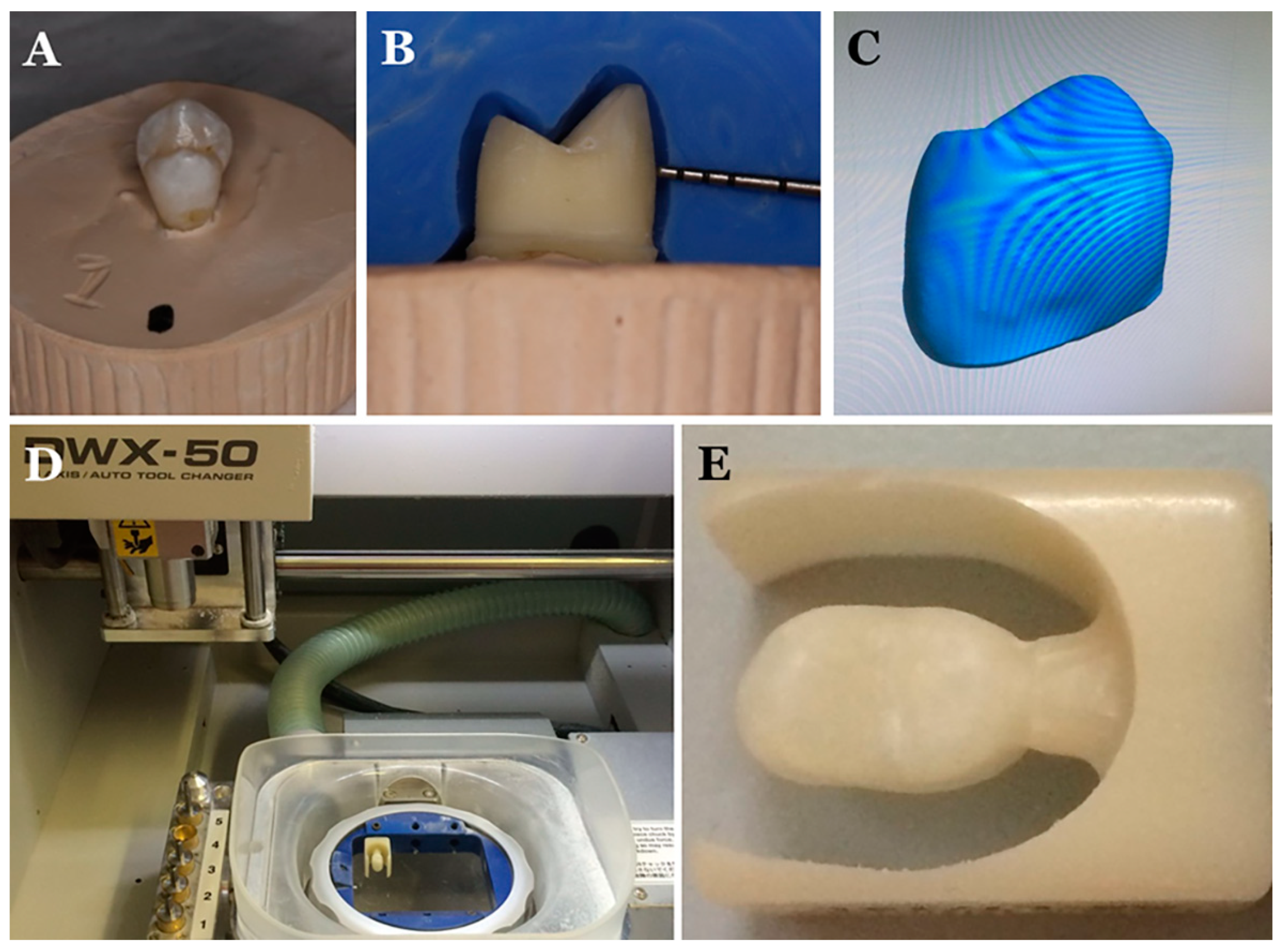
2.1. Preparation of Bonded Crown–Tooth complex
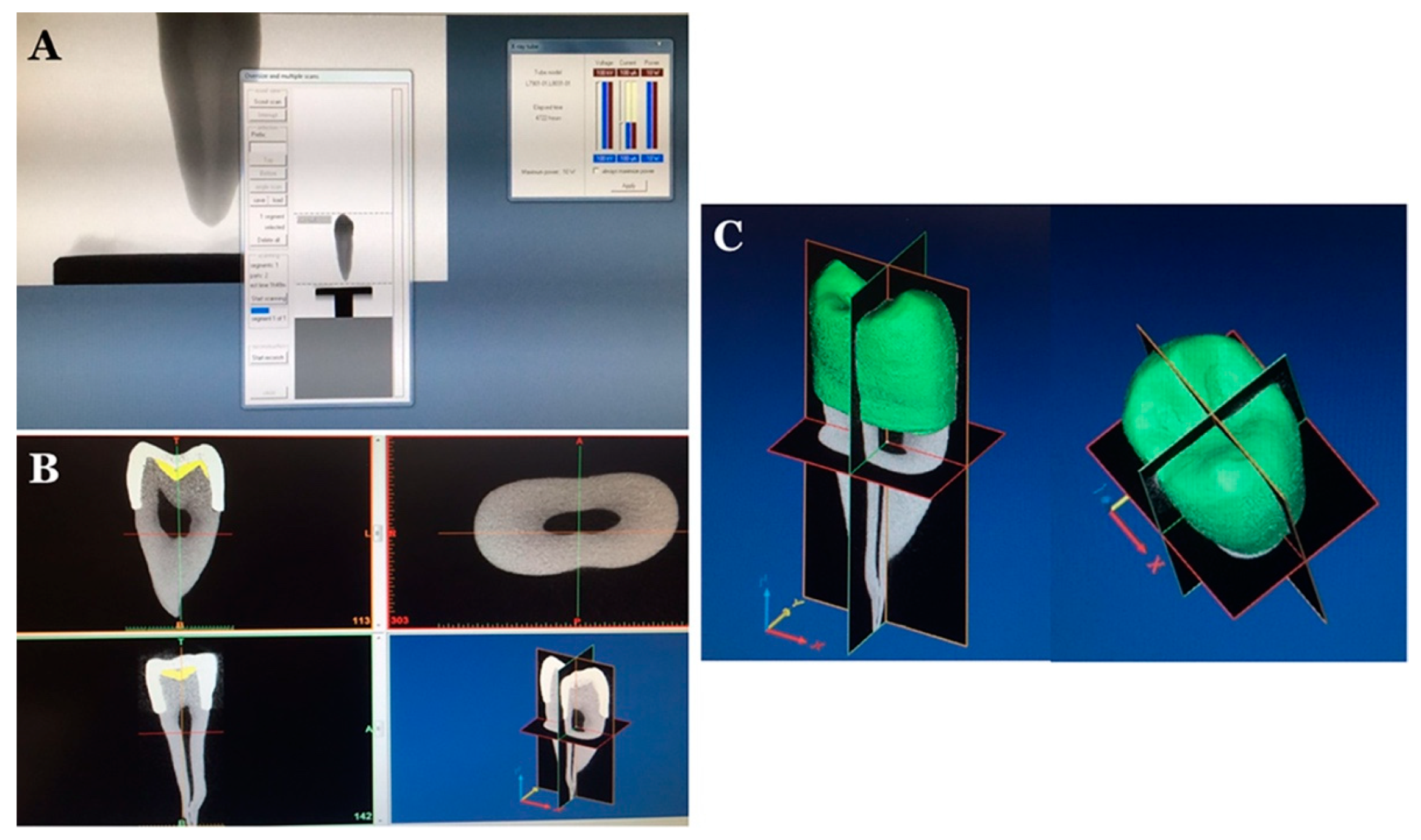
2.2. Finite Element Model Preparation
2.3. Material Associated Properties
2.4. Interface Association
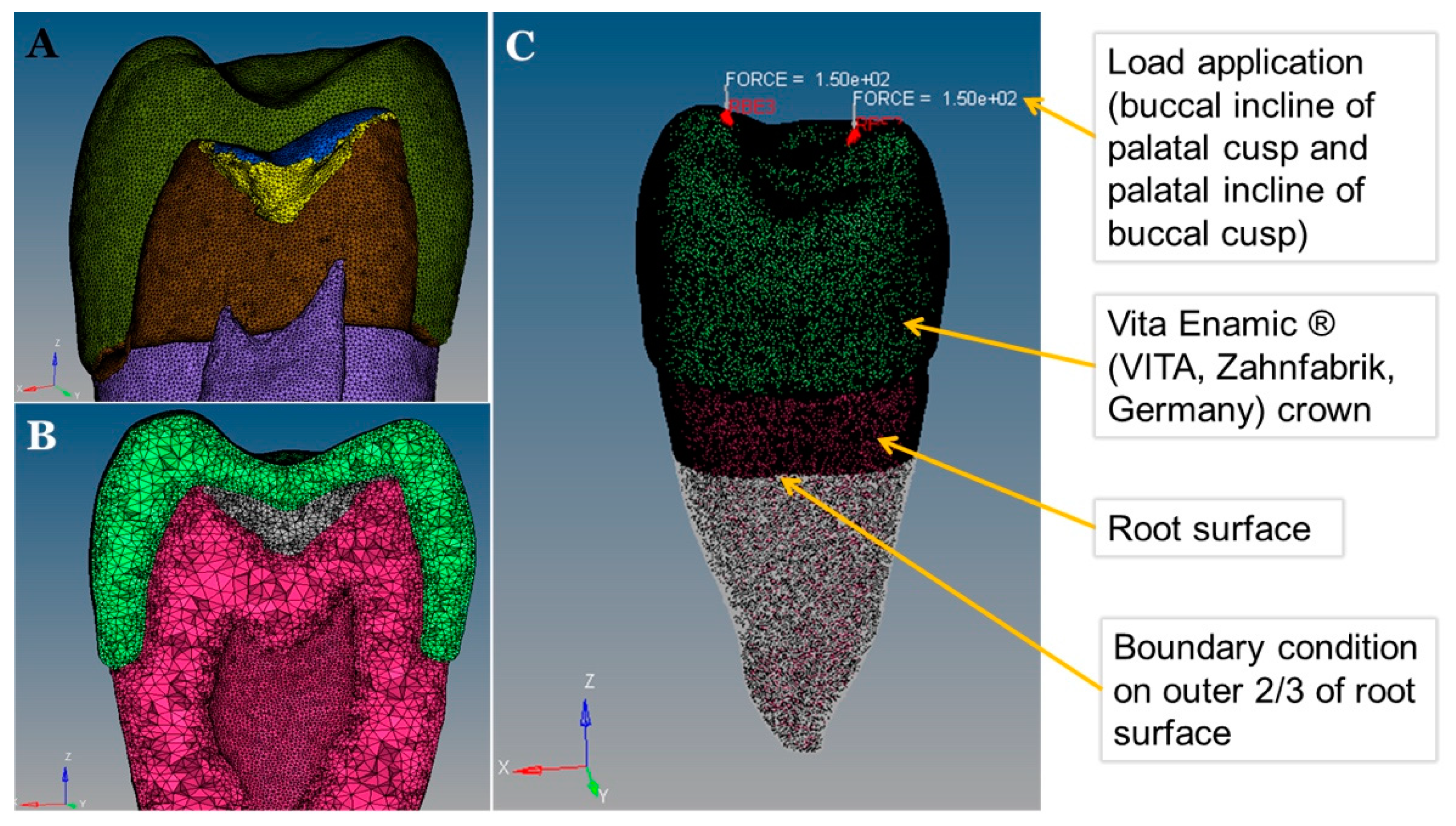
2.5. Boundary Condition and Load Application on the FE Model
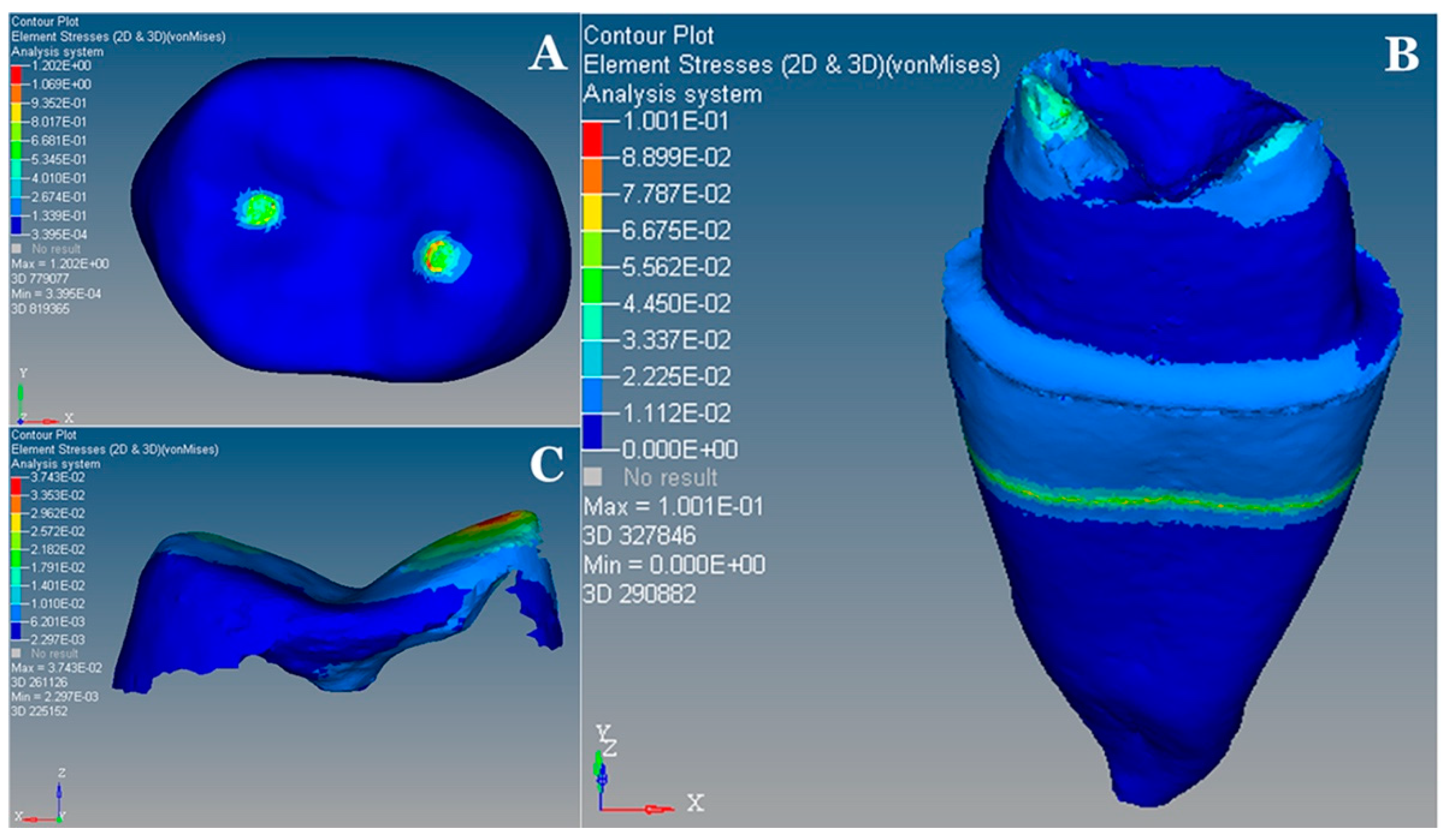
3. Results
4. Discussion
5. Conclusions
Author Contributions
Funding
Institutional Review Board Statement
Informed Consent Statement
Data Availability Statement
Acknowledgments
Conflicts of Interest
References
- Yahyazadehfar, M.; Ivancik, J.; Majd, H.; An, B.; Zhang, D.; Arola, D. On the Mechanics of Fatigue and Fracture in Teeth. Appl. Mech. Rev. 2014, 66, 030803. [Google Scholar] [CrossRef]
- Rokaya, D.; Mahat, Y.; Sapkota, B.; Kc, B.S. Full Coverage Crowns and Resin-bonded Bridge Combination for Missing Mandibular Anterior Teeth. Kathmandu Univ. Med. J. 2018, 16, 97–99. [Google Scholar]
- Kuroe, T.; Itoh, H.; Caputo, A.A.; Konuma, M. Biomechanics of cervical tooth structure lesions and their restoration. Quintessence Int. 2000, 31, 267–274. [Google Scholar]
- Poggio, C.E.; Ercoli, C.; Rispoli, L.; Maiorana, C.; Esposito, M. Metal-free materials for fixed prosthodontic restorations. Cochrane Database Syst. Rev. 2017, 12, CD009606. [Google Scholar] [CrossRef]
- Dérand, T. Stress analysis of cemented or resin-bonded loaded porcelain inlays. Dent. Mater. 1991, 7, 21–24. [Google Scholar] [CrossRef]
- Ioannidis, A.; Mühlemann, S.; Özcan, M.; Hüsler, J.; Hämmerle, C.H.F.; Benic, G.I. Ultra-thin occlusal veneers bonded to enamel and made of ceramic or hybrid materials exhibit load-bearing capacities not different from conventional restorations. J. Mech. Behav. Biomed. Mater. 2019, 90, 433–440. [Google Scholar] [CrossRef]
- Wang, W.C.; McDonald, A.; Petrie, A.; Setchell, D. Interface dimensions of CEREC-3 MOD onlays. Eur. J. Prosthodont. Restor. Dent. 2007, 15, 183–189. [Google Scholar]
- Abe, Y.; Lambrechts, P.; Inoue, S.; Braem, M.J.A.; Takeuchi, M.; Vanherle, G.; Van Meerbeek, B. Dynamic elastic modulus of ‘packable’ composites. Dent. Mater. 2001, 17, 520–525. [Google Scholar]
- Humagain, M.; Rokaya, D. Integrating Digital Technologies in Dentistry to Enhance the Clinical Success. Kathmandu Univ. Med. J. 2019, 17, 256–257. [Google Scholar]
- Heck, K.; Paterno, H.; Lederer, A.; Litzenburger, F.; Hickel, R.; Kunzelmann, K.H. Fatigue resistance of ultrathin CAD/CAM ceramic and nanoceramic composite occlusal veneers. Dent. Mater. 2019, 35, 1370–1377. [Google Scholar] [CrossRef]
- Mahler, D.B.; Peyton, F.A. Photoelasticity as a research technique for analyzing stresses in dental structures. J. Dent. Res. 1955, 34, 831–838. [Google Scholar] [CrossRef]
- El-Ebrashi, M.K.; Craig, R.G.; Peyton, F.A. Experimental stress analysis of dental restorations. VII. Structural design and stress analysis of fixed partial dentures. J. Prosthet. Dent. 1970, 23, 177–186. [Google Scholar] [CrossRef]
- Zhang, Y.; Sailer, I.; Lawn, B.R. Fatigue of dental ceramics. J. Dent. 2013, 41, 1135–1147. [Google Scholar] [CrossRef]
- Romeed, S.A.; Fok, S.L.; Wilson, N.H.F. A comparison of 2D and 3D finite element analysis of a restored tooth. J. Oral Rehabil. 2006, 33, 209–215. [Google Scholar] [CrossRef]
- Ausiello, P.; Apicella, A.; Davidson, C.L. Effect of adhesive layer properties on stress distribution in composite restorations--a 3D finite element analysis. Dent. Mater. 2002, 18, 295–303. [Google Scholar] [CrossRef]
- Lin, P.-J.; Su, K.-C. Biomechanical Design Application on the Effect of Different Occlusion Conditions on Dental Implants with Different Positions—A Finite Element Analysis. Appl. Sci. 2020, 10, 5826. [Google Scholar] [CrossRef]
- Amornvit, P.; Rokaya, D.; Keawcharoen, K.; Thongpulsawasdi, N. Stress distribution in implant retained finger prosthesis: A finite element study. J. Clin. Diagn. Res. 2013, 7, 2851–2854. [Google Scholar] [CrossRef]
- Dawood, S.N.; Al-Zahawi, A.R.; Sabri, L.A. Mechanical and Thermal Stress Behavior of a Conservative Proposed Veneer Preparation Design for Restoring Misaligned Anterior Teeth: A 3D Finite Element Analysis. Appl. Sci. 2020, 10, 5814. [Google Scholar] [CrossRef]
- Farah, J.W.; Craig, R.G. Distribution of stresses in porcelain-fused-to-metal and porcelain jacket crowns. J. Dent. Res. 1975, 54, 255–261. [Google Scholar]
- Bruno, G.; de Stefani, A.; Caragiuli, M.; Zalunardo, F.; Mazzoli, A.; Landi, D.; Mandolini, M.; Gracco, A. Comparison of the Effects Caused by Three Different Mandibular Advancement Devices on the Periodontal Ligaments and Teeth for the Treatment of Osa: A Finite Element Model Study. Appl. Sci. 2020, 10, 6932. [Google Scholar] [CrossRef]
- Wang, Y.-T.; Chen, C.-H.; Wang, P.-F.; Chen, C.-T.; Lin, C.-L. Design of a Metal 3D Printing Patient-Specific Repairing Thin Implant for Zygomaticomaxillary Complex Bone Fracture Based on Buttress Theory Using Finite Element Analysis. Appl. Sci. 2020, 10, 4738. [Google Scholar] [CrossRef]
- Boschian Pest, L.; Guidotti, S.; Pietrabissa, R.; Gagliani, M. Stress distribution in a post-restored tooth using the three-dimensional finite element method. J. Oral Rehabil. 2006, 33, 690–697. [Google Scholar] [CrossRef]
- Versluis, A.; Tantbirojn, D.; Pintado, M.R.; DeLong, R.; Douglas, W.H. Residual shrinkage stress distributions in molars after composite restoration. Dent. Mater. 2004, 20, 554–564. [Google Scholar] [CrossRef] [PubMed]
- Tsitrou, E.A.; van Noort, R. Minimal preparation designs for single posterior indirect prostheses with the use of the Cerec system. Int. J. Comput. Dent. 2008, 11, 227–240. [Google Scholar] [PubMed]
- Zahnfabrik, V. Bad Säckingen, Germany: Vita Zahnfabrik. 2020. Available online: https://www.vita-zahnfabrik.com/ (accessed on 18 January 2021).
- RelyX™Ultimate Technical Data. 3M ESPE. Saint Paul, MN, USA, 2020. Available online: https://multimedia.3m.com/mws/media/783784O/3m-relyx-ultimate-adhesive-resin-cement-technical-data-sheet.pdf (accessed on 18 January 2021).
- Chen, Y.-C.; Tsai, H.-H. Use of 3D finite element models to analyze the influence of alveolar bone height on tooth mobility and stress distribution. J. Dent. Sci. 2011, 6, 90–94. [Google Scholar] [CrossRef]
- Yoshida, N.; Koga, Y.; Peng, C.-L.; Tanaka, E.; Kobayashi, K. In vivo measurement of the elastic modulus of the human periodontal ligament. Med. Eng. Phys. 2001, 23, 567–572. [Google Scholar] [CrossRef]
- Sinthaworn, S.; Puengpaiboon, U.; Warasetrattana, N.; Wanapaisarn, S. Estimation of Ultimate Tensile Strength of dentin Using Finite Element Analysis from Endodontically Treated Tooth. In IOP Conference Series: Materials Science and Engineering; IOP Publishing Ltd.: Bristol, UK, 2018; Volume 303, p. 012008. [Google Scholar]
- Shahrbaf, S.; vanNoort, R.; Mirzakouchaki, B.; Ghassemieh, E.; Martin, N. Effect of the crown design and interface lute parameters on the stress-state of a machined crown–tooth system: A finite element analysis. Dent. Mater. 2013, 29, e123–e131. [Google Scholar] [CrossRef]
- Ausiello, P.; Rengo, S.; Davidson, C.L.; Watts, D.C. Stress distributions in adhesively cemented ceramic and resin-composite Class II inlay restorations: A 3D-FEA study. Dent. Mater. 2004, 20, 862–872. [Google Scholar] [CrossRef]
- Palamara, D.; Palamara, J.E.; Tyas, M.J.; Messer, H.H. Strain patterns in cervical enamel of teeth subjected to occlusal loading. Dent. Mater. 2000, 16, 412–419. [Google Scholar] [CrossRef]
- Laouafa, F.; Royis, P. An iterative algorithm for finite element analysis. Comput. Appl. Math. 2004, 164–165, 469–491. [Google Scholar] [CrossRef][Green Version]
- Simşek, B.; Erkmen, E.; Yilmaz, D.; Eser, A. Effects of different inter-implant distances on the stress distribution around endosseous implants in posterior mandible: A 3D finite element analysis. Med Eng. Phys. 2006, 28, 199–213. [Google Scholar] [CrossRef] [PubMed]
- Yamanel, K.; Caglar, A.; Gülsahi, K.; Ozden, U.A. Effects of different ceramic and composite materials on stress distribution in inlay and onlay cavities: 3-D finite element analysis. Dent. Mater. J. 2009, 28, 661–670. [Google Scholar] [CrossRef] [PubMed]
- De Jager, N.; de Kler, M.; van der Zel, J.M. The influence of different core material on the FEA-determined stress distribution in dental crowns. Dent. Mater. 2006, 22, 234–242. [Google Scholar] [CrossRef] [PubMed]
- May, L.G.; Kelly, J.R.; Bottino, M.A.; Hill, T. Effects of cement thickness and bonding on the failure loads of CAD/CAM ceramic crowns: Multi-physics FEA modeling and monotonic testing. Dent. Mater. 2012, 28, e99–e109. [Google Scholar] [CrossRef]
- Dejak, B.; Mlotkowski, A. Three-dimensional finite element analysis of strength and adhesion of composite resin versus ceramic inlays in molars. J. Prosthet. Dent. 2008, 99, 131–140. [Google Scholar] [CrossRef]
- Oyar, P.; Ulusoy, M.; Eskitascioglu, G. Finite element analysis of stress distribution of 2 different tooth preparation designs in porcelain-fused-to-metal crowns. Int. J. Prosthod. 2006, 19, 85–91. [Google Scholar]
- Ausiello, P.; Franciosa, P.; Martorelli, M.; Watts, D.C. Mechanical behavior of post-restored upper canine teeth: A 3D FE analysis. Dent. Mater. 2011, 27, 1285–1294. [Google Scholar] [CrossRef]


| Tooth Reduction | Vita Enamic® (VITA, Zahnfabrik, Germany) Manufacturer’s Protocol |
|---|---|
| Occlusal reduction | Should be at least 1.5 mm |
| Bucco-labial or linguo-palatal reduction | At the bottom of the fissure: at least 1 mm, In the area of the cusps at least 1.5 mm |
| Margin all around | 0.8 to 1.5 mm |
| Materials | Modulus of Elasticity (MPa) | Poisson’s Ratio | Reference |
|---|---|---|---|
| Vita Enamic® (VITA Zahnfabrik, Bad Sackingen, Germany) | 30,000 | 0.23 | [25] |
| (Rely X U200, 3M ESPE Dental Products, St. Paul, MN, USA) | 7700 | 0.30 | [26] |
| Enamel | 84,100 | 0.30 | [27] |
| Dentine | 18,600 | 0.31 | [28,29] |
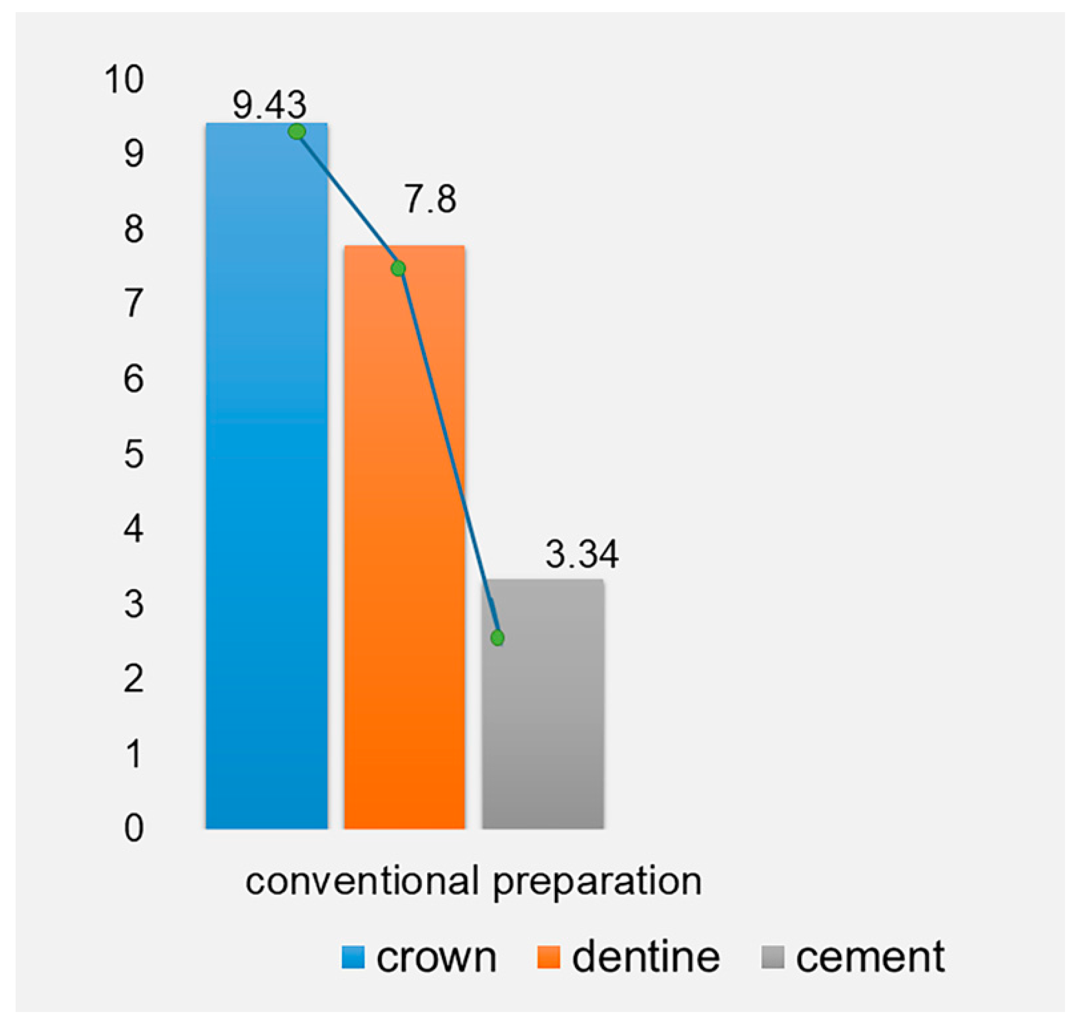
| Vita Enamic Crown layer | Dentine Layer | Cement Layer |
|---|---|---|
| Von Mises Stress (MPa) | Von Mises Stress (MPa) | Von Mises Stress (MPa) |
| 9.43 | 7.80 | 3.34 |
Publisher’s Note: MDPI stays neutral with regard to jurisdictional claims in published maps and institutional affiliations. |
© 2021 by the authors. Licensee MDPI, Basel, Switzerland. This article is an open access article distributed under the terms and conditions of the Creative Commons Attribution (CC BY) license (http://creativecommons.org/licenses/by/4.0/).
Share and Cite
Syed, A.U.Y.; Rokaya, D.; Shahrbaf, S.; Martin, N. Three-Dimensional Finite Element Analysis of Stress Distribution in a Tooth Restored with Full Coverage Machined Polymer Crown. Appl. Sci. 2021, 11, 1220. https://doi.org/10.3390/app11031220
Syed AUY, Rokaya D, Shahrbaf S, Martin N. Three-Dimensional Finite Element Analysis of Stress Distribution in a Tooth Restored with Full Coverage Machined Polymer Crown. Applied Sciences. 2021; 11(3):1220. https://doi.org/10.3390/app11031220
Chicago/Turabian StyleSyed, Azeem Ul Yaqin, Dinesh Rokaya, Shirin Shahrbaf, and Nicolas Martin. 2021. "Three-Dimensional Finite Element Analysis of Stress Distribution in a Tooth Restored with Full Coverage Machined Polymer Crown" Applied Sciences 11, no. 3: 1220. https://doi.org/10.3390/app11031220
APA StyleSyed, A. U. Y., Rokaya, D., Shahrbaf, S., & Martin, N. (2021). Three-Dimensional Finite Element Analysis of Stress Distribution in a Tooth Restored with Full Coverage Machined Polymer Crown. Applied Sciences, 11(3), 1220. https://doi.org/10.3390/app11031220