Abstract
The article deals with the theoretical description and experimental study of the hydrodynamic and heat transfer properties regarding the operation of multistage gravitational devices of the fluidized bed with inclined perforated shelves. The peculiarities of the work and the implementation field of the multistage shelf units are described. A theoretical model to define the solubilizer’s velocity above the perforation holes, in the above-shelf space of the device and in the outloading gap, as well as the residence time of the dispersed phase at the stage (perforated shelf contact) of the device is presented. The results of experimental studies regarding the influence, made by the structural parameters of the perforated shelf contacts, on the distribution pattern of single-phase and gas-dispersed flows in the workspace of the device, on the intensity of interphase heat transfer are presented. The conditions to create active hydrodynamic operating modes of multistage gravitational shelf devices, which provide higher efficiency of heat-mass transfer processes, and with lower gas consumption and hydraulic resistance compared to typical fluidized bed devices, are proved. Peculiarities regarding the implementation of heat-mass transfer processes in multistage devices are described using heat treatment and drying processes as examples.
1. Introduction
Today the granular mineral fertilizers and bulk granular products are produced using several typical technological processing schemes. When developing technical plans for producing mineral fertilizers, developers and constructors face the difficulties in selecting the necessary equipment for the operating production departments, namely, for the granulation and enlargement of granules, their drying, cooling, and pneumatic separation.
The most effective units to implement the above purposes are fluidized bed devices. One should mention that despite effective processes in the fluidized bed, the heat-mass transfer ends at a low layer height, nearby the grid zone. In this case, most energy in the gas flow is taken for the hydrodynamic stabilization of the fluidized bed, the height of which reaches 0.2–0.5 m. It increases energy consumption and abrasion of particles, causing the necessity to install energy-intensive and metal-intensive dust cleaning systems.
Thus, scientific research in the field of dispersed system processes intensification should be oriented primarily to the development of energy-saving fluidized-bed devices with a new organization of gas-dispersed flows, in which minimal costs for the process and dust cleaning provide an adequate efficiency. Multistage shelf devices implement these tasks. In shelf devices, active aerodynamic regimes of solid particles weighing are implemented, and the conditions for their creation, unlike typical fluidized bed devices, can be easily changed over a wide range of gas flow velocities without fundamental changes in the construction.
2. Literature Review
Devices with various construction are used for granulation in a fluidized bed. The shape of the unit defines the hydrodynamic features of the process. In the conical-cylindrical part of the device, fluidization is uniform over the entire section in a more than 300 mm height bed [1,2] that increases the energy cost for weighing a high bed. There is a local spouting zone with an additional supply of gas flow in the center of the gas distribution grid [3]. This approach increases the heat-mass transfer process efficiency. However, it requires a separate supply of gas flow into the holes of the gas distribution grid and the nozzle in its center. In some fluidized bed granulators, a special spraying mode of the melt by the nozzle is formed [4,5], or a fluidization jet-pulsating mode is created [6].
The fluidized bed enables to intensify the contact of the phases between the drying agent and the surface of the particles, which are convectively dried [7]. Moreover, both traditional drying technologies in a fluidized bed and special drying using acoustic fields, microwave heating, vibration, or special mixing methods are implemented. The microwave heating of ceramic microspheres in a fluidized bed made it possible to control the drying kinetics without significant agglomeration of the dried particles [8]. The vibrational oscillations overlaid on a fluidized bed of solid particles are mostly applied in the fluidization method. A positive effect has been proved in the intensification of phase contact in a vibrating fluidized bed, in comparison with a stationary layer, optimal features are selected [9,10]. It is indicated that gas-vibro-fluidization usually has higher circulation velocities compared to conventional gas-fluidization [11]. The vertical oscillations overlaying the vibration layer shows that vibration can help fluidize particles, and the axial and radial distribution of holes in a layer with vibration is more uniform than without it [12].
Fluidized bed devices in the mineral fertilizers producing technology are mostly known as coolers for granular materials [13,14,15]. Although heat exchange processes in a fluidized bed are efficient enough, these devices are characterized by increased specific consumption of cooling air. The authors of [16] proposed to use a vertical device with a fluidized bed of granules on vibrating blades for cooling granules. It is indicated that synchronous oscillations of the blade and the fluidization regime affect the final temperature and humidity of the granules during the cooling process. However, the complexity and operational unreliability of the construction is confirmed by the presence of cushioning springs and vibration devices.
In fluidized bed units, during fluidization, small particles are separated with the ascending gas flow. Their number is identified either by hydrodynamic factors (gas flow velocity) and layer height [17] or by granulometric composition and physical properties of the particles in the initial product [18,19]. The positive effect of vibrational oscillations on the separation process of small particles from the fluidized bed is noted [20,21].
The constructive parameters also identify the fluidization quality. Thus, in [22], the motion of particles in a stable turbulence regime of a fluidized bed was studied when the air distribution blades were installed at different angles, which led to stable layer fluidization of particles of various sizes and shapes. In the work [23], a system for the more uniform supply of the product to a fluidized bed was studied, and in [24] the authors indicated that hydrodynamics and heat transfer can be significantly improved due to the internal circulation of solid particles using two gas distributors.
The complex hydrodynamics of the fluidized bed by a gas flow is described by disordered mixing of solid particles and the formation of gas bubbles, that is confirmed in [25,26,27,28,29]. The effect on the fluid dynamics of a fluidized bed of various parameters was studied: gas injection time into the bed, gas flow velocity and bubbling regime [25], bubble dynamics during nonspherical particles fluidization [26], continuous injection of the central air jet into the bed [27], and features of the pseudo-two-dimensional two-zone gas–solid fluidized bed [28], from the features of solid particles and gas bubbles [29]. Researchers also paid attention to the study of the interphase heat transfer intensity between particles and the gas flow [30] and heat transfer to heat exchange surfaces located in the layer [31,32,33,34]. The research in [31] studied the effect on the heat transfer of the gas flow uneven distribution, which led to the heat transfer intensification due to the higher packet updating frequency. The research in [32] considered the influence of the rate of contact renewal between solid particles and a vertical heat tube placed in a fluidized bed. In [33], the influence of the bubble frequency and gas retention on heat transfer with vertical tubes dipped into a fluidized bed was studied. Since the coefficients of heat transfer between particles and heat transfer surfaces are higher in the center of the layer than at its periphery, it is proposed in [34] to use a gas distributor with an inhomogeneous nozzle array to overcome the unevenly distributed heat transfer.
Thus, the above review of scientific articles showed that researchers direct their efforts to a detailed study of the hydrodynamic and structural features of the fluidized bed to increase the operating efficiency of the device. However, at the same time, one of the significant drawbacks of fluidized beds consists of rather high energy costs to weigh a significant amount of material on a gas distribution grid (more than 1–2 m3 of gas/kg of product). The separation of small particles of less than 500 μm in size from the fluidized bed leads to the formation of large volumes of dusty exhaust gas with a low dust concentration in it. Purification of such gases from dust requires powerful gas cleaning systems.
The fluidized bed devices for organizing the motion of gas-dispersed flows are between shaft-type devices (with particles of material falling downward and moving countercurrent of gas) [35,36] and pneumatic transportation devices (with direct ascending flow motion) [37]. Both types have disadvantages—insignificant contact of phases and, accordingly, low heat transfer coefficients between particles and gas flow, as well as the short residence time of particles in a flow. Therefore, such devices are not so effective and are very high-priced.
One of the solutions that allow stabilizing the operation of a fluidized bed apparatus is the swirling of flows, which has found application, for example, in the granulation devices [38]. The data of theoretical [39] and computer [40] modeling of the operation of such devices as applied to the production of porous ammonium nitrate [41] is confirmed by the successful testing of product samples [42].
The authors of this article have chosen another way to improve the fluid dynamics of the fluidized beds—namely, a method to weigh solid particles on a gas distribution grid. The gas distribution grid (shelf) is installed in a vertical channel at an angle of 25–45° to the horizon forming the outloading space between the end of the shelf and the channel wall. There can be several shelves throughout the height of the device. This feature enables to create various gas-dispersed flow modes in shelf units, in which not only the basic features of the flow are quantitatively changed (concentration of solid particles in the gas flow, velocities, heat-mass transfer coefficients), but there are qualitative changes in flow structure, phase motion mechanism, and heat-mass transfer conditions under certain critical conditions. Thanks to the various hydrodynamic modes of the solid particles transfer (from the gravitationally falling to the weighted layer), the shelf contact elements provide higher efficiency of heat-mass transfer [43,44] and separation [45] processes with a lower gas flow rate and hydraulic resistance than typical fluidized bed devices do.
High efficiency, lower capital and operating costs, small dimensions and hydraulic resistance, higher specific productivity of shelf devices in comparison with typical units of a weighted layer, make the first up-and-coming devices for being used in various industries.
3. Materials and Methods
Experimental research was carried out in the device with a cross-section of 50 × 100 mm and a height of up to 1 m with a separation space (Figure 1).
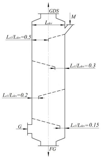
Figure 1.
Multistage shelf device circuit: M—raw material; G—gas; GDS—gas-dispersed substance; FG—finished granules.
Shelf contact elements differ from gas distribution grids of fluidized-bed devices and wedge-shaped elements plates primarily due to the presence of outloading space between the end of the shelf and the wall in the unit (Figure 1). The width of the outloading space is expressed by the ratio Lcl/Ldev, where Lcl is the distance between the end of the shelf and the wall of the device, and Ldev is the length of the side section of the device. It is possible to influence the gas flow distribution between the outloading space and the holes of the shelf, as well as on the ascending flow velocities in the separation space and the solid phase, moving along the shelf, by varying the Lcl/Ldev ratio, the perforation degree of the shelf ψ. The tilt angle of the shelf γ to a lesser extent affects the velocities profile of the gas flows over the outloading space and the holes of the shelf. The optimal tilt angle of the shelves is γ = 25° to the horizontal plane (Figure 2). The material particles lay on the surface of the shelf at a smaller angle. The particles quickly roll down to the outloading space and do not form a weighted layer above the shelf at a larger angle. The distance between the end of the upper shelf and the beginning of the lower shelf Ls is determined by the ratio between this distance to the length of the lateral part of the section in the device—Ls/Ldev. If Ls/Ldev < 0.5, the gas flow velocity in the outloading space increases. As a result, the free flow of material particles is impeded through the outloading space to the lower shelf. As the distance Ls increases, the gas flow velocity in the outloading space naturally decreases. When Ls = Ldev the flow rate is constant. Therefore, we take 0.5 < Ls/Ldev ≤ 1 in the construction of the device.
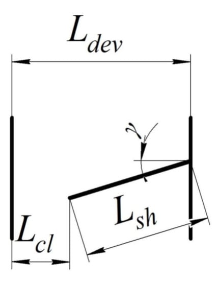
Figure 2.
The basic elements of the shelf device construction.
A polydisperse granular superphosphate mixture in the form of a 0.1–5 mm granule with a shape factor of 0.85 was used in the studies. The sieve analysis using wire sieves with aperture sizes (the size of the square hole side) 0.5, 1.0, 1.6, and 2.5 mm defined the granulometric composition of the polydisperse mixture. The sieves were folded in a vertical block with decreasing hole sizes from top to bottom and installed on a vibrating table with a control unit. Sieve analysis was carried out for 15–20 min, corresponding to the measurement accuracy [46]. Several samples were analyzed according to the methodology to assess the accuracy of the measurement [47]. The deviation of the results for each sample did not exceed 1.5–2.0%. The results of the sieve analysis of the initial polydisperse mixture are as follows: +2.5 mm—10%; 2.5 + 1.6 mm—25%; 1.6 + 1 mm—25%; 1 + 0.5 mm—20%; 0.5 mm—20%. According to the reference data, the true and bulk density of superphosphate granules obtained by the nodulizing method in a drum granulator was 2250 kg/m3 and 1100–1200 kg/m3 [48].
The laboratory unit consisted of a device equipped with a loading hopper with a belt feeder and an unloading hopper, a centrifugal cyclone to capture fine fractions with an unloading hopper, a high-pressure fan for pumping air through the device, and a cyclone. The walls in the device from the front side were transparent for visual observation and filming.
The initial mixture of the granulated superphosphate with amount of 3 kg was weighed on an electronic scale with an accuracy of 0.1 g. The mixture was heated to 90–95 °C in the loading hopper with electric heating elements (it corresponds to the temperature at the outlet of the drum granulator dryer [49]) and fed by the belt feeder into the device on the upper shelf. The moisture content of the granules was less than 1 wt% at this temperature, not affecting the heat transfer process [50]. The specific productivity of the raw material was 6–10 kg/(m2∙s). Air was sucked through the device by a high-pressure fan. The air flow was regulated and measured by a calibrated collector with a control valve. The air temperature at the inlet to the device was equal to the temperature in the laboratory: in summer conditions—22–27 °C; in winter conditions—18–22 °C. The material cooled to a temperature of 40–45 °C, was accumulated in the unloading hopper and unloaded at the end of the experiment. A small fraction of the material was trapped in the cyclone by the ascending air flow. When the device operated in a stationary mode (it was installed 15–20 s after turning on the feeder), 5–6 were selected from the unloading hopper and after the cyclone. The unloading hoppers were doubled to eliminate air leaks during material sampling. Spring-loaded valves were installed in the lower hopper. Then, the samples were weighed on an electronic scale with an accuracy of 0.1 g. For sieve analysis, the arithmetic mean value was taken from the weights of the selected samples. Several samples taken during repeated experiments under the same conditions were analyzed to assess the accuracy of the performed measurements. The deviation of the measurement results for each fraction between the selected samples was 1.5–2.0%. There were six experiments to eliminate the influence of random factors on the reliability of the measurement results.
The research regarding the features of one- and two-phase flows motion hydrodynamics in a shelf device was carried out with gas flow velocities of 1–5 m/s. A semiconducting thermoanemometer with an accuracy of 0.001 m/s measured the gas flow velocities in the workspace of the device. The measuring sensor was installed in the unloading space and the area above the shelf every 10 mm along the horizontal line. The measuring sensors were moved in height every 40 mm. There were four horizontal measurement lines above the shelf. The position of the thermoanemometer sensor was determined by the Xdev/Ldev ratio, where Xdev is the current distance from the initial plane (the left wall of the device) along the section length Ldev of the device.
An alcohol U-shaped manometer measured the pressure difference of the device. One tube of the manometer was connected to a point of the body under the lower shelf, and the second—at the gas outlet after the upper shelf. The measurement error when setting two levels (on each tube) was ±2 mm at an ambient temperature of 20 ± 5 °C.
One used filming under stroboscopic illumination at a frequency of 32 frames per second through the transparent walls of the device for establishing the mechanism and peculiarities of the gas-dispersed flow motion.
The research on the heat transfer peculiarities between the solid phase and the gas flow was carried out by cooling the superphosphate granules with an air flow. The temperature regime in the workspace of the device was controlled by thermocouples “Chromel-Copel” with open junctions through a self-recording potentiometer with an accuracy of 0.5 °C.
The thermocouple sensor was a protective metal case like a tube with a diameter of 1 mm and 60 mm long. There was a junction of interconnected chrome and copel thermoelectrodes 0.1 mm in diameter at the end of the tube. The heat capacity of this junction is negligible. It enables to perform measurements under conditions of continuously changing temperatures. Temperature sensors were installed at the following points: in the outside air supply pipe—to the device, in the loading hopper and unloading hoppers—after the device and the cyclone, in the separation space—at the outlet of the gas-dispersed flow from the device. The weighted layer temperature on the lower shelf was measured by placing three sensors along the entire length of the shelf at the height of up to 5–8 mm, one in the unloading space area and two at the gas flow outlet from the weighted layer.
The heat transfer coefficient was calculated from the basic equation of heat transfer, while the total surface area of the particles was estimated per unit volume of the layer. This approach is also confirmed in [51,52]. The velocities of solid particles in the layer are small compared to the gas flow rate. The ratio between the gas velocity in the free section of the device and the gas velocity between the particles in the layer varies over the section and height of the device. Therefore, it is advisable to consider the gas flow rate in the free section of the device when determining the Reynolds criterion.
As a criterion for assessing the cooling degree of the product in the cooler, a cooling coefficient was used, which is the ratio of the actually removed heat to the amount of heat that is removed when the material is completely cooled to the initial temperature of the cooling air:
where tgi, tgf, tai—respectively, the initial, final temperature of the granules, and the initial temperature of the cooling air, °C.
The efficiency of small particles separation from the weighted layer was characterized by the small fraction extraction degree into the ablation εм, representing the ratio of the small fraction size in the ablation to its amount in the raw material.
4. Research Methodology
The total aerodynamic resistance ΔP is defined as a set of resistances of the degrees in the shelf device (pressure loss on the shelf) Δpi [53]:
The aerodynamic resistance of each shelf contact depends on the nature of the gas flow interaction with the shelves, installed at a certain angle, the shelf perforation degree ψ, the dispersed material amount in the inter-shelf space, characterized by the layer porosity ε or the concentration of the solid particles in the workspace of the device β. One should note that the specified pressure drop in the holes will decrease along the shelf. Therefore, the efficiency of the perforation holes with the same diameter will also decrease approaching the outloading space.
The pressure loss for elementary jet moving along a perforated shelf can be considered as the sum of the losses along the shelf length with the current coordinate X and local loss through the perforation holes:
where —pressure loss along the shelf length with current coordinate, Pa (where λ—friction coefficient); de is the equivalent diameter of the shelf contact, m; [54]; Lsh is the shelf length, m; Bdev is the width of the device, m; Wgas is the cross section velocity of the gas flow, m/s; ρgas—gas flow density, kg/m3; —local loss in the perforation hole, Pa (where ξhol is the coefficient of the hole resistance); Whol—flow velocity in the perforation holes, m/s.
Thus, the total pressure loss between the control cross-sections consists of two components:
where
The nature of the gas flow jet lines along the shelf was experimentally confirmed [55]. It shows the parallel flow of two phenomena—the shelf bending and passing through its holes.
Air velocity in the perforation holes:
where φ is the velocity coefficient, which is 0.97–0.98 according to the experimental data [56]; z—specific pressure loss along the length, Pa/m.
The air flow loss through the holes of the shelf perforation is the following:
where ; ψ—degree of shelf perforation (free shelf cross-section); fsh—shelf area, m2.
In the outloading space Lcl (Figure 2) the pressure drop Δpcl will be minimal:
and the air flow loss is defined as
Total air flow rate is Vsh + Vcl. We will define the total air flow rates by integrating the ascending velocity function along the length of the perforated shelf and taking the constant perforation degree:
Substitution of the subintegral expression by a function , where enables to obtain the integration result within (0, Lsh):
The share of the flow through the outloading space is added to the balance equation of air flow rate along the cross-section of the shelf unit:
where —total air flow rate in the device.
The analysis of Equation (11) allows to calculate the gas flow velocity above the perforated shelf with the free cross-sectional area :
This ratio defines the pressure loss Δpi when installed in the workspace of one shelf device. It is possible to vary the constructive parameters of the shelf, namely its length and perforation degree. It is also possible to obtain profiles of the vertical velocities of the gas flow in the space above the shelf and the outloading space according to the algorithm below.
Comparing the total flow rates in the perforation holes to the flow rates calculated through the total area of the shelf , one can find the average velocity of the gas flow over the perforation holes in the vertical direction, taking into account Equation (6):
An analysis of this expression showed, first, that the local velocity of the gas flow above the holes in the vertical direction decreases linearly depending on the shelf perforation degree ψ and nonlinearly in the X direction along the shelf length to the outloading space (Figure 3).
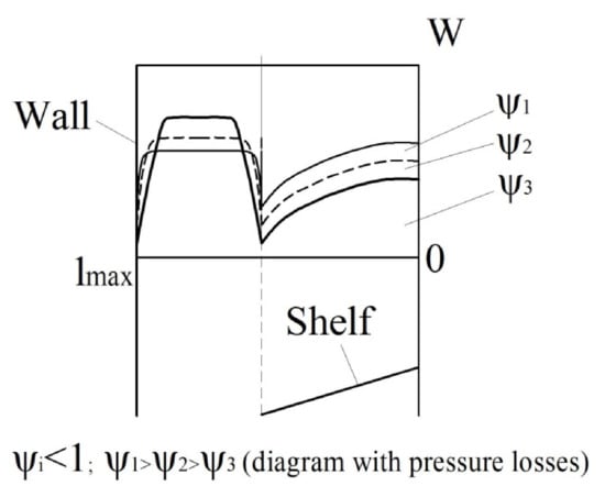
Figure 3.
Vertical velocity profiles over the shelf and in the outloading space, depending on the shelf perforation degree ψ (qualitative distribution).
5. Results and Discussion
5.1. The Influence of the Constructive Parameters of the Shelf on the Profile of Gas Flow Velocities
As a result of the free cross-section narrowing of the vertical channel, the inclined perforated shelf installation in the workspace of the shelf device causes a local increase in the velocity and turbulence of the gas flow in the outloading space and a change in the profile of gas flow velocities under the surface of the shelf and above it. As can be seen from Figure 4 (curves 1 and 2), a decrease in the value of the Lcl/Ldev ratio from 0.5 to 0.15 significantly increases the uneven distribution of the gas flow over the section of the workspace in the device in comparison with the installation of the perforated grid completely overlying the section of the workspace in the device (an analogue of the fluidized bed device (Figure 4, curve 4)), or the free channel (a pneumatic tube device (Figure 4, curve 5)). In this case, the width of the zone where the gas flow comes through the outloading space decreases, its absolute velocity and the profile of gas flow velocities in the workspace of the device is changed.
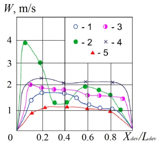
Figure 4.
The distribution of gas flow velocities along the section length of the device where the shelf is installed: 1—Lcl/Ldev = 0.5, ψ = 15%; 2—Lcl/Ldev = 0.15, ψ = 15%; 3—Lcl/Ldev = 0.15, ψ = 30%; 4—Lcl/Ldev = 0; 5—Lcl/Ldev = 1. Tilt angle of the shelf—γ = 25°. Gas flow velocity in the free cross-section—1.2 m/s.
If Lcl/Ldev = 0.5 and the degree of the shelf perforation is 15% (Figure 4, curve 1) in the above-shelf space, the absolute values of the gas flow velocities are practically constant over the section of this space and reach a maximum only in the outloading space and above it. If Lcl/Ldev = 0.15 (Figure 4, curve 2) the velocity profile has two maximum values: in the zone above the outloading space and at the middle level of the inclined shelf. This fact is explained by the differential “dividing” effect of the inclined shelf on the profile of gas flow velocities in or another one quantity through the outloading space and the holes in the inclined shelf. In the first case, the inclined shelf does not cause such a significant unevenness in the profile of gas flow velocities in the workspace of the device beyond its input point. In the second case, due to an increase in the resistance to the gas flow, caused by a sharp narrowing of the free cross-section in the device, significant swirlings arise at the inclined shelf edge. It defines the presence of a zone with a reduced gas flow velocity in the space above the end of the shelf. An increase in the perforation degree of the inclined shelf to 30% (Figure 4, curve 3) levels out the unevenness of the velocity profile over the cross-section of the workspace in the device since the gas flow is redistributed into the holes of the shelf due to a reduction of the hydraulic resistance of the shelf to its access.
A comparison of the experimental (Figure 4) and theoretical velocity profiles (Figure 3) shows a sufficient coincidence between the nature of the gas flow velocities change along the cross-section of the workspace in the device. The absolute value of the gas flow velocity in the outloading space with a decrease in the Lcl/Ldev ratio from 0.5 to 0.3 grows insignificantly for a shelf with a perforation degree from 0% to 30% (Figure 5).
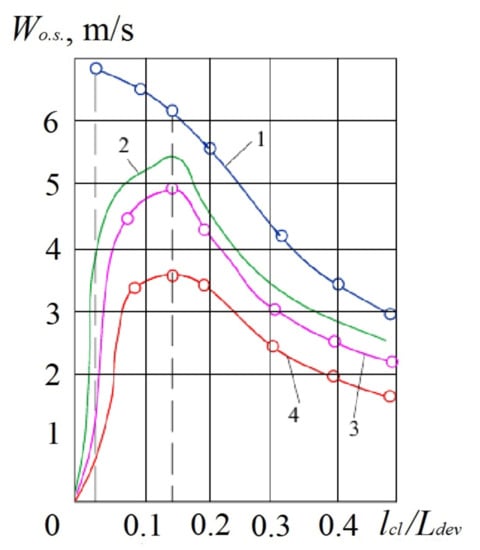
Figure 5.
The dependence of the gas flow velocity in the outloading space on the constructive parameters of the shelf. Shelf perforation degree ψ: 1–4—respectively, 0%, 5%, 15%, 30%. The tilt angle of the shelf—γ = 25°. Gas flow velocity in the free cross-section—1.65 m/s.
Under the conditions of the further decrease in the Lcl/Ldev ratio up to 0.15, the gas flow velocity in the outloading space increases by 2.5–3 times in comparison with the average gas flow velocity in the free cross-section of the device. With a decrease in the perforation degree of the shelf cross-section, this growth is more significant since the hydraulic resistance to the gas flow through the holes of the shelf contact is increased and the gas flow is redistributed towards the outloading space. The gas flow velocity in the outloading space reaches its maximum value at Lcl/Ldev = 0.15 for shelves with a perforation degree from 0% to 30%. If Lcl/Ldev < 0.15, the gas flow velocity in the outloading space decreases since the hydraulic resistance to the gas flow through the outloading space is increased so much that most of the flow passes through the holes of the shelf. If the shelf contact has a perforation degree of 0% (solid shelf), there is no redistribution, and the gas flow velocity in the outloading space continuously increases with reduction of Lcl/Ldev ratio (Figure 5, curve 1).
A change in the constructive parameters of the shelf has a significant effect on the uneven profile of gas flow velocities. It is reasonable to represent its quantitative measure by the dimensionless coefficient of the gas flow uneven distribution n, which is the ratio of the gas flow passing through the outloading space Vo.s. to its quantity in the holes of the shelf V (Figure 6).
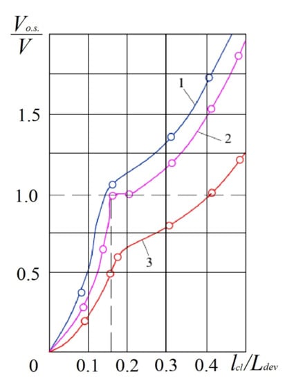
Figure 6.
The influence of the constructive parameters of the shelf on the uneven profile of gas flow velocities. Degree of the shelf perforation ψ: 1–3—respectively, 5%, 15%, 30%. The tilt angle of the shelf—γ = 25°. Gas flow velocity in the free cross-section—1.65 m/s.
If the coefficient of the gas flow uneven distribution is more than 1, the gas flow passes mainly through the outloading space, and if less than 1—through the holes of the inclined shelf. If the coefficient of the gas flow uneven distribution is 1, the flow is distributed in equal amounts both through the outloading space and through the holes of the shelf.
5.2. Hydrodynamic Modes for Weighing Solid Particles on a Shelf
The special nature of the gas flow distribution determines the conditions for the emergence of various hydrodynamic modes of interaction between solid particles in the material and the ascending gas flow. It enables widely to influence the heat treatment efficiency (for example, cooling and drying) of granular and grained materials in devices with inclined perforated shelves.
At low gas flow velocities, the material continuously fed into the device with a flow rate of 6 kg/(m2∙s) moves along the surface of the inclined shelf in the form of a rapidly “jumping” layer since the particles at the outlet of the supply pipe have sufficient inertia force. The porosity of such a layer reaches 0.8–0.85, and the concentration of material particles in it is 20–30 kg/m3 (0.15–0.2 m3/m3). Particles of the material after moving along the inclined shelf surface with a velocity of 0.2–0.3 m/s are inhibited at the device wall in the outloading space and are accumulated on the wall surface (Figure 7a).
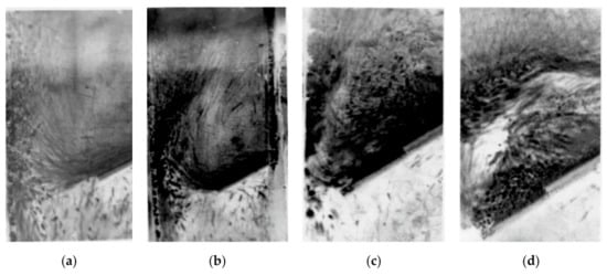
Figure 7.
Photographic image of hydrodynamic modes: (a) “gravitationally falling layer” mode; (b) “transitional” mode; (c) “weighted layer” mode; (d) “piston” mode.
The accumulated particles layer is blown by the ascending gas flow. Moreover, the layer mass due to the arrival of new portions of solid particles of material gradually increases. At a certain point in time, it exceeds the aerodynamic force of the ascending air flow, after which some of the particles are fallen down the device through the outloading space. In this nature of the motion of the material particles, both on the inclined shelf surface and the outloading space, the aerodynamic forces of the ascending flow do not provide sufficient resistance to the motion of the solid particles. The main part of the material moves in the form of a thin layer through the outloading space mainly by gravitational forces. Therefore, this nature of the motion of the solid particles in the material was called the “gravitationally falling layer” mode.
By increasing the gas flow velocity, its impact on the material layer grows. It begins to weigh particles both on the shelf contact surface and near the surface of the device wall in the outloading space (Figure 7b). In this case, the porosity of the material layer moving along the surface of the inclined shelf decreases to 0.7–0.75, and the concentration of solid particles of the material increases accordingly to 80–150 kg/m3 (0.25–0.3 m3/m3). This mode was called “transitional”.
If a certain velocity of the gas flow is reached, its effect on the material particles increases so much that their share in the upper part of the layer, breaks away from the wall surface. As a result of the breakaway of solid particles in the material, their concentration in this zone increases, the particles do not have time to get carried away by the gas flow to the upper part of the device and, losing their velocity, “fall” down onto the inclined shelf surface. Thus, a continuously circulating vortex layer of solid material particles is formed above the surface of the inclined shelf. Having reached a certain period, the formed circulating vortex layer of solid particles has a stationary state in its hydrodynamic structure and is characterized by a constant concentration of solid particles in the layer equal to 160–280 kg/m3 (0.32–0.35 m3/m3). The porosity of such a layer is 0.65–0.68, which corresponds to the porosity of fluidized systems. At the same time, the material moves along the inclined shelf surface in the form of a dense layer blown by the gas flow, and in the form of a weighted intensely circulating layer in the zone above the outloading space (Figure 7c). The velocity of material particles motion on the inclined shelf surface in this mode is reduced to 0.05–0.15 m/s.
The above mechanism demonstrates the transition of the hydrodynamic mode of the “gravitationally falling layer” of the material into the “weighted layer” mode given the “transition” mode. The velocity at which such a transition occurs is called the critical velocity of the initial weighing. The empirical dependence of the type defines the critical velocity of the initial weighing:
where Lcl is the distance between the end of the shelf and the wall of the device, m; Ldev is the length of the cross-section side in the device, m; ψ is the perforation degree of the shelf, %; Wcrit—critical velocity of the initial weighing, m/s; dp is the average diameter of particles being weighed, m; ν is the kinematic coefficient of the gas flow viscosity, m2/s; Reo.s.—Reynolds criterion in conditions of particle hovering in a gas flow; Reo.s. = Wo.s. dp/ν; Wo.s.—medium velocity in conditions of particle hovering, m/s.
The “piston” mode for weighing material particles occurs in the workspace of the device with a further increase in the air flow velocity (Figure 7d). This mode does not work. It is characterized by the maximum gas flow velocity.
5.3. Features of Interphase Heat Transfer in a Layer Weighted on a Shelf
The influence of the gas flow velocity on the interphase heat transfer process intensity is represented by the dependence Nu = f (Re) (Figure 8).
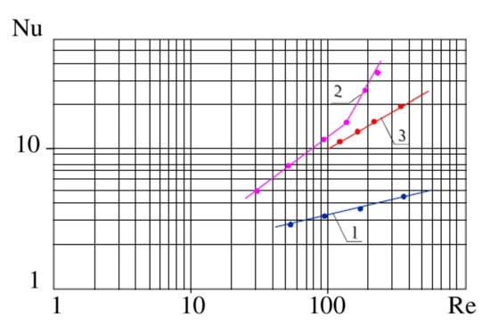
Figure 8.
The effect of gas flow velocity on the interphase heat transfer intensity: 1—“gravitationally falling layer” mode; 2—“weighted layer” mode; 3—the fluidized bed on a horizontal grid.
One can see from the graph (Figure 8, line 1) that the interphase heat transfer intensity between the gas flow and particles for the “gravitationally falling layer” mode increases slightly with an increase in the gas flow velocity in the free cross-section of the device, at 40 < Re < 600. It is proved by the fact that the particles of material coming from the loading nozzle move along the surface of the shelf with a sufficiently high velocity, the contact time of the particles with gas jets coming from the holes of the shelf is small. Owing to the insufficient contact time of the rapidly moving layer of material with the gas flow, the Nusselt criterion values obtained for the interphase heat transfer conditions on the inclined shelf surface under conditions of the “gravitationally falling layer” mode implementation in the workspace of the device come into the Nu < 5 area.
The empirical correlation for the “gravitationally falling layer” mode is the following [57]
where the Nusselt criterion Nu = α∙dp/λg; α—heat transfer coefficient from the surface of particles to the gas flow, W/(m2∙K); λg—gas heat (thermal) conductivity coefficient, W/(m∙K); Reynolds criterion Re = W∙dp/ν; W—gas flow velocity in the free cross-section, m/s.
Nu = 1.5 ∙ Re0.2 (if 40 < Re < 600),
The “weighted layer” mode initially (at Re = 30–170) is characterized by a gradual increase in heat transfer intensity, and then (at Re > 170) a significant increase in interphase heat transfer intensity is observed as a result of the material layer formation blown by the gas flow on the inclined shelf surface (Figure 8, line 2). This situation is explained by the improvement of the conditions for “washing” particles with a gas flow, “opening” of their surface, and also due to additional turbulization of the boundary film as a result of an increase in the relative velocity of neighboring particles. In the weighted material layer in the area above the outloading space, the active heat transfer surface increases due to intensively circulating material particles throughout the entire weighted layer space. In the weighted layer mode, the most intensifying effect is exerted by a gas jet entering the weighted layer of material through the outloading space at a sufficiently high velocity. Due to the expansion of the gas flow at the exit from the space of the outloading gap, intense interaction is ensured over the entire area of the weighted layer in the filtration mode. When the material is unloaded, the lower part of the weighted layer partially overlaps the outloading space. It causes a slight increase in the gas flow velocity in this zone and its part is redistributed into the holes of the shelf. In this case, the uniform filtration mode of the material layer by the gas flow is replaced by the gas jet “breakthrough” through the material weighted layer over the outloading space. Therefore, such a variable mode defines the pulsating nature of the material particles interaction with the gas flow, not only in the layer of material weighted over the outloading space, but also in the layer moving along the inclined shelf surface. It increases the phase contact intensity, and, accordingly, the heat transfer coefficient in the weighted layer mode in comparison with the fluidized bed (Figure 8, line 3).
The experimental studies enabled to identify the “active” heat exchange zone of the shelf unit—the outloading space zone.
The empirical correlation for the “weighted layer” mode is the following [57]:
Nu = 0.38 ∙ Re0.73 (if 30 < Re < 170),
Nu = 0.0045 ∙ Re1.73 (if 170 < Re < 300).
5.4. Estimation of the Residence Time of Solid Particles in the Overlayer Space
It is difficult to identify the true residence time of solid particles in the weighted layers with different structures. That is why the authors propose a calculation method for estimating the average residence time of particles in a layer weighted above a shelf.
As can be seen from the trajectories of solid-phase motion in the photographs (Figure 7), the weighted layer can be divided into two zones: the solid particle motion zone on the surface of the shelf and the particle motion zone in the overshelf space.
For the first zone, the residence time of the particles is calculated by the formula:
where up is the velocity of solid particles motion on the shelf surface, m/s; β—the volume concentration of the solid phase in the weighted layer, m3/m3; m—the experimental coefficient; m = 4.4–4.5—for the “weighted layer” mode; m = 10–10.2—for the “gravitationally falling layer” mode.
The following empirical correlation is proposed to find the volume concentration of the solid phase in the weighted layer:
where Gex is the mass flow rate concentration, kg/kg; Gex = Gp/Ggas; Gp—mass flow rate of the material, kg/s; Ggas—mass flow rate of gas, kg/s; W—velocity of the gas flow in free cross-section, m/s; Wo.s. is the velocity of medium diameter particles, m; n is the experimental coefficient; n = 0.25–0.35 for the “weighted layer” mode; n = 0.1–0.15—for the “gravitationally falling layer” mode.
There is no weighted layer in the space above the shelf for the “gravitationally falling layer” mode, as can be seen from the photograph (Figure 7a). Therefore, the second zone is typical only for the “weighted layer” mode (photograph, Figure 7c). When particles pass along the shelf length, they meet with a gas jet, formed by the outloading gap. Particles with a velocity less than the velocity of the gas jet are carried up into space above the shelf. The velocity of the gas jet decreases in height. The particles with a velocity greater than the velocity of the gas are lowered down to the shelf surface. Only small particles are carried out by the gas flow from the device. Thus, in the second zone, the particles move up the trajectory to the upper boundary of the weighted layer and downward trajectory to the surface of the shelf. Then the residence time of the particles is calculated as the following:
where Ltr is the length of the trajectory, m; ϑr is the pulsation velocity of the solid particle, m/s; k is the experimental coefficient; k = (1.5–3)∙Bdev.
The pulsation velocity of a solid particle in a weighted layer is determined by the empirical dependence:
where b is the experimental coefficient; b = 0.06 (defined according to the regression with correlation coefficient of 0.844).
The calculations show that for the “weighted layer” mode with a gas flow velocity of 2.4 m/s in a free cross-section, the velocity of particles with average diameter of 2 mm is 10–12 m/s, the flow mass concentration of 3 kg/kg, the volume concentration of solid phase in the weighted layer 0.34 m3/m3 and the particle velocity on the surface of the shelf is 0.1 m/s, the residence time of the particle for the first zone is τ1 = 5.73–5.97 s. For the second zone, at a pulsating velocity of particles in the layer of 0.14 m/s, the residence time is τ2 = 2 s. The total estimated residence time of the particles in the weighted layer τΣ = 7.73–7.97 s. The experimental residence time of the particles in the layer (calculated as the ratio of the material amount in the weighted layer to its mass flow rate) is τex = 7.72 s. For the gravitationally falling layer mode, the estimated time at a particle velocity of 0.25 m/s and a volume concentration of the solid phase in the layer above the shelf of 0.15 m3/m3 is τ1 = 1.12–1.15 s, and experimental τex = 1.16 s. The calculation results (Table 1) show that the residence time of the particles in the layer increases with the increase of the solid phase volume concentration in the layer and the number of shelves.

Table 1.
The residence time of solid particles in a shelf unit.
5.5. Practical Implementation
According to the comparative tests (Table 2) the shelf cooler-pneumoclassifier in terms of the cooling coefficient and the small fraction extraction degree exceeds pneumatic tubes devices, and units with fluidized and weighted layers, in which the specific cooling air flow rate to achieve the same cooling efficiency is 30–50% higher.
Table 2.
Test results of a shelf cooler.
The temperature of the material in the device with one shelf (if Lcl/Ldev = 0.5) decreases from 90 to 65–70 °C. This insignificant cooling degree is explained by the short residence time of the material moving along the inclined shelf in the gravitationally falling layer mode. At the same time, as a result of the small concentration of material particles in the workspace of the device and the close contact of the particles with the air jet, a small fraction is intensively extracted from the product. The highest dusting degree is achieved with the shelf perforation degree of ψ = 5%. If the air flow velocity in the free cross-section of the device increases from 2.4 to 3.7 m/s, the extraction degree of the fraction of less than 1 mm in ablation is 30–60%, and the product fraction of 1–1.6 mm is not more than 1.5–2%.
The cooling degree of the material on the shelf with a perforation degree of 15% and Lcl/Ldev = 0.5 increases significantly and reaches a maximum. If the specified optimal design parameters and air flow velocity in the cross-section of the device is 2.4 m/s, the “weighted layer” mode is implemented on the shelf, in which the particles are cooled more effectively, reaching a final temperature of 40–45 °C. As a result of the longitudinal mixing effect in this mode, the extraction efficiency of the small fraction is reduced to 20%.
The advantage of the shelf cooler-pneumoclassifier is the possibility to separate and to cool wide fractional composition materials without clogging grids and at low hydraulic resistances not exceeding 1.5 kPa. Thanks to the pulsating outloading with the flow of the air share between the shelf perforation and the outloading gap and the intense phase contact in this space, a clear pneumatic classification is provided at high specific loads, reaching 15–20 kg/(m2∙s) significantly exceeding the specific loads of 0.1–1.5 kg/(m2∙s), at which fluidized bed coolers-separators work.
In the granular mineral fertilizer technology, cooling is used to stabilize the structure of the granules [58]. Thus, drum coolers are used, which reduce the temperature of NPK fertilizer granules from 60–80 to 30 °C [58]. The granules are also cooled using fluidized bed coolers [59]. A single-stage fluidized bed cooler for cooling doubled superphosphate provides cooling of granules from 85 to 40 °C with air at a temperature of 20 °C at a fluidization rate of 1.6 m/s, as well as cooling diammonitrofoska from 85 to 30 °C [60]. Therefore, according to the data in Table 2, the performance of the developed shelf cooler is fully confirmed.
Table 3 presents the testing results of the shelf dryers, which have significant advantages since the material is simultaneously separated and dried in such devices.
Table 3.
Testing results of the shelf dryer.
Thus, the content required in the dust-free product of a fraction of fewer than 100 μm in size equal to 1–2% is achieved for fine-grained potassium velocities at a flow velocity of 1.44 m/s, and coarse-grained 1.34 m/s. If the flow velocity is more than 1.5 m/s in the coarse-grained potassium chloride, a fine-dispersed fraction is practically absent. The ablation of the fine-dispersed fraction of the material into cyclones does not exceed 6.5–10.8%, and the content of a fraction of more than 100 μm in it is 3–5%. The indicated results were achieved with specific loads on the section of the device in the material equal to 10 kg/(m2⋅s), the hydraulic resistance of 700–1500 Pa, and specific gas flow velocity of 0.12–0.14 m3/kg. For fluidized bed dryers, the ablation of the fine-dispersed fraction up to 7% is ensured at a gas velocity of 1.8–2.3 m/s. In this case, the specific gas flow rate is 0.41–0.52 m3/kg, the hydraulic resistance is 1500–2500 Pa.
In the potassium chloride production technology, fluidized bed dryers provide drying of the product from an initial moisture content of 3–9% to a final moisture content of 0.1% [61]. Therefore, according to the data in Table 3, the developed shelf dryer’s performance is fully confirmed.
6. Uncertainty Analysis
To define the optimal number of experiments and the highest accuracy degree and reliability of the obtained results, as well as for the processing of these results, methods of mathematical statistics were used [62].
Two types of measurement errors—random and systematic—may occur during the experiment conducting [62].
A random error reduces the accuracy of experiment results. An analysis of this type of error is possible by using the root-mean-square deviation σ, calculated by the following equation:
where is the arithmetic mean value; is the single parameter value; n is the number of measurements.
The maximum possible error of a single measurement, Δ, was determined by the three sigma rule:
The bilateral confidence interval of the arithmetic mean value ε was determined by the following function [62], provided that this parameter is located in the confidence interval with the probability not less than 95%:
where t is the Student’s criterion [63].
The root-mean-square error of indirect measurements is calculated as:
where .
The accuracy of the obtained regression equations is determined by the least-squares method [64].
The systematic measurement error had an identical effect on all parameters that were controlled during the experiment. All measurement devices were calibrated by calibration instruments by comparing their accuracy with that declared in the technical documentation in order to exclude the above error. Connection between measurement devices and controllers was provided with a maximum error of processing signals within 1.5%.
Creation of graphical dependences was carried out by differential methods of mathematical analysis and integral calculus. Reliability of the obtained experimental results is due to application of time-tested methods in practice.
7. Conclusions
- Due to the creation of an active hydrodynamic mode to weigh solid particles in a layer, a multistage fluidized bed device with inclined perforated shelves provides efficiency to carry out heat-mass transfer processes.
- Changes in the constructive parameters of the inclined shelf (the width of the outloading space and the shelf perforation degree) identify the different nature of the gas flow distribution between the holes of the shelf and the outloading space.
- Various hydrodynamic modes during operation of the device were revealed: the “gravitationally falling layer” mode and the “weighted layer” mode. The first mode is effective in carrying out pneumatic classification processes, and the second—in cooling and drying of granular materials.
- The study of interphase heat transfer showed a higher intensity of heat transfer in the weighted layer on an inclined perforated shelf compared to a traditional fluidized bed on a horizontal gas distribution grid.
- The theoretical model enables to present the gas flow velocity profiles depending on the length and perforation degree of the shelf contact, as well as to estimate the residence time of material particles in the workspace of the device.
- Further research will point to develop the mathematical model of the weighted layer hydrodynamics on an inclined perforated shelf. The corresponding scientific and methodological approaches based on using artificial neural networks for parameter identification of the proposed mathematical model will be developed.
Author Contributions
M.Y. and A.A. were engaged in the conceptualization of the study of hydrodynamic and heat transfer properties during the operation of multistage gravitational fluidized bed devices with inclined perforated shelves. Resources provided by J.K. and J.B. M.Y. and N.A. developed a method of experimental research for the case of an apparatus with inclined perforated shelves. A.A. and N.A. developed a mathematical model of the gas flow distribution in the device’s working volume. The obtained experimental results were analyzed by M.Y. and R.O. Practical implementation was confirmed by the M.Y. Data supervision, initial drafting, and editing were done by M.Y., R.O. and A.A. J.K. and J.B. carried out general supervision. R.O. and J.K. administered the project. All authors have read and agreed to the published version of the manuscript.
Funding
This research work was supported by the Ministry of Science and Education of Ukraine under the project “Technological bases of multistage convective drying in small-sized devices with utilization and heat recovery units”, project No. 0120U100476 and the Cultural and Educational Grant Agency of the Slovak Republic (KEGA), project No. KEGA 002TnUAD-4/2019.
Conflicts of Interest
The authors declare no conflict of interest.
References
- Al Amin, I.; Biń, A. Application of the fluidized bed process for formulation of WG-type pesticide granules. Powder Technol. 1994, 79, 135–146. [Google Scholar] [CrossRef]
- Lipin, A.G.; Nebukin, V.O.; Lipin, A.A. Assessment of coverage degree during particulate material encapsulation in fluidized bed. Izv. Vyss. Uchebnykh Zaved. Khimiya Khimicheskaya Tekhnol. 2019, 62, 84–90. [Google Scholar] [CrossRef]
- Li, Z.; Kind, M.; Gruenewald, G. Modeling Fluid Dynamics and Growth Kinetics in Fluidized Bed Spray Granulation. J. Comput. Multiph. Flows 2010, 2, 235–248. [Google Scholar] [CrossRef]
- Ostroha, R.; Yukhymenko, M.; Yakushko, S.; Artyukhov, A.E. Investigation of the kinetic laws affecting the organic suspension granulation in the fluidized bed. East. Eur. J. Enterp. Technol. 2017, 4, 4–10. [Google Scholar] [CrossRef][Green Version]
- Pusapati, R.T.; Rao, T.V. Fluidized bed processing: A review. Indian J. Res. Pharm. Biotechnol. 2014, 2, 1360–1365. [Google Scholar]
- Kornienko, Y.; Hayday, S.; Liubeka, A.; Martynyuk, O. Kinetic laws of the process of obtaining complex humic-organic-mineral fertilizers in the fluidized bed granulator. Ukr. Food J. 2016, 5, 144–154. [Google Scholar]
- Si, C.; Wu, J.; Wang, Y.; Zhang, Y.; Shang, X. Drying of low-rank coals: A review of fluidized bed technologies. Dry. Technol. 2015, 33, 277–287. [Google Scholar] [CrossRef]
- Sizgek, E.; Sizgek, G.D. Drying Characteristic of Porous ceramic microspheres in a microwave heated fluidised bed. Chem. Eng. Technol. 2002, 25, 287–292. [Google Scholar] [CrossRef]
- Randel, E.; Schak, J.; Islam, A. Fluid-bed dryers: Static versus vibrating. GEA Process Eng. 2013, 1–7. Available online: https://www.powderbulk.com/enews/2013/whitepaper/GEA.pdf (accessed on 1 November 2020).
- Zhang, Y.; Zhao, Y.; Dong, L.; Duan, C.; Zhou, E.; Lu, J.; Zhang, B.; Yang, X. Flow pattern transition characteristics in vibrated gas-solid fluidized bed of Geldart B magnetite powder using pressure drop signals analysis. Powder Technol. 2018, 327, 358–367. [Google Scholar] [CrossRef]
- Zeilstra, C.; Van Der Hoef, M.A.; Kuipers, J.H. Experimental and numerical study of solids circulation in gas-vibro fluidized beds. Powder Technol. 2013, 248, 153–160. [Google Scholar] [CrossRef]
- Jin, H.; Zhang, J.; Zhang, B. The effect of vibration on bed voidage behaviors in fluidized beds with large particles. Braz. J. Chem. Eng. 2007, 24, 389–397. [Google Scholar] [CrossRef]
- Singh, R.I.; Ghule, K. Design, development, experimental and CFD analysis of a prototype fluidized bed stripper ash cooler. Appl. Therm. Eng. 2016, 107, 1077–1090. [Google Scholar] [CrossRef]
- Rogala, Z.; Kolasiński, P.; Gnutek, Z. Effect of operating conditions on performance of silica gel-water air-fluidised desiccant cooler. In Proceedings of the International Conference on Advances in Energy Systems and Environmental Engineering (ASEE), E3S Web of Conferences, EDP Sciences, Wrocław, Poland, 7 November 2017; p. 146. [Google Scholar]
- Rogala, Z.; Kolasiński, P.; Błasiak, P. The influence of operating parameters on adsorption/desorption characteristics and performance of the fluidised desiccant cooler. Energies 2018, 11, 1597. [Google Scholar] [CrossRef]
- Katz, V. Cooling of granules in vibrating, suspended bed: Engineering simulation. Mod. Mech. Eng. 2016, 6, 76–90. [Google Scholar] [CrossRef]
- Zhang, Y.M.; Lu, C.X.; Shi, M.X. A practical method to estimate the bed height of a fluidized bed of fine particles. Chem. Eng. Technol. 2008, 31, 1735–1742. [Google Scholar] [CrossRef]
- Hu, X.; Calo, J.M. Plastic particle separation via liquid-fluidized bed classification. AIChE J. 2006, 52, 1333–1342. [Google Scholar] [CrossRef]
- Azimi, E.; Karimipour, S.; Xu, Z.; Szymanski, J.; Gupta, R. Statistical analysis of coal beneficiation performance in a continuous air dense medium fluidized bed separator. Int. J. Coal Prep. Util. 2015, 37, 12–32. [Google Scholar] [CrossRef]
- He, J.; Zhao, Y.; Zhao, J.; Luo, Z.; Duan, C.; He, Y. Enhancing fluidization stability and improving separation performance of fine lignite with vibrated gas-solid fluidized bed. Can. J. Chem. Eng. 2015, 93, 1793–1801. [Google Scholar] [CrossRef]
- Zhou, E.; Fan, X.; Dong, L.; Zhao, Y.; Yang, X.; Duan, C.; Liu, Q. Process optimization for arsenic removal of fine coal in vibrated dense medium fluidized bed. Fuel 2018, 212, 566–575. [Google Scholar] [CrossRef]
- SSulaiman, S.A.; Miin, C.S.; Naz, M.Y.; Raghavan, V.R. Particle image velocimetry of a swirling fluidized bed at different blade angles. Chem. Eng. Technol. 2016, 39, 1151–1160. [Google Scholar] [CrossRef]
- Li, J.; Yao, X.; Liu, L.; Lu, C. Investigation on distribution of particles in inlet region of an FCC external catalyst cooler with different inlet structures. Powder Technol. 2020, 362, 267–277. [Google Scholar] [CrossRef]
- Yao, X.; Zhang, Y.; Lu, C.; Wen, D. CFD investigation of gas-solids flow in a new fluidized catalyst cooler. Powder Technol. 2016, 304, 108–119. [Google Scholar] [CrossRef]
- Amiri, Z.; Movahedirad, S.; Shirvani, M. Particles mixing induced by bubbles in a gas-solid fluidized bed. AIChE J. 2016, 62, 1430–1438. [Google Scholar] [CrossRef]
- Shrestha, S.; Kuang, S.; Yu, A.; Zhou, Z. Particle shape effect on bubble dynamics in central air jet pseudo-2D fluidized beds: A CFD-DEM study. Chem. Eng. Sci. 2019, 201, 448–466. [Google Scholar] [CrossRef]
- Shrestha, S.; Gan, J.; Zhou, Z. Micromechanical analysis of bubbles formed in fluidized beds operated with a continuous single jet. Powder Technol. 2019, 357, 398–407. [Google Scholar] [CrossRef]
- Sarbanha, A.A.; Movahedirad, S.; Ehsani, M. On the hydrodynamics of a pseudo two-dimensional two-zone gas-solid fluidized bed. Chem. Eng. J. 2018, 350, 971–981. [Google Scholar] [CrossRef]
- Bakshi, A.; Ghoniem, A.F.; Altantzis, C. Mixing dynamics in bubbling fluidized beds. AIChE J. 2017, 63, 4316–4328. [Google Scholar] [CrossRef]
- Poós, T.; Szabó, V. Volumetric heat transfer coefficient in fluidized-bed dryers. Chem. Eng. Technol. 2018, 41, 628–636. [Google Scholar] [CrossRef]
- Yao, X.; Zhang, Y.; Lu, C.; Han, X. Investigation of the heat transfer intensification mechanism for a new fluidized catalyst cooler. AIChE J. 2015, 61, 2415–2427. [Google Scholar] [CrossRef]
- Zhang, Y.; Wei, Q. CPFD simulation of bed-to-wall heat transfer in a gas-solids bubbling fluidized bed with an immersed vertical tube. Chem. Eng. Process. Process Intensif. 2017, 116, 17–28. [Google Scholar] [CrossRef]
- Taofeeq, H.; Al-Dahhan, M. Heat transfer and hydrodynamics in a gas-solid fluidized bed with vertical immersed internals. Int. J. Heat Mass Transf. 2018, 122, 229–251. [Google Scholar] [CrossRef]
- Hofer, G.; Schöny, G.; Pröll, T. Acting on hydrodynamics to improve the local bed-to-wall heat transfer in bubbling fluidized beds. Chem. Eng. Res. Des. 2018, 134, 309–318. [Google Scholar] [CrossRef]
- Yang, L.; Zhan, W. New concept for ADS spallation target: Gravity-driven dense granular flow target. Sci. China Ser. E Technol. Sci. 2015, 58, 1705–1711. [Google Scholar] [CrossRef]
- Lytvynenko, A.; Yukhymenko, M.; Pavlenko, I.; Pitel, J.; Mižáková, J.; Ostroha, R.; Bocko, J. Ensuring the reliability of pneumatic classification process for granular material in a rhomb-shaped apparatus. Appl. Sci. 2019, 9, 1604. [Google Scholar] [CrossRef]
- Grbavčić, Ž.B.; Garić-Grulović, R.; Arsenijević, Z.L. Prediction of the choking velocity and voidage in vertical pneumatic conveying of coarse particles. Powder Technol. 2006, 161, 1–9. [Google Scholar] [CrossRef]
- Artyukhov, A.; Artyukhova, N.; Ivaniia, A. Creation of software for constructive calculation of devices with active hydrodynamics. In Proceedings of the 2018 14th International Conference on Advanced Trends in Radioelecrtronics, Telecommunications and Computer Engineering (TCSET), Institute of Electrical and Electronics Engineers (IEEE), Slavske, Ukraine, 20–24 February 2018; pp. 139–142. [Google Scholar]
- Artyukhov, A.E.; Sklabinskyi, V. Theoretical Analysis of Granules Movement Hydrodynamics in the Vortex Granulators of Ammonium Nitrate and Carbamide Production. Chem. Chem. Technol. 2015, 9, 175–180. [Google Scholar] [CrossRef]
- Artyukhov, A.; Obodiak, V.; Boiko, P.; Rossi, P. Computer modeling of hydrodynamic and heat-mass transfer processes in the vortex type granulation devices. CEUR Workshop Proc. 2017, 1844, 33–47. [Google Scholar]
- Artyukhov, A.E.; Sklabinskiy, V.I. Investigation of the temperature field of coolant in the installations for obtaining 3D nanostructured porous surface layer on the granules of ammonium nitrate. J. Nano Electron. Phys. 2017, 9, 1015. [Google Scholar] [CrossRef]
- Artyukhov, A.E.; Sklabinskyi, V.I. Experimental and industrial implementation of porous ammonium nitrate producing process in vortex granulators. Hayкoвий вiсник HГУ 2013, 6, 42–48. [Google Scholar]
- Yukhymenko, M.; Ostroha, R.O.; Artyukhov, A.E. Hydrodynamic and kinetic processes of the mineral fertilizer granules encapsulating in the multistage device with suspended layer. East.-Eur. J. Enterp. Technol. 2016, 6, 22–28. [Google Scholar] [CrossRef]
- Yukhymenko, M.; Ostroha, R.; Lytvynenko, A.; Mikhajlovskiy, Y.; Bocko, J. Cooling process intensification for granular mineral fertilizers in a multistage fluidized bed device. Adv. Manuf. Process. 2020, 2, 249–257. [Google Scholar] [CrossRef]
- Yukhymenko, M.; Ostroha, R.; Litvinenko, A.; Bocko, J. Estimation of gas flow dustiness in the main pipelines of booster compressor stations. IOP Conf. Ser. Mater. Sci. Eng. 2017, 233, 012026. [Google Scholar] [CrossRef]
- Malewski, J. On accuracy of sieve analysis. In Proceedings of the Annual Conference on Aggregates KruszMin’17, Wroclaw, Poland, 10–12 April 2017; pp. 103–111. [Google Scholar]
- Retsch GmbH Haan. Sieve analysis. In Taking a Close Look at Quality; Retsch GmbH Haan: Haan, Germany, 2009; 52p. [Google Scholar]
- Green, D.W.; Southard, Z.M. Perry’s Chemical Engineers’ Handbook, 9th ed.; McGraw Hill Professional: New York, NY, USA, 2018; 2352p. [Google Scholar]
- Yukhimenko, N.; Vakal, S. The exergy analysis of energy efficiency of the technology of granulated phosphorus-potassium fertilizers. East.-Eur. J. Enterp. Technol. 2016, 5, 4–10. [Google Scholar] [CrossRef]
- Luikov, A. Analytical Heat Diffusion Theory; Academic Press: New York, NY, USA, 1968; 685p. [Google Scholar]
- Wang, S.; Xu, C.; Liu, W.; Liu, Z. Numerical Study on Heat Transfer Performance in Packed Bed. Energies 2019, 12, 414. [Google Scholar] [CrossRef]
- Messai, S.; El Ganaoui, M.; Sghaier, J.; Belghith, A. Experimental study of the convective heat transfer coefficient in a packed bed at low Reynolds numbers. Therm. Sci. 2014, 18, 443–450. [Google Scholar] [CrossRef]
- Schulz, H. Hydrodynamics—Concepts and Experiments; InTech: Nappanee, IN, USA, 2015. [Google Scholar]
- Moran, S. How to do hydraulic calculations. In An Applied Guide to Process and Plant Design; Elsevier: Amsterdam, The Netherlands, 2015; pp. 115–126. [Google Scholar]
- Artyukhova, N.; Yuhimenko, M.; Shandyba, O.; Artyukhov, A. Simulation of the particle motion in devices with vertical sectioning of workspace. Ukr. Food J. 2014, 3, 446–453. [Google Scholar]
- Gupta, S.C. Fluid Mechanics and Hydraulic Machines; Pearson Education: Karnataka, India, 2006. [Google Scholar]
- Yukhymenko, M. Kinetics of the Heat Exchange and Reduction of the Energy Consumption during the Convection Cooling Process of the Granular Material; Bulletin Sumy National Agrarian University: Kyiv, Ukraine, 2001; Volume 7, pp. 119–124. [Google Scholar]
- Erro, J.; Urrutia, O.; Baigorri, R.; Fuentes, M.; Zamarreño, A.M.; Garcia-Mina, J.M. Incorporation of humic-derived active molecules into compound NPK granulated fertilizers: Main technical difficulties and potential solutions. Chem. Biol. Technol. Agric. 2016, 3, 2–15. [Google Scholar] [CrossRef]
- Lee, R.G.; Kpytowski, J.A. Fertilizer Manual. United Nations Industrial Development Organization (UNIDO) and International Fertilizer Development Center (IFDC); Kluwer Academic Publishers: Dordrecht, The Netherlands, 1998; 615p. [Google Scholar]
- Kryukov, G.V.; Tereshchenkov, V.V.; Lykov, M.V.; Gabeskiriya, O.V. Calculations foe single-stage fluidized-bed equipment for cooling mineral fertilizers. Chem. Pet. Eng. 1976, 12, 141–144. [Google Scholar] [CrossRef]
- Miranda, R.C.; Neto, J.F.G.; Aguiar, B.B.A.; Martins, M.; Silva, C.L.S. Model predictive control of potassium chloride drying by fluidized bed dryer. IFAC Proc. 2013, 46, 76–80. [Google Scholar] [CrossRef]
- Sahoo, P. Probability and Mathematical Statistics; University of Louisville: Louisville, KY, USA, 2013; 712p. [Google Scholar]
- Shao, J. Mathematical Statistics; Springer: New York, NY, USA, 2003; 592p. [Google Scholar] [CrossRef]
- Rice, J.A. Mathematical Statistics and Data Analysis; Thomson Brooks Cole: Duxbury, MA, USA, 2010. [Google Scholar]
Publisher’s Note: MDPI stays neutral with regard to jurisdictional claims in published maps and institutional affiliations. |
© 2021 by the authors. Licensee MDPI, Basel, Switzerland. This article is an open access article distributed under the terms and conditions of the Creative Commons Attribution (CC BY) license (http://creativecommons.org/licenses/by/4.0/).