Article

Design and Implementation of a Real Time Control System for a 2DOF Robot Based on Recurrent High Order Neural Network Using a Hardware in the Loop Architecture

by
Ulises Davalos-Guzman
1,
Carlos E. Castañeda
1,
Lina Maria Aguilar-Lobo
2,* and
Gilberto Ochoa-Ruiz
3
1
Centro Universitario de los Lagos, Universidad de Guadalajara, Lagos de Moreno 47460, Mexico
2
Departamento de Computación e Industrial, Universidad Autónoma de Guadalajara, Zapopan 45129, Mexico
3
School of Engineering and Sciences, Tecnologico de Monterrey, Zapopan 45201, Mexico
*
Author to whom correspondence should be addressed.
Appl. Sci. 2021, 11(3), 1154; https://doi.org/10.3390/app11031154
Submission received: 23 October 2020 / Revised: 22 November 2020 / Accepted: 25 November 2020 / Published: 27 January 2021
(This article belongs to the Special Issue Swarm Robotics 2020)

Abstract

:
In this paper, a real-time implementation of a sliding-mode control (SMC) in a hardware-in-loop architecture is presented for a robot with two degrees of freedom (2DOF). It is based on a discrete-time recurrent neural identification method, as well as the high performance obtained from the advantages of this architecture. The identification process uses a discrete-time recurrent high-order neural network (RHONN) trained with a modified extended Kalman filter (EKF) algorithm. This is a method for calculating the covariance matrices in the EKF algorithm, using a dynamic model with the associated and measurement noises, and it increases the performance of the proposed methodology. On the other hand, the decentralized discrete-time SMC technique is used to minimize the motion error. A Virtex 7 field programmable gate array (FPGA) is configured based on a hardware-in-loop real-time implementation to validate the proposed controller. A series of several experiments demonstrates the robustness of the algorithm, as well as its immunity to noise and the inherent robustness to external perturbation, as are typically found in the input reference signals of a 2DOF manipulator robot.

1. Introduction

In many current medical applications, the utilization of manipulator robots plays a very important role in dedicated procedures that require high accuracy and high performance in real time. Medical robots have been used in neurosurgery, orthopedics, and urology, and in these fields the robotic systems have been developed for minimally invasive interventions. Medical robotic systems are typically mechanical manipulators with rigid links connected by joints that allow relative motion from one link to another [1]. For example, a robotic enhanced device has been used in limb rehabilitation, which could replace (or partially relieve) physiotherapists [2], and authors in [3] reported the use of a manipulator robot for percutaneous ultrasound-guided therapy.
The systems typically used for these procedures are robots with two degrees of freedom (2DOF). However, 2DOF systems are highly nonlinear, with strong interconnections and dynamic behaviors. Robot manipulators are examples of nonlinear complex dynamics with strong interconnections, parameters and dynamics that are difficult to measure and to model [4]. One of the non-linearities can be present when the motor rotor is positioned anywhere in the dead zone for the equilibrium position. If the frictional torque exceeds the torque applied by the motor windings, the rotor will not move. Other non-linearity can be an asynchronous generator introduced in the system due to actuator saturation [5]. For the mentioned reasons, the neural networks (NNs) are selected to avoid these kinds of difficulties in the identification process.
Due to these facts, there is a need to design custom controllers to improve the accuracy and stability required in medical applications. A typical control scheme for 2DOF systems is composed of two processes: an identification model that approximates the model of the system, and a control algorithm.
In the identification process, the behavior of the 2DOF system is approximated using a nonlinear function. However, due to its complex dynamics, is very important to consider several aspects to obtain a good approximation of the identification model. Two important factors are the viscous friction in the joints of the robot, and the inertia and the gravity of the 2DOF system in continuous time [6] or in discrete time [7]. In this context, recently neural network algorithms have gained popularity to identify complex dynamics systems, due to their learning capabilities and inherent adaptability. An example of this approach is presented in [8], which used a decentralized neural identification in discrete time, trained with an extended Kalman filter (EKF) with static covariance matrices. An adaptive tracking controller based on a recurrent neural identifier was used in [9]. A fully connected neural network was used to identify a time-varying delayed nonlinear dynamic system in [10]. Another identification model that uses a fuzzy cerebellar model articulation controller with a neural network on continuous time was reported in [11]. In [12] a modified EKF algorithm, where the associated state and measurement noise covariance matrices are composed by the coupled variance between the plant states, is presented.
On the other hand, the sliding-mode control (SMC) technique has been used as a controller to ensure high accuracy, given that it provides a high insensitivity to parameter variations, representing a powerful yet simple implementation and allowing the operation of the switched-mode power converters. The potential of SMC was first demonstrated in [13]; moreover, SMC was validated in [14], where a robust control scheme based on the discrete-time block feedback linearization technique combined with SMC was presented.
In recent work, an identification algorithm similar to the EKF algorithm was used to approximate the dynamics in discrete time, with a 2DOF manipulator robot. In [4] a robot dynamics is analyzed for a 2DOF manipulator robot using an unscented Kalman filter in a parallel series configuration as the learning algorithm. In this it was not necessary to know the parameters of the plant or external disturbances. Another investigation showing a different method to examine a non-singular fast time sliding mode controller (NFTSM) is in [15] where a wavelet neural network (WNN) was used. The inputs were approximations of the upper limits of uncertainties and disturbances, to mitigate the effect of uncertainties taking into account approximation errors and unknown uncertainties. Thus, it can be concluded that achieve a high tracking precision, reducing the vibration phenomenon and also a quick response against errors and uncertainties.
In [16], simulation and experimental work involving a 3DOF robot manipulator was controlled using a back propagation neural network (BPNN) in discrete time given a normalized opening ratio of the joints. The Artificial Neural Network (ANN) output was the control voltages applied to motors mounted in the 3DOF.
As a different way to approximate and control the dynamics involved in a 2DOF Robot, the novel control architecture presented in [17] employs an adaptative neural network using proportional derivative control comparison plus a feedforward fuzzy controller, where the NN is pre-trained in simulation several times to obtain a suitable values of weights to avoid overshoots in the torque being applied to every joint. Another method of controlling a non-linear system is the neuro-fuzzy controller for the position control arm used in [18], where a five layer neural network is used to adjust the input and output parameters of the membership function in a fuzzy logic controller, concluding that this proposed control is better than a proportional–integral–derivative (PID) controller for a robot trajectory.
Finally, in [5], a real-time implementation of a recurrent wavelet first-order neural network is presented. In the mentioned paper is proposed to achieve better identification of the dynamic behavior where a 2DOF robot manipulator is used for designing a centralized neural integrator back stepping control scheme.
In this paper, we propose a control scheme based on a decentralized recurrent high-order neural network (RHONN) in order to identify the dynamics of a 2DOF system in discrete time, coupled with the SMC technique. The RHONN is trained online using the modified EKF reported in [12]. This training algorithm ensures fast learning convergence of the identification error. The proposed control system includes the RHONN identification of the plant and the application of the SMC control technique, ensuring the stability and robustness of the system. The validation of the system is carried out in a hardware-in-loop architecture based on Xilinx System Generator (XSG) software [19], which enables the use of a Matlab/Simulink environment to create and verify hardware designs, using a Virtex 7 field programmable gate array (FPGA). The hardware-in-loop (HIL) simulation is used to test the controller system design to verify the response of the system in real time, due to virtual stimulus without the burden of sacrificing scarce programmable resources [20].
The main contributions can be highlighted as follows.
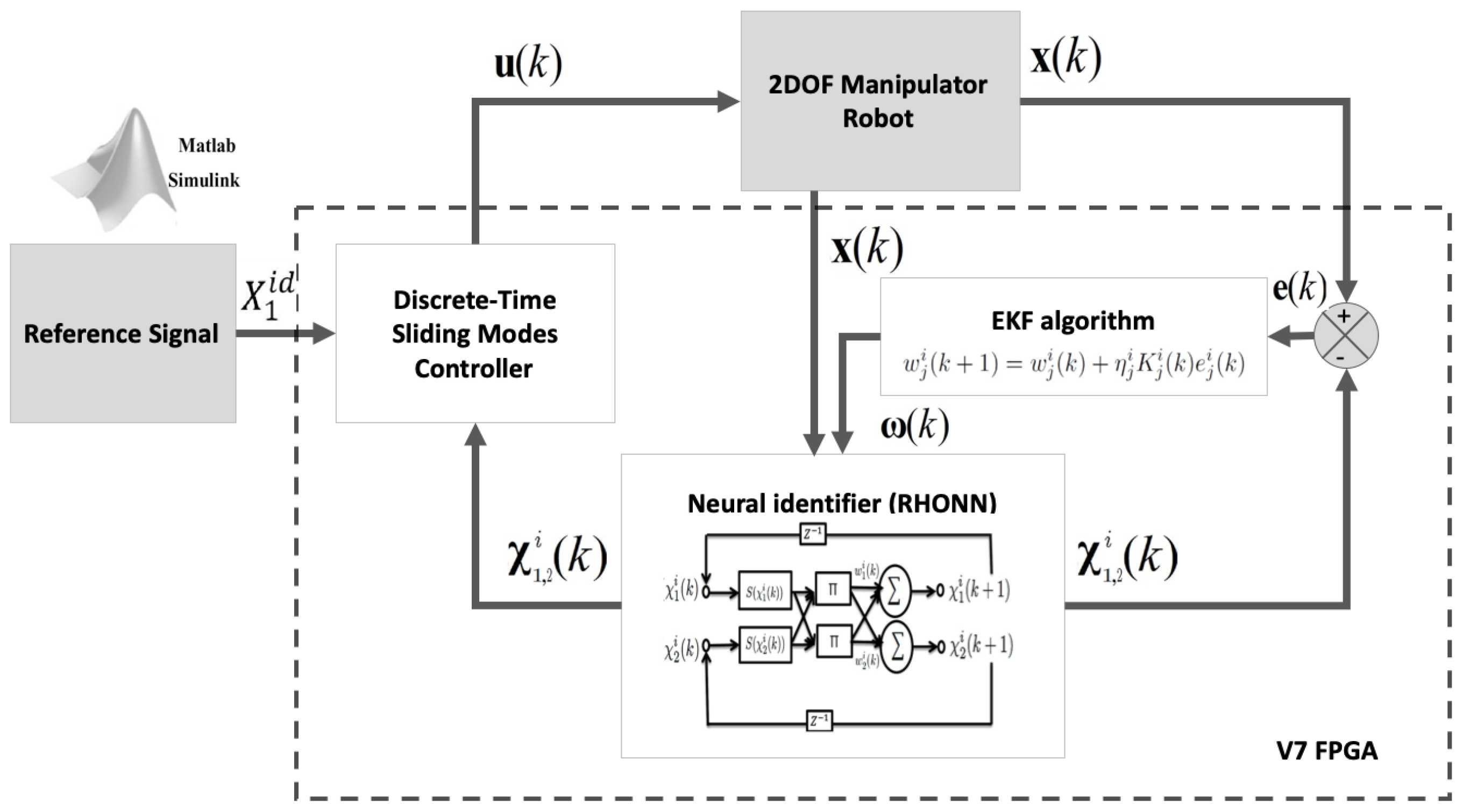
  • The control system design and implementation for a 2DOF manipulator robot using a RHONN in a hardware-in-loop architecture.
  • Is presented a methodology for identification and tracking of the 2DOF manipulator robot.
  • A Real Time implementation on an FPGA of the proposed control system based in a RHONN with an EKF algorithm with an SMC.
  • Inside the EKF the FPGA computes the associated state and measurement noise covariance matrices composed by the coupled variance between the plant states.
  • The results are obtained with a hardware-in-loop architecture and the experiments and the results show the high performance of the system.
Section 2 presents the discrete-time 2DOF robot manipulator model used and the rest of this paper is mainly divided into three parts. First, in Section 3, we present the control system architecture, and explain the neural identification method based on the RHONN, the extended Kalman filtering training algorithm and the discrete time sliding mode controller. Secondly, the design and implementation in real time based on hardware-in-loop architecture are presented in Section 4. Finally, in Section 5 we present the experimental tests with real-time results to validate the performance of the system in the identification process and the tracking control.

2. Discrete-Time 2DOF Robot Manipulator Model

The model of a 2DOF manipulator robot, presented in [21,22], is described using a second-order nonlinear differential equation:
M ( q ) q ¨ + C q , q ˙ q ˙ + g ( q ) + f q ˙ = τ ,
where q is the 2 × 1 vector of joint positions, q ˙ is the 2 × 1 vector of joint velocities, τ is the 2 × 1 vector of applied torques, M ( q ) is the 2 × 2 symmetric positive definite manipulator inertia matrix, C q , q ˙ is the 2 × 2 matrix of centripetal and Coriolis torques, and g ( q ) is the 2 × 1 vector of gravitational torques.
Then, the model in Equation (1) can be represented in state space as:
x 1 ˙ = x 2 x 2 ˙ = M 1 C x 2 + g ( x 1 ) + f x 2 + M 1 τ y = x 1 , ,
where x 1 = q 1 q 2 is the output of the system, x 2 = q ˙ 1 q ˙ 2 , M = M q , q ˙ R 2 , C = C q , q ˙ R 2 , g q 1 , q 2 R 2 × 1 , f q 1 ˙ , q 2 ˙ R 2 × 1 , and τ = τ 1 τ 2 is the torque vector as the input signal. Using the Euler method, the model in Equation (2) can be represented in discrete-time as:
x 1 ( k + 1 ) = x 1 ( k ) + T s x 2 ( k ) x 2 ( k + 1 ) = x 2 ( k ) T s M 1 [ C x 2 ( k ) + g ( x 1 ( k ) ) + f x 2 ( k ) ] + M 1 τ ( k ) y ( k ) = x 1 ( k ) ,
with x 1 ( 0 ) = 0 0 and x 2 ( 0 ) = 0 0 , where k Z 0 is the time index with Z as the set of non-negative numbers and T s is the sampling time. It must be noted that the Euler method represents a good alternative for the nonlinear discrete plant when the sampling rate is very low [23].

3. Discrete-Time 2DOF Robot Manipulator Model

In Figure 1, the proposed control system is presented. The structure has a neural identifier based in a RHONN trained with the EKF algorithm, and a discrete-time sliding mode controller. The system is validated on a FPGA hardware-in-loop implementation and Matlab/Simulink is used to model the 2DOF manipulator robot and the reference signal.

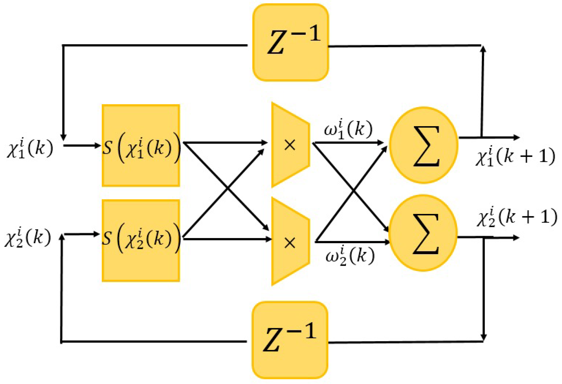
3.1. Neural Identification Method

The identification of the 2DOF model represented in the discrete-time model in Equation (3) is realized using a RHONN architecture [12]. The mathematical expression of the RHONN is described by the following Equation (4):
χ 1 l ( k + 1 ) = w 1 l ( k ) S ( χ 1 l ( k ) ) + w ¯ 1 l χ 2 l ( k ) χ 2 l ( k + 1 ) = w 2 l ( k ) S ( χ 1 l ( k ) ) + w 3 l ( k ) S ( χ 2 l ( k ) ) + w ¯ 2 l u l ( k ) y ( k ) = χ 1 l ( k ) ,
where χ is the neural network state, w 1 , w 2 and w 3 are the synaptic weights calculated online by the EKF algorithm, S ( · ) is the sigmoidal activation function, u ( k ) is the l-th input signal, k is the discrete time step, l-th are the states of the NN, and y is the output of the RHONN [12]. The RHONN architecture used to identify the 2DOF system model, described by Equation (4), is presented in Figure 2. The RHONN is composed of two neurons and one layer; the high order is due to the second-order multiplication between the two states of the system. The potential of this RHONN is centered in the EKF algorithm with the covariance matrix explained in Section 3.2.

3.2. Extended Kalman Filtering Training Algorithm

In previous research, we demonstrated that Kalman filtering (KF) estimates the state of a linear system with an additive state and output white noise [12]. However, as the neural network mapping is a nonlinear system, then it is necessary to use an extended-KF (EKF) algorithm as described in [24]. The EKF is used for non-stationary discrete systems to ensure the accuracy of the online training process, and the mentioned method is shown below.
w j l ( k + 1 ) = w j l ( k ) + η j l K j l ( k ) e j l ( k ) K j l ( k ) = P j l ( k ) H j l ( k ) M j l ( k ) P j l ( k + 1 ) = P j l ( k ) K j l ( k ) H j l ( k ) P j l ( k ) + Q j l ( k ) ,
with
M j l ( k ) = [ R j l ( k ) + H j l ( k ) P j l ( k ) H j l ( k ) ] 1 , e j l ( k ) = [ x j l ( k ) χ j l ( k ) ] ,
where l = 1 , 2 is the number of joints, j = 1 , 2 is the number of states of each joint, K j l ( k ) R L j l × m is the Kalman gain matrix, L j l is the respective number of neural network weights, χ j l ( k ) R m is the j-th neuron state corresponding to the l-th joint, x j l ( k ) R m is j-th plant state of the l-th joint, η j l is the learning parameter, w j l ( k ) R L j l is the synaptic weight vector calculated online; Q j l ( k ) R L j l × L j l is the measurement covariance matrix; R j l ( k ) R m × m is the state noise covariance matrix; e j l ( k ) is the prediction identification error; H j l ( k ) R L j l × m is a matrix in which each input H j l ( k ) is the derivative of j-th neural network state as is explained in more detail in [25]. For the proposed time-varying learning algorithm, the covariance matrices P j l ( k ) , Q j l ( k ) and R j l ( k ) are initialized as diagonal matrices with random entries, and Q j l ( k ) and R j l ( k ) are composed of a time-varying coupled covariance between the j-th plant state, which allows the identification of interactions associated to the plant states and helps with the neural convergence. This technique is proposed in [12] and requires the efficient computation of Q j l ( k ) and R j l ( k ) in time-varying form such that it minimizes the identification error:
m i n Q j l ( k ) x j l ( k ) χ j l ( k ) , m i n R j l ( k ) y j l ( k ) y ¯ j l ( k ) .
This can be done in such a way that minimizes the variance ( σ ):
σ ( x ( k ) ) = E x ( k ) x m ( k ) 2 1 / 2 , σ ( y ( k ) ) = E y ( k ) y m ( k ) 2 1 / 2 ,
where x m ( k ) = E x ( k ) and y m ( k ) = E y ( k ) are expressed in terms of the recursive expectation value, E , which represents the instantaneous mean value of the signal. For the proposed formulation, the state x 1 ( k ) x 2 ( k ) and output x 1 ( k ) = y ( k ) are considered as available measurements [14]. To get the best identification process, the algorithm calculates the prediction covariance matrices with a recurrent on-line feeding process.

3.3. Discrete-Time Sliding Mode Controller

For the present proposal, we assume that the RHONN of Equation (4) can be represented in general nonlinear discrete-time form as follows:
χ ( k + 1 ) = f ( χ ( k ) ) + B ( χ ( k ) ) u ( k ) + d ( k ) , y ( k ) = χ 1 ( k ) ,
where χ ( k ) R n is the state vector of the system (neural network state), u ( k ) R m is the input vector, y ( k ) R p is the output vector, the vector f ( · ) and the function B ( · ) are smooth vector fields, and d ( k ) is a vector that represents non-modeled dynamics and disturbances. This implies a non-singular transformation of the system in Equation (9), and can thus be represented in a controllable block form as in [26]. The r block is as follows:
χ i ( k + 1 ) = f i ( χ ¯ i ( k ) ) + B i ( χ ¯ i ( k ) ) χ i + 1 ( k ) + d i ( k ) χ r ( k + 1 ) = f r ( χ ( k ) ) + B r ( χ ( k ) ) u i ( k ) + d r ( k ) , y ( k ) = χ 1 ( k ) , with i = 1 , , r 1 ,
where χ ( k ) = [ χ 1 ( k ) χ i ( k ) χ r ( k ) ] , d ( k ) = [ d 1 ( k ) d i ( k ) d r ( k ) ] and χ ¯ i ( k ) = [ ( χ 1 ( k ) χ i ( k ) ] , and the sets of numbers ( n 1 , n 2 , n r ) , which define the structure of the system in Equation (10), and satisfy n 1 n 2 n r m [26].
Then, the transformation regarding the tracking error z ( k ) is defined as follows:
z 1 ( k ) = χ 1 ( k ) χ 1 d ( k ) = χ 1 ( k ) χ 1 d ( k ) + Δ 1 ( k ) , z i ( k ) = χ i ( k ) χ i d ( k ) = χ i ( k ) χ i d ( k ) + Δ i ( k ) ,
where Δ i ( k ) represents the identification error for the i-th joint block, and χ i d ( k ) is the desired value for χ i ( k ) obtained as follows:
χ 2 d ( k ) = B ˜ 1 + k 1 z 1 ( k ) f ˜ 1 χ 1 ( k ) , k , χ i + 1 d ( k ) = B ˜ i + k i z i ( k ) f ˜ i χ ˜ i ( k ) , k .
It is important to mention that for n 1 , n 2 , n r > 1 , B ˜ i + = B ˜ i B ˜ i B ˜ i 1 is a pseudo-inverse matrix and thus we can guarantee that B ˜ i is non-singular. For our particular case, B ˜ is a scalar ( ω ¯ 1 l ). Additionally, the fact that the K i diagonal matrix is made by k l elements, which constitutes a Schur matrix, means it yields the following expression:
f ˜ 1 χ 1 ( k ) , k = B ˜ 1 S 1 χ 1 ( k ) , k χ 1 d ( k + 1 ) , f ˜ i ( · ) = B ˜ i S i χ 1 ( k ) , , χ i ( k ) χ i 1 d ( k + 1 ) , i = 2 , , r .
Then, applying the procedure explained in [14], the transformations in Equations (11)–(13) reduce the system in Equation (4) to the following form:
z 1 l ( k + 1 ) = k 1 l z 1 l ( k ) + ω ¯ 1 l z 2 l ( k ) + Δ ˜ 1 l ( k ) z 2 l ( k + 1 ) = f ˜ 2 l χ ( k ) , k + ω ¯ 2 l u l ( k ) + Δ ˜ 2 l ( k ) ,
Then, if we apply the block control technique in the last block of system, Equation (14) yields
z 2 l ( k + 1 ) = k 1 l z 1 l ( k ) + Δ ˜ 1 l ( k ) ,
with the superscript l = 1 , 2 as the l-th joint, obtaining f ˜ 2 l χ ( k ) , k = ω 1 l ( k ) S χ 1 l ( k ) χ l d ( k + 1 ) . Each joint has two blocks ( r = 2 ), with n 1 = 1 and n 2 = 1 , Δ ˜ j l ( k ) = Δ j l ( k + 1 ) , and the subscript constitutes the j-th neural network state.
The sliding function s D l ( k ) can be derived from the block control transformation in Equation (11), and the last block of Equation (14) can be represented as
s D l ( k + 1 ) = ω 1 l ( k ) S χ 1 l ( k ) χ l d ( k + 1 ) + ω ¯ 2 l u l ( k ) + Δ ˜ 2 l ( k ) ,
Following the procedure explained in [14], the control law can be defined as
u l ( k ) = u ˜ e q l ( k ) for u ˜ e q l ( k ) u 0 l ( k ) u 0 l ( k ) u s l ( k ) u s l ( k ) for u ˜ e q l ( k ) > u 0 l ( k )
where u 0 l ( k ) represents the input signal (torques τ 1 ( k ) and τ 2 ( k ) of the system in Equation (3)), with
u ˜ e q l ( k ) = w ¯ 2 l 1 s l ( k ) + f ˜ 2 l ( χ l ( k ) , k ) u ˜ e q α ( k ) + w ¯ 2 l 1 f ˜ 2 l χ l ( k 1 ) , k 1 + u ˜ e q l ( k 1 ) u ˜ e q β ( k ) ,
and
u s l ( k ) = w ¯ 2 l 1 f ˜ 2 l χ l ( k ) , k .
In Equation (18), u ˜ e q α ( k ) belongs to the part that rejects the nonlinear dynamics of the RHONN in Equation (4), and u ˜ e q β ( k ) reduces the effect of the unknown identification error Δ ˜ j l ( k ) of Equation (14). The results of the closed-loop system are shown in the next section.
Now, following the procedure explained in [25]:
w ¯ 2 l u 0 l ( k ) > δ l , δ l = f 2 s l ( k ) + Δ ˜ 2 l ( k ) , f s l χ l ( k ) , k = χ r l k + χ r l d k + f ˜ r l χ l ( k ) , k ,
the control law in Equation (17) is able to drive the system in Equation (15) within a small neighborhood of the sliding manifold z 2 l ( k ) = 0 . Thus, the control error z 2 l ( k ) satisfies
z 2 l ( k ) = χ 2 l ( k ) χ 2 l d ( k ) O ( T s ) .
The sliding mode motion in an O ( T s ) boundary layer of z 2 l ( k ) = 0 is described by the first-order system:
z 1 l ( k + 1 ) = k 1 l z 1 l ( k ) + w ¯ 1 l z 2 l ( k ) + Δ ˜ 1 l ( k ) .
By direct inspection of Equation (22), there exists k 1 l such that k l > k 1 l , the position control error z 1 l ( k ) satisfies
z 1 l ( k ) δ 1 l , δ 1 l = 1 γ Δ ˜ 1 l ( k ) + O ( T s ) .
It is worth mentioning that the identification error Δ ˜ 1 l ( k ) can be made arbitrarily small by adding more higher order terms into the neural identifier in Equation (4), increasing the number of adjustable weights [12]. The 1 γ is a positive constant and must be modified to get a convergence of the sliding mode δ 1 l variable.

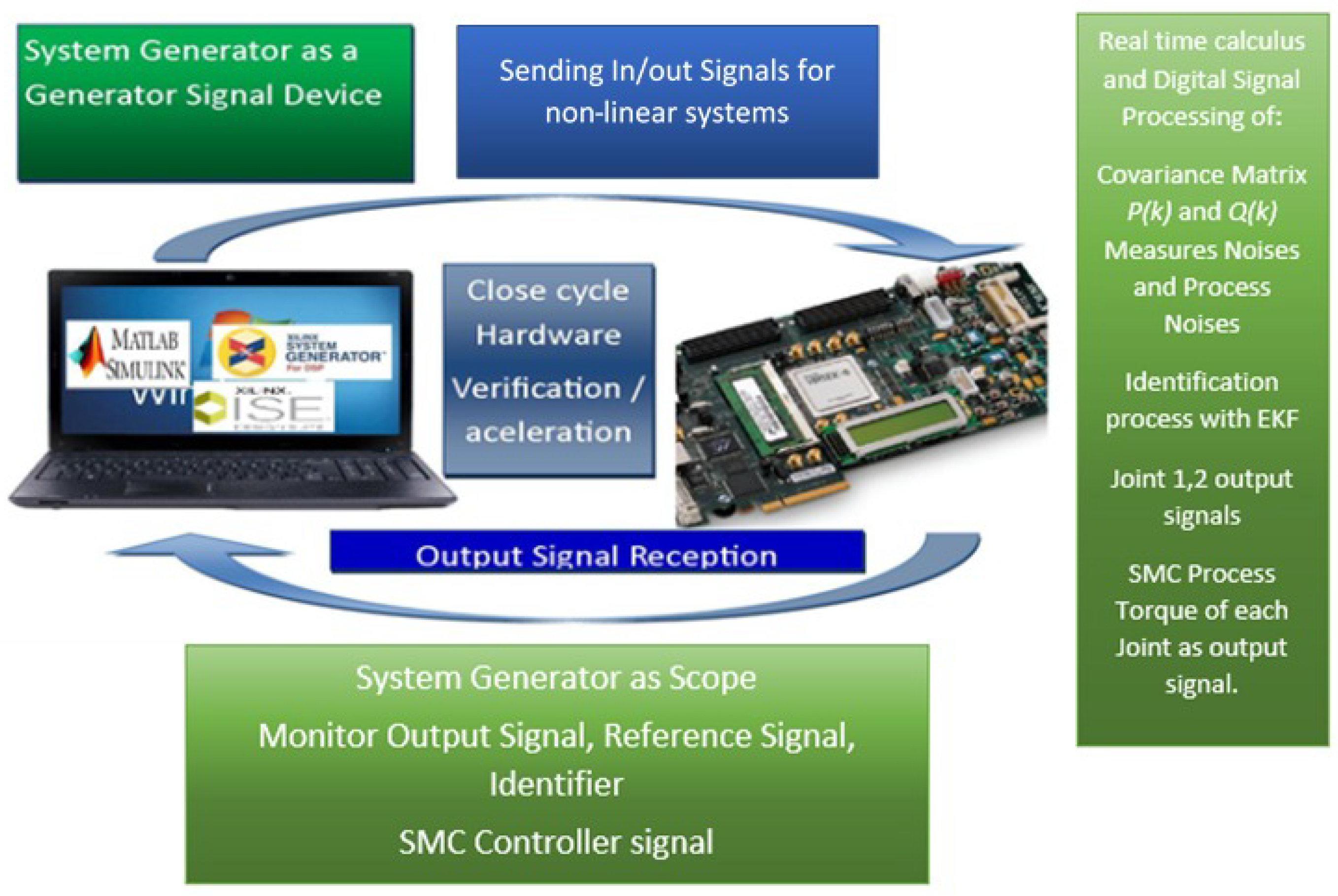
4. Real-Time Implementation and HIL Method

The real-time implementation of the proposed system is presented in Figure 3. The reference signal and the 2DOF manipulator robot model were realized in Matlab. The neural identifier based on the RHONN architecture, the EKF algorithm for the training, and the controller based on the discrete time sliding modes were implemented in a hardware-in-loop architecture using in the Evaluation Board Virtex 7 FPGA with an internal data acquisition device.
The testing of the system is performed with a virtual stimulus provided in HIL architecture so it gives an extraordinary opportunity to perform a real test case with a virtual stimulus, allowing the system to process the signals in real time and consequently obtain results in real time.
The nonlinear 2DOF manipulator robot is modeled in Matlab using the discrete-time presented in Section 2. The RHONN neural network is trained online using the EKF algorithm, where the associated state and measurement noise covariance matrices are composed by the coupled variance between the plant states. The implementation of the RHONN as the neural identifier was realized in the XSG design and the hardware-in-loop approach with a Virtex 7 FPGA. The results of the identification process and tracking control architecture was validated in a Matlab/Simulink environment and with the FPGA results. Figure 4 shows an image of the hardware-in-loop architecture.

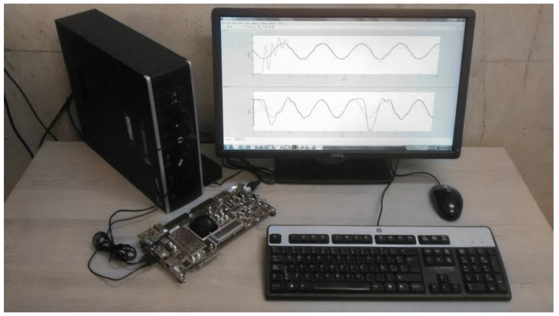
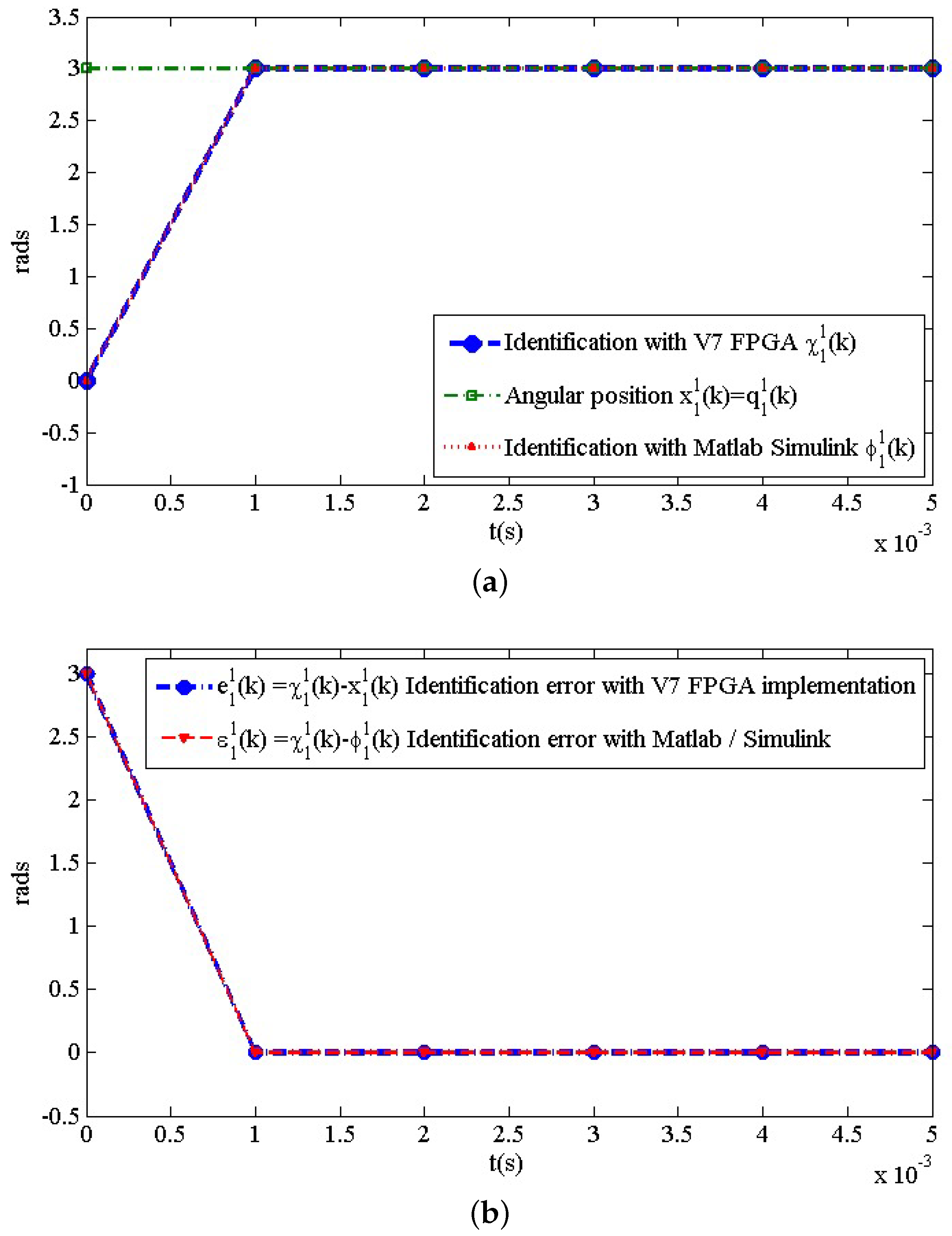
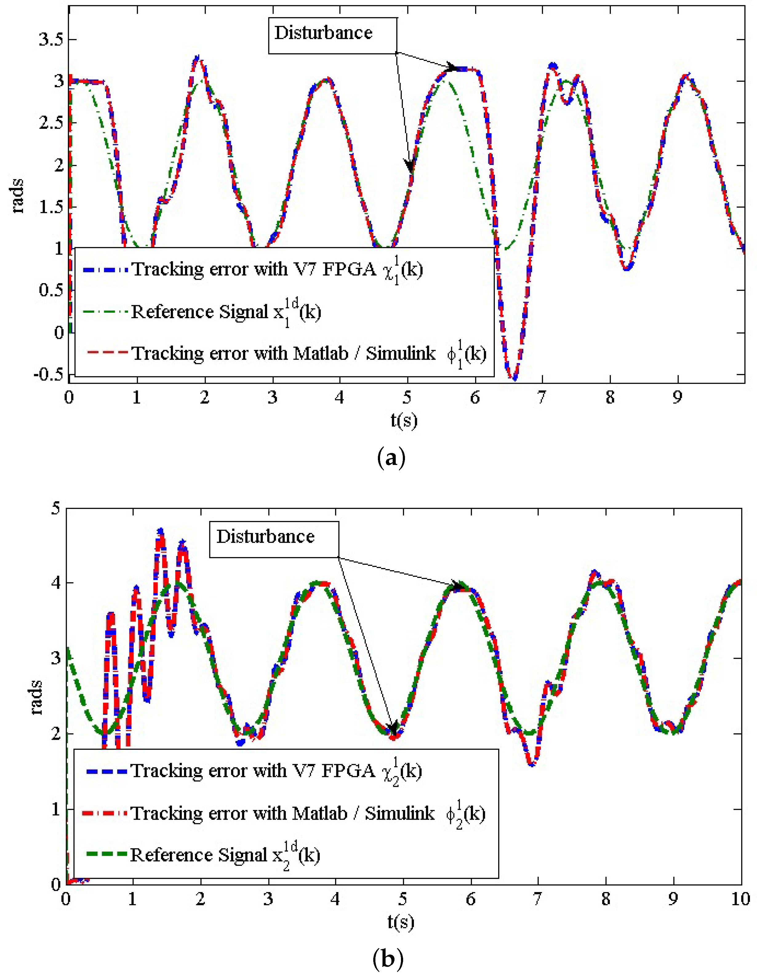
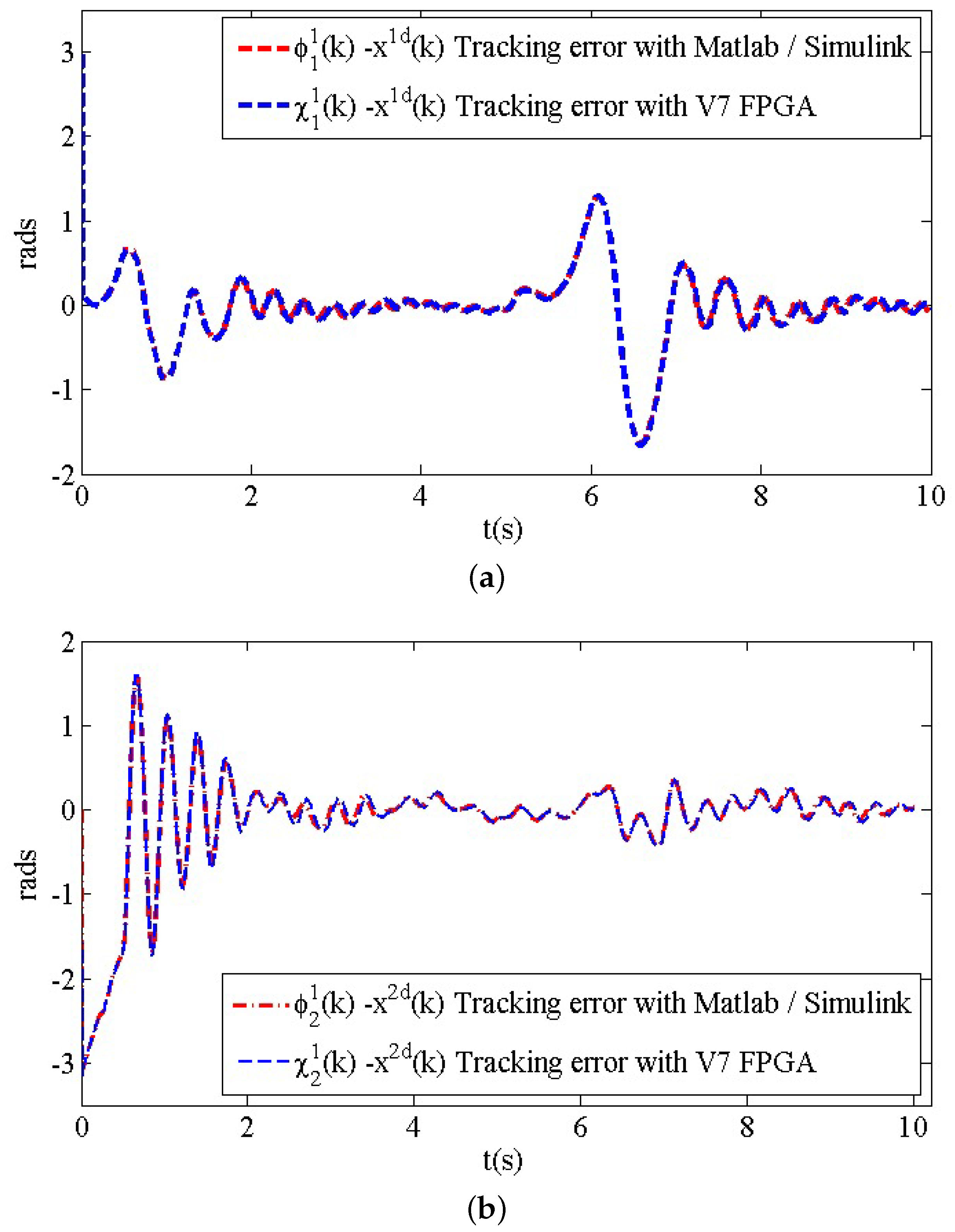
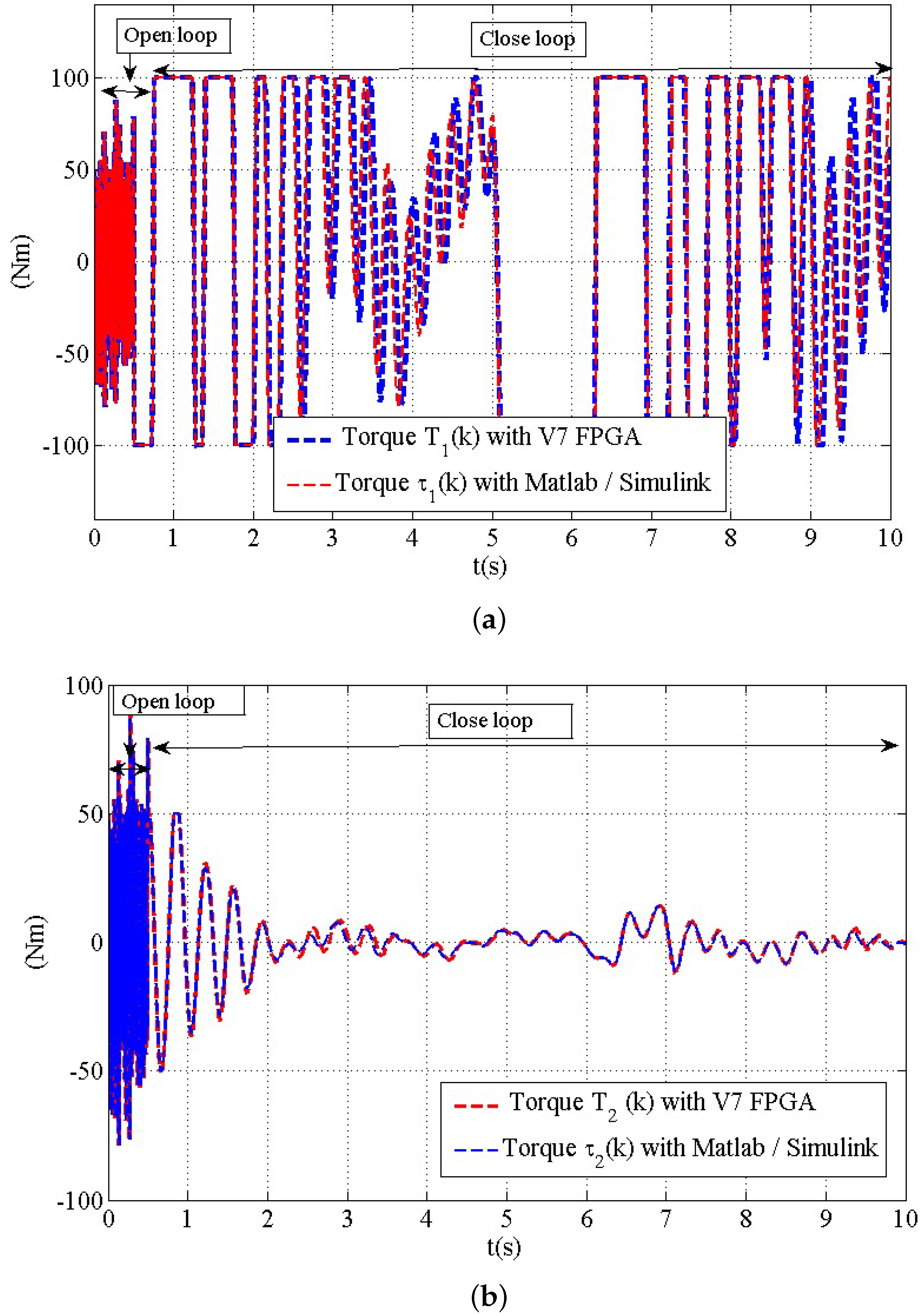
5. Experimental Test and Real Time Results

The identification results are presented in Figure 5a for the first plant state of joint 1, where the identification process used the hardware-in-loop architecture with the FPGA and the real angular position for the first joint. Please note that in Figure 5a the initial condition for the neural identifier is 0. Then, in one step simulation time, the signal of the neural identifier estimates the angular position for the first joint with very good precision. Figure 5b displays the identification error for the first state of joint 1, where e 1 1 ( k ) is the error obtained with the FPGA hardware-in-loop architecture. For simplicity, only the identification of the first state of joint 1 is presented.
The results of the identification procedure shown in Figure 5a,b and explained in this work are completely valid for reducing the estimation error by means of computation of the associated state and measurement noise covariance matrices composed by the coupled variance between the plant states.

Tracking Results

In order to show the tracking simulation results, the following reference signals were applied:
q 1 d ( k ) = χ 1 d ( k ) = x 1 d ( k ) = sin ( ω 1 t ) + 2 rad , q 2 d ( k ) = χ 2 d ( k ) = x 2 d ( k ) = sin ( ω 2 t ) + 3 rad .
with ω 1 = ( 3.5 t + 1 ) rad/s and ω 2 = ( 3 t + 3 ) rad/s. These reference signals were chosen arbitrarily to demonstrate a very good approximation. A sample time of k = 0.001 s is used, and if we then insert them into Equation (17), we obtain the following supply torques:
τ 1 τ 1 m a x ( k ) = 100 Nm , τ 2 τ 2 m a x ( k ) = 50 Nm .
The closed-loop simulation results using the FPGA hardware-in-loop architecture are presented in Figure 6.
The results for this real-time implementation are limited to the robot’s physical parameters. The applied torque in Figure 6 has the maximum value calculated for this controller and it is applied with limitations. An example of this can be if the applied disturbance reaches the limit of the physical resistance of the 2DOF construction material for the present 2DOF robot. It can be pushed to an uncontrolled dynamic behavior. However, the non-modeled dynamics can be tolerated until the 2DOF and the torque applied to the 2DOF resist the external involved perturbances if not reaching the SMC design parameters presented in this paper (Equation (17)).
The system works in open-loop during the interval from 0–0.5 s, and this in order to let the RHONN estimate the state space variables. After this setup period, the system is set in closed-loop. An external disturbance is applied in the interval of time from the fifth to sixth second in a step-wise way. The tracking results for joints 1 and 2 are displayed in Figure 6, and their corresponding tracking errors are shown in Figure 7.
Additionally, in Figure 8 the applied torques are shown. As can be seen in Figure 8a, the applied torques T 1 ( k ) and τ 1 ( k ) reached the maximum value τ 1 m a x ( k ) specified in Equation (25) after approximately 3.4 s of simulation. This is the time in which the system proceeds to the sliding manifold s D 1 ( k ) u ˜ e q 1 ( k ) u 0 1 ( k ) . After these 3.4 s, the control law u 1 ( k ) is a smooth function, which means that the sliding manifold s D 1 ( k ) has been reached u ˜ e q 1 ( k ) > u 0 1 ( k ) . After that the disturbance is applied at 5 s, and in consequence the applied torques goes to the maximum value. This point can be observed in the tracking results shown in Figure 6a and the applied torques T 2 ( k ) and τ 2 ( k ) are shown in Figure 8b. In other words, after the 0.5 s, the value specified in Equation (25) means that the sliding manifold s D 2 ( k ) has been reached immediately thanks to the controller in u ˜ e q 2 ( k ) > u 0 2 ( k ) .
Table 1 contributes with the hardware resource utilization of logic circuits used in the hardware-in-loop architecture for the complete control system, which has the SMC controller and the RHONN neural identifier. This table shows the quantity of DSP48s circuits that were used as arithmetic blocks with floating point variables. It also allows integration of other kind of structures in a training device with an FPGA. The proposed design saves a great deal of resources that can be used for improved versions of the algorithms presented herein, to increase the applicability of this method.

6. Discussion

The main goal of the work presented in this paper was the control system designed for the 2DOF manipulator robot using a RHONN module in a hardware-in-loop setup. As such, we have presented a methodology for identification and tracking of the plant (2DOF) to be controlled. Once the identification and tracking results are reached, the present proposal can be expanded with a real 2DOF implementation, where the mathematical model is unknown and only the state variables are available. The results are obtained without the necessity to know the complete mathematical model of the plant, or the parameters. Even when the results are obtained via a hardware-in-loop configuration, the proposed methodology constitutes an advance in a new control system architecture: the RHONN, modified EKF, and SMC implemented on an FPGA. This is due to the strategy proposed in this work, which guarantees there is no requirement for an exact mathematical model to be reproduced by an FPGA. Furthermore, the contribution of this proposal is in the area of programming a RHONN on an FPGA. The FPGA can compute and solve the problem with this architecture: a RHONN in discrete-time; the modified extended KF algorithm where the associated state and measurement noise covariance matrices are composed by the coupled variance between the plant states; and the decentralized discrete-time sliding mode controller combined with a block control algorithm. The results of the control system with the new combination of the mentioned architectures has been discussed in detail and the experiments show very satisfactory results.
The results of the tracking control and identification process show the high performance of the system, which is a tangible evidence of the new design architecture implemented for discrete nonlinear systems.
This control system architecture has never been solved with this methodology in this field and has not used the XSG, ignoring its potential in the design of complex systems. Using an FPGA and co-design, in tandem with a hardware-in-loop approach, any control can be implemented in the re-configurable hardware for quick simulation and production.

7. Conclusions

The design and implementation of a real-time control system for a 2DOF robot based on a neural network and hardware-in-loop architecture has been presented in this paper, and it is an adequate alternative for a 2DOF manipulator robot performing medical tasks. A decentralized RHONN was trained online with the modified EKF algorithm, where the associated state and measurement noise covariance matrices were composed by the coupled variance between the plant states. Additionally, a sliding-window-based method for dynamical modeling of non-stationary systems with a decentralized SM controller was implemented as an improvement for the 2DOF manipulator robot. In addition, the SM controller was successfully implemented, enabling the system to provide a relative fast-tracking error of the control signal with a slight use of computing resources. FPGA implementation allows a high performance and fast time calculations in a relatively low-cost platform. The testing of the system with virtual stimuli, and the internal acquisition data device provided by the Board Virtex 7/Evaluation kit through the HIL architecture, made the real-time results shown in this paper possible. The use of an FPGA implementation for this problem avoids the necessity to have an external data acquisition device, decreasing the number of circuits for the final design. Additionally, the control system implementation requires a smaller layout for manufacturing the digital circuit in a printed circuit board (PCB).
Future work can be expanded to consider different dynamic systems and SMC variations with new mathematical contributions in the algorithm in discrete time. The control system exposed with this methodology can be used in future work in high-accuracy medical tasks with a high performance.

Author Contributions

Conceptualization, U.D.-G. and C.E.C.; formal analysis, U.D.-G.; investigation, U.D.-G.; methodology, C.E.C., L.M.A.-L., and G.O.-R.; resources, L.M.A.-L.; validation, U.D.-G.; writing—original draft, U.D.-G. and C.E.C.; writing—review and editing, L.M.A.-L. and G.O.-R. All authors have read and agreed to the published version of the manuscript.

Funding

This research received no external funding.

Conflicts of Interest

The authors declare no conflict of interest.

Abbreviations

The following abbreviations are used in this manuscript:
2DOFTwo degrees of freedom
NNNeural networks
EKFExtended Kalman filter
SMCSliding-mode controller
RHONNRecurrent high-order neural network
XSGXilinx system generator
HILHardware-in-loop
KFKalman filtering
FPGAField programmable gate array
PCBPrinted circuit board
v7Virtex 7 FPGA
FFFlip-flop
LUTSLook-up table
IOBsInput/output block
Mults/DSP48SFloating-point multiplier circuit
TBUFs3-state buffer
BRAMsBlock RAM
SlicesBasic building block components in the FPGA fabric

References

  1. Cleary, K.; Melzer, A.; Watson, V.; Kronreif, G.; Stoianovici, D. Interventional robotic systems: Applications and technology state-of-the-art. Minim. Invasive Ther. Allied Technol. 2006, 15, 101–113. [Google Scholar] [CrossRef] [PubMed] [Green Version]
  2. Madoński, R.; Kordasz, M.; Sauer, P. Application of a Disturbance-Rejection Controller for Robotic-Enhanced Limb Rehavbilitation Trainings. ISA Trans. 2014, 53, 899–908. [Google Scholar] [CrossRef] [PubMed]
  3. Hong, J.; Dohi, T.; Hashizume, M.; Konishi, K.; Hata, N. An ultrasound-driven needle-insertion robot for percutaneous cholecystostomy. Phys. Med. Biol. 2004, 49, 441–455. [Google Scholar] [CrossRef] [PubMed]
  4. Guerra, J.F.; García-Hernandez, R.; Llama, M.A. Decentralized Neural Block Control for a Robot Manipulator based in UKF training. In Proceedings of the 2019 International Conference on Electronics, Communications and Computers (CONIELECOMP), Cholula, Mexico, 27 February–1 March 2019; pp. 88–89. [Google Scholar]
  5. Vázquez, L.A.; Jurado, F.; Castañeda, C.E.; Alanis, A.Y. Real-Time Implementation of a Neural Integrator Backstepping Control via Recurrent Wavelet First Order Neural Network. Neural Process. Lett. 2018, 49, 1629–1648. [Google Scholar] [CrossRef]
  6. Slotine, J.E. The Robust Control of Robot Manipulators. Int. J. Robot. Res. 1985, 4, 49–64. [Google Scholar] [CrossRef]
  7. Utkin, I.; Chang, H.-C. Sliding Mode Control on Electro-Mechanical Systems. In Mathematical Problems in Engineering; CRC Press: New York, NY, USA, 1999. [Google Scholar]
  8. Garcia-Hernandez, R.; Sanchez, E.N.; Loukianov, A.G.; Bayro-Corrochano, E.; Santibanez, V. Decentralized Neural Identification and Control for Robotics Manipulators. In Proceedings of the 2006 IEEE Conference on Computer Aided Control System Design, 2006 IEEE International Conference on Control Applications, 2006 IEEE International Symposium on Intelligent Control, Munich, Germany, 4–6 October 2006. [Google Scholar]
  9. Safaric, R.; Rodic, J. Decentralized neural-network sliding-mode robot controller. In Proceedings of the 2000 26th Annual Conference of the IEEE Industrial Electronics Society, Nagoya, Japan, 22–28 October 2000; pp. 906–911. [Google Scholar]
  10. Zhang, J.; Li, Y.; Wu, X. Neural network identification and control for nonlinear dynamic systems with time delay. In Proceedings of the 2015 34th Chinese Control Conference (CCC), Hangzhou, China, 28–30 July 2015; pp. 3524–3529. [Google Scholar]
  11. Wang, L.; Chen, Y.; Li, S.; Liu, C. 2DOF manipulator tracking control based on fuzzy CMAC neural network dynamic inversion. In Proceedings of the 2010 International Conference on Intelligent Computing and Integrated Systems, Guilin, China, 22–24 October 2010; pp. 315–318. [Google Scholar]
  12. Dávalos, U.G.; Castañeda, C.E.; Esquivel, P.; Jurado, F.Z.; Morfín, O.A. Recurrent Neural Identification on Xilinx system generator using V7 FPGA for a 2DOF robot manipulator. In Proceedings of the 2016 International Joint Conference on Neural Networks (IJCNN), Vancouver, BC, Canada, 24–29 July 2016. [Google Scholar]
  13. Utkin, V.I. Sliding mode control design principles and applications to electric drives. IEEE Trans. Ind. Electron. 1993, 40, 23–36. [Google Scholar] [CrossRef] [Green Version]
  14. Castaneda, C.E.; Loukianov, A.G.; Sanchez, E.N.; Bernardino, C.-T. Discrete-time neural sliding-mode block control for a dc motor with controlled flux. IEEE Trans. Ind. Electron. 2012, 59, 1194–1207. [Google Scholar] [CrossRef]
  15. Jouila, A.; Nouri, K. An adaptive robust nonsingular fast terminal sliding mode controller based on wavelet neural network for a 2-DOF robotic arm. J. Frankl. Inst. 2020, 357, 13259–13282. [Google Scholar] [CrossRef]
  16. Bekir, C. Modelling and Controlling of a 3DOF Robot Manipulator with Artificial Neural Networks. Int. J. Sci. Res. Mech. Mater. Eng. 2018, 2, 2457. [Google Scholar]
  17. Andres, O.P.-L.; Ramon, G.-H.; Victor, S.; Jorge, V.C. Experimental Evaluation of a Sectorial Fuzzy Controller Plus Adaptative Neural Network Compensation Applied to a 2-DOF Robot Manipulator. In Proceedings of the 13th IFAC Workshop on Adaptative and Learning Control Systems ALCOS 2019, Winchester, UK, 4–6 December 2019. [Google Scholar]
  18. Jafar, T.; Afshar, S.J.; Muhammad, A.D. A new method for position control of a 2-DOF robot arm using neuro-fuzzy controller. Indian J. Sci. Technol. 2012, 5, 2253–2257. [Google Scholar]
  19. Bahoura, M.; Ezzaidi, H. FPGA-implementation of a sequential adaptive noise canceller using Xilinx System Generator. In Proceedings of the 2009 International Conference on Microelectronics—ICM, Marrakech, Morocco, 19–22 December 2009. [Google Scholar]
  20. Vasquez, V.; Echeverry, J.M.; Contreras, D.E. Design and Statistical Validation of Spark Ignition Engine Electronic Control Unit for Hardware-in-the-Loop Testing. IEEE Lat. Am. Trans. 2017, 15, 1376–1383. [Google Scholar] [CrossRef]
  21. Reyes, F.; Kelly, R. Experimental evaluation of identification schemes on a direct drive robot. Robotica 1997, 15, 563–571. [Google Scholar] [CrossRef]
  22. Spong, M.W.; Vidyasagar, M. Robot Dynamics and Control; Jhonn Wiley and Sons Inc.: New York, NY, USA, 1989. [Google Scholar]
  23. Kazantzis, N.; Kravaris, C. Time-discretization of nonlinear control systems via Taylor methods. Comput. Chem. Eng. 1999, 23, 763–784. [Google Scholar] [CrossRef]
  24. Jurado, F.; Flores, M.A.; Santibanez, V.; Llama, M.A.; Castaneda, C.E. Continuous-Time Neural Identification for a 2 DOF Vertical Robot Manipulator. In Proceedings of the 2011 IEEE Electronics, Robotics and Automotive Mechanics Conference, Cuernavaca, Morelos, Mexico, 15–18 November 2011. [Google Scholar]
  25. Castañeda, C.E.; Esquivel, P. Decentralized neural identifier and control for nonlinear systems based on extended Kalman filter. Neural Netw. 2012, 31, 81–87. [Google Scholar] [CrossRef] [PubMed]
  26. Loukianov, A.G. Robust block decomposition sliding mode control design. Math. Probl. Eng. 2002, 8, 349–365. [Google Scholar] [CrossRef] [Green Version]
Figure 1. Block diagram of proposed control system.
Applsci 11 01154 g001
Figure 2. Neural identifier based on recurrent high-order neural network (RHONN) architecture.
Applsci 11 01154 g002
Figure 3. Real-time implementation of the control system using hardware-in-loop (HIL) architecture.
Applsci 11 01154 g003
Figure 4. Physical real-time implementation using hardware-in-loop architecture.
Applsci 11 01154 g004
Figure 5. (a) Identification results and (b) identification error for the first state of joint 1 x 1 1 ( k ) .
Applsci 11 01154 g005
Figure 6. (a) Angular position tracking results for x 1 1 ( k ) , and (b) for x 2 1 ( k ) .
Applsci 11 01154 g006
Figure 7. Tracking error results (a) for z 1 1 ( k ) and (b) for z 2 1 ( k ) .
Applsci 11 01154 g007
Figure 8. Applied torque for (a) joint 1 and (b) joint 2.
Applsci 11 01154 g008
Table 1. Hardware resource utilization of logic circuits used in the hardware-in-loop architecture.
Device Utilization SummaryNeural Identifier (RHONN + EKF)Control System (RHONN + EKF + SMC)
Used%Used%
Slices62,7549262,69243
FFs198313300920
BRAM0000
LUTs242,46439199,93899
IOB76107811
Mults/DSP48s181864279699
TBUFs0000
Publisher’s Note: MDPI stays neutral with regard to jurisdictional claims in published maps and institutional affiliations.

