
Magnetic Field-Based Vehicle Positioning System in Long Tunnel Environment


Abstract
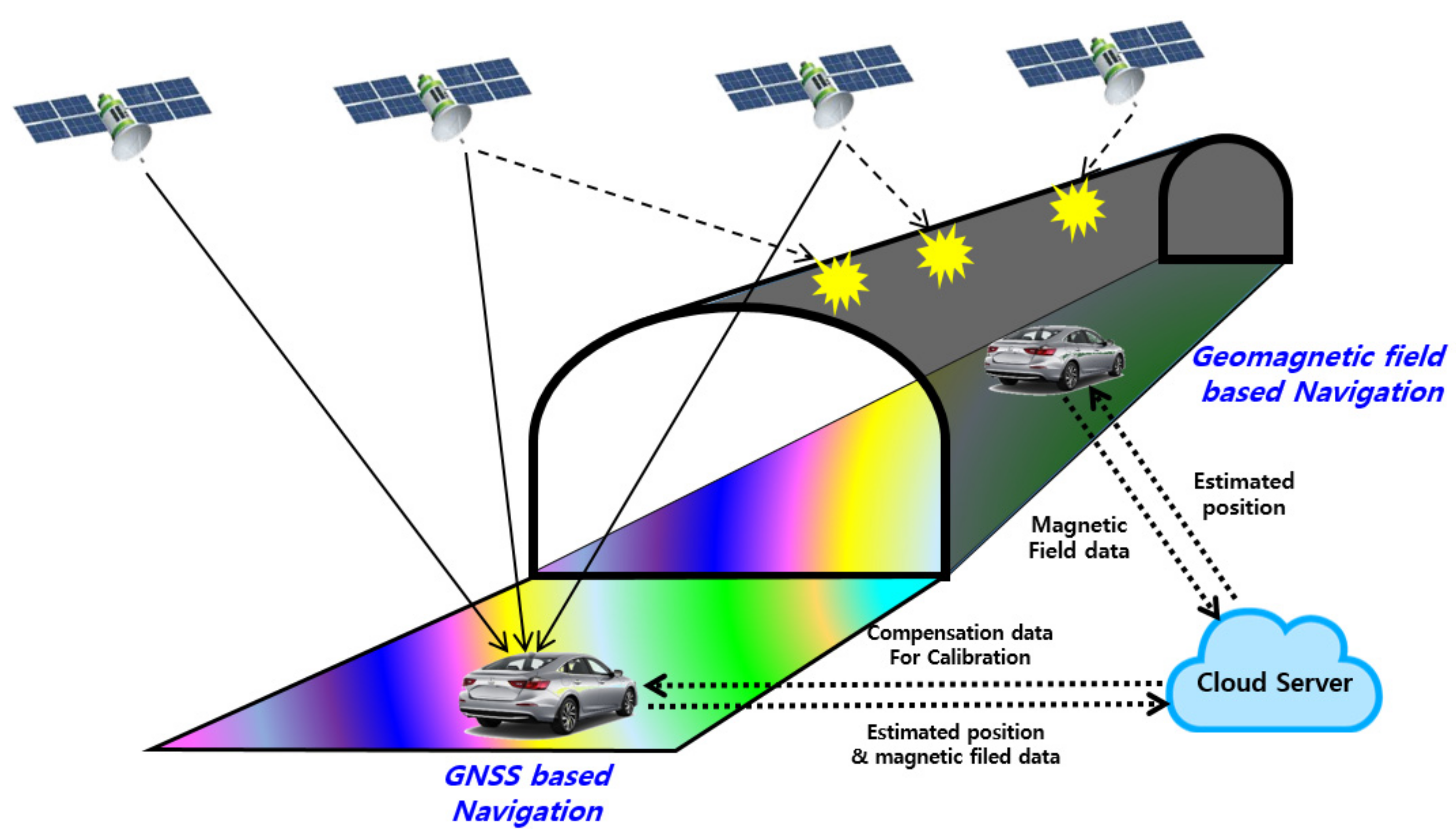
:1. Introduction
- We propose the magnetic field based novel tunnel navigation system for drivers. The driver does not need any additional equipment apart from a smartphone, and there is no cost burden for infrastructure installation, as the magnetic field is utilized. The only requirements are the creation and management of the magnetic field DB.
- We propose a convenient magnetic sensor calibration method for vehicle navigation, and obtained very accurate positioning results using magnetic field data in the tunnel environment.
- In the positioning phase, the magnetic field sequence data are compared with the minor DB using subsequence DTW. By using the minor DB, the computational complexity is reduced and positioning accuracy is enhanced.
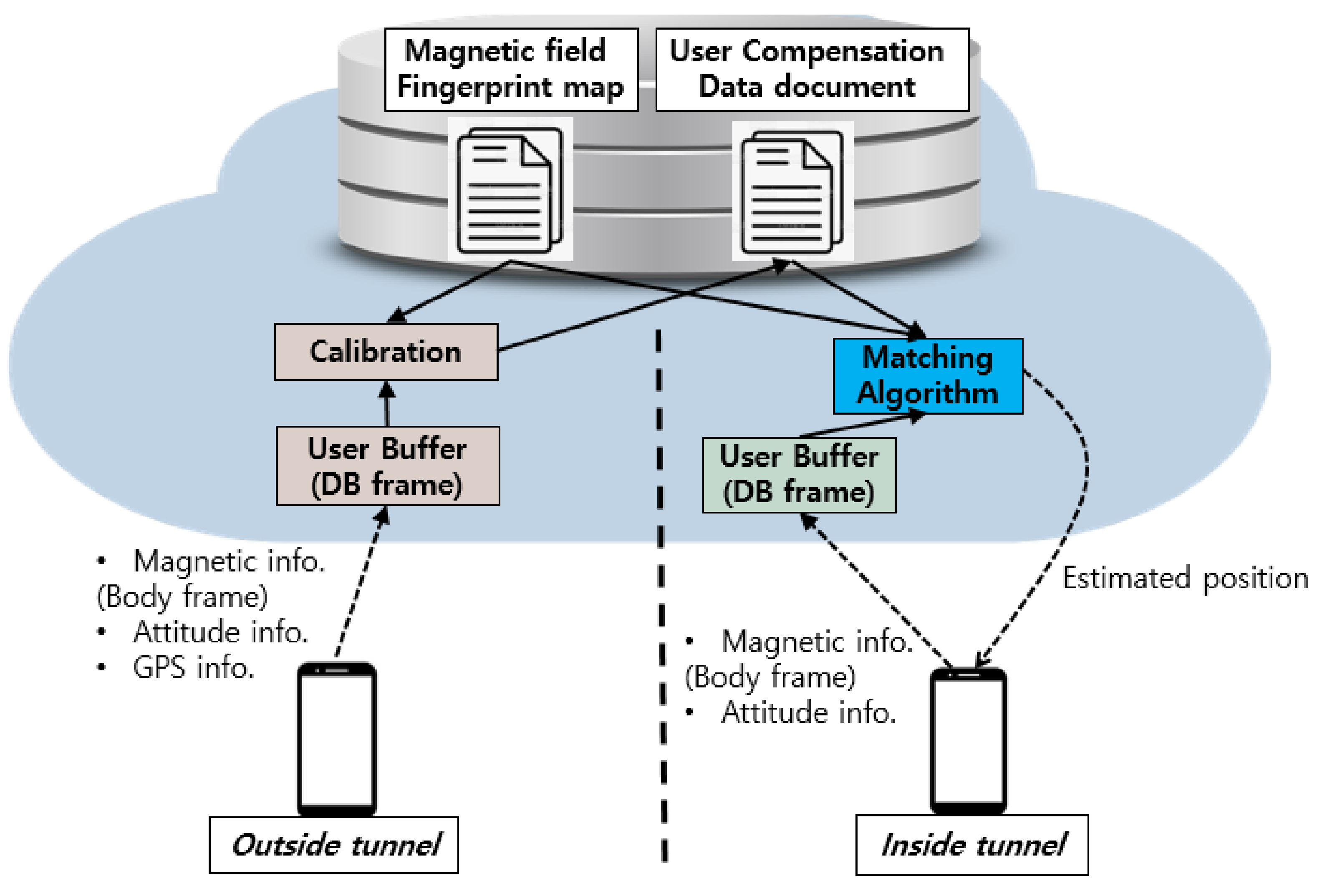
2. System Block Diagram
3. Proposed System Explanation
3.1. Magnetic Field in Tunnel Environment
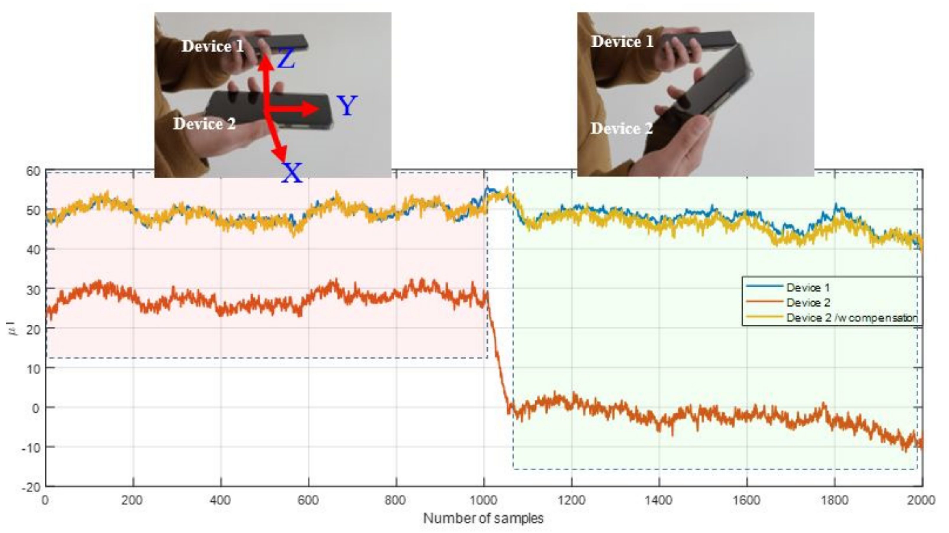
3.2. Device Calibration
3.3. Generation of Magnetic Field DB
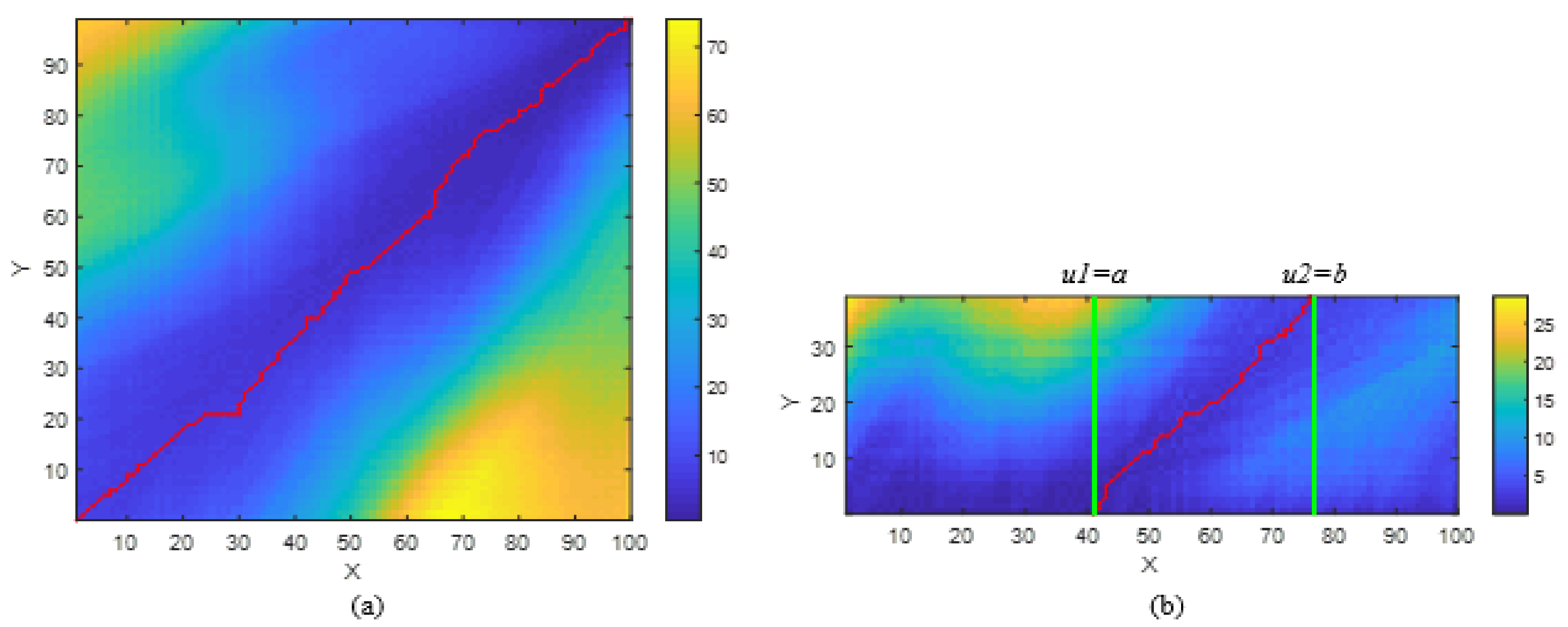
3.4. Subsequence Dynamic Time Warping for Tunnel Environment Positioning
4. Experimental Results and Discussion
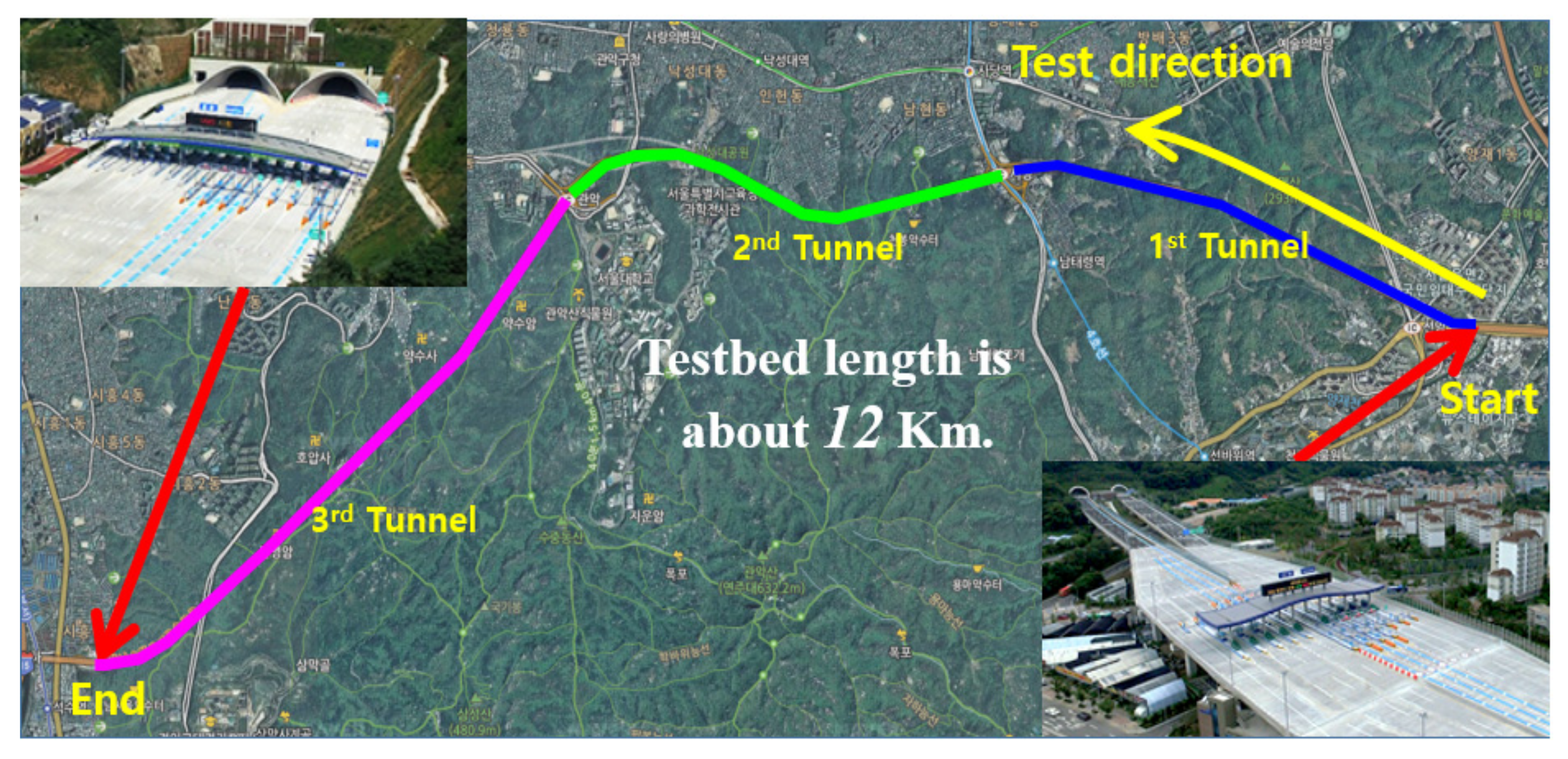
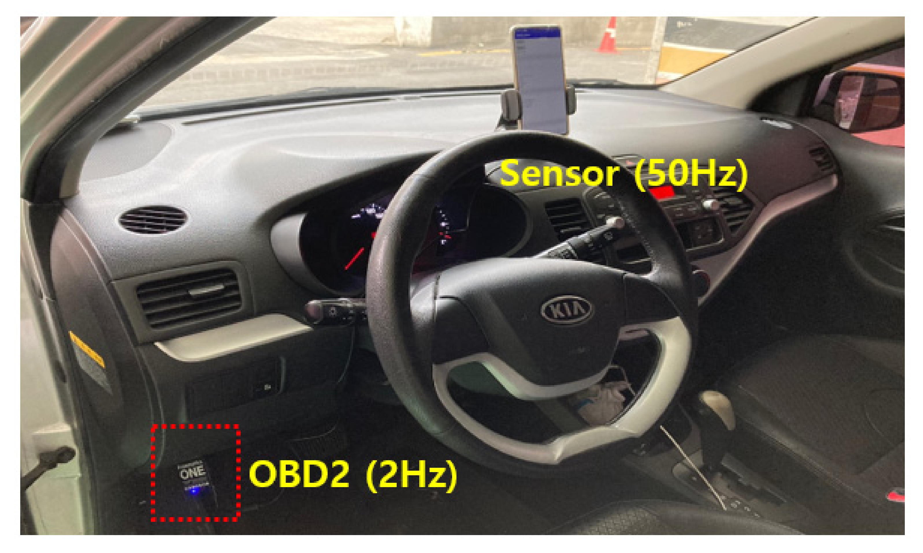
4.1. Test Bed
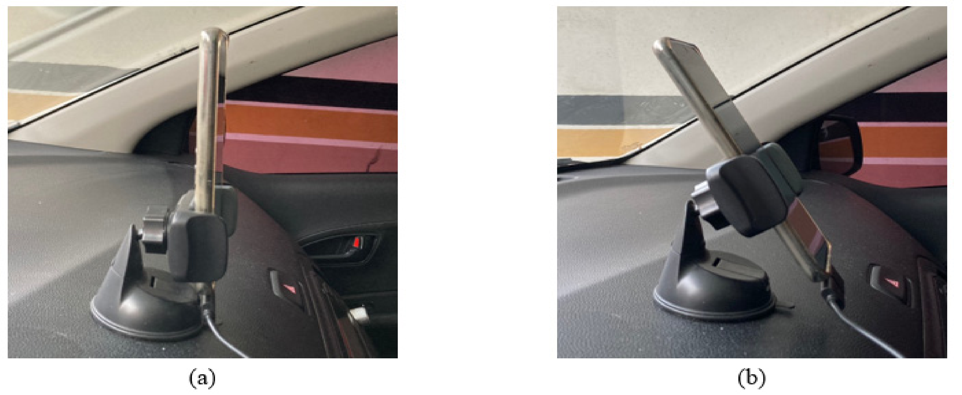
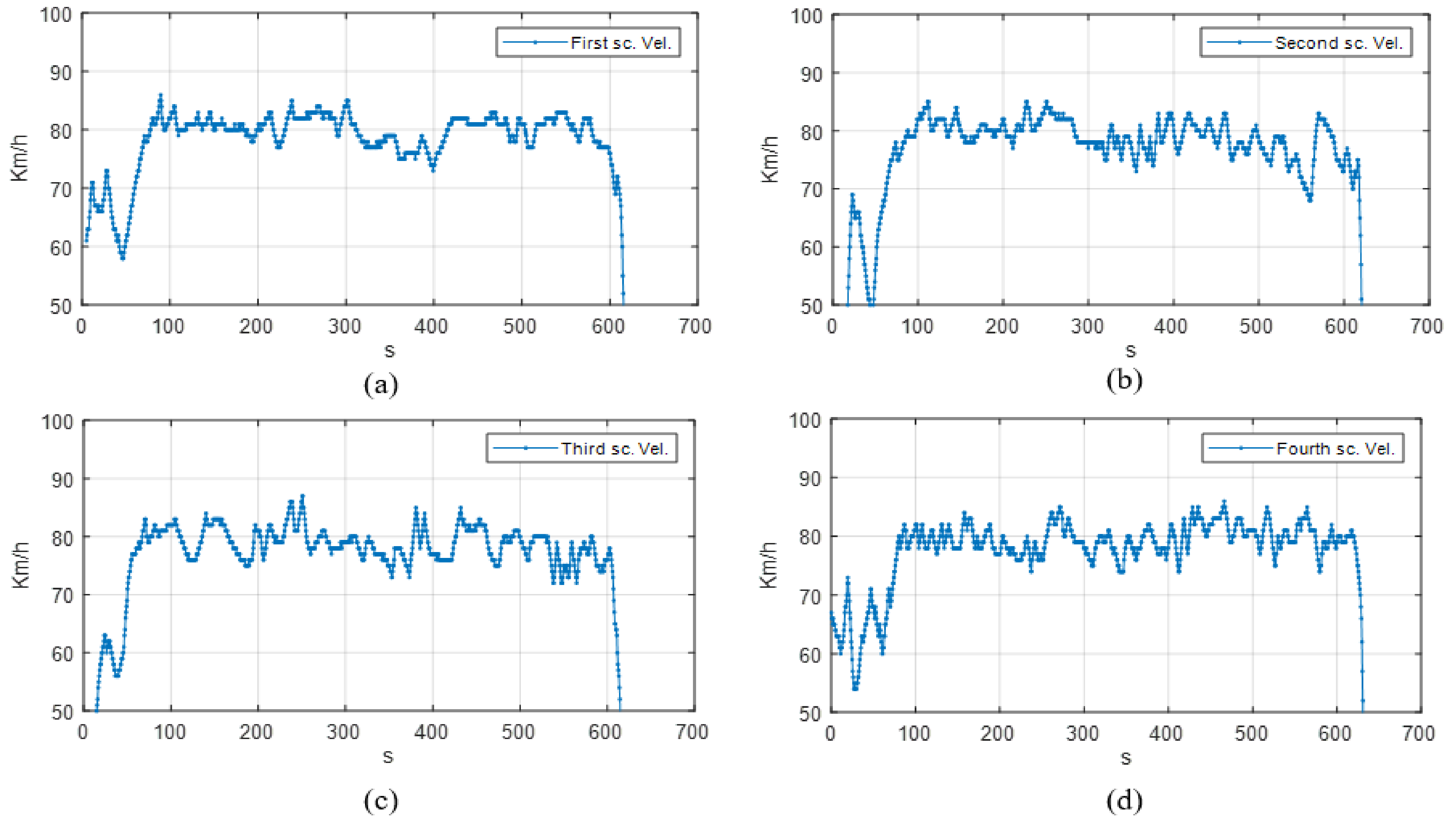
4.2. Test Scenarios Explanation
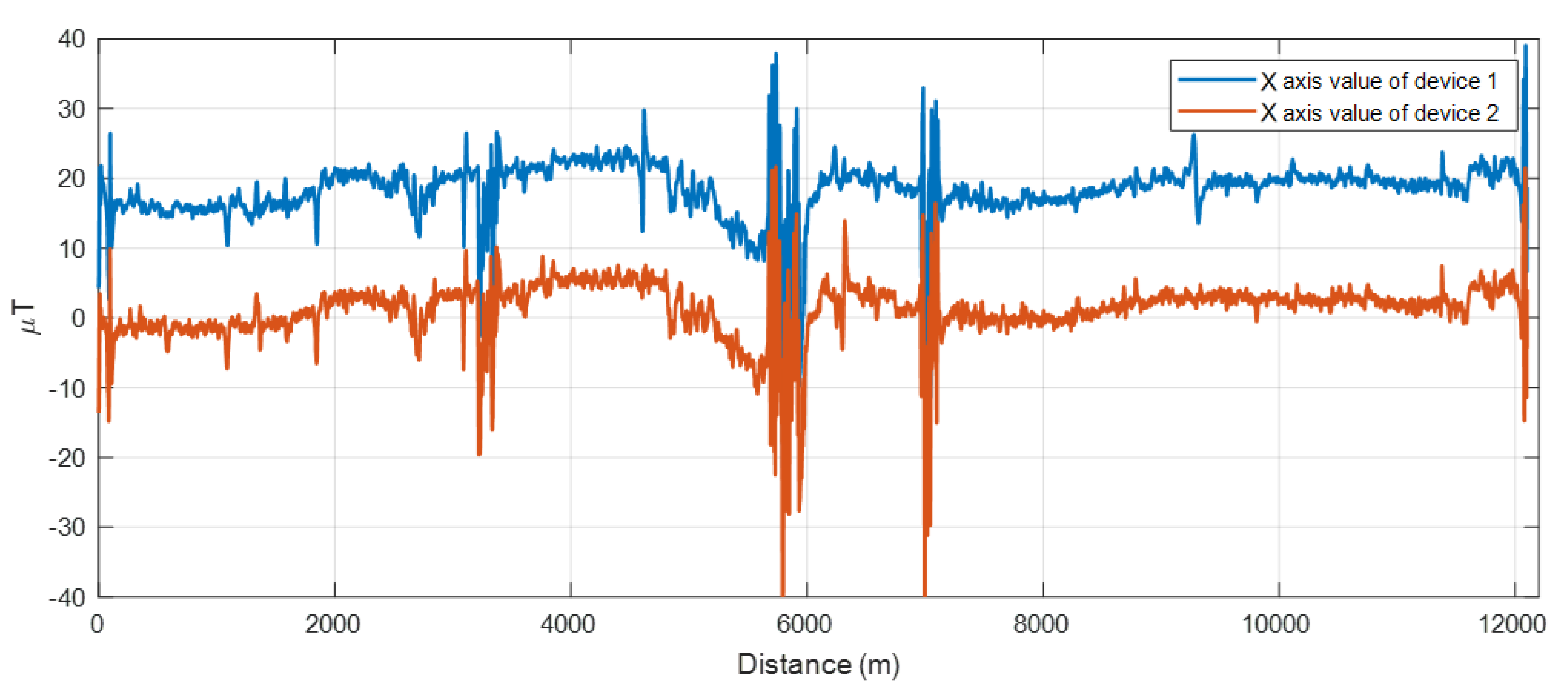
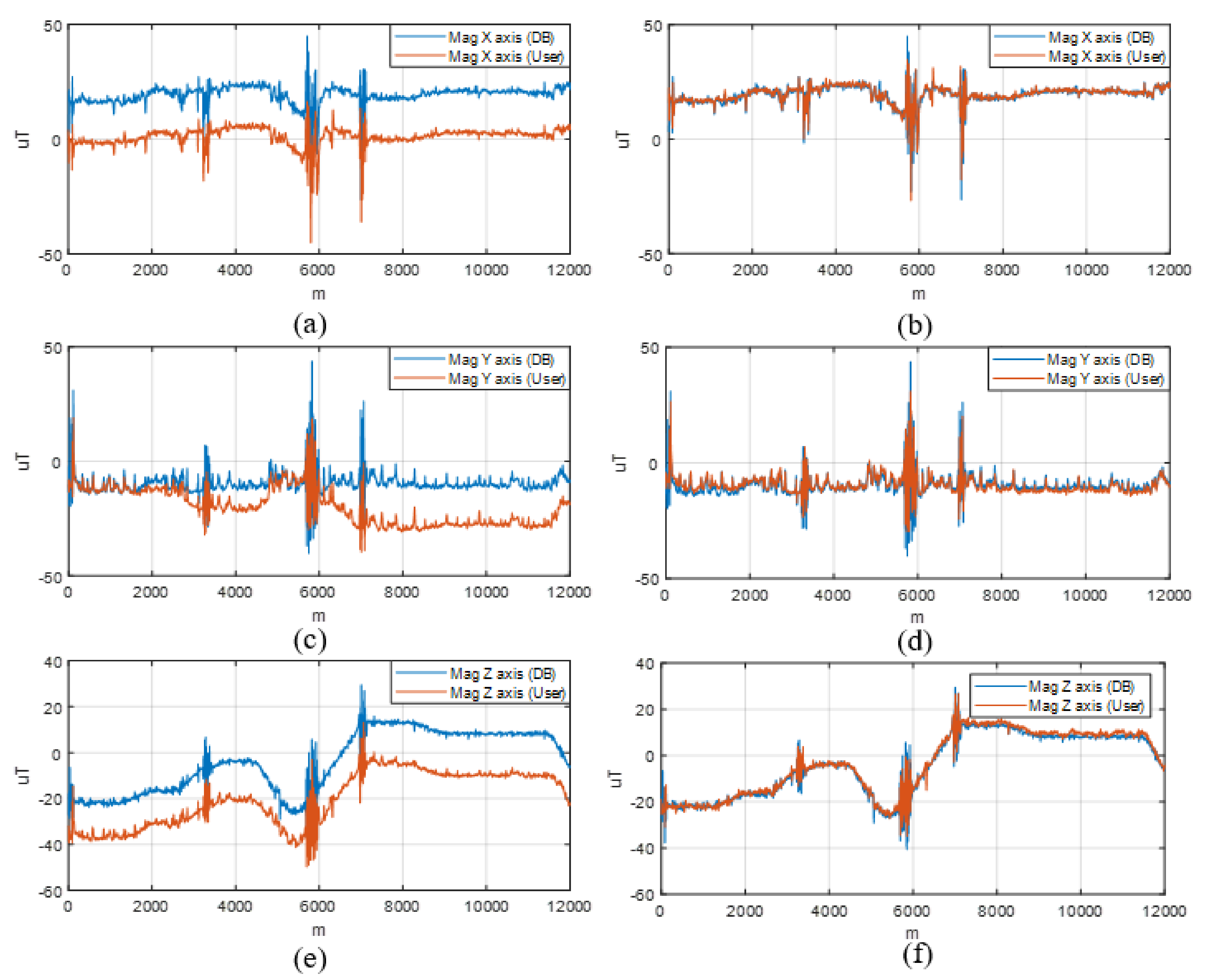
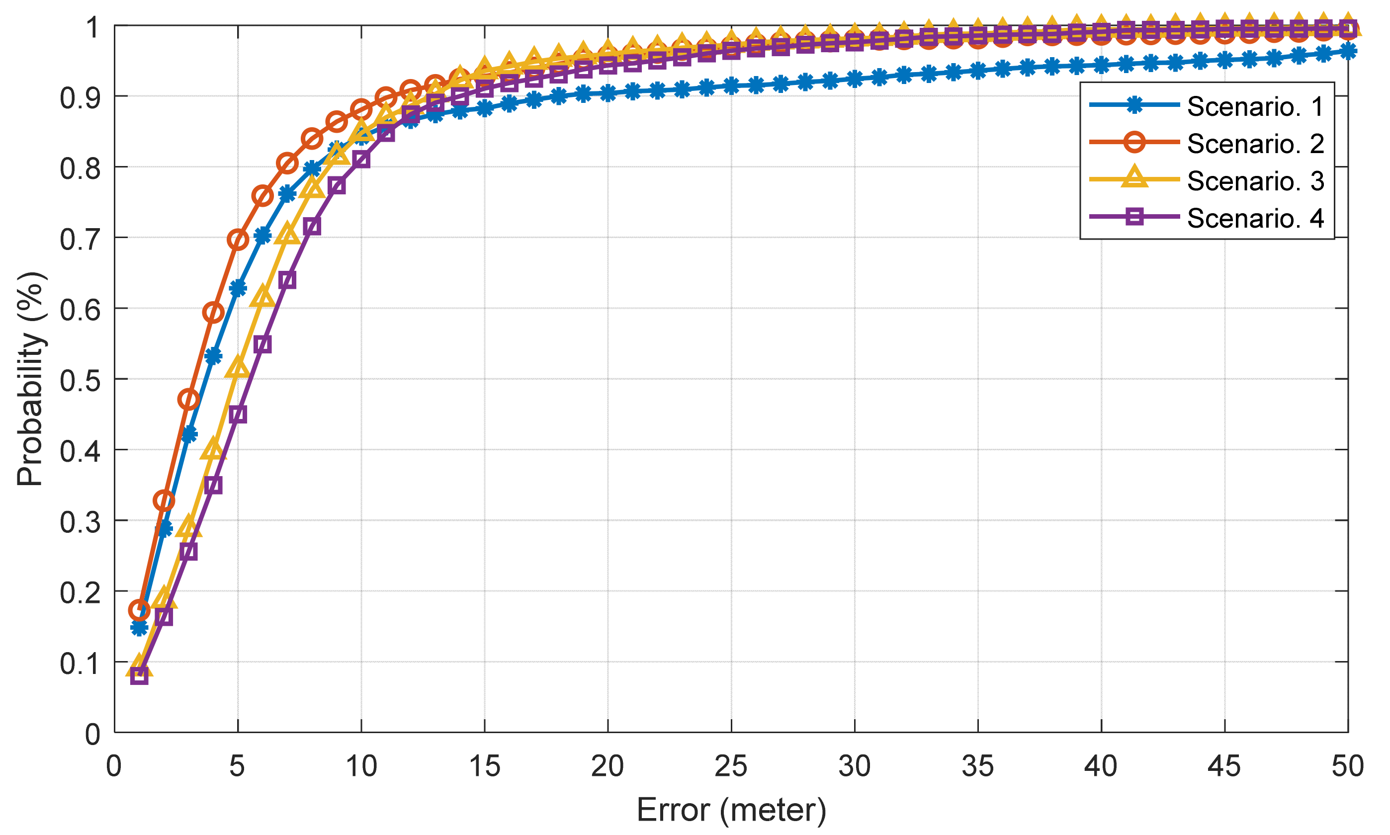
4.3. Experimental Results
4.4. Discussion
5. Conclusions
Author Contributions
Funding
Institutional Review Board Statement
Informed Consent Statement
Data Availability Statement
Conflicts of Interest
References
- Realini, E.; Caldera, S.; Pertusini, L.; Sampietro, D. Precise GNSS positioning using smart devices. Sensors 2017, 17, 2434. [Google Scholar] [CrossRef] [PubMed] [Green Version]
- Shin, B.; Lee, J.H.; Yu, C.; Kim, C.; Lee, T. Underground parking lot navigation system using long-term evolution signal. Sensors 2021, 21, 1725. [Google Scholar] [CrossRef] [PubMed]
- Li, N.; Gao, Y.; Wang, Y.; Liu, Z.; Guan, L.; Liu, X. A low-cost underground garage navigation switching algorithm based on kalman filtering. Sensors 2019, 19, 1861. [Google Scholar] [CrossRef] [PubMed] [Green Version]
- Guo, X.; Ansari, N.; Hu, F.; Shao, Y.; Elikplim, N.R.; Li, L. A survey on fusion-based indoor positioning. IEEE Commun. Surv. Tutorials 2020, 22, 566–594. [Google Scholar] [CrossRef]
- Guo, G.; Chen, R.; Ye, F.; Peng, X.; Liu, Z.; Pan, Y. Indoor Smartphone Localization: A Hybrid WiFi RTT-RSS Ranging Approach. IEEE Access 2019, 7, 176767–176781. [Google Scholar] [CrossRef]
- Shin, B.; Lee, J.H.; Lee, T.; Kim, H.S. Enhanced weighted K-nearest neighbor algorithm for indoor Wi-Fi positioning systems. In Proceedings of the 2012 8th International Conference on Computing Technology and Information Management (NCM and ICNIT), Seoul, Korea, 24–26 April 2012; Volume 2, pp. 574–577. [Google Scholar] [CrossRef]
- Monfared, S.; Nguyen, T.H.; Petrillo, L.; De Doncker, P.; Horlin, F. Experimental Demonstration of BLE Transmitter Positioning Based on AOA Estimation. In Proceedings of the 2018 IEEE 29th Annual International Symposium on Personal, Indoor and Mobile Radio Communications (PIMRC), Bologna, Italy, 9–12 September 2018; pp. 856–859. [Google Scholar] [CrossRef] [Green Version]
- Subbu, K.P.; Gozick, B.; Dantu, R. LocateMe: Magnetic-fields-based indoor localization using smartphones. ACM Trans. Intell. Syst. Technol. 2013, 4, 1–27. [Google Scholar] [CrossRef]
- Alarifi, A.; Al-Salman, A.; Alsaleh, M.; Alnafessah, A.; Al-Hadhrami, S.; Al-Ammar, M.A.; Al-Khalifa, H.S. Ultra wideband indoor positioning technologies: Analysis and recent advances. Sensors 2016, 16, 707. [Google Scholar] [CrossRef] [PubMed]
- Bisio, I.; Lavagetto, F.; Marchese, M.; Sciarrone, A. Smart probabilistic fingerprinting for WiFi-based indoor positioning with mobile devices. Pervasive Mob. Comput. 2016, 31, 107–123. [Google Scholar] [CrossRef]
- Cypriani, M.; Delisle, G.; Hakem, N. Wi-Fi-based positioning in underground mine tunnels. In Proceedings of the International Conference on Indoor Positioning and Indoor Navigation, Montbeliard, France, 28–31 October 2013; pp. 28–31. [Google Scholar] [CrossRef]
- Qin, Y.; Zhou, C.; Yang, S.H.; Wang, F. A distributed newton iteration based localization scheme in underground tunnels. In Proceedings of the 2012 UKACC International Conference on Control, Cardiff, UK, 3–5 September 2012; pp. 851–856. [Google Scholar] [CrossRef]
- Song, X.; Li, X.; Tang, W.; Zhang, W.; Li, B. A hybrid positioning strategy for vehicles in a tunnel based on rfid and in-vehicle sensors. Sensors 2014, 14, 23095–23118. [Google Scholar] [CrossRef] [PubMed] [Green Version]
- Islam, A.; Hossain, M.A.; Le, N.T.; Hong, C.H. Precise Localization in Tunnel Environment using Visible Light Communication. In Proceedings of the 26th Joint Conference on Communications and Information, Lisbon, Portugal, 26–28 July 2016. [Google Scholar]
- Kim, B.W.; Jung, S.Y. Vehicle positioning scheme using V2V and V2I visible light communications. In Proceedings of the 2016 IEEE 83rd Vehicular Technology Conference (VTC Spring), Nanjing, China, 15–18 May 2016; pp. 1–5. [Google Scholar] [CrossRef]
- Li, C.R.; Xie, J.L.; Yang, L.L. Angle offset-assisted positioning of railway vehicles in tunnel environments. In Proceedings of the 2015 IEEE 81st Vehicular Technology Conference (VTC Spring), Glasgow, UK, 11–14 May 2015. [Google Scholar] [CrossRef]
- Li, B.; Gallagher, T.; Dempster, A.G.; Rizos, C. How feasible is the use of magnetic field alone for indoor positioning? In Proceedings of the 2012 International Conference on Indoor Positioning and Indoor Navigation (IPIN), Sydney, Australia, 13–15 November 2012. [Google Scholar] [CrossRef]
- Galván-Tejada, C.E.; Zanella-Calzada, L.A.; García-Domínguez, A.; Magallanes-Quintanar, R.; Luna-García, H.; Celaya-Padilla, J.M.; Galván-Tejada, J.I.; Vélez-Rodríguez, A.; Gamboa-Rosales, H. Estimation of Indoor Location Through Magnetic Field Data: An Approach Based on Convolutional Neural Networks. ISPRS Int. J. Geo-Inf. 2020, 9, 226. [Google Scholar] [CrossRef] [Green Version]
- Galván-Tejada, C.E.; García-Vázquez, J.P.; Brena, R.F. Magnetic field feature extraction and selection for indoor location estimation. Sensors 2014, 14, 11001–11015. [Google Scholar] [CrossRef] [PubMed] [Green Version]
- Al-homayani, F.; Mahoor, M. Improved indoor geomagnetic field fingerprinting for smartwatch localization using deep learning. In Proceedings of the 2018 IEEE International Conference on Indoor Positioning and Indoor Navigation (IPIN), Nantes, France, 24–27 September 2018; pp. 1–8. [Google Scholar]
- Xie, H.; Gu, T.; Tao, X.; Ye, H.; Lv, J. MaLoc: A practical magnetic fingerprinting approach to indoor localization using smartphones. In Proceedings of the 2014 ACM International Joint Conference on Pervasive and Ubiquitous Computing, Seattle, WA, USA, 13–17 September 2014. [Google Scholar] [CrossRef]
- Müller, M. Information Retrieval for Music and Motion; Springer: Berlin/Heidelberg, Germany, 2007; ISBN 9783540740476. [Google Scholar]
- Stout, T.A.; Sparrow, V.W. Time-domain spline interpolation in a simulation of N-wave propagation through turbulence. J. Acoust. Soc. Am. 2018, 229, EL229–EL235. [Google Scholar] [CrossRef] [PubMed] [Green Version]


| Scenario Number | Smartphone Model | Smartphone Attitude |
|---|---|---|
| 1 | Galaxy 9+ | Figure 11a |
| 2 | Galaxy 9+ | Figure 11b |
| 3 | Galaxy 20 Ultra | Figure 11a |
| 4 | Galaxy 20 Ultra | Figure 11b |
| Mean (m) | RMSE (m) | CEP90 (m) | |
|---|---|---|---|
| Sc. 1 | 9.28 | 30.38 | 16.16 |
| Sc. 2 | 5.39 | 9.49 | 7.07 |
| Sc. 3 | 6.44 | 9.33 | 4.09 |
| Sc. 4 | 7.25 | 10.46 | 7.65 |
Publisher’s Note: MDPI stays neutral with regard to jurisdictional claims in published maps and institutional affiliations. |
© 2021 by the authors. Licensee MDPI, Basel, Switzerland. This article is an open access article distributed under the terms and conditions of the Creative Commons Attribution (CC BY) license (https://creativecommons.org/licenses/by/4.0/).
Share and Cite
Shin, B.; Lee, J.-H.; Yu, C.; Kyung, H.; Lee, T. Magnetic Field-Based Vehicle Positioning System in Long Tunnel Environment. Appl. Sci. 2021, 11, 11641. https://doi.org/10.3390/app112411641
Shin B, Lee J-H, Yu C, Kyung H, Lee T. Magnetic Field-Based Vehicle Positioning System in Long Tunnel Environment. Applied Sciences. 2021; 11(24):11641. https://doi.org/10.3390/app112411641
Chicago/Turabian StyleShin, Beomju, Jung-Ho Lee, Changsu Yu, Hankyeol Kyung, and Taikjin Lee. 2021. "Magnetic Field-Based Vehicle Positioning System in Long Tunnel Environment" Applied Sciences 11, no. 24: 11641. https://doi.org/10.3390/app112411641
APA StyleShin, B., Lee, J.-H., Yu, C., Kyung, H., & Lee, T. (2021). Magnetic Field-Based Vehicle Positioning System in Long Tunnel Environment. Applied Sciences, 11(24), 11641. https://doi.org/10.3390/app112411641