Article

Potential Use of Cold Plasma Discharges for Frequency Reconfigurability in a Sievenpiper Mushroom Metasurface

by
Francisco Pizarro
1,*,†,
Pablo Stuardo
1,†,
Ricardo Olivares
2,† and
Eva Rajo-Iglesias
3,†
1
Escuela de Ingeniería Eléctrica, Pontificia Universidad Católica de Valparaíso, Valparaíso 2362804, Chile
2
Department of Electronic Engineering, Universidad Técnica Federico Santa María, Valparaíso 2390123, Chile
3
Department of Signal Theory and Communications, University Carlos III of Madrid, 28911 Leganés, Spain
*
Author to whom correspondence should be addressed.
All authors contributed equally to this work.
Appl. Sci. 2021, 11(23), 11342; https://doi.org/10.3390/app112311342
Submission received: 22 October 2021 / Revised: 22 November 2021 / Accepted: 25 November 2021 / Published: 30 November 2021
(This article belongs to the Special Issue Low-Temperature Plasma and Its Applications)

Abstract

:
This article presents a parametric study using full-wave simulations about the potential use of cold plasma discharges to achieve frequency reconfiguration on a Sievenpiper mushroom metasurface. The study was done by inserting plasma tubes in between the patches of the mushroom structure, in three different positions with respect to the top of the metasurface, and varying the electronic density while keeping the plasma collision frequency. The obtained results show that it is possible to shift the stop-band generated by the metasurface around 25% towards lower frequencies for an electron density value inside the tubes of 10 14 cm 3 , when they are placed in between the top patches of the metasurface. Additional insertion losses are exhibited when operating near the plasma frequency.

1. Introduction

Metasurfaces are structures that have physic properties that are not found in nature regarding how they interact with electromagnetic (EM) waves [1]. Usually made of periodic structures, they have interesting properties such as being able to synthesize perfect magnetic conductor (PMC) boundary conditions allowing the creation of stop-bands for the EM waves, or to behave as a material with controllable graded refractive index, these two properties being what allow the control of the EM wave propagation. These structures have been largely used in many applications oriented to communication technologies. Just to name a few, there are applications related to the optimization of feeding networks for antenna arrays [2,3], circuit packaging [4,5], dielectric and metallic lenses with graded refractive index [6,7,8], suppression of undesired cavity modes [9,10], prisms used for leaky wave antennas [11], and many other applications oriented to terrestrial and satellite communications [12]. One advantage of metasurfaces with respect to standard technologies, besides their outstanding physical properties, is that they can be made at a relatively low-cost and have a low-profile [13]. This advantage made them serious candidates to overcome the challenges for the next generation of communication systems, including satellite communications or any high-rate communication system that needs precise and efficient topologies [14,15]. One drawback of metasurfaces is that they are frequency dependent; therefore, the exploration of structures agile in frequency is interesting for a system that includes these topologies.
The implementation of reconfigurable metasurfaces is recognized as an important field for future technologies, and there is evidence of efforts in that direction in the recent years [15]. To achieve reconfigurability regarding the electromagnetic properties of the metasurface, it is necessary to integrate active tunable devices or tunable materials within the neighbor cells that can change the overall properties of the structure. For example, we can find the use of varactors or pin diodes to manipulate different properties of the metasurface [16,17,18] and the use of tunable materials such as liquid crystals and other ferroelectric materials to achieve reconfiguration [19,20]. However, there is still a gap to be studied for topologies that can handle higher power densities for reconfiguration, in which plasma discharges can be a candidate [15].
Plasma discharges are not new in terms of their use in high-frequency applications. The main characteristic of cold plasma discharges is that, when an electromagnetic wave is impinging on a plasma, it can be reflected, absorbed, or transmitted with a specific phase shift [21]. In other words, a plasma acts as a conducting or a dielectric material whose complex relative permittivity ε p is a function of its electron density n e , its electron-neutral momentum transfer collision frequency ν p , and the angular frequency ω of the incident electromagnetic wave. Depending on these three parameters, the real part of ε p can be negative, equal to zero, or positive with a value between 0 and 1. Such electromagnetic properties have led to several applications in the field of antennas and microwave circuits [22,23,24,25]. In particular, plasma parameters can be controlled by external variables, such as the power injected to the discharge that has a direct influence on the electron density, and the gas pressure, and this has an influence over the plasma collision frequency [26]. This characteristic makes the cold plasma discharge suitable for the implementation of reconfigurable high-frequency devices, due to the active control and variation of the plasma permittivity, and therefore the variation of how the EM wave interacts with the discharge and the device [27,28,29,30,31,32].
In this study, we propose the assessment of a reconfigurable Sievenpiper mushroom metasurface [33] using plasma tubes as the active device by varying the electron density to achieve a frequency shift of the stop-band generated by the metasurface.

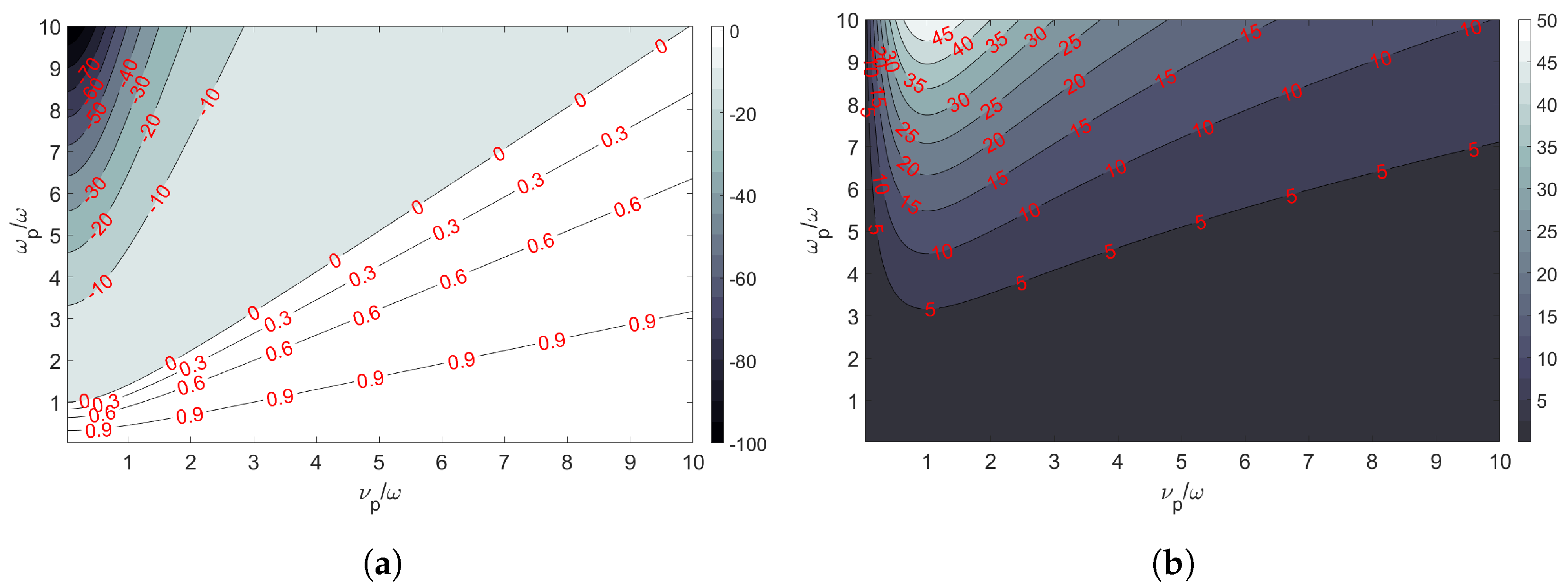
2. Cold Plasma Characteristics

A plasma is an ionized gas, macroscopically neutral. To generate a plasma, the neutral gas has to receive enough energy so that its ionization degree reaches a level that changes the gas macroscopic properties from an insulator to a conducting medium. Many structures can be used to couple the energy to the gas, but in this study we will focus on plasmas generated by applying a static electric field to the gas. Due to our conditions of excitation, the type of plasma we are dealing with in this study is defined as a non-equilibrium or cold plasma. One characteristic of a cold plasma is that the heavy particles keep their temperature close to the room temperature while the electrons are warmed enough to produce collisions. One way to describe a plasma medium is by considering its ionization degree δ , which is given by [26]:
δ = n e n e + n o
with n e the electron density and n o the neutral density. The plasma used in this study exhibits an ionization degree δ lower than 10 4 . A homogeneous cold plasma can be viewed as a dielectric medium whose complex relative permittivity ε p is described by the Drude’s model [26]
ϵ p = 1 ω p 2 ω 2 j ν p ω
where ω represents the angular frequency of the electromagnetic wave interacting with the plasma, ν p the plasma electron-neutral momentum transfer frequency, hereafter referred to as collision frequency, and ω p the plasma angular frequency defined as:
ω p = n e e 2 ϵ 0 m e
with n e the electron density, e the electron charge, ϵ 0 the vacuum permittivity, and m e the electron mass. From Equations (2) and (3), we can see that the complex permittivity ε p of a homogeneous cold plasma depends on n e and ν p . Actually, n e is related to the power injected to the discharge, the type of gas, and its pressure, while ν p depends mainly on the type of gas and its pressure. We can theoretically control the permittivity of a plasma, and so modify the way it interacts with an incident electromagnetic wave. In a realistic system, however, the control of the power injected to the plasma discharge is the only one that can be easily implemented in real time. In practice, we can also describe the Drude’s model as a function of the ratios ω p / ω and ν p / ω , as shown in Equation (4):
ε p = ε j ε = 1 ( ω p / ω ) 2 1 + ( ν p / ω ) 2 j ( ν p / ω ) ( ω p / ω ) 2 1 + ( ν p / ω ) 2 .
Figure 1 shows the values for the real and imaginary parts of the plasma permittivity as a function of the ratios ω p / ω and ν p / ω . From Figure 1, we can see that the real part ( ε ) becomes negative when ω p > ω , while the imaginary part of the permittivity ( ε ) is maximum when ν p / ω 1 , which means that we can expect additional losses due to the plasma medium.
If the Drude’s model helps in understanding the interaction between an incident electromagnetic wave and a homogeneous cold plasma, a real plasma remains an inhomogeneous medium. In fact, it exhibits a complex electron density distribution which is often difficult to assess. Nevertheless, for confined discharges, it can give a good estimation on the behavior when integrated into a high-frequency circuit [34].

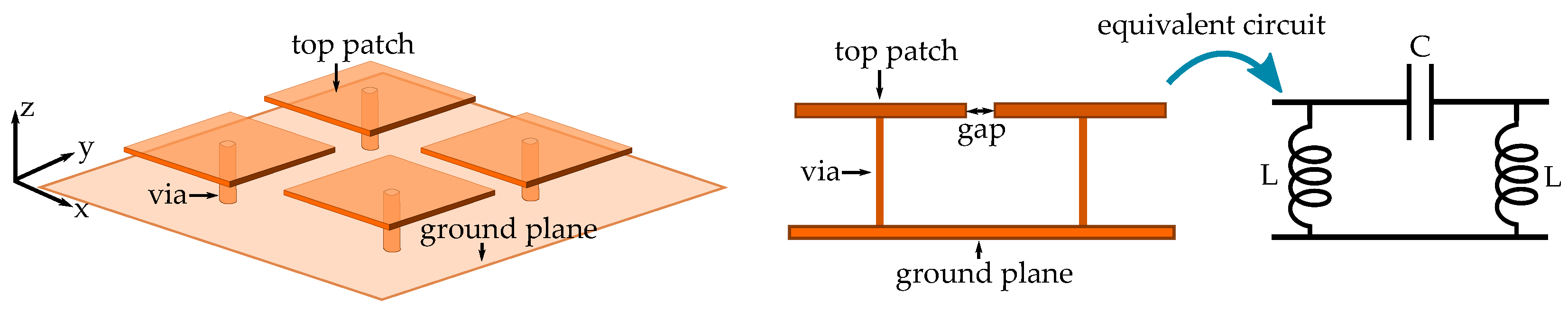
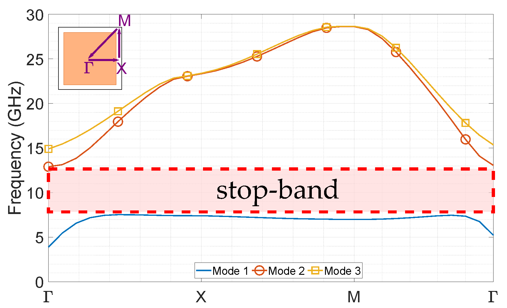
3. Metasurface Design

The metasurface that is going to be analyzed, and where the plasma discharge will be inserted, is the known Sievenpiper mushroom [16]. This structure consists of a metallic patch, normally etched on a dielectric substrate, grounded with a metallic via. When used in a periodic lattice configuration, the existing gap between two adjacent patches behaves as a capacitor and the grounded via as an inductor, which together generate a resonant circuit and therefore induce a high-impedance surface at the correspondent resonant frequency. This condition avoids the propagation of surface waves within a band called stop-band or band-gap. Figure 2 shows a description of the mushroom-like Sievenpiper metasurface and its equivalent electric circuit for two adjacent mushrooms. From this circuit, we can have the equivalent surface impedance Z s for the structure, as exposed in Equation (5) [1]. However, with this analysis, we cannot obtain properly the stop-band generated by this lattice:
Z s = j ω L 1 ω 2 L C
To evaluate the stop-band generated by this structure, we proceed to do an irreducible Brillouin zone analysis, from which we can retrieve its dispersion diagram and therefore the frequency range where there are no propagating modes [16,35]. This analysis is done using the software ANSYS HFSS [36], where a unit cell of the mushroom structure is implemented and analyzed. The unit cell is shown in Figure 3 and the obtained dispersion diagram is shown in Figure 4. For this simulation, all the conductors are considered as perfect electric conductors (PEC), while the substrate used is a PTFE composite whose electrical characteristics correspond to a ROGERS 5870, with a relative permittivity ε r = 2.33 . To notice that we have added a top plate over the mushroom separated with an air gap, to have a structure similar to the one that will be used on the final simulations. The dimensions used for the unit cell are the following: p = 4.55 mm, g a p = 3.5 mm, h s u b = 3.175 mm, l m = w m = 2.8 mm, g = 3.5 mm and ϕ = 0.36 mm.
The resulting dispersion diagram shows a stop-band generated between the first and second modes that can propagate, which has a low cutoff frequency of 7.7 GHz and a high cutoff frequency of 12.8 GHz. However, and in order to implement the metasurface, we will assess its behavior in a full-wave wideband simulation. For that, we will design a 8 × 5 mushroom lattice to be inserted into a parallel plate configuration of lateral dimensions W s u b = L s u b = 50 mm to be simulated. In Figure 5, the designed mushroom lattice is shown in the simulation configuration used to assess the transmission losses, and therefore the frequencies where the stop-band is generated.
Figure 6 shows the transmission coefficient | S 21 | as a function of the frequency for the parallel plate waveguide simulation with the metasurface inserted, compared to the same parallel plate structure without the metasurface. We can see that, for this structure, there is a good agreement between the cutoff frequencies of the stop-band obtained on the eigenmode analysis and in the full wave simulation of the structure.

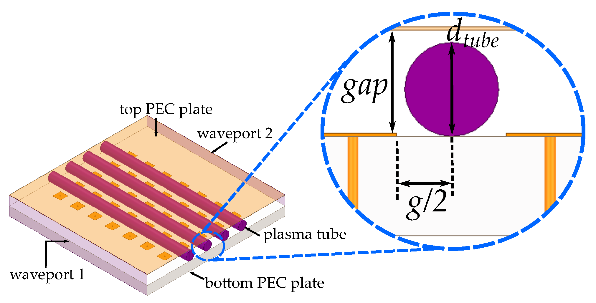
4. Plasma Discharge Integration

For the plasma discharge integration, we use similar properties retrieved from plasma tubes previously used on other studies [34]. For these simulations, we will use tubes that have a plasma diameter of d t u b e = 3 mm, which is filled with a gas that exhibits a plasma collision frequency of ν p = 10 10 1/s. The latter is a value that can be expected for Neon tubes at pressures values around 40 torr [34]. We will place a simulated plasma tube in between the gaps of the mushroom structure. The objective of this placement is to vary the capacitance that exists between two adjacent plates of the mushroom structure with the variable permittivity introduced by the plasma discharge when changing the injected power to the discharge (i.e., increasing the electron density). The dimensions of the plasma tube used for simulations are described in Figure 7.
The interaction of the plasma tubes will be assessed in terms of the power injected to the discharge and to their relative position with respect to the mushroom metallic cap of the periodic structure and the substrate. Three different positions of the tubes will be evaluated: on top of the metallic cap and the substrate, half of the tube inserted on the substrate, being in-line with the mushroom cap, and a full insertion on the substrate, being below the metallic cap of the mushroom. The different positions have different scopes, the placement on top of the substrate being easier to integrate in future implementations, while the other insertions will require mechanically modifying the substrate. The different assessed positions of the tubes with respect the substrate are presented in Figure 8.

5. Results

To assess the effect of the plasma discharge on the metasurface behavior and its possible reconfiguration, we have included the plasma tubes in between a 8 × 5 mushroom structure in which its permittivity is modeled using the Drude’s model. For the model, we use four different electron density values, going from 10 × 10 11 cm 3 to 10 × 10 14 cm 3 . The tubes are modeled to have a plasma collision frequency ν p = 10 10 1/s, which are achievable values for plasma tubes used in previous experimentation [34]. The plasma permittivity obtained with these values of n e and ν p are shown in Figure 9.
Once the plasma tube parameters are defined, we proceed to simulate the metasurface with plasma inserted into the parallel plate condition, with the three different tube positions with respect to the substrate and the top metallic cap of the mushroom (top, middle, and below) and varying the electron density. The simulated transmission coefficients for the previously described conditions are shown in Figure 10. We can see from the results that, for all the configurations, the discharges produce a shift in the stop-band generated by the mushroom lattice. As expected, we can see the stop-band shift when the electron density takes values of 10 13 cm 3 and 10 14 cm 3 , while, for low values of n e , as the permittivity is close to the unit, its behavior is close to a vacuum condition. It is important to notice that, even if the frequency shift of the stop-band goes towards lower frequencies, the shift is not linear when we look to the assessed values of n e .
Another remarkable result is that the frequency reconfiguration is more important when the tubes are placed in the middle configuration, which can be expected as the plasma permittivity will have a more direct interaction with the capacitance that is produced between each patch of the metasurface. We can see that, for the case when n e = 10 14 cm 3 , the lower cutoff frequency of the stop-band shifts around 2 GHz (from 8 GHz to 6 GHz approx.). We can see a particular behavior for the n e = 10 12 cm 3 and n e = 10 13 cm 3 cases. For the case when the electron density is n e = 10 12 cm 3 , we can see that there are important losses in transmission in the lower part of the band, before the stop-band regime. This can be explained with permittivity exhibited by the plasma, which is close to zero, and therefore is close to the plasma oscillation frequency. However, when we go higher in frequency, the permittivity is close to a vacuum behavior, which can be seen in the increment of the transmission coefficient being close to that case scenario. A similar behavior is observed for the case when n e = 10 13 cm 3 , where its permittivity is close to zero in the higher part of the assessed band, and even if it exhibits a reconfiguration of the lower cutoff frequency of the stop-band, the higher part exhibits higher transmission losses due to the plasma characteristics. Finally, the bottom case has some particular results as it has a lower shift when compared to the middle case, the case when n e = 10 12 cm 3 has similar behavior to the lower electron densities cases. These differences can be explained by the fact that the tubes now are an important part of the substrate, which modifies differently the behavior of the metasurface.
One last analysis to be done is with respect to the electric field inside the parallel plate structure. For this, we assess the case when the tubes are half inserted through the substrate between the top patches of the metasurface. The electric field is assessed at the middle of the air gap between the top plate and the metasurface patches. The resulting simulated magnitude of the electric field at five different frequencies for all the electron density cases is shown in Figure 11. From the figure, we can see how the lower cutoff frequency of the stop-band is shifted when increasing n e , avoiding the electric field to pass through the structure depending on the frequency over the assessed band. In addition, we can see from the resulting electric fields that, for a given electron density, when the frequency is close to the plasma frequency (or the permittivity is close to zero values), the electric field in the tubes tends to increase, which can explain the additional losses observed in transmission.

6. Conclusions

This article presents a parametric study using full-wave simulations of the potential use of cold plasma discharges to achieve frequency reconfigurability in a Sievenpiper mushroom metasurface. The results were obtained in three different case scenarios depending on the relative position of the tubes with respect to the substrate, while varying the electron density of the plasma, which can be done by injecting more power to the discharge. The results shows that it is feasible to modify the stop-band frequency, with a tendency to shift towards lower frequencies for the higher electron density values assessed in this study, however not exhibiting a linear behavior. In order to avoid additional losses, the study shows that is important to avoid operation near the plasma frequency. This can be easily controlled or predicted with the plasma pressure and electron density using Drude’s model for plasma permittivity.

Author Contributions

The contributions of the authors are summarized as follows: Conceptualization, all authors; Methodology, all authors; Formal Analysis, all authors; Investigation, all authors; Writing—Original draft preparation, all authors; Writing—Review and editing, all authors. All authors have read and agreed to the published version of the manuscript.

Funding

This research was funded by ANID FONDECYT INICIACION 11180434 and DI-PUCV 039.437.

Conflicts of Interest

The authors declare no conflict of interest.

References

  1. Engheta, N.; Ziolkowski, R. Metamaterials: Physics and Engineering Explorations, 1st ed.; Wiley, John and Sons: Hoboken, NJ, USA, 2006. [Google Scholar]
  2. Tamayo-Domínguez, A.; Fernández-González, J.M.; Sierra-Castañer, M. 3D-Printed Modified Butler Matrix Based on Gap Waveguide at W-Band for Monopulse Radar. IEEE Trans. Microw. Theory Tech. 2020, 68, 926–938. [Google Scholar] [CrossRef]
  3. Afifi, I.; Sebak, A.R. Wideband 4 × 4 Butler Matrix in the Printed Ridge Gap Waveguide Technology for Millimeter-Wave Applications. IEEE Trans. Antennas Propag. 2020, 68, 7670–7675. [Google Scholar] [CrossRef]
  4. Pucci, E.; Rajo-Iglesias, E.; Kildal, P.S. New Microstrip Gap Waveguide on Mushroom-Type EBG for Packaging of Microwave Components. IEEE Microw. Wirel. Compon. Lett. 2012, 22, 129–131. [Google Scholar] [CrossRef] [Green Version]
  5. Brazalez, A.A.; Zaman, A.U.; Kildal, P.S. Improved Microstrip Filters Using PMC Packaging by Lid of Nails. IEEE Trans. Compon. Packag. Manuf. Technol. 2012, 2, 1075–1084. [Google Scholar] [CrossRef] [Green Version]
  6. Zetterstrom, O.; Hamarneh, R.; Quevedo-Teruel, O. Experimental Validation of a Metasurface Luneburg Lens Antenna Implemented With Glide-Symmetric Substrate-Integrated Holes. IEEE Antennas Wirel. Propag. Lett. 2021, 20, 698–702. [Google Scholar] [CrossRef]
  7. Poyanco, J.M.; Zetterstrom, O.; Castillo-Tapia, P.; Fonseca, N.J.; Pizarro, F.; Quevedo-Teruel, O. Two-Dimensional Glide-Symmetric Dielectric Structures for Planar Graded-Index Lens Antennas. IEEE Antennas Wirel. Propag. Lett. 2021. [Google Scholar] [CrossRef]
  8. Quevedo-Teruel, O.; Miao, J.; Mattsson, M.; Algaba-Brazalez, A.; Johansson, M.; Manholm, L. Glide-Symmetric Fully Metallic Luneburg Lens for 5G Communications at Ka-Band. IEEE Antennas Wirel. Propag. Lett. 2018, 17, 1588–1592. [Google Scholar] [CrossRef]
  9. Zaman, A.U.; Alexanderson, M.; Vukusic, T.; Kildal, P.S. Gap Waveguide PMC Packaging for Improved Isolation of Circuit Components in High-Frequency Microwave Modules. IEEE Trans. Compon. Packag. Manuf. Technol. 2014, 4, 16–25. [Google Scholar] [CrossRef] [Green Version]
  10. Monasterio, D.; Castro, N.; Pizarro, J.; Pizarro, F.; Mena, F.P. A Mode-Suppressing Metasurface for Large-Width MMICs Suitable for Tightly-Packaged Millimeter and Submillimeter Heterodyne Receivers. IEEE Trans. Terahertz Sci. Technol. 2021. [Google Scholar] [CrossRef]
  11. Memeletzoglou, N.; Rajo-Iglesias, E. Holey Metasurface Prism for the Reduction of the Dispersion of Gap Waveguide Leaky-Wave Antennas. IEEE Antennas Wirel. Propag. Lett. 2019, 18, 2582–2586. [Google Scholar] [CrossRef]
  12. Sanchez-Cabello, C.; Herran, L.F.; Rajo-Iglesias, E. Ka-Band Diplexer for 5G mmWave Applications in Inverted Microstrip Gap Waveguide Technology. Electronics 2020, 9, 2094. [Google Scholar] [CrossRef]
  13. Stuardo, P.; Pizarro, F.; Rajo-Iglesias, E. 3D-Printed Sievenpiper Metasurface Using Conductive Filaments. Materials 2020, 13, 2614. [Google Scholar] [CrossRef] [PubMed]
  14. Bariah, L.; Mohjazi, L.; Muhaidat, S.; Sofotasios, P.C.; Kurt, G.K.; Yanikomeroglu, H.; Dobre, O.A. A Prospective Look: Key Enabling Technologies, Applications and Open Research Topics in 6G Networks. IEEE Access 2020, 8, 174792–174820. [Google Scholar] [CrossRef]
  15. Quevedo-Teruel, O.; Chen, H.; Díaz-Rubio, A.; Gok, G.; Grbic, A.; Minatti, G.; Martini, E.; Maci, S.; Eleftheriades, G.V.; Chen, M.; et al. Roadmap on metasurfaces. J. Opt. 2019, 21, 073002. [Google Scholar] [CrossRef]
  16. Sievenpiper, D.; Schaffner, J.; Song, H.; Loo, R.; Tangonan, G. Two-dimensional beam steering using an electrically tunable impedance surface. IEEE Trans. Antennas Propag. 2003, 51, 2713–2722. [Google Scholar] [CrossRef] [Green Version]
  17. Kim, S.; Wakatsuchi, H.; Rushton, J.J.; Sievenpiper, D.F. Switchable nonlinear metasurfaces for absorbing high power surface waves. Appl. Phys. Lett. 2016, 108, 041903. [Google Scholar] [CrossRef] [Green Version]
  18. Luo, Z.; Chen, X.; Long, J.; Quarfoth, R.; Sievenpiper, D. Self-focusing of electromagnetic surface waves on a nonlinear impedance surface. Appl. Phys. Lett. 2015, 106, 211102. [Google Scholar] [CrossRef]
  19. Couch, A.; Grbic, A. A phase-tunable, liquid crystal-based metasurface. In Proceedings of the 10th International Congress on Advanced Electromagnetic Materials in Microwaves and Optics (METAMATERIALS), Chania, Greece, 19–22 September 2016; pp. 94–96. [Google Scholar] [CrossRef]
  20. Cure, D.; Weller, T.M.; Price, T.; Miranda, F.A.; Van Keuls, F.W. Low-Profile Tunable Dipole Antenna Using Barium Strontium Titanate Varactors. IEEE Trans. Antennas Propag. 2014, 62, 1185–1193. [Google Scholar] [CrossRef]
  21. Vidmar, R. On the use of atmospheric pressure plasmas as electromagnetic reflectors and absorbers. IEEE Trans. Plasma Sci. 1990, 18, 733–741. [Google Scholar] [CrossRef]
  22. Melazzi, D.; Lancellotti, V.; Capobianco, A.D. Analytical and Numerical Study of a Gaseous Plasma Dipole in the UHF Frequency Band. IEEE Trans. Antennas Propag. 2017, 65, 7091–7101. [Google Scholar] [CrossRef]
  23. Sadeghikia, F. Analysis of Plasma Monopole Antenna Using Numerical Method and an Equivalent Circuit. IEEE Antennas Wirel. Propag. Lett. 2017, 16, 1711–1714. [Google Scholar] [CrossRef]
  24. Anderson, T. Plasma Antennas, 2nd ed.; Artech House: Norwood, MA, USA, 2020. [Google Scholar]
  25. Cross, L.W.; Almalkawi, M.J.; Devabhaktuni, V.K. Theory and Demonstration of Narrowband Bent Hairpin Filters Integrated With AC-Coupled Plasma Limiter Elements. IEEE Trans. Electromagn. Compat. 2013, 55, 1100–1106. [Google Scholar] [CrossRef]
  26. Raizer, Y.P. Gas Discharge Physics; Springer: Berlin, Germany, 1991. [Google Scholar]
  27. Sokoloff, J.; Pascal, O.; Callegari, T.; Pascaud, R.; Pizarro, F.; Liard, L.; Lo, J.; Kallel, A. Non-thermal plasma potentialities for microwave device reconfigurability. C. R. Phys. 2014, 15, 468–478. [Google Scholar] [CrossRef] [Green Version]
  28. Pascaud, R.; Pizarro, F.; Callegari, T.; Liard, L.; Pigaglio, O.; Pascal, O. Low insertion loss microplasma-based limiter integrated into a microstrip bandpass filter. Electron. Lett. 2015, 51, 1090–1092. [Google Scholar] [CrossRef] [Green Version]
  29. Pizarro, F.; Pascaud, R.; Pascal, O.; Callegari, T.; Liard, L. Evaluation of microplasma discharges as active components for reconfigurable antennas. In Proceedings of the 6th European Conference on Antennas and Propagation (EUCAP), Prague, Czech Republic, 26–30 March 2012; pp. 117–119. [Google Scholar] [CrossRef] [Green Version]
  30. Jusoh, M.T.; Lafond, O.; Colombel, F.; Himdi, M. Performance and Radiation Patterns of a Reconfigurable Plasma Corner-Reflector Antenna. IEEE Antennas Wirel. Propag. Lett. 2013, 12, 1137–1140. [Google Scholar] [CrossRef] [Green Version]
  31. Sadeghikia, F.; Dorbin, M.R.; Horestani, A.K.; Noghani, M.T.; Ja’afar, H. Tunable Inverted-F Antenna Using Plasma Technologies. IEEE Antennas Wirel. Propag. Lett. 2019, 18, 702–706. [Google Scholar] [CrossRef]
  32. Kamboj, G.K.; Yadav, R.P.; Kaler, R.S. Development of Reconfigurable Plasma Column Antenna. IEEE Trans. Plasma Sci. 2021, 49, 656–662. [Google Scholar] [CrossRef]
  33. Sievenpiper, D.; Zhang, L.; Broas, R.; Alexopolous, N.; Yablonovitch, E. High-impedance electromagnetic surfaces with a forbidden frequency band. IEEE Trans. Microw. Theory Tech. 1999, 47, 2059–2074. [Google Scholar] [CrossRef] [Green Version]
  34. Arkhipenko, V.I.; Callegari, T.; Simonchik, L.V.; Sokoloff, J.; Usachonak, M.S. One-dimensional electromagnetic band gap structures formed by discharge plasmas in a waveguide. J. Appl. Phys. 2014, 116, 123302. [Google Scholar] [CrossRef]
  35. Memeletzoglou, N.; Sanchez-Cabello, C.; Pizarro-Torres, F.; Rajo-Iglesias, E. Analysis of Periodic Structures Made of Pins Inside a Parallel Plate Waveguide. Symmetry 2019, 11, 582. [Google Scholar] [CrossRef] [Green Version]
  36. ANSYS. Available online: https://www.ansys.com (accessed on 9 October 2021).
Figure 1. Plasma permittivity as a function of the ω p / ω and ν p / ω ratios. (a) Real part; (b) Imaginary part.
Applsci 11 11342 g001
Figure 2. Sievenpiper mushroom-like metasurface and its equivalent electric circuit.
Applsci 11 11342 g002
Figure 3. Proposed Sievenpiper mushroom metasurface. Left: cross-view; Right: top-view.
Applsci 11 11342 g003
Figure 4. Dispersion diagram of the three first modes for the proposed mushroom metasurface.
Applsci 11 11342 g004
Figure 5. Mushroom-like metasurface inserted into a parallel plate condition for simulation. (a) top view of the metasurface; (b) full-wave simulation configuration.
Applsci 11 11342 g005
Figure 6. | S 21 | with metasurface, compared to the same structure without metasurface.
Applsci 11 11342 g006
Figure 7. Simulation configuration of the metasurface integrating the plasma tubes with its corresponding dimensions.
Applsci 11 11342 g007
Figure 8. Different configurations of the relative position of the tubes with respect to the substrate and the mushroom cap. (a) top of the substrate and mushroom metallic cap; (b) half inserted in the substrate, in-line with the mushroom metallic cap; (c) below the mushroom metallic cap.
Applsci 11 11342 g008
Figure 9. Plasma tube real permittivity at ν p = 10 10 1/s as a function of the frequency for different electron densities n e (a) n e = 10 11 and n e = 10 12 cm 3 ; (b) n e = 10 13 and n e = 10 14 cm 3 .
Applsci 11 11342 g009
Figure 10. Simulated | S 21 | for the metasurface with plasma tubes in three different configurations. (a) Plasma tubes on top; (b) Plasma tubes on the middle; (c) Plasma tubes below.
Applsci 11 11342 g010
Figure 11. Simulated electric field magnitude at five different frequencies over the assessed band (5 GHz, 7 GHz, 9 GHz, 11 GHz, and 13 GHz) for different values of n e , when the plasma tubes are in line with the top patch of the mushroom structure.
Applsci 11 11342 g011
Publisher’s Note: MDPI stays neutral with regard to jurisdictional claims in published maps and institutional affiliations.

