Abstract
The friction behavior in the tool-chip interface is an essential issue in aluminum matrix composite material (AMCM) turning operations. Compared with conventional cutting, the elliptical vibration (EVC) cutting AMCM has attractive advantages, such as low friction, small cutting forces, etc. However, the friction mechanism of the EVC cutting AMCM is still inadequate, especially the model for cutting forces analyzing and predicting, which hinders the application of EVC in the processing of AMCM. In this paper, a cutting force prediction model for EVC cutting SiCp/Al is established, which is based on the three-phase friction (TPF) theory. The friction components are evaluated and predicted at the tool-chip interface (TCI), tool-particle interface (TPI) and tool-matrix (TMI), respectively. In addition, the tool-chip contact length and SiC particle volume fraction were defined strictly and the coefficient of friction was predicted. Based on the Johnson-Cook constitutive model, the experiment was conducted on SiCp/Al. The cutting speed and tool-chip contact length were used as input parameters of the friction model, and the dynamic changes of cutting force and stress distribution were analyzed. The results shown that when cutting speed reaches 574 m/min, the tool-chip contact length decreases to 0.378 mm. When the cutting speed exceeds 658 m/min, the cutting force decreases to a minimum of 214.9 N and remains stable. In addition, compared with conventional cutting, the proposed prediction model can effectively reduce the cutting force.
1. Introduction
Aluminum-based composite material is a high-quality composite material composed of an aluminum metal matrix and a certain volume fraction of silicon carbide particles [1]. Various thermal expansion coefficients can be obtained by adjusting different volume fractions. This unique characteristic makes SiCp/Al widely used in many important technical fields such as aerospace, microelectronic packaging, and high-speed rail [2,3]. There are many technical methods derived from the processing of composite materials. Among them, the elliptical vibration processing method attracts significant attention due to its high efficiency processing, easy heat dissipation, and low cutting force [4,5]. The vibration of the elliptical vibration cutting in the horizontal and vertical directions causes the chip to have a velocity component in the vertical direction. At this time, the friction behavior of the tool-cutting interface becomes more complicated, thereby preventing the elliptical vibration processing technology from being widely used in precision composite processing [6,7].
Friction and wear are the main behaviors of the tool-chip interface. The prediction of friction force is usually characterized by the cutting force model [1]. The cutting force reflects the cutting characteristics and determines the cutting state of the workpiece surface [8]. Many scholars have made efforts to establish accurate prediction models in composite material cutting. On the one hand, several important experimental techniques are used to determine the normal and shear stress distribution on the rake face, in order to determine the existence of the shear force [9], such as the photoelastic tool [10], the force measurement of the separation tool plan [11,12]. On the other hand, the research methods of cutting force are mainly divided into two categories: one is to establish a mathematical model and study the effect on cutting force by changing the model parameters, the other is to obtain the cutting force directly through cutting experiments and then change the experimental parameters and study the effect on cutting forces. Jiang et al. [13] performed mechanical analysis and modeling of two-body abrasive wear particles under multiple contact conditions, and predicted the critical wear value. Rakesh et al. [14] used a four-group force and torque measuring instrument to achieve real-time measurement of cutting force. However, the cutting force is not modeled and analyzed. Lee et al. [15] used an energy-based method to predict cutting forces. Pramanik et al. [8] established a model to predict the cutting force of AMCM during machining, taking into account the G force and particle breakage caused by the presence of abrasive reinforcement in the three force component composites such as chip formation force and ploughing force.
In the above model, the time-varying of friction coefficient and cutting force of abrasive-reinforced particles has not been considered. Chip-tool interface friction is governed by multiple friction components and determines the amount of machining force. Although great progress has been made in studying the friction characteristics between cutting tool-chip, there are still many unresolved problems. Most scholars only choose a single friction model for simulation and analysis, without analysis of every friction component systematically. However, the AMCM contains multiple friction groups, which will cause errors in the prediction results. This effect is more valuable in precision machining. To sum up, this paper proposes a new friction force prediction model based on three-phase friction theory and EVC intermittent cutting, which takes into account compound friction and single friction behavior that traditional models ignore. The friction model system analyzes the friction characteristics of the tool-chip interface under complex conditions.
This paper establishes the tool-chip interface (TCI) cutting force prediction model of EVC cutting AMCM based on TPF theory. In this model, the cutting force of EVC cutting SiCp/Al is predicted from the three scales of two-body friction component, three-body friction component and matrix friction component. The tool-chip interface contact length is defined, and the effect of the volume fraction occupied by the particles on the friction behavior is considered. Based on Johnson-Cook constitutive model, the experiment was conducted on SiCp/Al with a volume fraction of 45% in SiC. The cutting force model in this paper mainly comes from the following three aspects:
- TPI particle volume fraction of two-body sliding friction component.
- TPI particle volume fraction of three-body rolling friction component.
- TCI aluminum matrix cutting tool friction component.
2. Friction Mechanism of EVC at Tool-Chip Interface
2.1. Three-Phase Friction Model of EVC
Due to the uniform distribution of a certain volume fraction of particles in the aluminum matrix, the friction behavior is changed during EVC processing of SiCp/Al, which is different from conventional material cutting. Based on previous research [16,17,18,19], the friction behavior of AMCM at tool-chip interface TCI is divided into the following processes: (a) TMI: the rake face of the tool and the AMCM are extruded. Due to the large pressure between the bottom layer of the chip, the rake face of the tool and high-temperature adhesion friction, a small amount of material is adhered to the tool. It is also an important cause of built-up edge; (b) TPI: as the volume fraction of the SiC reinforcement in the bottom layer of the chip continues to increase, the binding force of the aluminum matrix to the SiC reinforcement continues to decline until the constraint force is not sufficient to resist friction, and the SiC particles fall off the Tool-chip interface to a critical value. As shown in Figure 1, at this time, the particles of the reinforcing body rolling friction in the gap between the TCI. This phenomenon is called three-body rolling friction. In addition, there is another kind of friction behavior called two-body sliding friction, that is, part of the reinforced particles are embedded in the tool and the two ends of the chip, and the chip flows elastically and plastically along the rake surface. A large number of reinforcements fall off and are embedded in the tail of the built-up edge. Chips slide out on the rake surface. Sliding friction of reinforcement particles on the rake surface often produces groove friction marks on the surface of the tool.
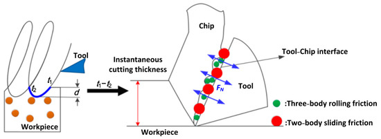
Figure 1.
TPF behavior in SiCp/Al.
Based on the above analysis, the TCI contains three-phase friction (TPF) and is strictly defined as two-body sliding friction, three-body rolling friction, and adhesive friction of matrix. Therefore, the mechanical model is established under the following assumptions [20,21,22]:
- Regardless of the work hardening phenomenon of the material and the lateral flow of the material, the workpiece material is considered isotropic.
- The cutting process is continuous and stable without chipping, and chips do not accumulate on the rake face.
- Ignore the influence of the blunt circle radius of the tool tip when studying the tool trajectory and chip formation.
- In addition to EVC vibration, ignore the existence of other forms of vibration during the cutting process, as well as the impact of vibration on the particle volume fraction.
2.2. EVC Cutting Force Model
The cutting force model reflects the cutting characteristics and mechanical status, and it determines the machining status of the workpiece surface. The cutting force exceeds the yield strength of the material to deform unevenness or extrusion to cause the atom-forming chips to slide out along the rake surface [2]. However, this situation has changed. In EVC, as shown in Figure 2, in a complete ellipse machining trajectory in two dimensions, the cutting force is a variable, and the result is that EVC has frictional flipping, intermittent cutting and the characteristics of variable depth of cut. Meanwhile, the cutting process is more complicated because the cutting tool vibrates in the depth of cut and the cutting direction. The variable cutting depth determines that the force changes during the cutting process, which is why there are different shear zones before and after the EVC friction inversion. The tool relative to the workpiece movement can be obtained from the following Equation (1):
A, B, f, Vp, t, φ are vibration amplitude in x and y axis, vibration frequency, workpiece speed, time variation, and phase difference, respectively. The value of φ in this paper is 90°. Equation (1) provides strong evidence for variable cutting forces in EVC, which is also an important reason for changes in starting force, depth of cut, LT−C, and friction coefficient during EVC. To some extent, the frictional behavior of the tool at TCI can be characterized by cutting speed [7]. The speed of the tool relative to the workpiece can be expressed as:
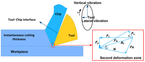
Figure 2.
Friction vector diagram of the second deformation zone in EVC interface friction.
Equations (1) and (2) show that the friction mechanism in EVC is different from conventional turning and is more complicated due to the effects of vibration and tool tip trajectory. The friction force is changed to a time-varying function at time t due to the effects of vibration and tool tip trajectory. In order to model cutting forces, a vector decomposition analysis of the cutting forces is necessary. Due to the lateral vibration, the surface crack of the workpiece contacted by the rake face is deeper and longer than the cutting length, and the actual shear angle increases.
The cutting force mainly comes from deformation and friction, that is, to overcome the resistance of the processed material to elastic deformation, plastic deformation, and the friction of the chip on the rake face. Based on the empirical equation of cutting force, we decompose the cutting force and synthesize the force moment vector diagram as shown in Figure 2. The main average cutting force is equal to the normal stress on the shear plane and can be obtained from Equation (3):
2.3. Tool-Chip Contact Length (LT−C)
LT−C is an important parameter to characterize the tool-chip contact state. Complex negative phenomena such as temperature rise and friction deterioration often occur at the contact interface, and more importantly, stress changes will occur to affect cutting forces [23,24]. The cutting force caused by the third deformation zone is not considered in the modeling of cutting force [25]. Therefore, from the measured cutting force (and corresponding feed force), we subtract the corresponding edge cutting force(and corresponding edge feed force).
In order to accurately analyze different friction behaviors, the LT-C is divided into two parts: (a) the first is the adhesion region, which starts from the edge of the cutter and extends to the middle of the interface length. Therefore, the inner layer of the chip will undergo plastic deformation; (b) the second part is from the middle of the interface length to the point where the chips are separated from the tool face; the LT-C can be obtained from Equation (5):
Equations (5) and (6) both show an interesting phenomenon. Whether in conventional cutting or EVC cutting, there are different friction behaviors at the LT-C. Cutting force Ff can be obtained from SiC particle friction (FS, FR, FM), as shown in Equation (7).
Considering the global Coulomb friction law [1], the overall friction coefficient can be expressed by the Equation (8):
2.4. Normal Force at TCI in EVC (FN)
In conventional cutting, the tool face and the AMCM squeeze each other to produce a balanced normal stress. From a micro perspective, this force is generated by a certain volume fraction of reinforcing particles in the AMCM. As shown in Figure 1, when the load is initially applied, the elastic deformation of some of the reinforced particles resists the load on the blade surface. As the load increases, the volume fraction of the reinforced particles in contact with the tool continuously increases to a critical value. The situation is different when the cutting method is changed from conventional cutting to EVC. Due to two mutually perpendicular vibrations (cutting direction and cutting depth direction), the tip trajectory becomes elliptical, the normal force changes with the change of LT-C, the normal stress distribution is a function of time t, and this can be obtained from the following equation:
The change of shear stress reflects the complex friction change of the tool-chip interface. In EVC cutting SiCp/Al, the shear stress is also a time-varying function of time t. According to Coulomb’s law, the shear stress along the sliding friction zone is as follows:
As shown in Figure 1, it is assumed that the contact and separation times of the tool and the workpiece during a cutting cycle are t1 and t2, respectively, and Lx is the contact length. The above analysis gives us reason to believe that the normal force in EVC can be obtained from the double integral equation of two variables in normal force:
3. Friction Force Prediction at TCI Based on TPF
The TCI friction is composed of the TPI friction component and the TMI friction component. The TPI friction component is a composite friction, and the friction behavior is induced by a certain volume fraction of particles. The two-body sliding friction component produced by particles and the three-body rolling friction caused by particles result in increased tool wear and cutting forces. The TMI friction component can be regarded as the friction generated by conventional cutting, that is, variable cutting deep and cutting processes of aluminum matrix by EVC.
3.1. Prediction of Friction Component at TPI
3.1.1. Prediction of Normal Force in Unit SiC (FN-S)
Reinforced particles are assumed to be circular spheres with radius R and fixed-point angle. Therefore, the stress model of elemental reinforcement analysis can be obtained from Jiang and Dabade et al. [1,13], as shown in Figure 3. P-Q-M is the rake face where the tool contacts a single SiC-rein forced particle. Since P-Q-M is a circular arc, this also provides evidence for sliding friction between the two bodies.
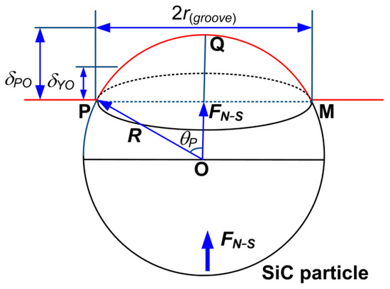
Figure 3.
Particle element analysis.
The normal force of a unit particle can be obtained by the following equation:
δPO is the maximum critical value of relative encroachment of reinforced particles when full plastic deformation occurs on the rake face of the tool.
E* is the compound mode can be obtained from the following Equation (14):
3.1.2. Prediction of Two-Body Sliding Friction Component at TPI (FS)
Based on the two-body sliding friction behavior of the tool-particle interface, the two-body sliding friction component can be given by the following equation.
Assuming that the hard particle volume fraction is evenly distributed over the contact length, the normal stress should be the integral of the LT−C, f(x, qx) is the function of the contact length on the particle volume fraction qx(0 ≤ x ≤ LS). The two-body friction component can be obtained from the following equation:
Combining Equation (6):
3.1.3. Prediction of Three-Body Rolling Friction Component at TPI (FR)
The particles are firmly constrained in the chip when sharpening, causing sliding friction between the two bodies. Three-body rolling friction is caused by deboned particles rolling between the rake face and the Al matrix [26].
Assuming that the hard particle volume fraction is evenly distributed over the LT−C, the normal stress in the EVC should be the integral of the tool-chip contact length (LS ≤ x ≤ LT-C). The two-body friction component can be obtained from the following equation:
μ3 is the friction coefficient of three-body friction [27], which can be obtained from the following equations:
3.2. Prediction of Friction Component at TMI (FM)
The tool-matrix friction component is an important component of cutting force. The rake face of the tool and the SiCp/Al are squeezed. Due to the large pressure between the bottom layer of the chip, the rake face of the tool and the high-temperature adhesive friction, a small part of the material adheres to adhesive wear on the tool. A study proposed by Qi et al. [28], shows that the tool-chip interfaces are divided into sticking and sliding zones. Figure 4 shows a schematic presentation of the contact region of the tool-chip during the EVC. The plane OE and EF represent the sticking region and the sliding region, respectively. The plane OF and DQE are the tool-chip contact interface and the cutting interface, respectively. This friction behavior is changed during the EVC cutting stroke, and only part of the trajectory participates in the cutting process. As shown in Figure 4, the sticking region and the sliding region exist in chip generation behavior instead of tool-chip contact.
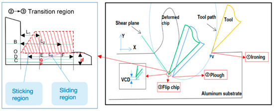
Figure 4.
Friction mechanism of TMI in aluminum matrix.
The elliptical cutting trajectory makes the EVC cutting process go through ironing, ploughing, and finally turning up the chips to form a plastic chip layer. Vibration in the Y direction will produce micro-cutting depth movements to reduce cutting forces. At the same time, coupling with vibration in the X direction will achieve intermittent cutting. The friction component between the tool and matrix can be calculated as an elliptical vibration cutting aluminum material, and it is obtained by the following equation [27]:
τ(tool) is the shear strength of the tool material, L(t) is the length of the active part of the cutting edge, Br is the Briks similarity criterion (Astakhov) that can be calculated by the equation [27]:
ς is the chip compression ratio [29].
The friction component occurring at the TMI is considered to be the performance result of EVC cutting aluminum substrate. The flow stress of the part is affected by the cutting temperature owing to the matrix aluminum’s thermoelectricity. The Johnson-Cook (JC) model was selected as the constitutive relationship model of the matrix aluminum [30], which is given as:
The parameters of the SiCp/Al Johnson-Cook model are shown in Table 1. Variables ε* and T* can be obtained by Equations (27) and (28) [28,31,32]:

Table 1.
Values of J-C equation for these two Aluminum matrices.
4. Results and Discussion
The composite friction characteristic of the tool-chip interface is analyzed and predicted based on Matlab software, and the results are compared with reference [30] to verify the correctness of the model. It is worth noting that different SiC percentage content will result in composites with different density, stiffness and linear expansion coefficient. SiCp/Al is considered to be a difficult-to-machine composite material, possessing complex friction behavior during processing. In this paper, the SiCp/Al composite contains 45% SiC particles with a particle size of 5 μm in a 6061-aluminum matrix, assuming that the silicon carbide-like particles are evenly distributed.
The friction behavior in the machining process will generate a lot of heat, which places demands on the machining tool. Cemented carbide tools have the advantages of high stability and wear resistance. Therefore, the paper chooses the cutting tools of cemented carbide materials with a rake angle of 0° and a relief angle of 7° selected for experimental processing. The Johnson-Cook parameters after debugging are shown in Table 1.
In addition, conditions of EVC cutting were set as follows: cutting width = 1.5 mm, the un-deformed chip thickness s = 0.1 mm, feed rate is set to 0.5 mm/rev, respectively. In order to verify the correctness of the proposed friction model, the value of cutting speed was changed in the range of [50, 650] m/min.
Compared with traditional cutting, EVC can effectively reduce the cutting force due to the characteristics of intermittent cutting in metal machining operations. There are three-phase friction components (FS, FR, FM) in EVC cutting SiCp/Al, which is a complex comprehensive friction. The cutting forces of the experiment and model were simulated and processed based on the TPF theory and results are shown in Figure 5a; Cutting force in conventional machining SiCp/Al is shown in Figure 5b. (Margin of error 25%).
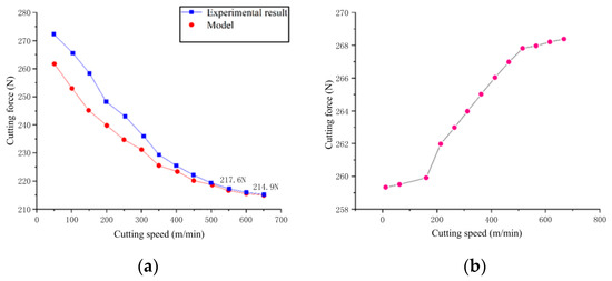
Figure 5.
Changing trend of cutting force. (a) Cutting force prediction in EVC cutting; (b) Cutting force in conventional cutting SiCp/Al.
As shown in Figure 5a, when the cutting speed increases, the cutting force of the model and experiment decreases; when the cutting speed is higher than 450 m/min, the overall cutting force slowly decreases to a minimum value of 214.9 N. When the cutting speed is higher than 550 m/min, the cutting force gradually stabilizes and decreases to 217.6 N. The comparison between the model and the experimental results is consistent, which verifies the reliability of the model in the cutting speed range. In addition, compared with conventional cutting AMCM [30], the prediction model proposed in this paper has effectively reduced the cutting force by 22% (47.3 N). When the cutting speed is lower than 300 m/min, the experimental cutting force is higher than the model cutting force. The reason for this phenomenon is that on the one hand, the cutting tool undergoes a relatively long period of time in the process of ironing-ploughing-turning chips under low-speed cutting. On the other hand, the low-speed cutting dissipates heat faster, and the repeated first cutting phenomenon (cutting under initial friction conditions) will cause the experimental cutting force to exceed the model cutting force. This negative phenomenon will be more obvious at low speeds.
The cutting speed is in the range of [400, 650] m/min, and the average error of the cutting force prediction model is less than 11.4%, which means that the model is suitable for high-speed cutting of aluminum matrix composites. However, the error becomes larger in the vulgar cutting, the reasons being that low-speed intermittent cutting will cause the particle shedding volume fraction to increase, which, in turn, increases the two-body sliding friction and the three-body rolling friction.
The LT−C at TCI is a time-varying function of velocity. As shown in Figure 6 is the tool-chip interface contact length in TCI in the model, the increase in cutting speed is accompanied by a decrease in cutting force, and the LT−C at TCI will also decrease. When the cutting force tends to stabilize, the LT−C between the tool and the chip decreases to a minimum of 0.372 mm. The TPF behavior occurs at the LT−C of the TCI. As the LT−C of the TCI decreases, the space where the friction occurs will be compressed. At this time, the friction force of cutting SiCp/Al by EVC is the smallest, and the cutting force and the interface stress are the smallest.
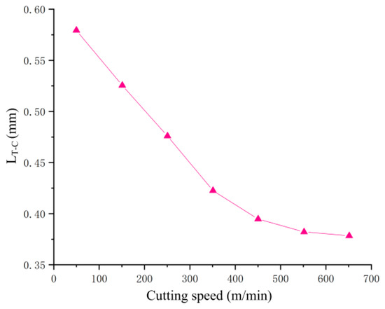
Figure 6.
Tool-chip interface contact length in TCI in the model.
The stress distribution at TCI is an important parameter reflecting the cutting state. In EVC machining, the stress distribution at TCI is a time-varying function of the distance (x) from the cutting point to the tool tip. In this part, the MATLAB is used to simulate the stress distribution at TCI with four different cutting speeds (V = 600 m/min, V = 450 m/min, V = 300 m/min and V = 150 m/min). The results are shown in Figure 7. The average stress showed a downward trend and finally reached the lowest steady state, which also verified the previous prediction of the cutting force model. As shown in Figure 7, the faster the cutting speed, the more obvious the decrease in the distributed stress value.
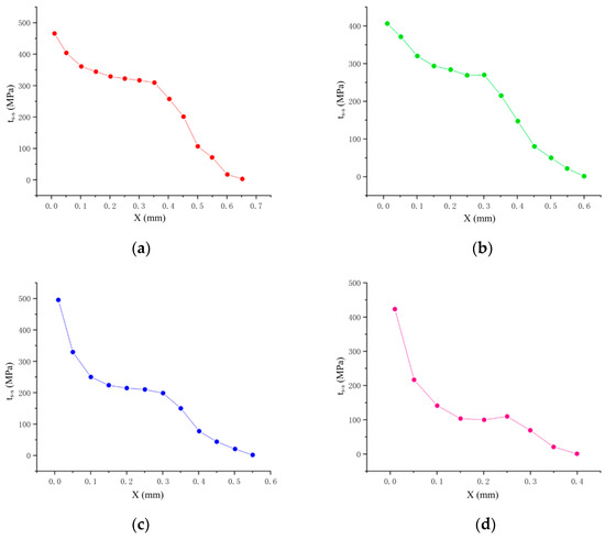
Figure 7.
Distributed stress at the distance from cutting point to tool tip with different speed in the model. (a) V = 150 m/min; (b) V = 300 m/min; (c) V = 450 m/min; (d) V = 600 m/min.
5. Conclusions
Based on TPF theory, this paper establishes a cutting force prediction model for EVC cutting AMCM. The friction components are evaluated at the tool-chip interface (TCI), tool-particle interface (TSI), and tool-matrix (TMI), respectively. In addition, SiCp/Al materials were used to predict and simulate cutting force. The experimental results are consistent with the model. Conclusions as below:
- EVC cutting AMCM can effectively reduce cutting force and improve surface processing quality. Based on the proposed new cutting force prediction model, when the cutting speed is greater than 650 m/min, the cutting force is reduced by 22%, and the TPF stress distribution at the TCI is significantly reduced.
- The cutting speed is in the range of [200, 650] m/min, and the average error of the cutting force prediction model is less than 11.4%, which means that the model is suitable for calculating the cutting force of aluminum matrix composites assisted by elliptical vibration.
- TCI has two-body sliding friction and three-body rolling friction. The intermittent machining characteristics of EVC can effectively reduce the three-body rolling friction and two-body sliding friction of particles. In the model, the total contact length between cutter and chip decreases from 0.57 mm to 0.36 mm, and the stress change reflects the friction characteristics of the cutter chip.
Author Contributions
Investigation, software, writing—original draft, Y.L.; Funding acquisition, project administration, resources, C.W.; Supervision, X.Z.; Conceptualization, writing—review and editing, Y.L., X.Z. and C.W. All authors have read and agreed to the published version of the manuscript.
Funding
This work was supported by the Science and Technology Project of Jilin Provincial Department of Education (JJKH20200310KJ, JJKH20200960KJ).
Institutional Review Board Statement
Not applicable.
Informed Consent Statement
Not applicable.
Data Availability Statement
All data included in this study are available upon request by contact with the author Cui Wang.
Conflicts of Interest
The authors declare no conflict of interest.
Nomenclature
| TCI | Tool-chip interface |
| TPI | Tool-particle interface |
| TMI | Tool-matrix interface |
| k(tool) | Tool material shear stress |
| Vp | Workpiece speed |
| LT−C | The-chip interface contact length |
| TPF | Three-phase friction |
| EVC | Elliptical vibration cutting |
| AMCM | Aluminum matrix composite material |
| Normal stress on the rake face | |
| ζC | Critical volume fraction of particles |
| L(t) | The length of the active part of the cutting edge |
| Ff | Total friction at the tool-chip interface |
| FS | Two body sliding friction component |
| FR | Three-body rolling friction component |
| Cutting force for the tool | |
| FM | Tool-matrix interface friction component |
| Friction on the rake face | |
| FN−S | Element particle normal force |
| The main force of the tool | |
| v1, v2 | Poisson’s ratio of cutters and particles |
| V | Conventional cutting speed |
| xt,zt | The tool tip positions at time t |
| θP | Particle fixed angle |
| ϕC | Shear angle |
| Shear force | |
| ε* | Dimensionless strain rate |
| T* | The homologous temperature |
| p | constant |
| ε | Index coefficient |
| R | Define particle radius |
| Ht | Tool material hardness |
| A, B | Vibration amplitude in x and y axis |
| α* | Normal flank angle |
| r | Cutting edge arc radius |
| r(groove) | Groove size radius |
| f | Vibration frequency |
| β | Friction angle |
| α | Tool rake angle |
| ξS | Particle volume fraction |
| E* | Compound mold |
| σy(tool) | Tool yield strength |
| G(t) | Function of cutting speed on normal stress distribution |
| F(t) | Function of cutting speed on shear stress distribution |
| η | Percentage of particles with three-body rolling friction |
| Back cutting force vertical cutting direction | |
| E1, E2 | Tool and particle modulus |
| δPO | Maximum threshold of relative particle invasion |
| μ,μ3 | Average and three-body rolling friction coefficient |
| λ | Percentage of particles with two-body sliding friction |
| P(t) | Function of cutting time on tool-chip contact length |
| Normal force on vertical shear plane (tool-chip interface) | |
| LS | Sliding friction dominant tool-chip interface contact length |
| f(x,qx) | Function of tool-chip contact length |
| LT | The length of rolling friction and sticking friction |
| τS | The material flow stress |
References
- Dabade, U.A.; Dapkekar, D.; Joshi, S.S. Modeling of chip–tool interface friction to predict cutting forces in machining of Al/SiCp composites. Int. J. Mach. Tools Manuf. 2009, 49, 690–700. [Google Scholar] [CrossRef]
- Hu, Y.; Wu, T.; Guo, Y.; Wang, W.; Song, M.; Qian, L.; Zhao, H.; Wang, M. Effects of T6 treatment, tensile temperature, and mass fraction of SiC on the mechanical properties of SiCp/6061Al composites. Materials 2019, 12, 1602. [Google Scholar] [CrossRef] [Green Version]
- Wang, B.; Qu, S.; Li, X. Effect of the different high volume fraction of SiC particles on the junction of bismuthate glass-SiCp/Al composite. Scanning 2018, 2018, 1–10. [Google Scholar] [CrossRef] [PubMed] [Green Version]
- Shamoto, E.; Moriwaki, T. Study on elliptical vibration cutting. CIRP Ann. 1994, 43, 35–38. [Google Scholar] [CrossRef]
- Guo, P.; Ehmann, K.F. Development of a tertiary motion generator for elliptical vibration texturing. Precis. Eng. 2013, 37, 364–371. [Google Scholar] [CrossRef]
- Xun, L.; Zhang, D. Ultrasonic elliptical vibration transducer driven by single actuator and its application in precision cutting. J. Mater. Process. Technol. 2006, 180, 91–95. [Google Scholar]
- Zhang, X.; Sui, H.; Zhang, D.; Jiang, X. Study on the separation effect of high-speed ultrasonic vibration cutting. Ultrasonics 2018, 87, 166–181. [Google Scholar] [CrossRef]
- Pramanik, A.; Zhang, L.C.; Arsecularatne, J.A. Prediction of cutting forces in machining of metal matrix composites. Int. J. Mach. Tools Manuf. 2006, 46, 1795–1803. [Google Scholar] [CrossRef] [Green Version]
- Balaji, A.K.; Sreeram, G.; Jawahir, I.S.; Lenz, E. The effects of cutting tool thermal conductivity on tool-chip contact length and cyclic chip formation in machining with grooved tools. CIRP Ann. 1999, 48, 33–38. [Google Scholar] [CrossRef]
- Chandrasekaran, H.; Kapoor, D.V. Photoelastic analysis of tool-chip interface stresses. J. Eng. Ind. 1965, 87, 495–502. [Google Scholar] [CrossRef]
- Takahiro, S.; Eiji, U. Friction Characteristics on tool face in metal machining. J. Jpn. Soc. Precis. Eng. 1973, 39, 966–972. [Google Scholar]
- Childs, T.; Maekawa, K. Computer-aided simulation and experimental studies of chip flow and tool wear in the turning of low alloy steels by cemented carbide tools. Wear 1990, 139, 235–250. [Google Scholar] [CrossRef]
- Jiang, J.; Sheng, F.; Ren, F. Modelling of two-body abrasive wear under multiple contact conditions. Wear 1998, 217, 35–45. [Google Scholar] [CrossRef]
- Rakesh, M.; Datta, S. Effects of cutting speed on chip characteristics and tool wear mechanisms during dry machining of Inconel 718 using uncoated WC tool. Arab. J. Sci. Eng. 2019, 44, 7423–7440. [Google Scholar] [CrossRef]
- Lee, T.H. Development of a theoretical model to predict cutting forces for hard machining. Int. J. Precis. Eng. Manuf. 2011, 12, 775–782. [Google Scholar] [CrossRef]
- Sikder, S.; Kishawy, H.A. Analytical model for force prediction when machining metal matrix composite. Int. J. Mech. Sci. 2012, 59, 95–103. [Google Scholar] [CrossRef]
- Ghandehariun, A.; Kishawy, H.; Balazinski, M. On machining modeling of metal matrix composites: A novel comprehensive constitutive equation. Int. J. Mech. Sci. 2016, 107, 235–241. [Google Scholar] [CrossRef]
- Kim, B.G.; Dong, S.L.; Su, D.P. Effects of thermal processing on thermal expansion coefficient of a 50 vol.% SiCp/Al composite. Mater. Chem. Phys. 2001, 72, 42–47. [Google Scholar] [CrossRef]
- Huang, C.W.; Aoh, J.N. Friction stir processing of copper-coated SiC particulate-reinforced aluminum matrix composite. Materials 2018, 11, 599. [Google Scholar] [CrossRef] [Green Version]
- Lu, M.; Chen, B.; Lin, J.; Zhao, D.; Zhou, J.; Yi, A.; Zhu, Z. Friction modeling of tool-chip interface based on shear-slip theory for vibration assisted swing cutting. J. Manuf. Process. 2020, 55, 240–248. [Google Scholar] [CrossRef]
- Barelli, F.; Wagner, V.; Laheurte, R.; Dessein, G.; Darnis, P.; Cahuc, O.; Mousseigne, M. Orthogonal cutting of TA6V alloys with chamfered tools: Analysis of tool-chip contact lengths. Proc. Inst. Mech. Eng. Part B J. Eng. Manuf. 2017, 231, 2384–2395. [Google Scholar] [CrossRef]
- Toshiyuki, O.; Mamoru, H. Ultrasonic-assisted incremental microforming of thin shell pyramids of metallic foil. Micromachines 2017, 8, 142. [Google Scholar]
- Ren, C.; Ke, Z.; Chen, G.; Wu, J. Modeling of tool-chip contact length for orthogonal cutting of Ti-6Al-4V alloy considering segmented chip formation. Trans. Tianjin Univ. 2016, 22, 525–535. [Google Scholar] [CrossRef]
- Duan, C.; Sun, W.; Fu, C.; Fangyuan, Z. Modeling and simulation of tool-chip interface friction in cutting Al/SiCp composites based on a three-phase friction Model. Int. J. Mech. Sci. 2018, 142–143, 384–396. [Google Scholar] [CrossRef]
- Ozlu, E.; Molinari, A.; Budak, E. Two-zone analytical contact model applied to orthogonal cutting. Mach. Sci. Technol. 2010, 14, 323–343. [Google Scholar] [CrossRef]
- Goddard, J.; Wilman, H. A theory of friction and wear during the abrasion of metals. Wear 1962, 5, 114–135. [Google Scholar] [CrossRef]
- Astakhov, V.P.; Xiao, X. A methodology for practical cutting force evaluation based on the energy spent in the cutting system. Mach. Sci. Technol. 2008, 12, 325–347. [Google Scholar] [CrossRef]
- Qi, H.S.; Mills, B. Modelling of the dynamic tool–chip interface in metal cutting. J. Mater. Process. Technol. 2003, 138, 201–207. [Google Scholar] [CrossRef]
- Astakhov, V.P. The assessment of cutting tool wear. Int. J. Mach. Tools Manuf. 2004, 44, 637–647. [Google Scholar] [CrossRef]
- Johnson, G.R.; Cook, W.H. A constitutive model and data for metals subjected to large strains, high strain rates and high temperatures. Eng. Fract. Mech. 1983, 21, 541–548. [Google Scholar]
- Atkins, A.G. Toughness and oblique metalcutting. J. Manuf. Sci. Eng. 2006, 128, 775–786. [Google Scholar] [CrossRef]
- Zhu, X.; Liu, Y.; Zhang, J.; Wang, K.; Kong, H. Ultrasonic-assisted electrochemical drill-grinding of small holes with high-quality. J. Adv. Res. 2020, 23, 151–161. [Google Scholar] [CrossRef] [PubMed]
Publisher’s Note: MDPI stays neutral with regard to jurisdictional claims in published maps and institutional affiliations. |
© 2021 by the authors. Licensee MDPI, Basel, Switzerland. This article is an open access article distributed under the terms and conditions of the Creative Commons Attribution (CC BY) license (https://creativecommons.org/licenses/by/4.0/).