Abstract
To improve the processing efficiency and the surface properties of C61900 Cu alloy, a gradient Cu-Ti film with a Ti/Cu atom ratio of 7:1, 7:4, and 1:2 was pre-fabricated by the unbalanced magnetron sputtering process and then nitrided by thermos plasma nitriding. The phase structure, elemental composition, and morphology of the modified surface were characterized, and the mechanical properties, including the wear resistance and adhesion properties, were examined. Combining calculation by the first principle method with thermodynamic analysis, the microstructural formation and phase composition of the Cu-Ti-N system were investigated to reveal the mechanism of improved wear resistance, which indicated the possible formation of various Cu-Ti intermetallics and Ti-N compounds. The Al in the C61900 Cu substrate also participated in the generation of the AlCu2Ti compound, which is a ductile phase with good hardness and elastic modulus. Based on the results of a mechanical properties test, it was concluded that an optimized layer structure for the multi-phase coating should include Ti-N compounds as the surface layer and Cu-Ti intermetallics as the intermediate layer.
1. Introduction
The C61900 aluminum bronze alloy has been widely applied in the electronics, electrical, automotive, aviation, and astronautics fields. However, the deficient wear resistance of Cu alloys makes surface modification necessary [1,2,3,4], especially for Cu alloy devices used in harsh environments. Plasma nitriding of titanium alloys has been investigated to fabricate a titanium nitride layer for its excellent wear resistance and high hardness [5,6,7]. However, the disparity between the hard coating and the soft Cu substrate results in low adhesion [2,5]. To solve this problem, a gradient layer is proposed to achieve a higher interface strength by metallurgical bonding in thermal diffusion [8]. Specifically, an intermediate Cu-Ti intermetallic layer is regarded as the most appropriate candidate to be the transition medium between the titanium nitride layer and the Cu substrate [9,10,11], where the formation of a thin TiN and Cu3Ti3O layer contributes to the improvement of wear resistance by plasma nitriding [12]. In addition, the multi-phase coating containing nanocrystalline or micro grains, such as TiN/TiAl and TiN/TiCN, also enhances ductility [13,14,15]. Fouquent et al. investigated the plasma-assisted nitriding process on Ti-6Al-4V alloy, and they found that the main phases of the nitrided layer were δ-TiN, ε-Ti2N and the solid solution of N atoms dissolved in α-Ti [16]. In our previous studies [17,18], it was reported that the different Cu-Ti intermetallics of varying mechanical properties might form during the thermal diffusion process [19,20], and their formation was affected by the addition of N atoms [21,22,23,24,25]. From the Ti-N phase diagram, it can be seen that δ-TiN (Fm3m), δ′-Ti2N (I41/amd), ε-Ti2N (P42/mnm), α-Ti, and β-Ti of nitrogen-containing solid solutions all exist in this system, where the solubility of N atoms in α-Ti is 23 at.% [26]. To be mentioned, the interaction between Al and Cu, Al and Ti during the thermos plasma nitriding process must be considered due to the high content of the Al atom in the C61900 Cu alloy (8.95 wt.%). The projection in the liquid phase and the isothermal section of the Al-Cu-Ti ternary phase diagram at 500 °C shows that the AlCu2Ti phase can form in a variable composition interval [27]. The formation mechanism of AlCu2Ti in plasma nitriding of Cu-Ti films on C61900 Cu alloy is attributed to the elemental Al diffusion process in the C61900 Cu alloy and the Ti atoms in the film layer. However, the above mentioned researches mainly focused on the experimental results of the microstructure and the optimal mechanical properties in the series of experiments. The design and control of the phase compositions based on the first principle study have been rarely explored. Actually, both the phase stability and the mechanical properties of the Ti-N compounds and the Cu-Ti intermetallics have been investigated [28,29,30], but there are still few reports on the Ti-Cu-N and Ti-Al-Cu ternary systems that industry demands.
In the present study, surface modification of C61900 Cu alloy by thermos plasma nitriding of the prefabricated Cu-Ti film was undertaken, and the wear resistance was evaluated experimentally. Combining the calculation by the first principle method and thermodynamic analysis, the microstructure formation and phase composition of the Cu-Ti-N and Al-Cu-Ti systems were investigated to reveal the mechanism of the improved wear resistance, where the formation potential, phase stability, and mechanical properties of the Ti-N nitride compounds and Al-Cu-Ti compounds and the essence of the improved wear resistance of the multi-phases coating were explored. The conclusions could provide useful instructions for the surface modification of C61900 alloys by the combination of magnetron sputtering and plasma nitriding processes.
2. Materials and Methods
A φ20 mm C61900 aluminum bronze bar was sliced into φ20 × 4.5 mm sections for the surface modification process by magnetron sputtering and subsequent thermos plasma nitriding. The chemical composition of the C61900 alloy is listed in Table 1, which shows that it is composed of copper, aluminum, iron, etc. The obtained substrates were first treated for solid solution by water quenching after heating at 930 °C for 2 h. The Cu-Ti gradient films of different compositions were firstly fabricated with the UDP450 closed field unbalanced magnetron sputtering equipment, and the processing parameters are listed in Table 2 and Table 3. The subsequent thermos plasma nitriding of the obtained films was undertaken to generate a multi-phase coating in a homemade pulsed plasma multicomponent infiltration furnace (LDMC-30 kW), with a nitrogen and hydrogen gas flow rate ratio of 0.3:0.1 L/min to generate a high nitrogen phase. Detailed information on the magnetron sputtering and plasma nitriding processes can be found in previous studies [31,32].

Table 1.
The chemical composition of C61900 Cu alloy (wt.%).

Table 2.
The fixed parameters for the magnetron sputtering process.

Table 3.
The parameters for the fabricated films with different Cu, Ti contents.
The phase structures of the gradient Cu-Ti films and the multi-phase coating were characterized by the D/max-rB rotary anode X-ray diffractometer, and the CuKα target was applied at a voltage of 40 kV and current of 30 mA, with a scanning range from 20°–100° and scanning speed of 5°/min. The XRD patterns were compared with the standard PDF (ASTM) card to complete the phase structure calibration. The phase structures of the multi-phase coating were also analyzed by grazing incidence X-ray diffraction at an incident angle of 1°. The surface morphology and cross-sectional morphology of the pre-fabricated coatings were examined by a scanning electron microscope (SEM, SUPRA 55 SAPPHIRE), equipped with an energy dispersive spectrometer (EDS).
The hardness and elastic modulus of the multi-phase coatings were measured by a nano-indenter, where the continuous stiffness measurement (CSM) mode was applied at continuous indentation depths. The scratching test was then performed on the MFT-4000 multifunctional material surface performance tester to evaluate the adhesion of the coating. The device was continuously loaded by a diamond scriber in automatic mode at a loading speed of 100 N/min and maximum load of 100 N, where the sensor recorded the acoustic emission signals and the friction force signals. When the film layer peeled off, the critical load of the binding force between the coating and the substrate could be obtained. In addition, the pin-on-disk wear performance was measured against a WC ball of 5 mm in diameter. The test was carried out under dry friction conditions with a positive pressure of 4 N, a rotating speed of 200 r/min and a test time of 1800 s. A Wyko NT8000 white light interferometer was used to measure the cross-sectional profiles of the worn tracks, by which the volume wear rate was calculated [31].
For the first principle calculation, the K point and kinetic energy cut-off were optimized to make the energy difference between the two settings less than 0.01 eV. After the convergence test, the plane wave truncation energy was set to be 600.0 eV. The K points of the Brillouin zones of TiN0.3, Ti2N (P42/mnm), Ti2N (I41/amdz), and TiN were set to be 3 × 3 × 2, 7 × 7 × 11, 6 × 6 × 4, and 12 × 12 × 12, respectively, and the K points in the Brillouin regions of the AlCu2Ti phase, the Al3Cu8Ti5 phase, and the Al5Cu8Ti3 phase were set to be 8 × 8 × 8. In addition, the phases of the Ti(1−x)MxN system were also investigated by the Materials Visualizer module in Materials Studio, where the TiN primitive cell was firstly established and the Ti atom in the TiN primitive cell was replaced by M (M = Al, Fe, Cu) atom to establish the crystal structure model. Then, the established crystal structure was acquired by taking the asymmetric structure.
3. Results and Discussion
3.1. Microstructure and Phase Compositions of the Multi-Phase Coatings
The compositions of the fabricated Cu-Ti films on the surface of the C61900 Cu alloy measured by EDS are listed in Table 4. The Cu-Ti film with Ti/Cu atomic ratios was close to 7:1, 7:4, and 1:2 for F1, F2, and F3. Figure 1 shows XRD patterns of the Cu-Ti films obtained on the C61900 Cu alloy. The composed phases differed depending on the Ti/Cu atomic ratio. Specifically, the crystalline phases of the F1 film were mainly β-Ti phase, Ti2Cu phase, and a trace of α-Ti phase, as shown in Figure 1a. The intense peak at 2θ = 38.2° was from β-Ti rather than α-Ti, where the formation of β-Ti phase was promoted by the Cu substrate for the same body-centered cubic structure. In comparison, the main phases of the F2 film were Ti2Cu and a small amount of CuTi phase, while the F3 film contained no crystalline Cu-Ti phase, as shown in Figure 1b,c, respectively. The surface morphology of the Cu-Ti films also changed, as shown in Figure 1d–f, where the F1 film was smooth with uniform particles, and the F2 and F3 films were much finer.

Table 4.
The composition and thickness of the Cu-Ti films fabricated by magnetron sputtering on C61900 Cu alloys.
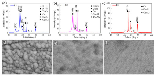
Figure 1.
XRD results and SEM images of the Cu-Ti films on C61900 Cu alloy: (a,d) for F1, (b,e) for F2, (c,f) for F3.
The three Cu-Ti films prepared on the C61900 Cu alloy were then treated by plasma nitriding at 650 °C for 4 h. Except for the Cu-Ti intermetallics and Ti-N compounds, an AlCu2Ti phase also formed after plasma nitriding, as shown in Figure 2a. The grazing incidence XRD of the Cu-Ti films after nitriding at 650 °C indicated that the TiN and TiN0.3 phases existed in the outmost layer, and the diffraction peak of the Cu3Ti and AlTi phases in the F2 film coated surface was enhanced simultaneously after nitriding at 650 °C for 4 h, as shown in Figure 2b.
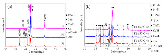
Figure 2.
(a) XRD results of the Cu-Ti films after plasma nitriding at 650 °C for 4 h, (b) GIXRD results of the Cu-Ti films after plasma nitriding at 650 °C for 4 h.
After nitriding at 650 °C for 4 h, the surface morphology of the Cu-Ti films changed, as shown in Figure 3. The discontinuous white Fe-rich phase formed on the surface, which was attributed to the sputtering of the Fe element in the hollow cathode net, as indicated by the EDS results for the selected area. For F2 and F3 films, the size of the Fe-rich phase particles became larger (about 2–3 μm). In addition, no Cu element for F1 film after nitriding was detected, and the Cu content on the surface of F3 film decreased.
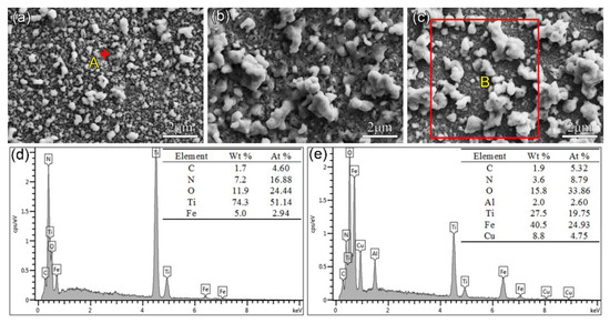
Figure 3.
Surface morphology and the EDS results for the Cu-Ti film on C61900 Cu alloy after plasma nitriding at 650 °C for 4 h: (a) F1, (b) F2, (c) F3, (d) EDS result for point A in (a), (e) EDS result for region B in (c).
3.2. Mechanical Properties of the Multi-Phases Coatings
The change in the hardness and elastic modulus of C61900 Cu alloy with increasing indented depth is shown in Figure 4. The hardness of the unmodified C61900 Cu alloy substrate increased rapidly up to 6 GPa and then decreased gradually with the growth of depth, which was kept constant at 3 GPa. The elastic modulus of the C61900 Cu alloy shared the same trend until it reached about 125 GPa. The increase in the early hardness and modulus was attributed to the size effect and work hardening effect. For the multi-phase coatings, the hardness of the modified layer at 0–300 nm from the surface was lower than the C61900 Cu alloy for the F1 and F3 films, and the hardness of the nitrided F2 film was the highest at this stage, which was dependent on the particle size and the surface morphology, as indicated in Figure 3. The hardness and modulus for the nitrided F1 and F2 films followed the same changing trend. The maximum hardness value of nitrided F1 film and F2 film reached 5.5 GPa and 4 GPa, respectively. A critical indented depth of about 500 nm existed, where the hardness and modulus of the F1 film after nitriding were highest when the depth was over 500 nm.
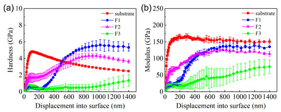
Figure 4.
Surface hardness and elastic modulus of the Cu substrate and three films after plasma nitriding at 650 °C for 4 h with increasing displacement: (a) hardness, (b) elastic modulus.
Figure 5 shows the morphology of the cross-sections and the EDS results after nitriding at 650 °C for 4 h. The thickness of the F1, F2, and F3 films after nitriding was 7 μm, 6 μm, and 3 μm, respectively. The Ti content remained at a high level only in a range of about 650 nm from the surface for F1 and F2. Combined with the results of EDS and GIXRD, it was found that the multi-phase coatings consisted of a nitride layer as the outmost surface and a thicker intermediate layer of Cu-Ti and AlCu2Ti. In addition, a discontinuous Cu-rich layer appeared in the multi-phase coating of the nitrided F3 film. Due to the strong affinity between Ti and N, the Ti-N compounds formed on the surface after nitriding under high nitrogen content, so Cu accumulated in the subsurface.
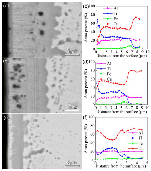
Figure 5.
Morphology of the cross-section (back-scattered electron image) and EDS results for the Cu-Ti films after plasma nitriding at 650 °C for 4 h: (a) and (b) for F1, (c) and (d) for F2, (e) and (f) for F3.
The friction and wear properties of the C61900 Cu alloy and the modified surface were evaluated. The surface topography of the worn track and the friction coefficient of the C61900 Cu substrate against the WC ball showed serious surface wear with a deep worn track of 12.7 μm (as displayed in our previous work [18]). As shown in Figure 6a, the friction coefficient of the C61900 Cu alloy was stable at 0.16. In comparison, the friction coefficient of the modified layer of nitrided F2 film and F3 film decreases to 0.1, while the friction coefficient of the nitrided F1 film slowly increased from 0.05 to 0.3. In addition, the wear rates of the F1, F2, and F3 films after plasma nitriding were 3.6 × 10⁻¹⁵ m3/Nm, 1.0 × 10⁻¹⁵ m3/Nm, and 3.8 × 10⁻¹⁴ m3/Nm, respectively, which were 98%, 99.5%, and 79% lower than the matrix, respectively, as shown in Figure 6b.
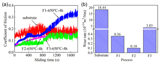
Figure 6.
The friction coefficient and wear rate of C61900 Cu alloy and the modified surface: (a) friction coefficient, (b) wear rate.
The surface morphologies and cross-sectional profiles of worn tracks after nitriding at 650 °C for 4 h showed that peeling of the hard coating was induced during the wear test. The worn depth and width of F1 film reached 1.5 μm and 200 μm, respectively, as shown in Figure 7a,b. For the nitrided F2 film, only slight scratch marks remained on the modified layer, with a depth and width of only 0.7 μm and 150 μm, respectively. However, the depth and width of the abrasive groove for the nitrided F3 film reached 4.3 μm and 400 μm, respectively. The EDS results for the A-F region in Figure 7 are listed in Table 5. The high O content indicates that oxidation occurred during the wear process. For the nitrided F1 film and F2 film, the N atoms in region B and region D reached 15.9 at.% and 6.7 at.%, respectively, which indicates that the nitrides formed, and this can effectively improve the wear resistance.
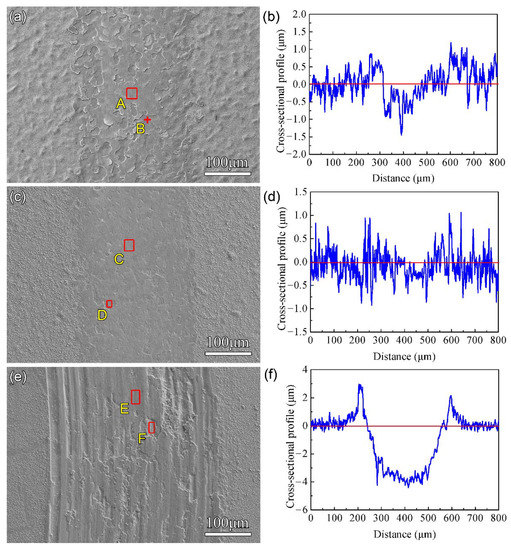
Figure 7.
The surface morphology and cross-sectional profile of the worn tracks after plasma nitriding at 650 °C for 4 h: (a,b) for F1 film, (c,d) for F2 film, (e,f) for F3 film.

Table 5.
Semi-quantitative EDS results for areas A–E in Figure 7 (at.%).
The acoustic signal curves and friction force curves of the multi-phase coatings on the C61900 Cu alloy are shown in Figure 8. The friction force increased slowly as the load grew to be about 18 N, and no change in the acoustic signal was detected. During the scratching test of the modified surfaces, the load continuously increased. When the normal load increased to the critical value, not only did a sudden change in the friction force occur, but also a sharp increase in the acoustic signal could be detected due to the fracture or separation of the multi-phase coatings. Thus, the critical load of failure could be obtained, which was dependent on the coating thickness, the residual stress, and the mechanical properties of the substrate (e.g., hardness), as well as the test parameters (e.g., ram radius and sliding speed) [33,34]. With the further increase in the load to 45 N, a spike in the acoustic signal was induced at the critical load, indicating that the brittle coating was broken, as shown in Figure 8a. For the nitrided F2 film, the critical load for the multi-phase coating was 38 N, and the substrate was gradually exposed at a distance of about 1 mm from the starting point, as shown in Figure 8b,c. Similarly, for the nitrided F3 film, the friction force gradually increased with the load to about 17 N, and no change in the acoustic signal appeared until the load increased to the critical load of about 44 N. The friction force curve also fluctuated at the intensity peak of the acoustic signal, as shown in Figure 8d.
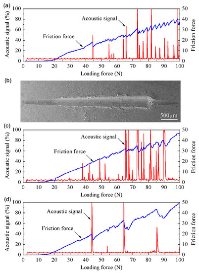
Figure 8.
The scratching curves and typical surface morphology of C61900 Cu alloy after plasma nitriding at 650 °C for 4 h: (a) the friction force and acoustic signal curve of F1 film, (b) the surface morphology of the scratching grooves for F2 film, (c) the friction force and acoustic signal curve of F2 film, (d) the friction force and acoustic signal curve of F3 film.
It is well known that the wear resistance is closely related to the surface hardness and elastic modulus. In the present work, the wear resistances of the three types of coatings were all improved, although the measured surface hardness of the modified coatings was even lower than that of the Cu substrate at the initial indentation depth (see Figure 4a). The measured average hardness by the indentation could not reflect the wear resistance appropriately. In addition, the scratching force as well as the acoustic emission signal always showed some fluctuation. Therefore, it is of great importance to study the mechanical properties of the possible formed phases by first principle calculations to provide basic knowledge on the obtained surface properties of the multi-phase coatings.
3.3. The Phase Formation Mechanism and Mechanical Properties
The structure of α-TiN0.3 can be regarded as a solid solution of N atoms in the close-packed hexagonal structure of α-Ti. A 3 × 3 × 2 supercell is built based on the microstructure of α-Ti, where 11 nitrogen atoms occupy the octahedral space in the Ti36 super crystal cell without changing the lattice geometry of Ti36, forming Ti36N11 to describe the α-TiN0.3 phase. The crystal structure models of the Ti-N system are shown in Figure 9.

Figure 9.
The crystal structures of typical Ti-N compounds, with the gray balls and blue balls representing Ti and N, respectively.
The Gibbs free energy of TiN, ε-Ti2N, and TiN0.3 between 900 K and 1100 K could be obtained, as shown in Figure 10. The negative Gibbs free energy of these three phases firstly indicated their possible formation; the calculated lattice parameters and the formation enthalpy of the Ti-N intermetallic compounds are listed in Table 6 and compared with the existing calculation results. The results showed that the higher the N content, the greater the formation enthalpy of the Ti-N compound and the better the thermodynamic stability, namely TiN > Ti2N(P42/mnm) > TiN0.3. The calculated elastic constants Cij of the Ti-N intermetallic compounds, as shown in Table 7, indicate that all Ti-N compounds are mechanically stable.
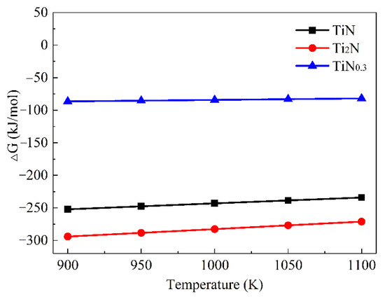
Figure 10.
Dependence of the Gibbs free energy (∆G) on the temperature (T) for the Ti-N compounds.

Table 6.
The calculated lattice parameters (a, b, and c in nm) of the Ti-N compounds by the first principle, compared with other theoretical results.

Table 7.
The calculated elastic constants for Ti-N compounds.
The elastic constants were applied to calculate the bulk modulus (B), shear modulus (G), Young’s modulus (E), and Poisson’s ratio (υ) of the possible phases, as shown in Table 8. The Vickers hardness for the analyzed phases in the present work can also be obtained based on the following equation [37],
where K = G/B is Pugh’s ratio.

Table 8.
The calculated bulk modulus B (GPa), shear modulus G (GPa), Young’s modulus E (GPa), Poisson’s ratio υ, Pugh’s ratio G/B, Cauchy pressure C12–C44, and Vickers hardness HV for Ti-N compounds.
It can be seen that the calculated elastic modulus was in good agreement with the previous literature. The shear modulus was positively correlated with the phase stability, so Ti2N (I41/amdz) had poor stability for the lowest shear modulus. The volume modulus (B), shear modulus (G), Young’s modulus (E), and Vickers hardness (HV) of other Ti-N compounds all met the relationship of TiN > Ti2N(P42/mnm) > TiN0.3. That is, with the increase in N content, both the modulus and Vickers hardness increased and were higher than those of the Cu-Ti intermetallics. The brittleness and toughness of the Ti-N compounds were also evaluated by the G/B ratio and Cauchy pressure C12–C44 of Pettifor’s principle [38,39], which indicated that the TiN, Ti2N (P42/mnm), and TiN0.3 all belong to brittle compounds. Therefore, the surface modification layer of C61900 Cu alloy should be designed with the hard Ti-N compound as the outmost layer and the Cu-Ti intermetallics as the middle layer for the compromising hardness.
The properties of the AlCu2Ti, Al3Cu8Ti5, and Al5Cu8Ti3 were also investigated by first-principle calculation. The crystal structures of the four phases are shown in Figure 11. An Al atom in the AlCu2Ti phase structure is replaced by a Ti atom to form the crystal structure of the Al3Cu8Ti5 phase. Similarly, the formation mechanism of the Al5Cu8Ti3 crystal structure is attributed to the replacement of the Ti atom with an Al atom in the AlCu2Ti crystal structure. Table 9 shows the calculated lattice parameters and the formation enthalpy of the AlCu2Ti, Al3Cu8Ti5, and Al5Cu8Ti3 phases, compared with other, related values in the literature [40,41]. The calculated lattice constants are close to those in the literature with a deviation of less than 1%. The negative formation enthalpies of AlCu2Ti, Al3Cu8Ti5, and Al5Cu8Ti3 intermetallics indicate the thermodynamic stability of the above phases, where the lowest formation enthalpy of the AlCu2Ti phase indicates its best stability. In addition to the thermodynamic stability, the mechanical stability was also achieved to judge whether a phase is formed. The calculated elastic constants Cij of AlCu2Ti, Al3Cu8Ti5, and Al5Cu8Ti3 are shown in Table 10, which shows that all three phases have mechanical stability.

Figure 11.
The crystal structures of AlCu2Ti, Al3Cu8Ti5, and Al5Cu8Ti3, with the pink balls, the blue balls and the yellow balls representing Cu, Ti, and Al, respectively.

Table 9.
The calculated lattice parameters (a, b, and c in nm) for the Al-Cu-Ti intermetallics, compared with the other theoretical results.

Table 10.
The calculated elastic constants for the Al-Cu-Ti intermetallics.
The AlCu2Ti, Al3Cu8Ti5, and Al5Cu8Ti3 intermetallics are all thermodynamically and mechanically stable, which might be formed within a certain range of elemental composition. The elastic constants were applied to calculate the volume modulus (B), shear modulus (G), Young’s modulus (E), and Poisson’s ratio (υ). The hardness, brittleness, and toughness of these intermetallics were evaluated. The mechanical properties of AlCu2Ti, Al3Cu8Ti5, and Al5Cu8Ti3 are listed in Table 11. The calculated volume modulus is in good agreement with the literature [40,41], and the hardness of the AlCu2Ti phase reached 6.75 GPa. According to the criterion for determining toughness and brittleness based on the G/B values, the AlCu2Ti, Al3Cu8Ti5, and Al5Cu8Ti3 were all ductile phases. As a ductile material with high elastic modulus and hardness, the AlCu2Ti phase is a good candidate in applications as a wear-resisting material.

Table 11.
The calculated bulk modulus B (GPa), shear modulus G (GPa), Young’s modulus E (GPa), Poisson’s ratio υ, Pugh’s ratio G/B, Cauchy pressure C12–C44, and Vickers hardness HV for the Al-Cu-Ti intermetallics.
The effect of N on the formation enthalpy of β-Cu4Ti, CuTi, Cu3Ti2, and Ti2Cu is shown in Figure 12. It can be seen that the solid solution energy of the Cu-Ti intermetallics firstly dropped and then increased with further growth in N content. Therefore, the addition of N atoms affected system stability and had a significant influence on the formation enthalpy, which provided good theoretical guidance for the nitriding of Cu-Ti intermetallics. To evaluate the influence of the M atom (M = Al, Fe, Cu), the Ti(1−x)MxN system was also investigated. Table 12 shows the lattice parameters and formation enthalpy of Ti(1−x)MxN, which were set and calculated at the K-point of Ti(1−x)MxN in the Brillouin zone. The relationship between the phase formation enthalpy of Ti(1−x)MxN and the content of M is shown in Figure 12b. It can be seen that the Al, Fe and Cu in TiN had different influences on formation enthalpy, and high thermodynamic stability could be achieved for the Ti(1−x)MxN system when the content of element M was in a certain range. Specifically, when the Ti atom was totally replaced by the Fe atom, the formed FeN structure tended to be unstable. When the Cu atom replaced the Ti atom to form the Ti(1−x)MxN phase, the formation enthalpy increased rapidly, and the structure became unstable when x ≥ 0.75. According to previous research works [42,43], the TiNx grain boundary is isolated and the growth of TiN is hindered when the Cu content reaches a certain value.
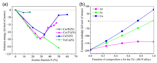
Figure 12.
(a) The change in the solution energy for N in Cu-Ti intermetallics; (b) the formation enthalpy of Ti(1−x)MxN.

Table 12.
The calculated lattice parameters (a, b, and c in nm) of Ti-N intermetallics.
The calculated elastic constants Cij of Ti(1−x)MxN are shown in Table 13. It can be seen that all types of Ti(1−x)MxN compounds are mechanically stable except for FeN. However, the thermodynamic and mechanical stability change when x ≥ 0.75, which indicates that the phases easily decompose or react with other substances, although the structure could form in the non-equilibrium process when the Cu content in Ti(1−x)MxN phase is high enough.

Table 13.
The calculated elastic constants for Ti(1−x)MxN intermetallics.
The volume modulus, shear modulus, Young’s modulus, Poisson’s ratio, G/B value, Cauchy-pressure, and Vickers hardness of Ti(1−x)MxN were also calculated, as shown in Table 14. It can be seen that the volume modulus, shear modulus, elastic modulus, and hardness all decreased with the increasing content of Fe and Cu. When the intermetallics contained the element Al, the volume modulus decreased while the shear modulus increased, which means that both Young’s modulus and hardness grew. The shear modulus was positively correlated with phase stability, which was consistent with the changing minimum enthalpy and high stability when Ti atoms were replaced by Al atoms.

Table 14.
The calculated bulk modulus B (GPa), shear modulus G (GPa), Young’s modulus E (GPa), Poisson’s ratio υ, Pugh’s ratio G/B, Cauchy pressure C12–C44, and Vickers hardness HV for Ti(1−x)MxN intermetallics.
As a whole, the random distribution of the Ti-N compounds and the Al-Cu-Ti intermetallics contributed to great enhancements in wear resistance. During the thermal diffusion process, the inter-diffusion of the Ti atoms and Cu atoms promotes the formation of hard intermetallic grains, where some loose structure and pores might be generated. In addition, the grain growth leads to a rough surface, which results in a quick displacement at the initial stage. Especially for the F3 sample, the deficient Ti atom made it quite difficult to form enough Cu-Ti intermetallic, not to mention the Ti-N compounds, and the inter-diffusion between the Cu and Ti atoms led to surface grain coarsening.
4. Conclusions
Combining the calculated formation enthalpy by first principle study and the thermal dynamics analysis, both the Al-Cu-Ti intermetallics and the Ti-N compounds could be formed during the plasma nitriding process (900–1100 K). The experimental results further verified the formation of the Cu3Ti, CuTi, CuTi2, and AlCu2Ti phases in mutual diffusion of Cu-Ti as long as Al atoms were present. The first principle calculation showed that the hardness and modulus of the Ti-N system were higher than those of the Cu-Ti system, and the Ti-N compounds were essentially brittle. Therefore, it is reasonable to fabricate a Ti-N compound outmost layer and transition layer of Al-Cu-Ti intermetallics. In this way, the gradient hardness and modulus between the surface layer and the intermediate layer will contribute to the improvement in wear resistance and the adhesion force of the multi-phase coating. In addition, the gradient Cu-Ti film will improve the formation efficiency of the intermediate transition compound layer, and the composed phases in the modified layer can also be controlled by prefabricating films with different Cu/Ti ratios.
Author Contributions
Conceptualization, Y.Z. and M.Y.; methodology, Y.Z.; software, Y.Z.; formal analysis, Y.Z.; investigation, Y.Z.; data curation, Y.Z. and Q.Z.; writing—original draft preparation, Y.Z. and Q.Z.; writing—review and editing, Q.Z.; supervision, M.Y.; project administration, Y.Z. and M.Y.; funding acquisition, Y.Z. and M.Y. All authors have read and agreed to the published version of the manuscript.
Funding
This research was funded by the Natural Science Foundation of Jiangsu Province (Project No. BK20201033), the University Research Foundation of Nanjing Institute of Technology (Project No. YKJ201805), and the Nation-al Natural Science Foundation of China (Project No. U1537201).
Institutional Review Board Statement
Not applicable.
Informed Consent Statement
Not applicable.
Data Availability Statement
The data presented in this study are available on request from the corresponding author.
Acknowledgments
The authors gratefully acknowledge the proof-reading by Chengsong Zhang from Southwest Jiaotong University.
Conflicts of Interest
The authors declare no conflict of interest.
References
- Carrasco, C.A.; Vergara, S.V.; Benavente, G.R.; Mingolo, N.; Ríos, J.C. The relationship between residual stress and process parameters in TiN coatings on copper alloy substrates. Mater. Charact. 2002, 48, 81–88. [Google Scholar] [CrossRef]
- Avelar-Batista, J.C.; Spain, E.; Letch, M.; Housden, J.; Beechey, R. Improvements on the wear resistance of high thermal conductivity Cu alloys using an electroless Ni–P coating prior to PVD deposition. Surf. Coat. Technol. 2006, 201, 4052–4057. [Google Scholar] [CrossRef]
- Zhou, S.; Zhang, T.; Xiong, Z.; Dai, X.; Wu, C.; Shao, Z. Investigation of Cu–Fe-based coating produced on copper alloy substrate by laser induction hybrid rapid cladding. Opt. Laser Technol. 2014, 59, 131–136. [Google Scholar] [CrossRef]
- Révész, Á.; Szommer, P.; Szabó, P.J.; Varga, L.K. Microstructure and morphology of Cu–Zr–Ti coatings produced by thermal spray and treated by surface mechanical attrition. J. Alloys Compd. 2011, 509, S482–S485. [Google Scholar] [CrossRef]
- Carrasco, C.; Segers, L.; Benavente, B.; Vergara, V. Titanium nitride coatings on copper alloy prepared by dc reactive magnetron sputtering. J. Mater. Process. Tech. 2004, 145, 371–376. [Google Scholar] [CrossRef]
- Jin, X.; Gao, L.; Liu, E.; Yu, F.; Shu, X.; Wang, H. Microstructure, corrosion and tribological and antibacterial properties of Ti–Cu coated stainless steel. J. Mech. Behav. Biomed. 2015, 50, 23–32. [Google Scholar] [CrossRef] [Green Version]
- Cui, W.; Qin, G.; Duan, J.; Wang, H. A graded nano-TiN coating on biomedical Ti alloy: Low friction coefficient, good bonding and biocompatibility. Mat. Sci. Eng. C-Mater. 2017, 71, 520–528. [Google Scholar] [CrossRef]
- Wang, H.; Shu, X.; Guo, M.; Huang, D.; Li, Z.; Li, X.; Tang, B. Structural, tribological and antibacterial activities of Ti–Cu–N hard coatings prepared by plasma surface alloying technique. Surf. Coat. Technol. 2013, 235, 235–240. [Google Scholar] [CrossRef]
- Uzunov, T.D.; Stojanov, S.P.; Lambov, S.I. Thin films of intermetallic Cu/Ti compounds and their possible uses. Vacuum 1999, 52, 321–325. [Google Scholar] [CrossRef]
- Semboshi, S.; Takasugi, T. Fabrication of high-strength and high-conductivity Cu–Ti alloy wire by aging in a hydrogen atmosphere. J. Alloys Compd. 2013, 580, S397–S400. [Google Scholar] [CrossRef]
- Semboshi, S.; Nishida, T.; Numakura, H. Microstructure and mechanical properties of Cu–3at.% Ti alloy aged in a hydrogen atmosphere. Mater. Sci. Eng. A 2009, 517, 105–113. [Google Scholar] [CrossRef]
- Semboshi, S.; Kimura, S.; Iwase, A.; Ohtsu, N. Surface hardening of age-hardenable Cu–Ti dilute alloys by plasma nitriding. Surf. Coat. Technol. 2014, 258, 691–698. [Google Scholar] [CrossRef]
- Ali, R.; Sebastiani, M.; Bemporad, E. Influence of Ti–TiN multilayer PVD-coatings design on residual stresses and adhesion. Mater. Des. 2015, 75, 47–56. [Google Scholar] [CrossRef]
- Zhou, D.; Peng, H.; Zhu, L.; Guo, H.; Gong, S. Microstructure, hardness and corrosion behaviour of Ti/TiN multilayer coatings produced by plasma activated EB-PVD. Surf. Coat. Technol. 2014, 258, 102–107. [Google Scholar] [CrossRef]
- Yao, S.; Su, Y.; Kao, W.; Liu, T. Tribology and oxidation behavior of TiN/AlN nano-multilayer films. Tribol. Int. 2006, 39, 332–341. [Google Scholar] [CrossRef]
- Fouquet, V.; Pichon, L.; Drouet, M.; Straboni, A. Plasma assisted nitridation of Ti-6Al-4V. Appl. Surf. Sci. 2004, 221, 248–258. [Google Scholar] [CrossRef]
- Zhu, Y.D.; Yan, M.F.; Zhang, Y.X.; Zhang, C.S. First-principles investigation of structural, mechanical and electronic properties for Cu–Ti intermetallics. Comp. Mater. Sci. 2016, 123, 70–78. [Google Scholar] [CrossRef]
- Yan, M.F.; Zhu, Y.D.; Zhang, Y.X.; Zhang, M.L. Combining thermo-diffusing titanium and plasma nitriding to modify C61900 Cu–Al alloy. Vacuum 2016, 126, 41–44. [Google Scholar] [CrossRef]
- Ivanov, Y.F.; Koval, N.N.; Krysina, O.V.; Baumbach, T.; Doyle, S.; Slobodsky, T.; Timchenko, N.A.; Galimov, R.M.; Shmakov, A.N. Superhard nanocrystalline Ti–Cu–N coatings deposited by vacuum arc evaporation of a sintered cathode. Surf. Coat. Technol. 2012, 207, 430–434. [Google Scholar] [CrossRef]
- Yang, L.; Zhang, F.Y.; Yan, M.F.; Zhang, M.L. Microstructure and mechanical properties of multiphase layer formed during thermo-diffusing of titanium into the surface of C17200 copper–beryllium alloy. Appl. Surf. Sci. 2014, 292, 225–230. [Google Scholar] [CrossRef]
- Myung, H.S.; Lee, H.M.; Shaginyan, L.R.; Han, J.G. Microstructure and mechanical properties of Cu doped TiN superhard nanocomposite coatings. Surf. Coat. Technol. 2003, 163, 591–596. [Google Scholar] [CrossRef]
- Myung, H.S.; Han, J.G.; Boo, J.H. A study on the synthesis and formation behavior of nanostructured TiN films by copper doping. Surf. Coat. Technol. 2004, 177, 404–408. [Google Scholar] [CrossRef]
- Li, X.; Zhao, L.; Zheng, Y.; Dong, C. N-Containing Ternary Cu Alloy Films Stabilized by Ti. Rare Met. Mater. Eng. 2016, 45, 2366–2372. [Google Scholar]
- Pinakidou, F.; Katsikini, M.; Patsalas, P.; Abadias, G.; Paloura, E.C. On the Nanostructure of Cu in TixCu1-x and TiN/Cu Films: A XAFS Study. J. Nano Res. 2009, 6, 43–50. [Google Scholar] [CrossRef]
- Li, Z.G.; Miyake, S.; Kumagai, M.; Saito, H.; Muramatsu, Y. Hard nanocomposite Ti–Cu–N films prepared by dc reactive magnetron co-sputtering. Surf. Coat. Technol. 2004, 183, 62–68. [Google Scholar] [CrossRef]
- Wriedt, H.A.; Murray, J.L. The N-Ti (nitrogen-titanium) system. Bull. Alloy Phase Diagr. 1987, 8, 378–388. [Google Scholar] [CrossRef]
- Shiue, R.K.; Wu, S.K.; Chen, S.Y. Infrared brazing of TiAl intermetallic using BAg-8 braze alloy. Acta Mater. 2003, 51, 1991–2004. [Google Scholar] [CrossRef]
- Ghosh, G. First-principles calculations of structural energetics of Cu–TM (TM = Ti, Zr, Hf) intermetallics. Acta Mater. 2007, 55, 3347–3374. [Google Scholar] [CrossRef]
- Chen, S.; Duan, Y.; Huang, B.; Hu, W. Structural properties, phase stability, elastic properties and electronic structures of Cu-Ti intermetallics. Philos. Mag. 2015, 95, 3535–3553. [Google Scholar] [CrossRef]
- Wang, C.; Dai, Y.; Gao, H.; Ruan, X.; Wang, J.; Sun, B. Surface properties of titanium nitride: A first-principles study. Solid State Commun. 2010, 150, 1370–1374. [Google Scholar] [CrossRef]
- Zhu, Y.; Yan, M.; Zhang, Q.; Wang, Q.; Zhuo, H. Effects of the Prefabricated Cu-Ti Film on the Microstructure and Mechanical Properties of the Multiphase Coating by Thermo Plasma Nitriding on C17200 Cu Alloy. Coatings 2019, 9, 694. [Google Scholar] [CrossRef] [Green Version]
- Zhu, Y.D.; Yan, M.F.; Zhang, Y.X.; Zhang, C.S. Surface Modification of C17200 Copper-Beryllium Alloy by Plasma Nitriding of Cu-Ti Gradient Film. J. Mater. Eng. Perform. 2018, 27, 961–969. [Google Scholar] [CrossRef]
- Bull, S.J. Failure mode maps in the thin film scratch adhesion test. Tribol. Int. 1997, 30, 491–498. [Google Scholar] [CrossRef]
- Zheng, Y.; Leng, Y.; Xin, X.; Xu, Z.; Jiang, F.; Wei, R.; Huang, N. Evaluation of mechanical properties of Ti(Cr)SiC(O)N coated cemented carbide tools. Vacuum 2013, 90, 50–58. [Google Scholar] [CrossRef]
- Zhang, F.Y. Design and Microstructure of Multiphase Layer Prepared by Deposition Titanium Film and Nitriding on Surface of Aluminum Alloy. Ph.D. Thesis, Harbin Institute of Technology, Harbin, China, 2014. [Google Scholar]
- Yang, R.; Zhu, C.; Wei, Q.; Du, Z. Investigations on structural, elastic, thermodynamic and electronic properties of TiN, Ti2N and Ti3N2 under high pressure by first-principles. J. Phys. Chem. Solids 2016, 98, 10–19. [Google Scholar] [CrossRef]
- Chen, X.; Niu, H.; Li, D.; Li, Y. Modeling hardness of polycrystalline materials and bulk metallic glasses. Intermetallics 2011, 19, 1275–1281. [Google Scholar] [CrossRef] [Green Version]
- Pugh, S.F. XCII. Relations between the elastic moduli and the plastic properties of polycrystalline pure metals. Lond. Edinb. Dublin Philos. Mag. J. Sci. 1954, 45, 823–843. [Google Scholar] [CrossRef]
- Pettifor, D.G. Theoretical Predictions of Structure and Related Properties of Intermetallics. Mater. Sci. Technol.-Lond. 1992, 8, 345–349. [Google Scholar] [CrossRef]
- Dong, L.M.; Han, Z.D.; Guan, Y.Z.; Li, W.; Zhang, X.Y. Mechanical properties and work function of L21 structure AlCu2X (X = Ti, Mn, Zr, or Hf) intermetallics. Mater. Sci. Eng. A 2012, 545, 13–19. [Google Scholar] [CrossRef]
- Pang, M.; Zhan, Y.; Wang, H.; Jiang, W.; Du, Y. Ab initio study of AlCu2M (M = Sc, Ti and Cr) ternary compounds under pressures. Comp. Mater. Sci. 2011, 50, 2930–2937. [Google Scholar] [CrossRef]
- Balashabadi, P.; Larijani, M.M.; Jafari-Khamse, E.; Seyedi, H. The role of Cu content on the structural properties and hardness of TiN–Cu nanocomposite film. J. Alloys Compd. 2017, 728, 863–871. [Google Scholar] [CrossRef]
- Zhao, Y.; Wang, X.; Xiao, J.; Yu, B.; Li, F. Ti–Cu–N hard nanocomposite films prepared by pulse biased arc ion plating. Appl. Surf. Sci. 2011, 258, 370–376. [Google Scholar] [CrossRef]
Publisher’s Note: MDPI stays neutral with regard to jurisdictional claims in published maps and institutional affiliations. |
© 2021 by the authors. Licensee MDPI, Basel, Switzerland. This article is an open access article distributed under the terms and conditions of the Creative Commons Attribution (CC BY) license (https://creativecommons.org/licenses/by/4.0/).