
Holding Area Conceptual Design and Validation for Various Urban Air Mobility (UAM) Operations: A Case Study in Seoul–GyungIn Area


Abstract
:1. Introduction
2. UAM Vehicle and Airspace Environment Analysis
2.1. Characteristics Analysis by UAM Vehicle Type
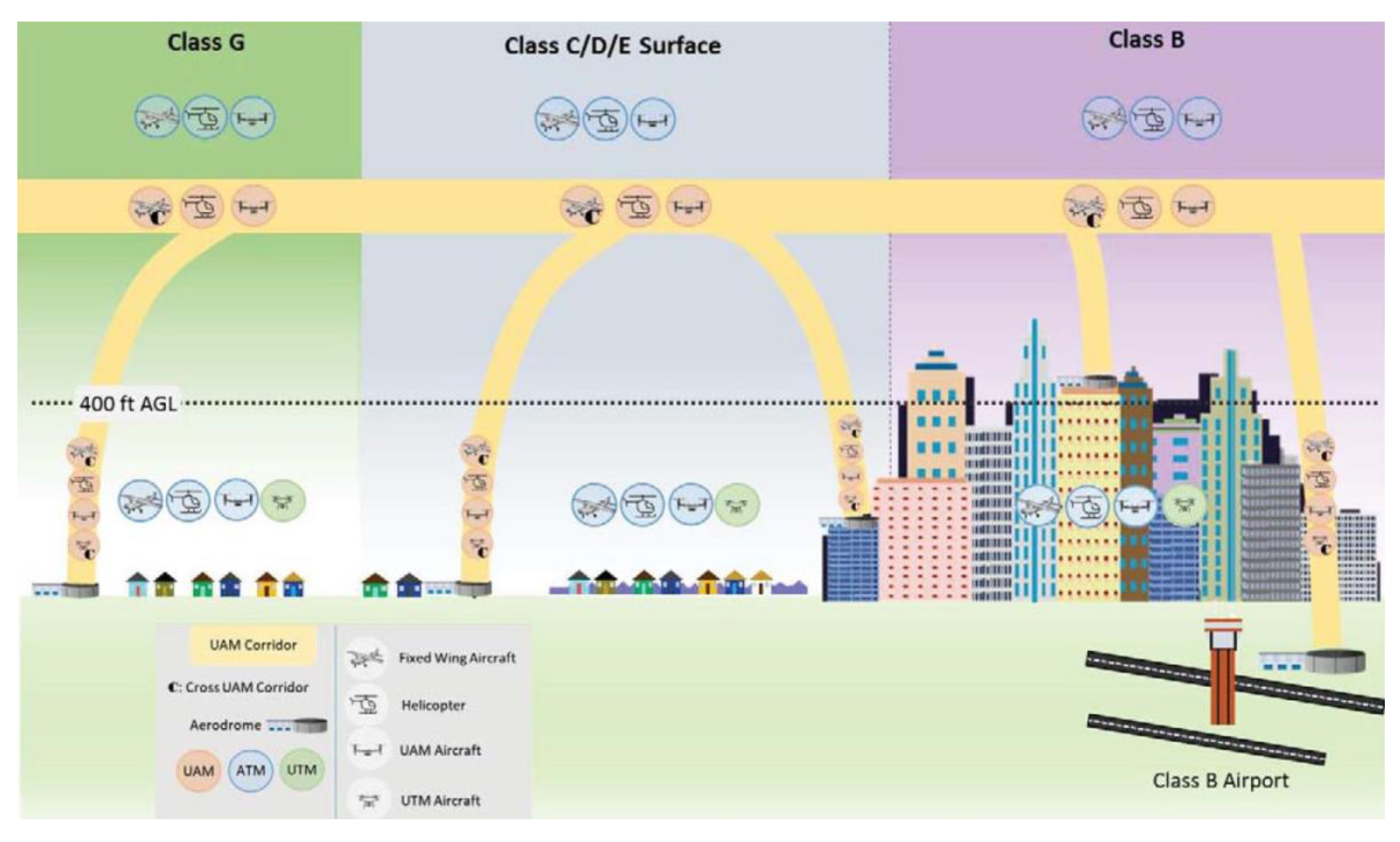
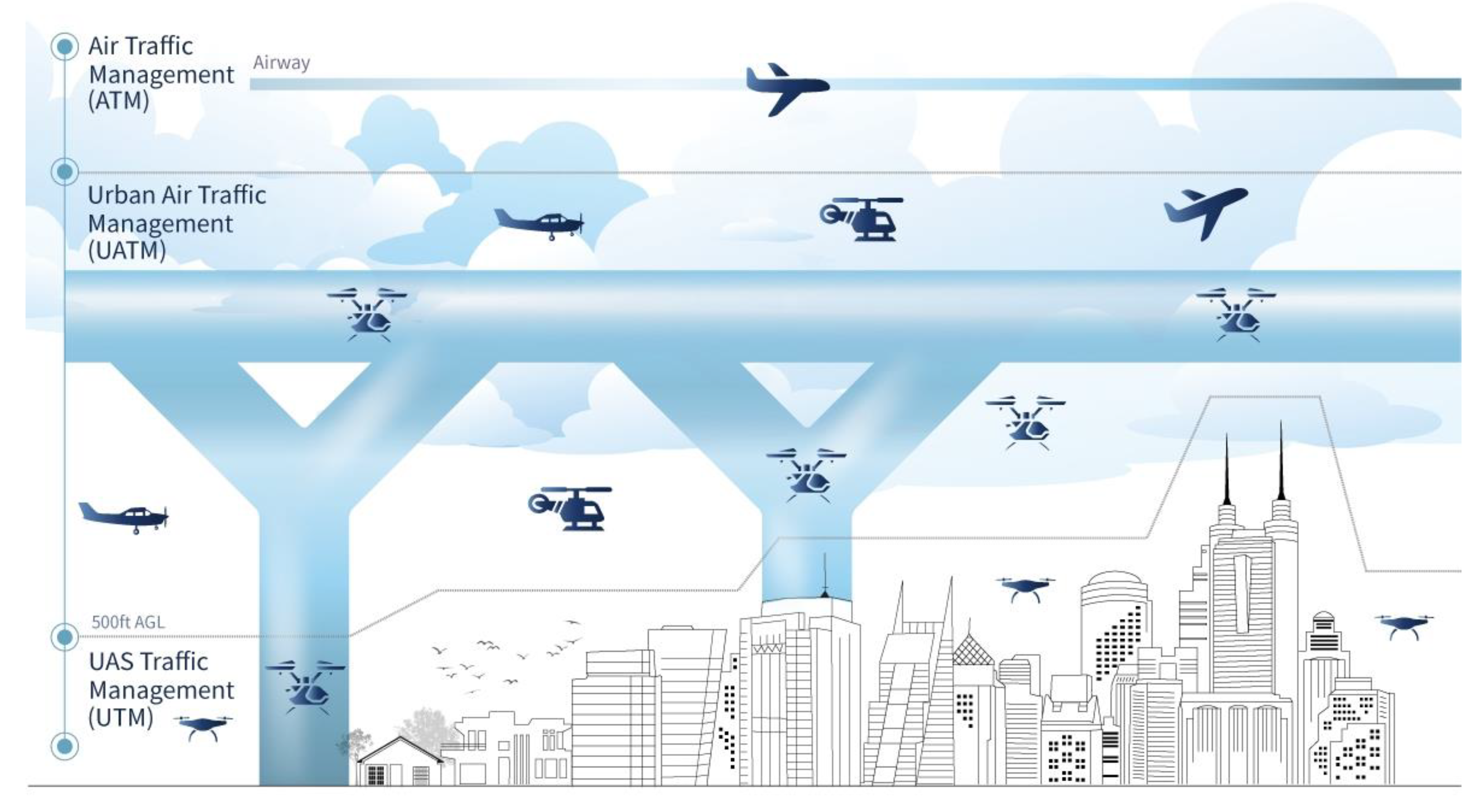
2.2. UAM Airspace Environment Analysis through Concept of Operations (ConOps)
2.3. Establishment of Assumptions for UAM Flight Operations
- Operations are carried out within the scope of established laws and policies.
- For safe operations, stakeholders also do their best to maintain safety and security.
- The UAM vehicle is designed and developed to be able to operate within certain airspaces and to satisfy required performances.
- It satisfies the communication navigation surveillance and information (CNSi) performances that are built for UAM operations by CNSi infrastructure agency.
- UAM can operate both controlled and uncontrolled zones within the range that allows strategic and tactical collision avoidance and separation. However, real-time information sharing should be available within ATM, UTM, and UATM.
- Various systems, infrastructure, and policies for UAM are flexibly applied according to the maturity level of development.
- During UAM operations, a situation must be considered in which all or part of the operating system (e.g., UATM systems, etc.) can suddenly shut down, so a backup system and an alternative system need to be installed.
- Holding areas are established in sections where the turning radius is permitted.
- UAM vehicles that satisfy the required performance can enter the holding area.
- When using the UAM corridor while cruising, autonomous flight is given priority, but the pilot can control the vehicle manually in the case of an abnormal situation.
- The UAM corridor size is based on CORUS’ RUNP-50m.
3. Holding Area Conceptual Design and Turning Performance Analysis
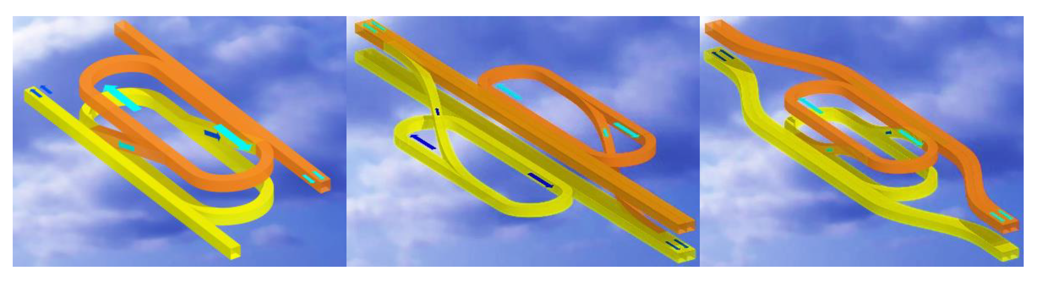
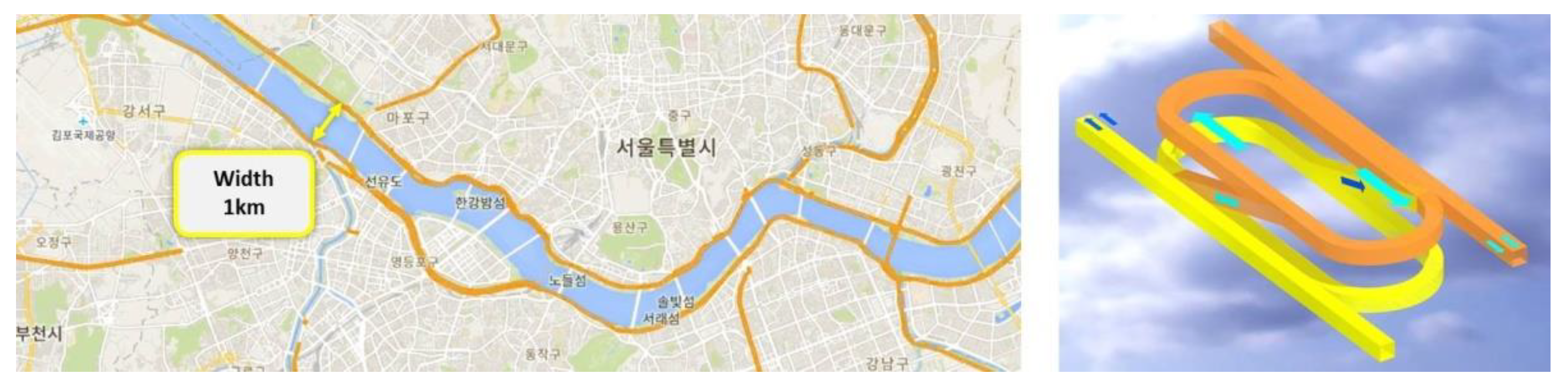
3.1. Holding Area Conceptual Design for Low-Altitude Environments
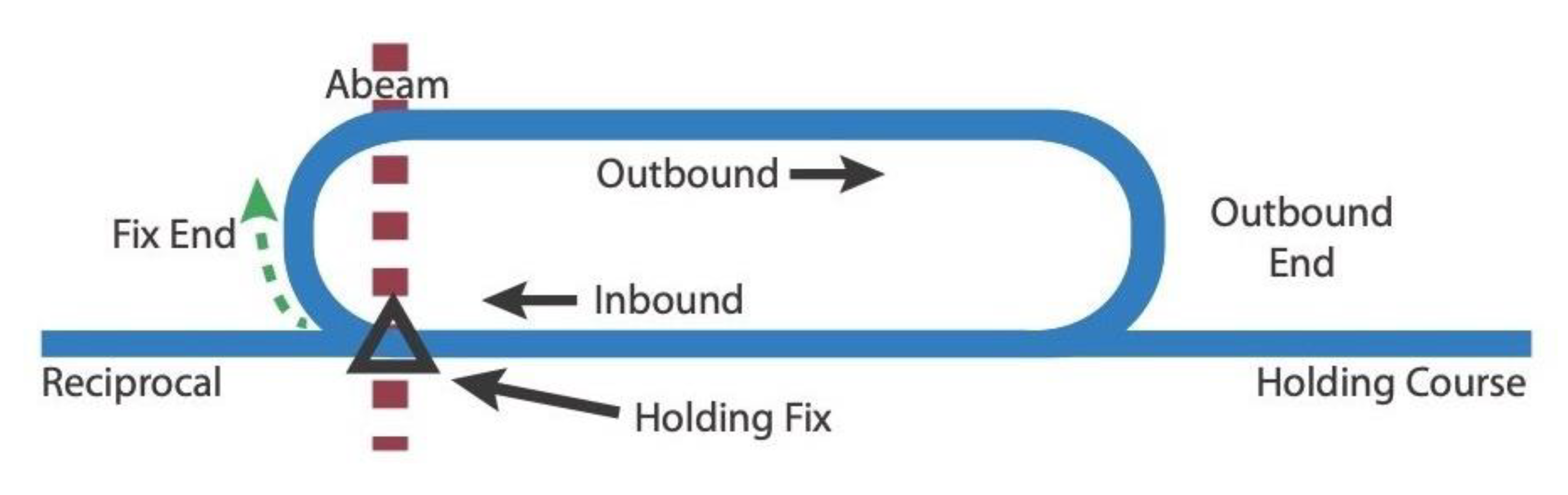
- The UAM holding area serves as a link between UAM flight routes in opposite directions.
- The difference in altitude of the UAM flight routes is 1000 ft.
- Each UAM flight route is 100 m wide. (Apply RUNP-50) [7].
- The turning standard of UAM vehicles is the same right turn as that of conventional aircraft.
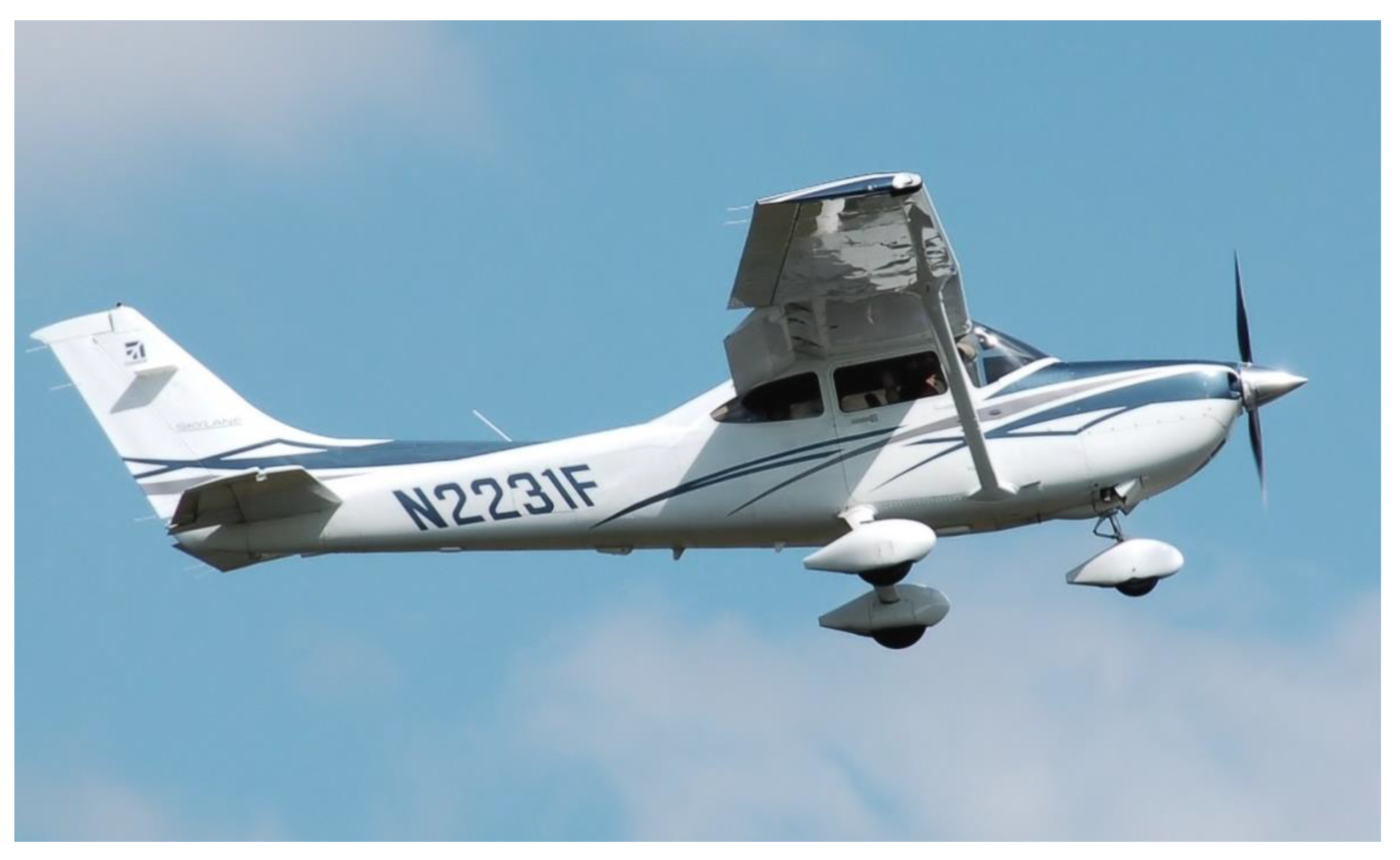
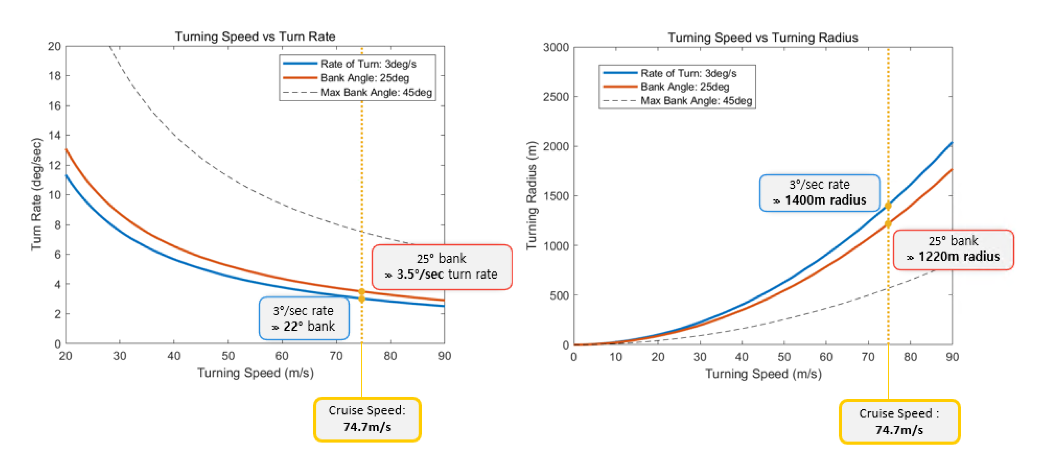
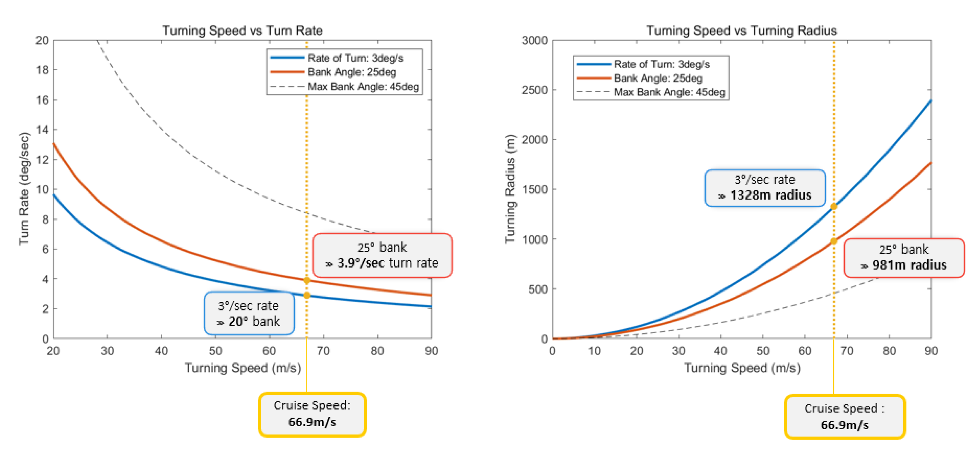
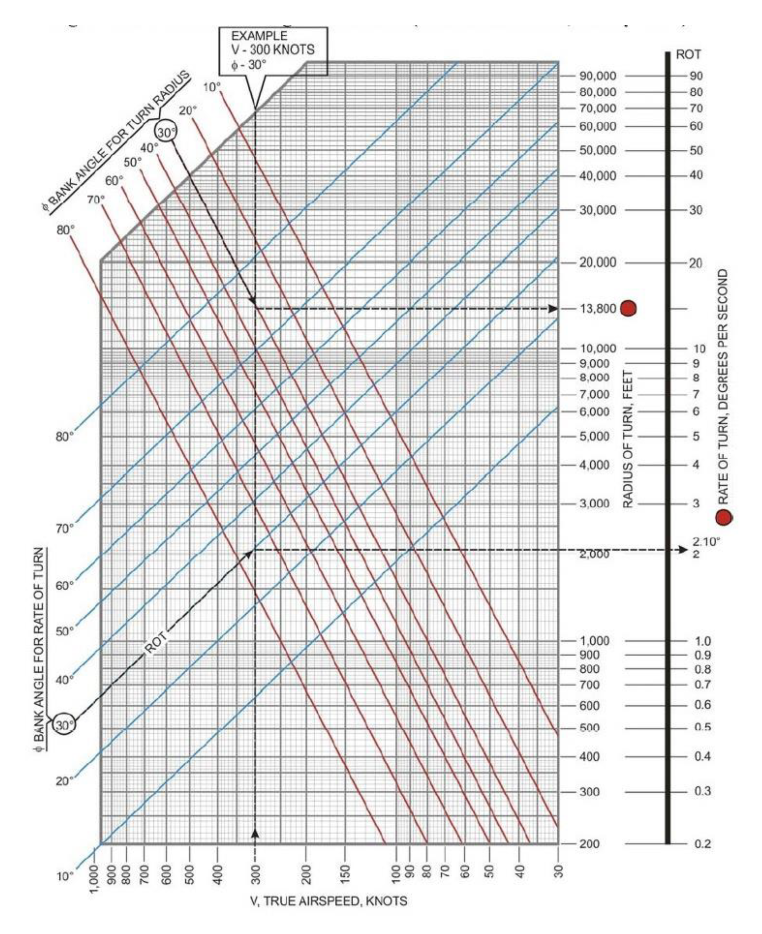
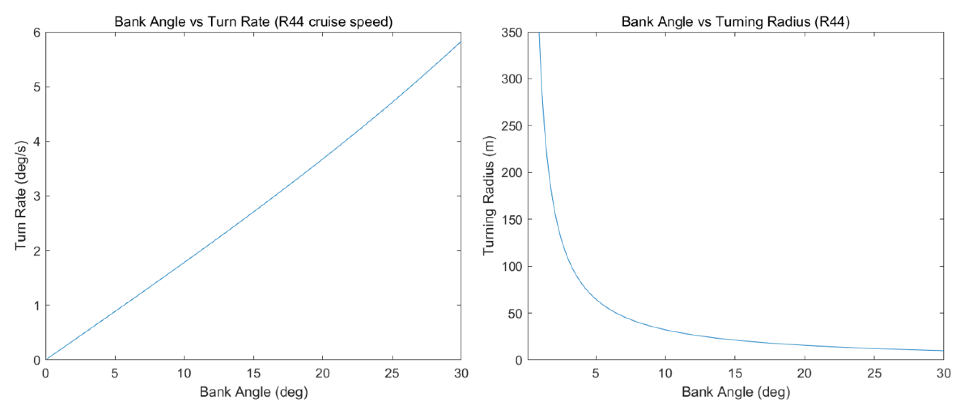
3.2. Current Aircraft Turning Performance Analysis
4. Case Study: Conceptual UAM Flight Routes and Establishment of Holding Areas
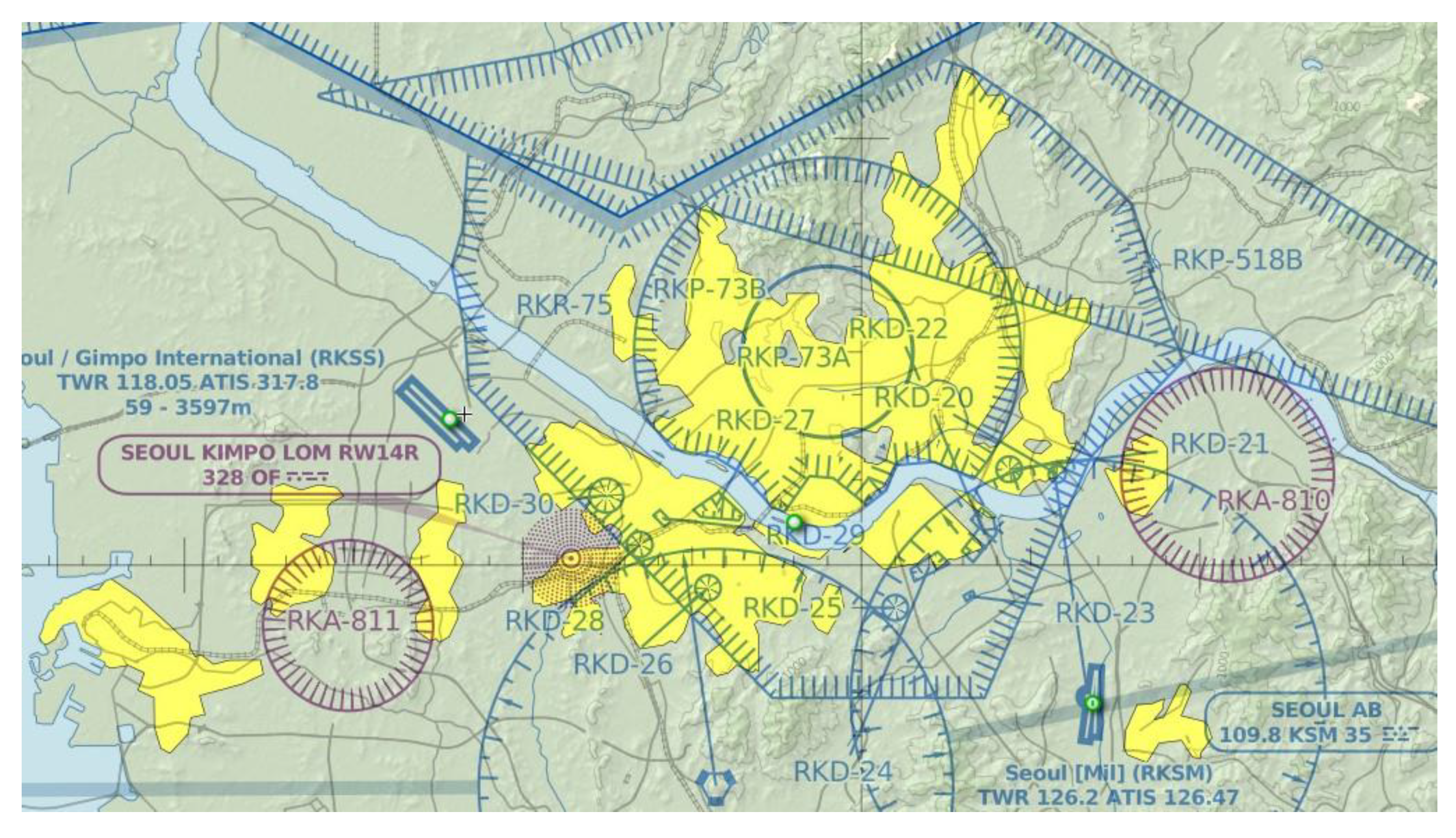
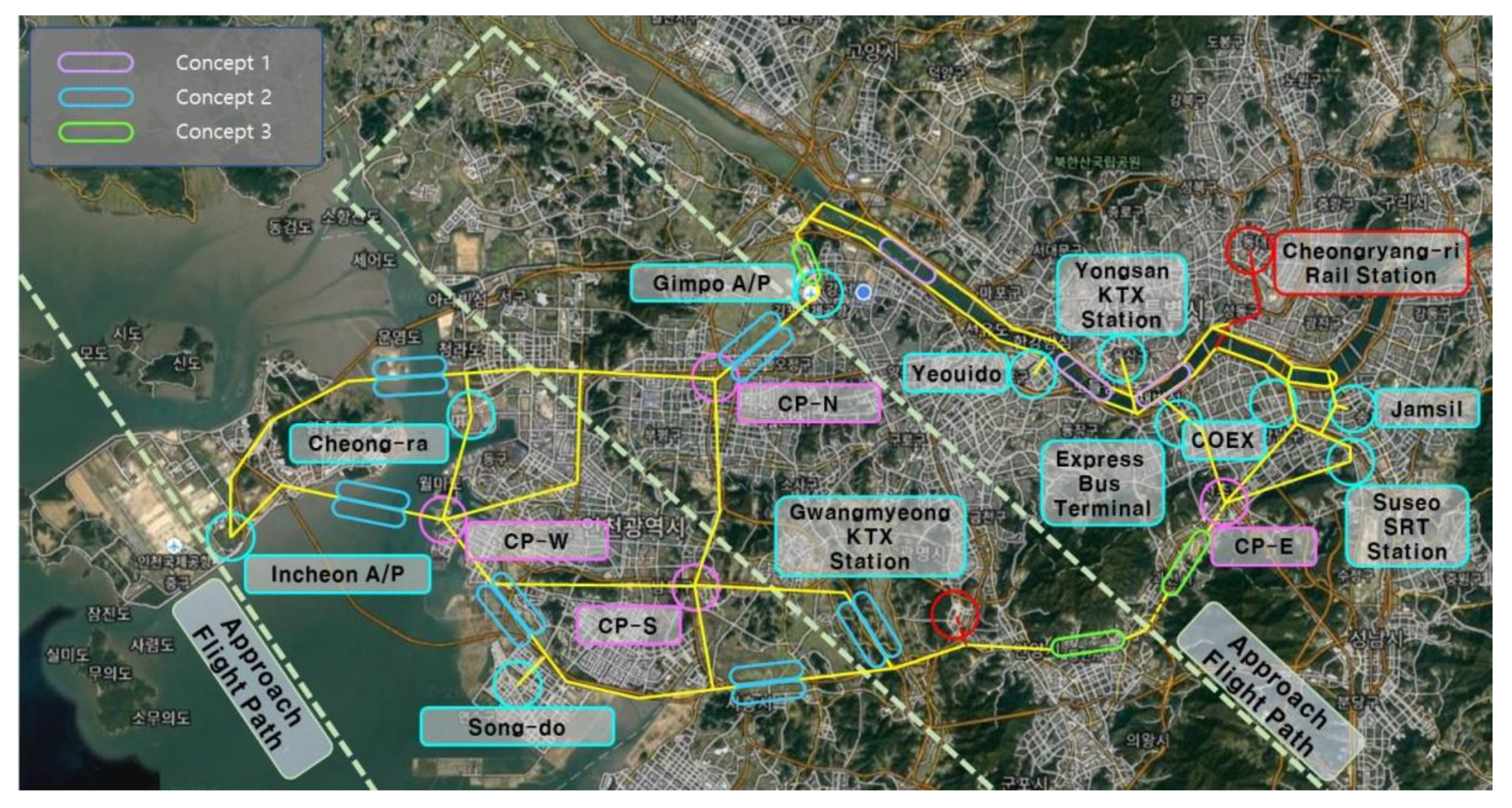
4.1. Analysis of Airspace Environment in Seoul–GyungIn Area
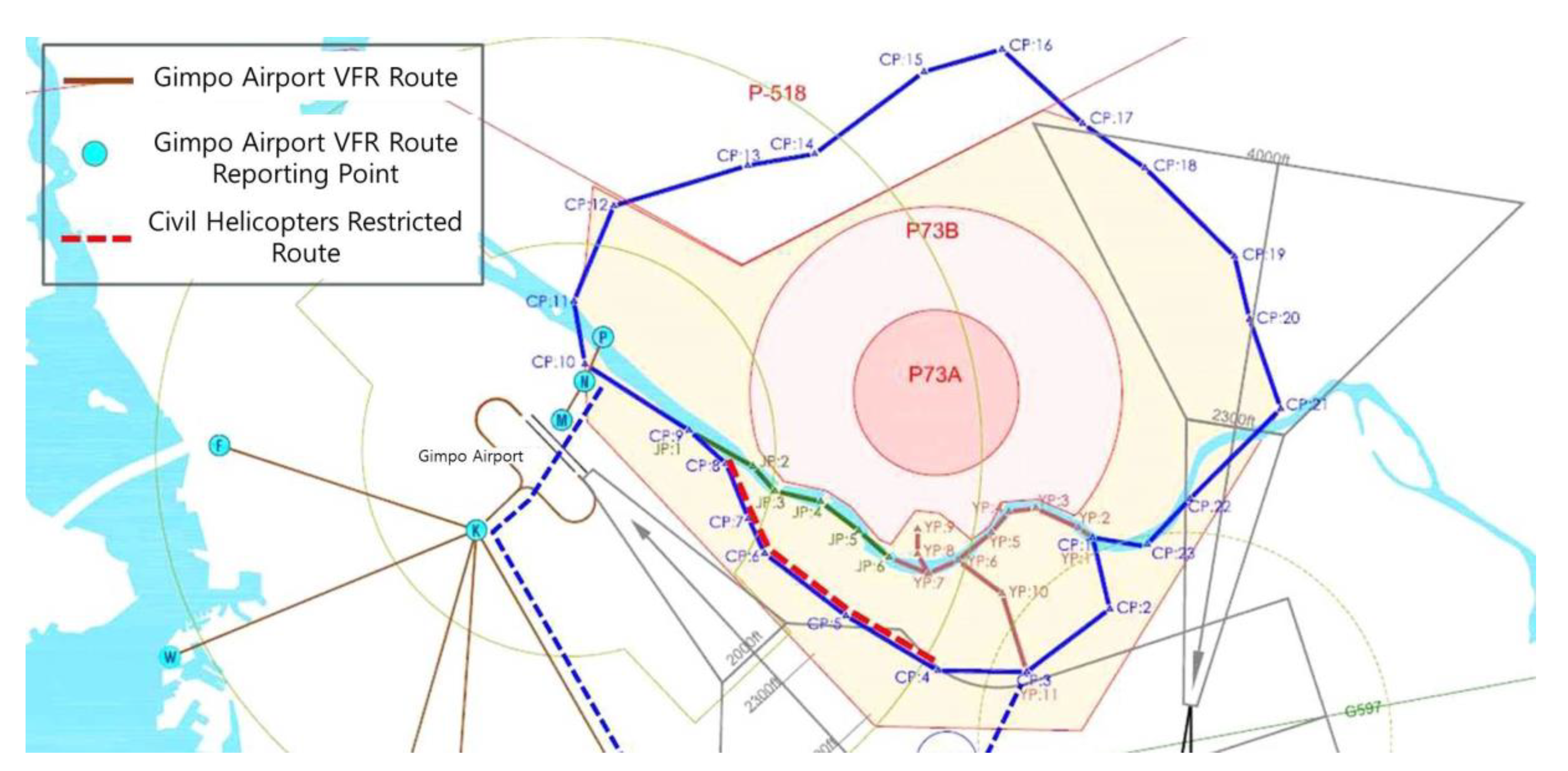
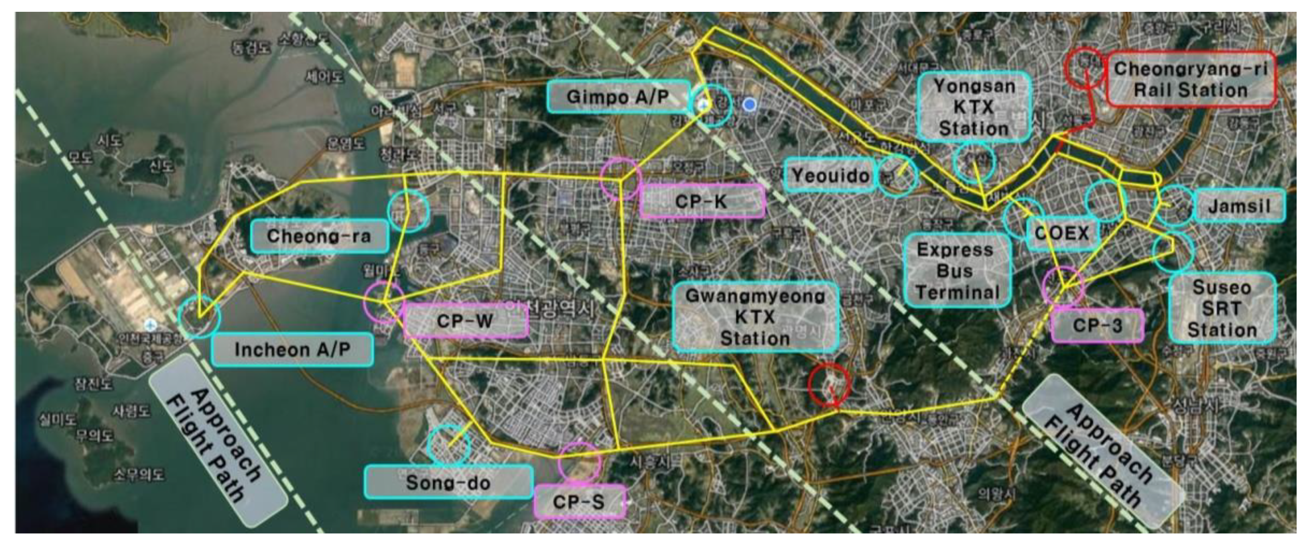
4.2. UAM Flight Routes Conceptual Design based on Seoul–GyungIn Area
4.3. Selecting Locations for Holding Area in Seoul–GyungIn Area
5. Case Study: UAM Vehicle’s Turning Performance Analysis and Validation
5.1. Selection of Holding Area Concept and UAM Vehicle for Turning Performance Analysis
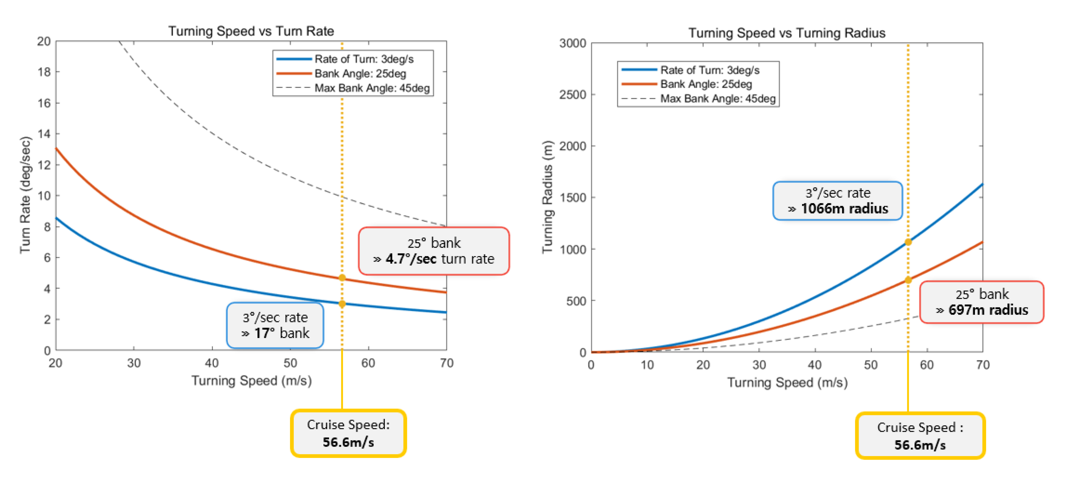
5.2. Turning Performance Analysis for Conceptual Holding Area Design Validation
5.3. Analysis Results
6. Conclusions
Author Contributions
Funding
Institutional Review Board Statement
Informed Consent Statement
Conflicts of Interest
References
- Lee, Y.J.; Kwag, T.H.; Jeong, G.M.; Ahn, J.H.; Chung, B.C.; Lee, J.W. Flight routes establishment through the operational concept analysis of Urban Air Mobility system. J. Korean Soc. Aeronaut. Space Sci. 2020, 48, 1021–1031. [Google Scholar] [CrossRef]
- Burnside, J. Hold Everything. Aviation Safety. Available online: https://www.aviationsafetymagazine.com/features/hold-everything/ (accessed on 14 September 2021).
- Baur, S.; Schickram, S.; Homulenko, A.; Martinez, N.; Dyskin, A. Roland Berger Focus—Urban Air Mobility; Roland Berger: Munich, Germany, 2018; pp. 13–14. [Google Scholar]
- Lee, J.W.; Gong, B.H. Urban Air Mobility (UAM) Concept of Operations v1.0—The Beginning of Next-Generation Urban Flight; Konkuk University and Korean Air: Seoul, Korea, 2021; pp. 7–15. [Google Scholar]
- Bradford, S. Concept of Operations v1.0—Urban Air Mobility (UAM); Federal Aviation Administration (FAA): Washington, DC, USA, 2020; pp. 4–5.
- Lee, J.S.; Lee, Y.J.; Kwag, T.H.; Kang, B.Y.; Min, J.S.; Lee, J.W. A study on the conceptual design of holding area for flight of Urban Air Mobility (UAM) and establishment of suitable places. In Proceedings of the 2021 KSAS Spring Conference, Samcheok, Korea, 2021; p. 7. [Google Scholar]
- European Union. U-space Concept of Operations. In CORUS Consortium; European Union: Brussels, Belgium, 2019; pp. 36–37. [Google Scholar]
- Section 3. En Route Procedures. Federal Aviation Administration (FAA). Available online: https://www.faa.gov/air_traffic/publications/atpubs/aim_html/chap5_section_3.html (accessed on 14 September 2021).
- Duncan, J.S. Airplane Flying Handbook; Federal Aviation Administration (FAA): Washington, DC, USA, 2016; p. 118.
- Cessna 182 Skylane. Wikipedia. Available online: https://en.wikipedia.org/wiki/Cessna_182_Skylane (accessed on 15 September 2021).
- Pingstone, A. File: Cessna182T Skylane N2231F Cotswold Airshow 2010 arp.jpg. Wikimedia Commons. Available online: https://commons.wikimedia.org/wiki/File:Cessna182t_skylane_n2231f_cotswoldairshow_2010_arp.jpg (accessed on 15 September 2021).
- Hoon, N.R. The Aviation Calculation. Blog: How to Fly. 24 August 2020. Available online: https://blog.daum.net/skyfalcon/47 (accessed on 28 September 2021).
- Thurber, M. Eco Helicopters Launching Urban Air Mobility Operations. AINonline. 25 September 2020. Available online: https://www.ainonline.com/aviation-news/general-aviation/2020-09-25/eco-helicopters-launching-urban-air-mobility-operations (accessed on 15 September 2021).
- R44 Raven II & Clipper II. Robinson Helicopter Company. Available online: https://robinsonheli.com/r44-specifications/ (accessed on 15 September 2021).
- Robinson R44. Wikipedia. 31 July 2021. Available online: https://en.wikipedia.org/wiki/Robinson_R44 (accessed on 15 September 2021).
- Kim, K.W. The Metropolitan Area’s Population Exceeds 50% of the Total Population of Korea for the First Time in History. Hani, 6 January 2020. Available online: https://www.hani.co.kr/arti/area/area_general/923381.html (accessed on 14 September 2021).
- SkyVector—Aeronautical Charts. SkyVector. Online. Available online: https://skyvector.com/ (accessed on 14 September 2021).
- AIP (Aeronautical Information Publication). ENR 1.2 Visual Flight Rules; Office of Civil Aviation: Seoul, Korea, 2018; p. 27.
- Joint Republic of Korean Government. K-UAM Roadmap; Joint Republic of Korean Government: Sejong, Korea, 2020; p. 21.
- Ahn, J.H.; Zin, W.T.; Lee, J.R.; Lee, Y.J.; Min, J.S.; Tyan, M.; Nah, S.H.; Lee, J.W. Performance operational analysis study on hydrogen fuel cell Urban Air Mobility. In Proceedings of the 2020 KSAS Fall Conference, Jeju, Korea, 18–20 November 2020; p. 7. [Google Scholar]
- OPPAV Development Group. OPPAV Configuration; OPPAV Development Group: Daejeon, Korea, 2020. [Google Scholar]
- KARI OPPAV. Electric VTOL News, Vertical Flight Society. Available online: https://evtol.news/kari-pav/ (accessed on 14 September 2021).


| Types | Features | Configurations | |
|---|---|---|---|
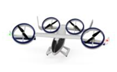
| Wingless Type | Multicopter Type |
|  |
| Winged Type | Lift‒Thrust Type |
| 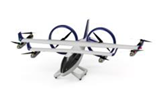 |
| Vectored Thrust Type |
|  | |
| Concepts | Features | Pros | Cons |
|---|---|---|---|
| Concept 1 | This holding area can be established in areas where the cruising flight route is set laterally and the turn width is limited. |
|
|
| Concept 2 | This holding area is established in areas that can secure a sufficiently large space. |
|
|
| Concept 3 | This holding area can be established in an area where space is limited but a holding area is essential. |
|
|
| Variables | Definition | Unit |
|---|---|---|
| Lift force | N | |
| Weight of aircraft | N | |
| m | Mass of aircraft | kg |
| Airspeed | m/s | |
| Bank angle | degree | |
| Load factor | - | |
| Turning radius | m | |
| Turn rate | degree/second |
| Item Classification | Specifications | |
|---|---|---|
| General characteristics | Length | 8.84 m |
| Wingspan | 10.97 m | |
| Height | 2.84 m | |
| Wing area | 16.2 m2 | |
| Empty weight | 894 kg | |
| Max. takeoff weight | 1406 kg | |
| Performance | Maximum speed | 280 km/h (150 knots) |
| Cruise speed | 269 km/h (145 knots) | |
| Stall speed | 91 km/h (49 knots) | |
| Never exceed speed | 324 km/h (175 knots) | |
| Range | 1720 km | |
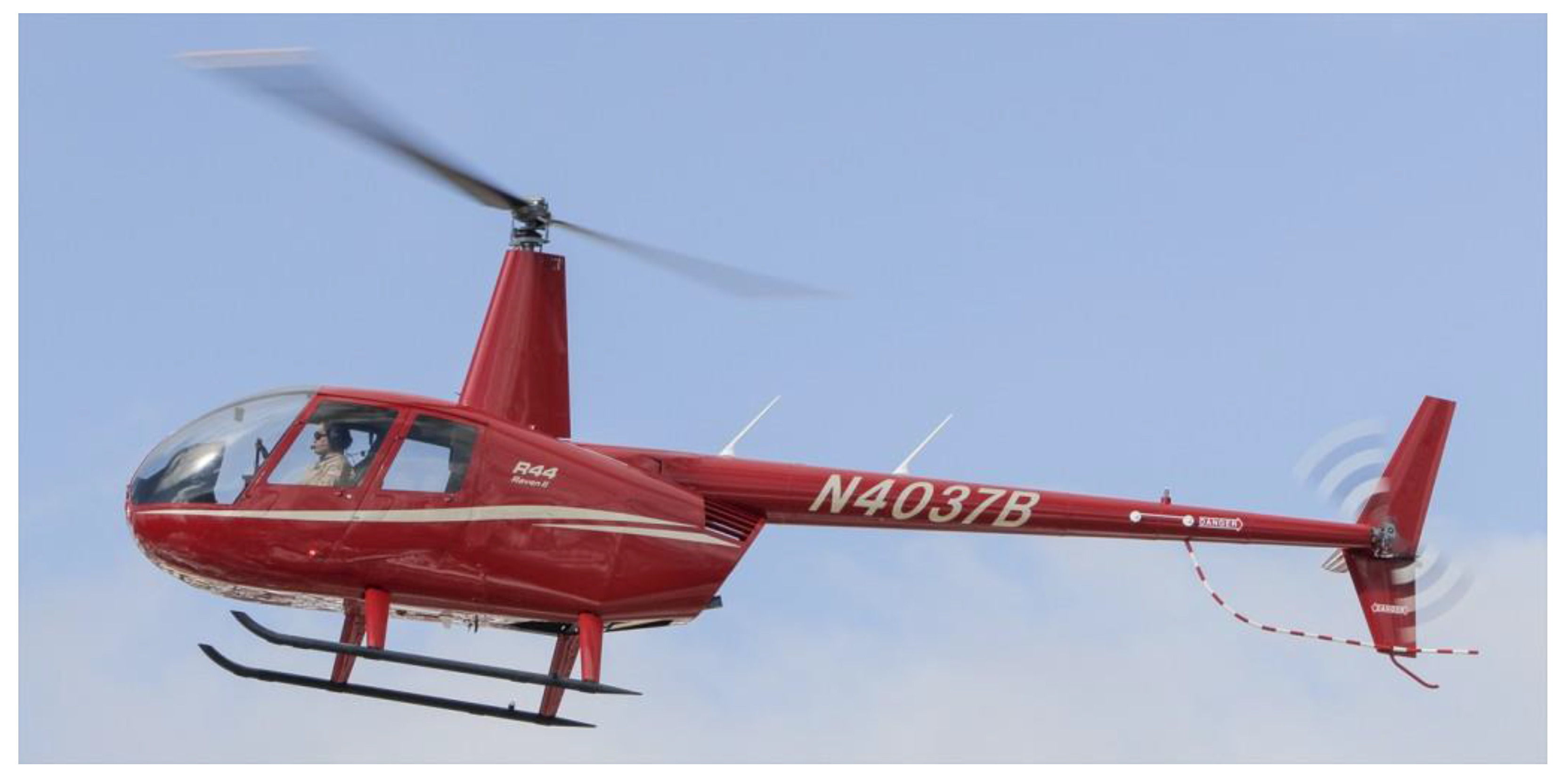
| Item Classification | Specifications | |
|---|---|---|
| General characteristics | Length | 11.66 m |
| Height | 3.28 m | |
| Empty weight | 683 kg | |
| Gross weight | 1134 kg | |
| Main rotor diameter | 33 ft (10 m) | |
| Performance | Maximum speed | 240 km/h (130 knots) |
| Cruise speed | 202 km/h (109 knots) | |
| Range | 560 km | |
| Altitude restrictions | 14,000 ft (4300 m) | |
| Specifications | KADA’s UAM Vehicle | KARI’s OPPAV |
|---|---|---|
| Length | 7 m | 9.2 m |
| Wingspan | 8.6 m | 10.5 m |
| Height | 2.99 m | 3.5 m |
| Wing area | 15.11 m2 | - |
| Empty weight | 1100 kg | 550 kg |
| Max. takeoff weight | 1559 kg | 650 kg |
| Maximum speed | 263 km/h (142 knots) | 240 km/h (130 knots) |
| Cruise speed | 203 km/h (110 knots) | 200 km/h (108 knots) |
| Stall speed | 96 km/h (52 knots) | 111 km/h (60 knots) |
| Range | 1025 km | 60 km |
Publisher’s Note: MDPI stays neutral with regard to jurisdictional claims in published maps and institutional affiliations. |
© 2021 by the authors. Licensee MDPI, Basel, Switzerland. This article is an open access article distributed under the terms and conditions of the Creative Commons Attribution (CC BY) license (https://creativecommons.org/licenses/by/4.0/).
Share and Cite
Lee, Y.; Lee, J.; Lee, J.-W. Holding Area Conceptual Design and Validation for Various Urban Air Mobility (UAM) Operations: A Case Study in Seoul–GyungIn Area. Appl. Sci. 2021, 11, 10707. https://doi.org/10.3390/app112210707
Lee Y, Lee J, Lee J-W. Holding Area Conceptual Design and Validation for Various Urban Air Mobility (UAM) Operations: A Case Study in Seoul–GyungIn Area. Applied Sciences. 2021; 11(22):10707. https://doi.org/10.3390/app112210707
Chicago/Turabian StyleLee, Youngjae, Junseok Lee, and Jae-Woo Lee. 2021. "Holding Area Conceptual Design and Validation for Various Urban Air Mobility (UAM) Operations: A Case Study in Seoul–GyungIn Area" Applied Sciences 11, no. 22: 10707. https://doi.org/10.3390/app112210707
APA StyleLee, Y., Lee, J., & Lee, J.-W. (2021). Holding Area Conceptual Design and Validation for Various Urban Air Mobility (UAM) Operations: A Case Study in Seoul–GyungIn Area. Applied Sciences, 11(22), 10707. https://doi.org/10.3390/app112210707