
Characterisation of Microstructure and Mechanical Properties of Linear Friction Welded α+β Titanium Alloy to Nitinol

 , , and
Abstract
:Featured Application
Abstract
1. Introduction
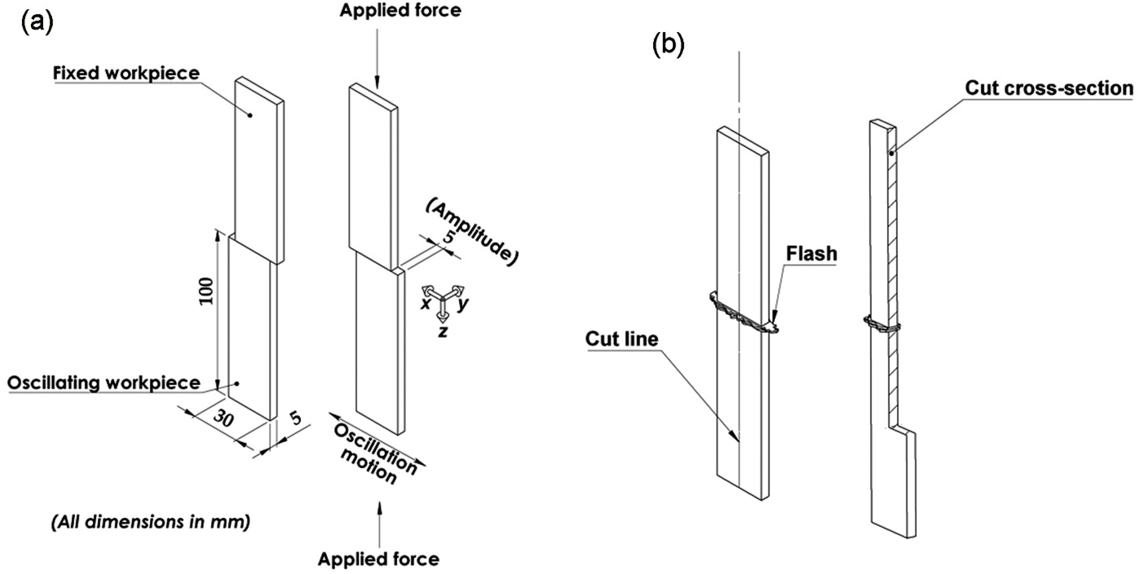
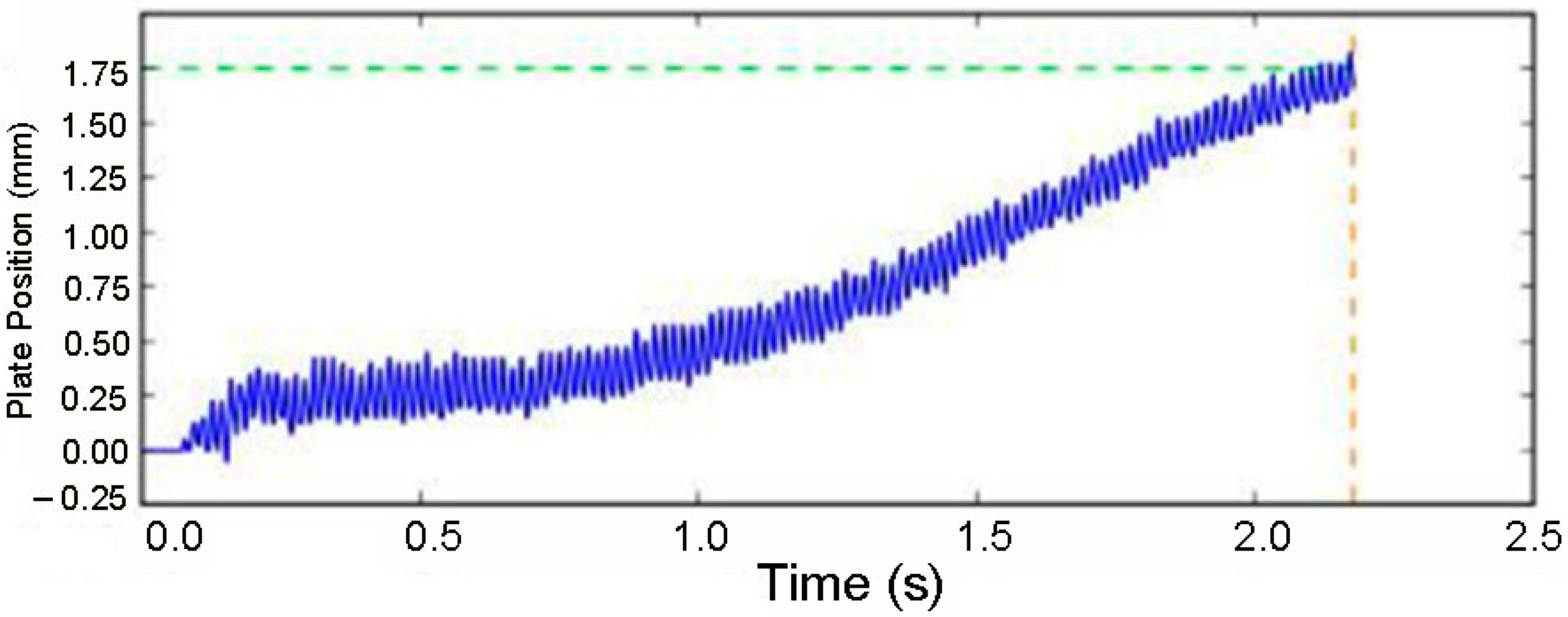
Schematic of Base Plates and Their Setup in the Linear Friction Welding Machine
2. Materials and Experiment
3. Results and Discussion
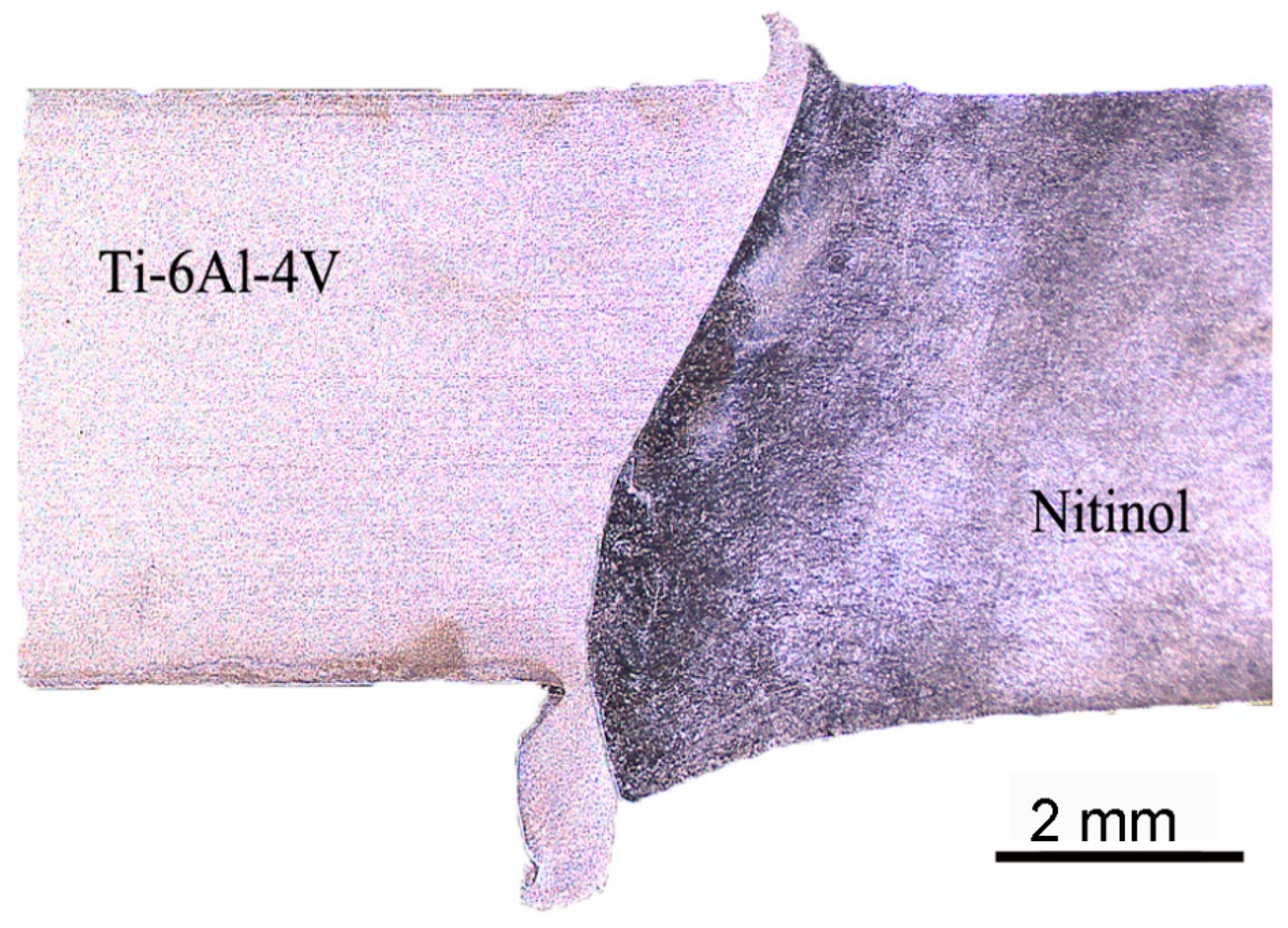
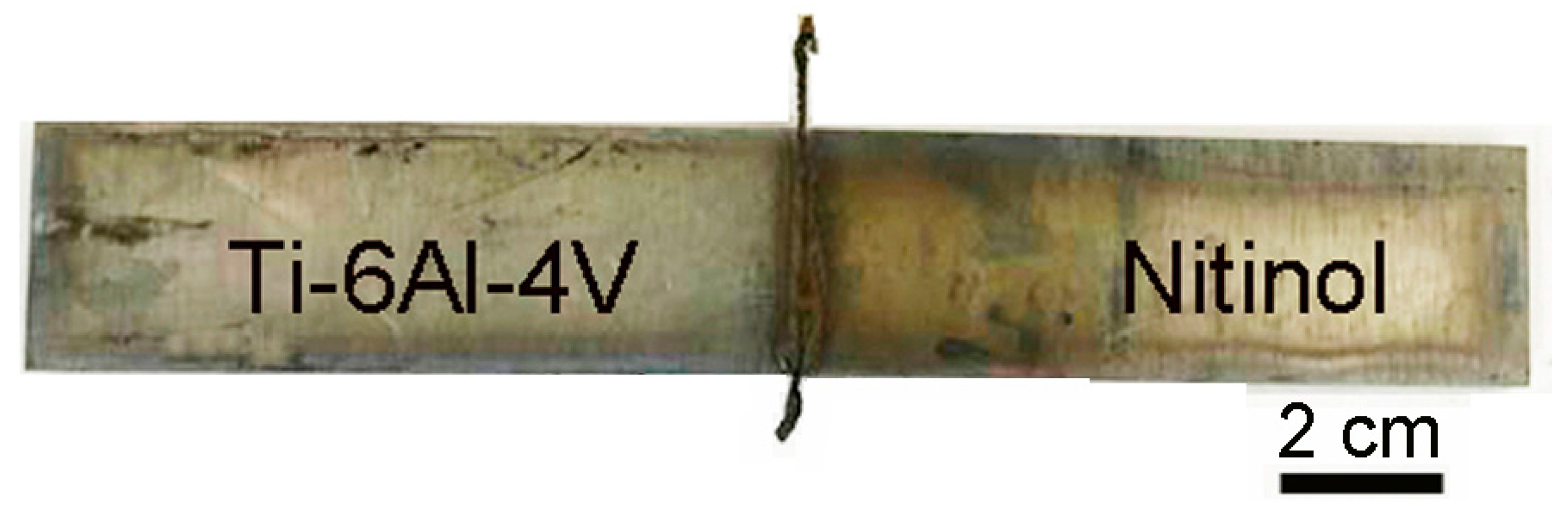
3.1. Macrostructure
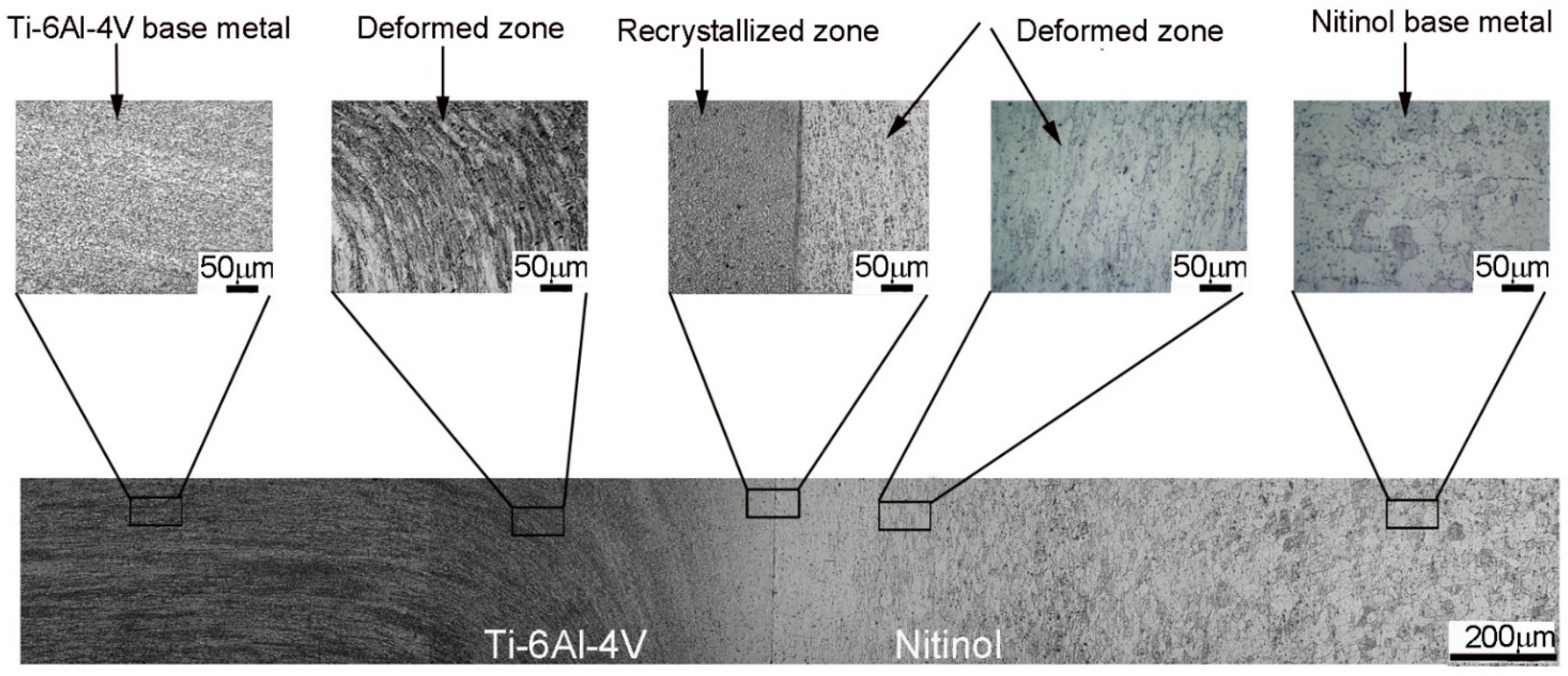
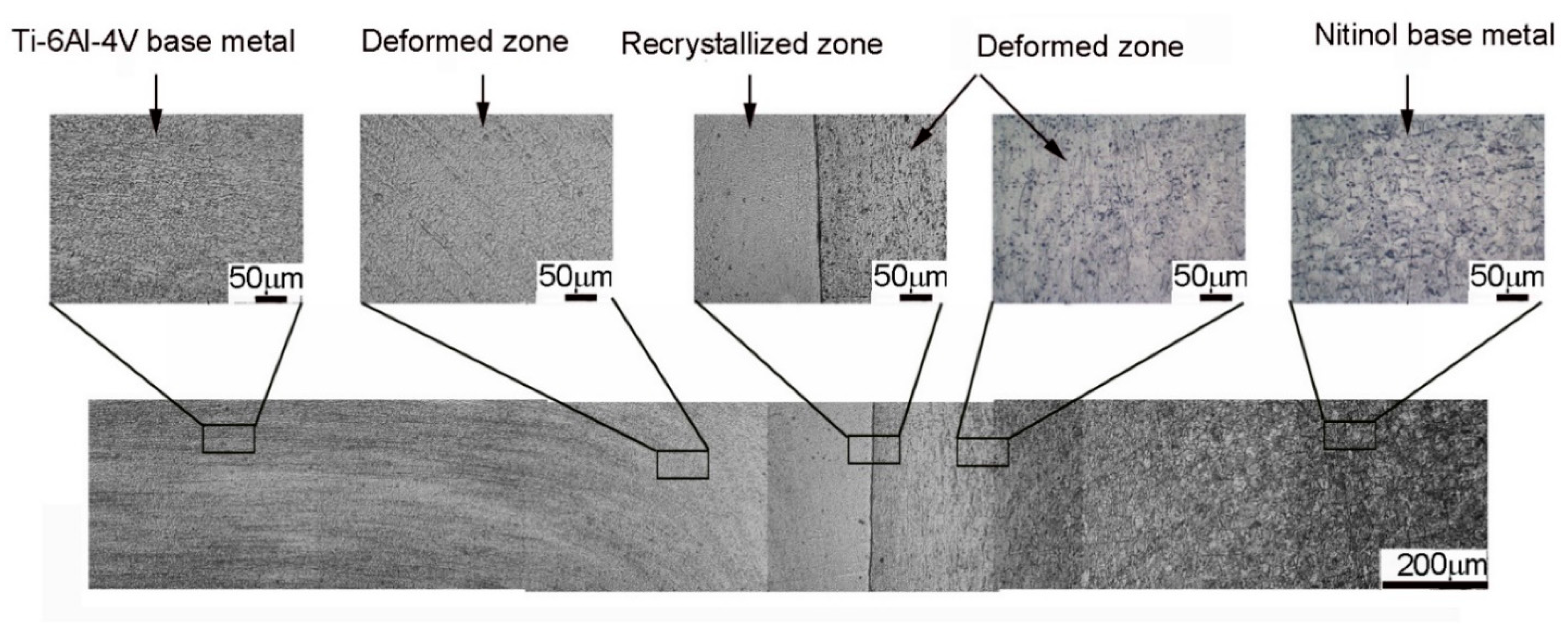
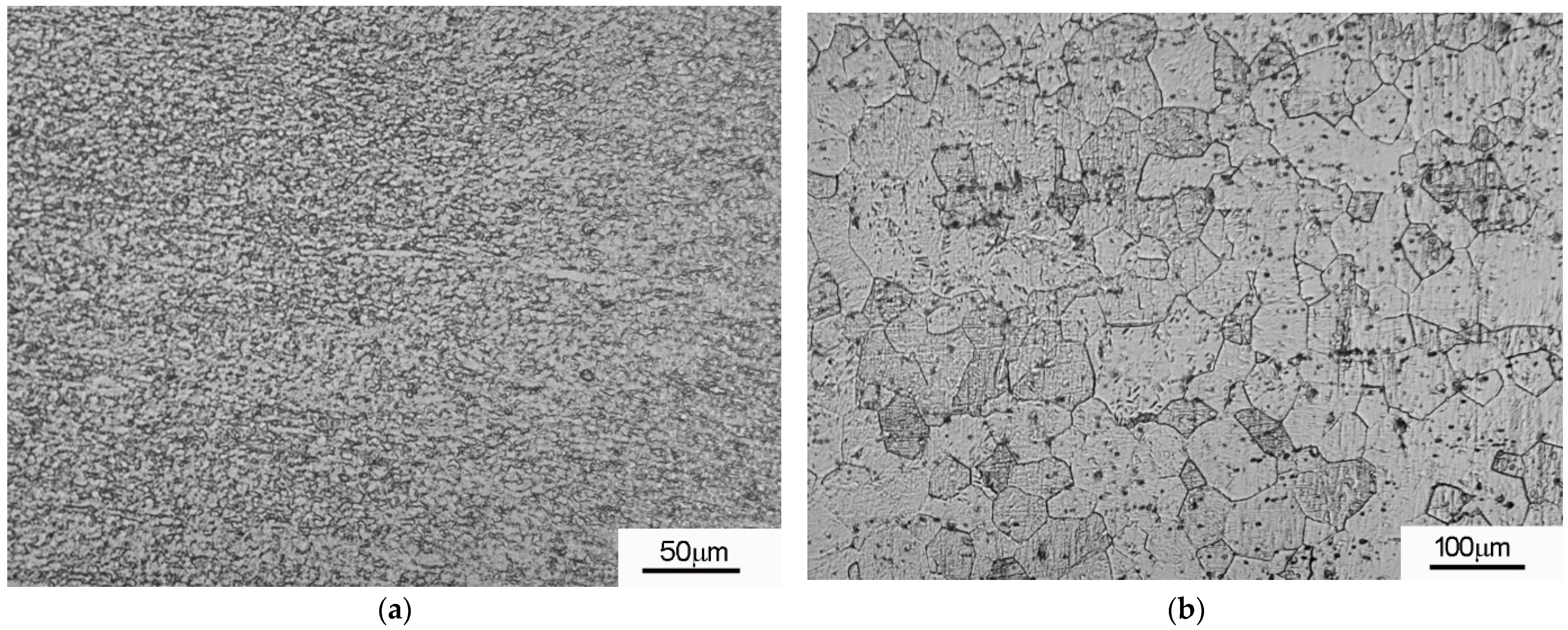
3.2. Microstructure
3.3. Mechanical Properties
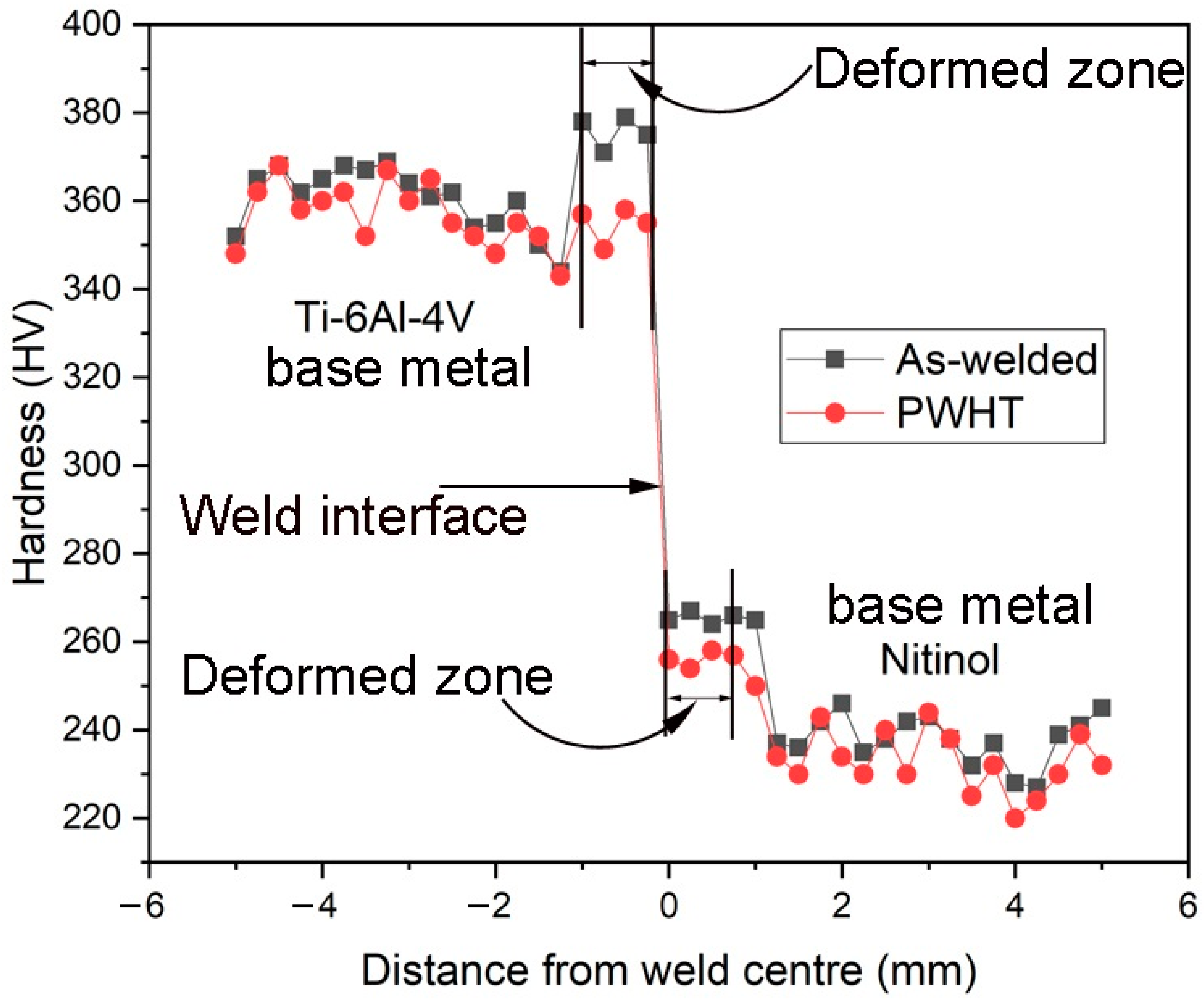
3.3.1. Hardness
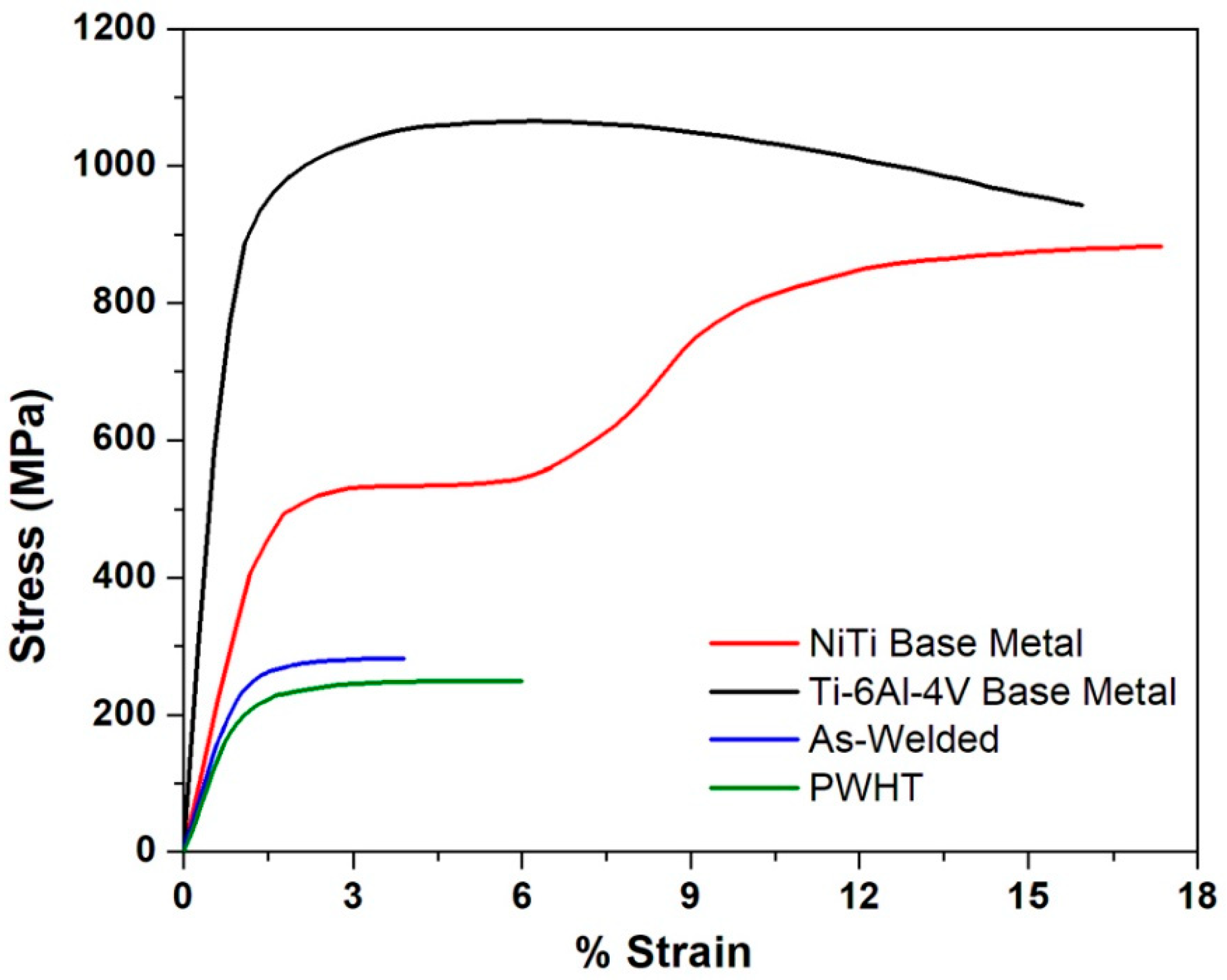
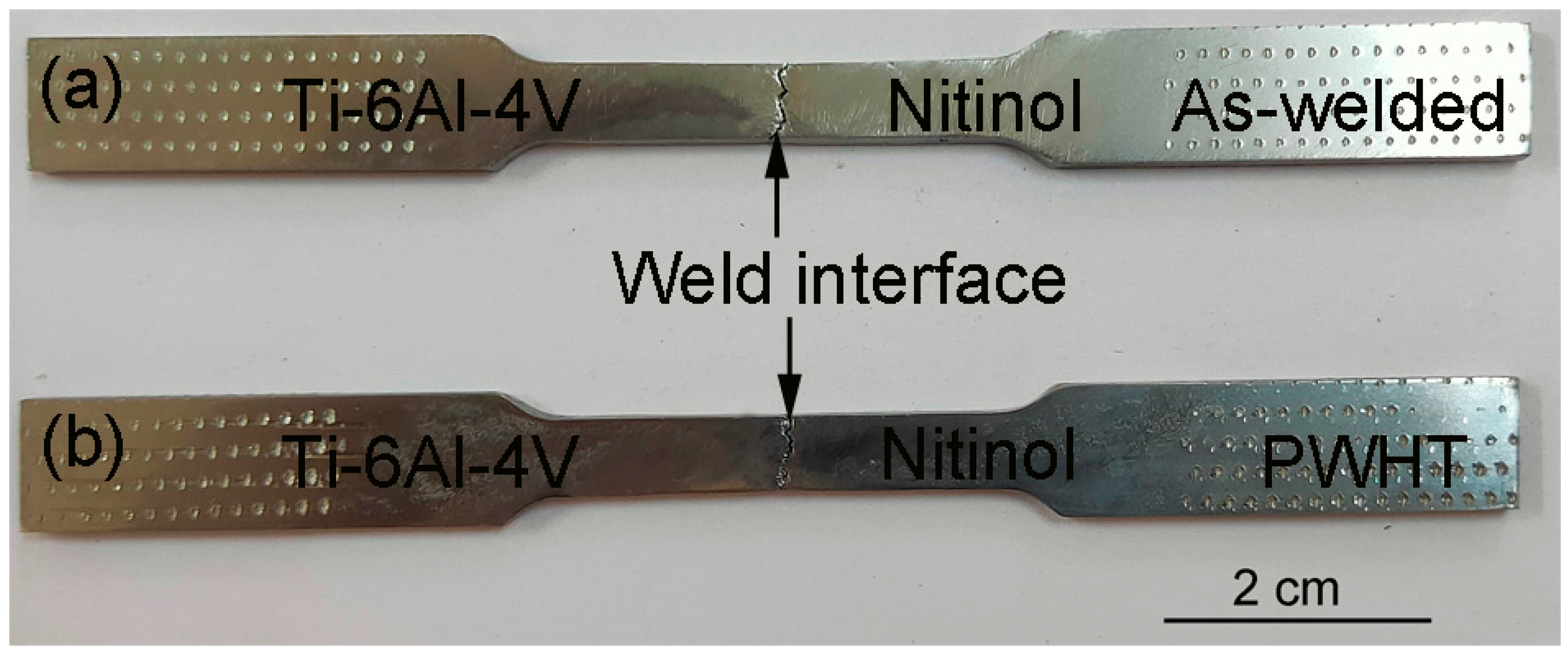
3.3.2. Tensile Properties
4. Conclusions
- A defect-free dissimilar Ti-6Al-4V/Nitinol weld (no cracks, solidification cracking, incomplete bonding) could be obtained by a linear friction welding technique.
- The macrostructure of dissimilar Ti-6Al-4V/Nitinol welds exhibited more flash on the Ti-6Al-4V side, and little flash on Nitinol side can be attributed to drop-in flow stresses of Ti-6Al-4V at high temperatures.
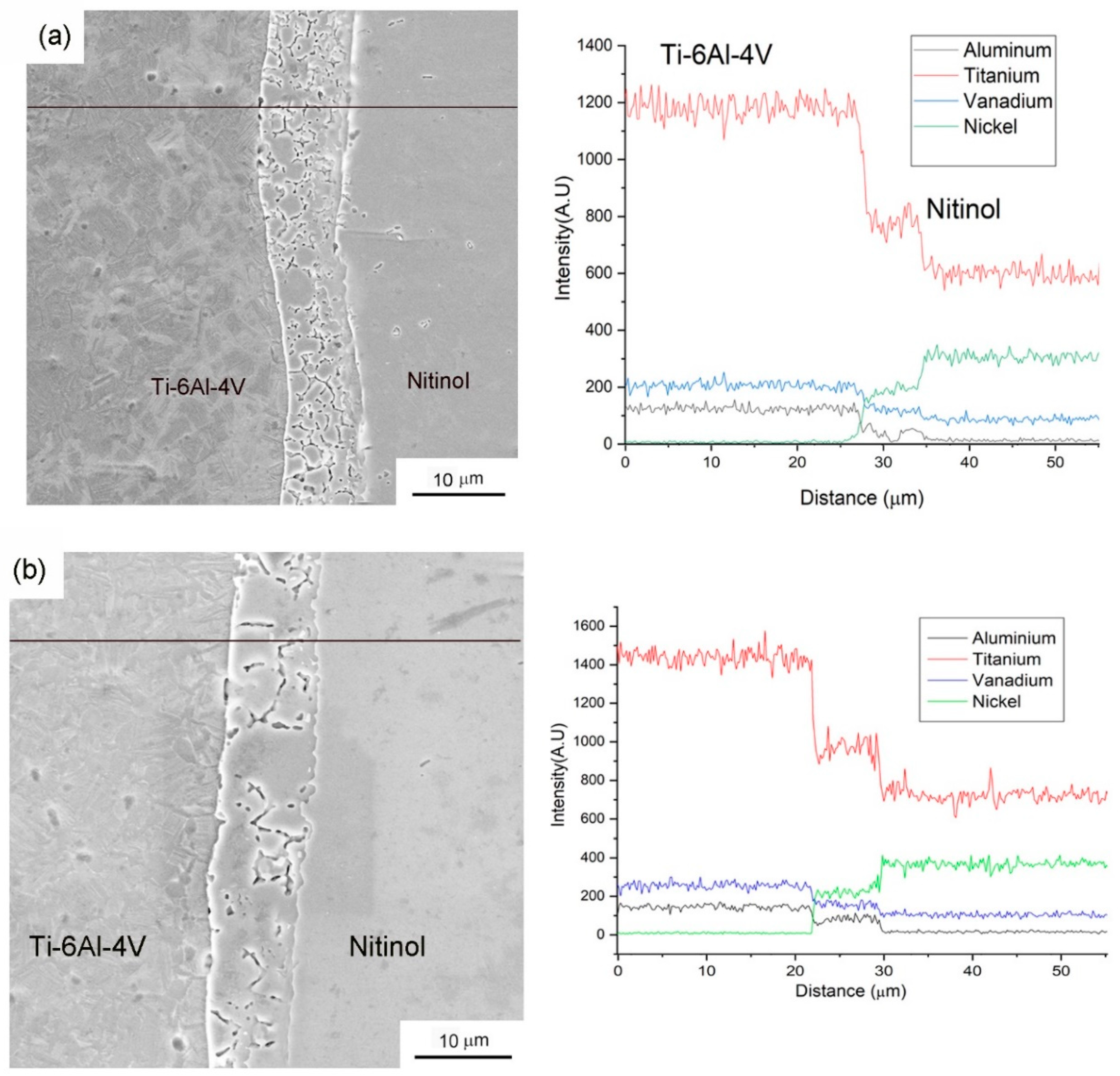
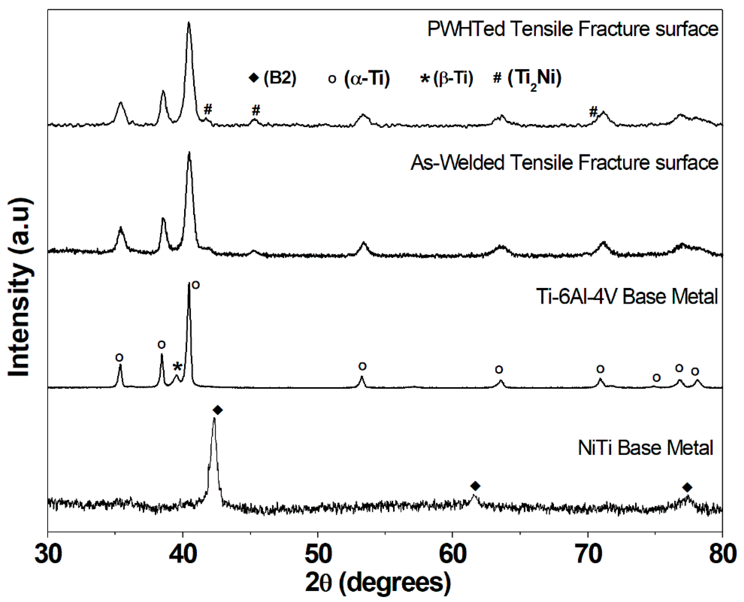
- X-ray diffraction studies revealed a formation of titanium-rich intermetallics (Ti2Ni) on the fracture surface of linear friction welds in the as-welded and PWHT conditions. This could be attributed to the diffusion of Ti being higher at the weld interface than Ni.
- The dissimilar Ti-6Al-4V/Nitinol linear friction welded joint exhibited a slightly higher ultimate tensile strength (UTS) and low ductility (UTS = 282 MPa, 3.9% elongation) compared with PWHT condition (UTS = 250 MPa, 5.9% elongation), and this may be attributed to high residual stresses in the as-welded condition and Ti2Ni brittle intermetallics present at the weld interface.
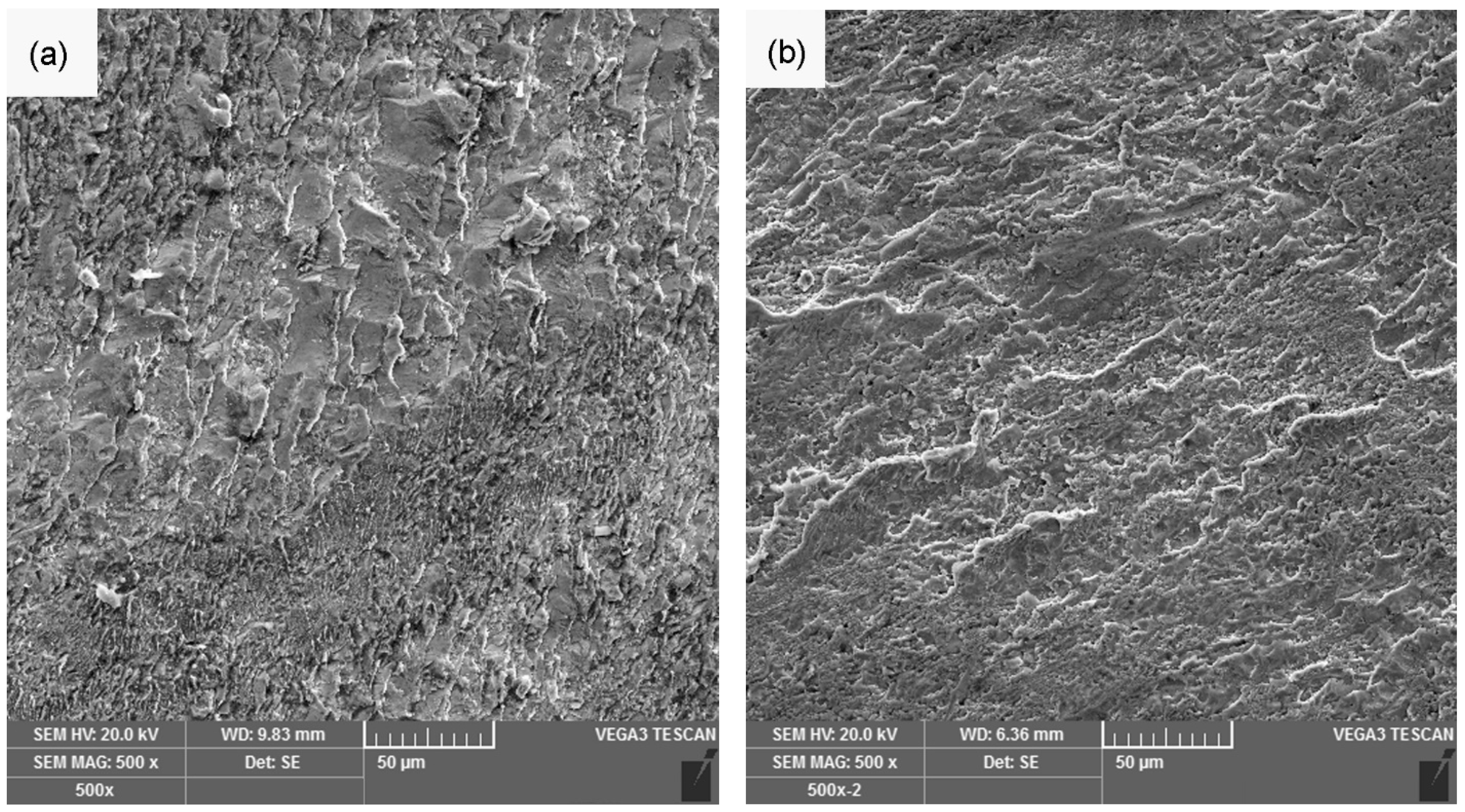
- The tensile fracture surfaces of the dissimilar Ti-6Al-4V/Nitinol linear friction welds exhibited cleavage (brittle) mode of fracture due to the formation of Ti2Ni intermetallics at the weld interface.
Author Contributions
Funding
Institutional Review Board Statement
Informed Consent Statement
Data Availability Statement
Acknowledgments
Conflicts of Interest
References
- Jani, J.M.; Leary, M.; Subic, A.; Gibson, M.A. A Review of Shape Memory Alloy Research, Applications and Opportunities. Mater. Des. 2014, 56, 1078–1113. [Google Scholar] [CrossRef]
- Saedi, S.; Turabi, A.S.; Andani, M.T.; Moghaddam, N.S.; Elahinia, M.; Karaca, H.E. Texture, aging, and superelasticity of selective laser melting fabricated Ni-rich NiTi alloys. Mater. Sci. Eng. A 2017, 686, 1–10. [Google Scholar] [CrossRef]
- Boyer, R.R. Titanium and titanium alloys. In Metals Handbook; Davis, J.R., Ed.; ASM International: Materials Park, OH, USA, 1998; pp. 575–588. ISBN 978-0-87170-654-6. [Google Scholar]
- Niinomi, M. Mechanical properties of biomedical titanium alloys. Mater. Sci. Eng. A 1998, 243, 231–236. [Google Scholar] [CrossRef]
- Gurrappa, I. Characterization of titanium alloy Ti-6Al-4V for chemical, marine and industrial applications. Mater. Charact. 2003, 51, 131–139. [Google Scholar] [CrossRef]
- Sidambe, A. Biocompatibility of Advanced Manufactured Titanium Implants—A Review. Materials 2014, 7, 8168–8188. [Google Scholar] [CrossRef] [PubMed] [Green Version]
- Gould, J.E.; Baselack, W.A., III; Williams, J.C. Some aspects of welding on the structure and properties of titanium alloys. In Advanced Processing Methods for Titanium; Hasson, D.F., Hamilton, C.H., Eds.; The Metallurgical Society of AIME: Warrendale, PA, USA, 1982; pp. 203–223. [Google Scholar]
- Babu, N.K.; Raman, S.G.S.; Murthy, C.V.S.; Reddy, G.M. Influence of beam oscillation patterns on the structure and mechanical properties of Ti–6Al–4V electron beam weldments. Sci. Technol. Weld. Join. 2005, 10, 583–590. [Google Scholar] [CrossRef]
- Dalgaard, E.; Wanjara, P.; Gholipour, J.; Cao, X.; Jonas, J.J. Linear friction welding of a near-b titanium alloy. Acta Mater. 2012, 60, 770–780. [Google Scholar] [CrossRef]
- Gupta, B.; Pandey, S.; Nahata, A.; Zhang, T.; Nahata, A. Bistable physical geometries for terahertz plasmonic structures using shape memory alloys. Adv. Opt. Mater. 2017, 5, 1601008. [Google Scholar] [CrossRef]
- Datta, S.; Raza, M.S.; Kumar, S.; Saha, P. Exploring the possibility of dissimilar welding of NiTi to Ti using Yb-fiber laser. Adv. Mater. Process. Technol. 2018, 4, 614–625. [Google Scholar] [CrossRef]
- Yuhua, C.; Yuqing, M.; Weiwei, L.; Peng, H. Investigation of welding crack in micro laser welded NiTiNb shape memory alloy and Ti6Al4V alloy dissimilar metals joint. Opt. Laser Technol. 2017, 91, 197–202. [Google Scholar] [CrossRef]
- Oliveira, J.P.; Panton, B.; Zeng, Z.; Andrei, C.M.; Zhou, Y.; Miranda, R.M.; Braz Fernandes, F.M. Laser joining of NiTi to Ti6Al4V using a Niobium interlayer. Acta Mater. 2016, 105, 9–15. [Google Scholar] [CrossRef]
- Zeng, Z.; Oliveira, J.P.; Yang, M.; Song, D.; Peng, B. Functional fatigue behavior of NiTi-Cu dissimilar laser welds. Mater. Des. 2017, 114, 282–287. [Google Scholar] [CrossRef]
- Senkevich, K.S.; Knyazev, M.I.; Runova, Y.E.; Shlyapin, S.D. Special Features of Formation of a TiNi—VT6 Diffusion Joint. Met. Sci. Heat Treat. 2013, 55, 419–422. [Google Scholar] [CrossRef]
- Rehman, A.U.; Babu, N.K.; Talari, M.K.; Usmani, Y.S.; Al-Khalefah, H. Microstructure and mechanical properties of dissimilar friction welding Ti-6Al-4V alloy to Nitinol. Metals 2021, 11, 109. [Google Scholar] [CrossRef]
- Zhou, X.; Chen, Y.; Huang, Y.; Mao, Y.; Yu, Y. Effects of niobium addition on the microstructure and mechanical properties of laser-welded joints of NiTiNb and Ti6Al4V alloy. J. Alloys Compd. 2018, 735, 2616–2624. [Google Scholar] [CrossRef]
- Zhan, Z.; Chen, Y.; Wang, S.; Huang, Y.; Mao, Y. Prevention of crack formation in electron-beam welded joints of dissimilar metal compounds (TiNi/Ti-6Al-4V). Met. Sci. Heat Treat. 2019, 61, 373–378. [Google Scholar] [CrossRef]
- Homma, T.; Takano, H.; Ozaki, T. Nanostructural analysis of welded Ti–6Al–4V by linear friction welding applied for blisk assemblies. Materialia 2019, 5, 100174. [Google Scholar] [CrossRef]
- Vairis, A.; Frost, M. High frequency linear friction welding of a titanium alloy. Wear 1998, 217, 117–131. [Google Scholar] [CrossRef]
- Chan, C.W.; Man, H.C.; Yue, T.M. Effect of postweld heat treatment on the microstructure and cyclic deformation behavior of laser-welded NiTi-shape memory wires. Metall. Mater. Trans. A 2012, 43, 1956–1965. [Google Scholar] [CrossRef]
- Yan, X.J.; Yang, D.Z.; Liu, X.P. Influence of heat treatment on the fatigue life of a laser-welded NiTi alloy wire. Mater. Characterisation 2007, 58, 262–266. [Google Scholar] [CrossRef]
- Geng, P.; Qin, G.; Ma, H.; Zhou, J.; Zhang, C.; Ma, N. Numerical modelling on the plastic flow and interfacial self-cleaning in linear friction welding of superalloys. J. Mater. Process. Technol. 2021, 296, 117198. [Google Scholar] [CrossRef]
- Muralimohan, C.H.; Muthupandi, V.; Sivaprasad, K. Properties of Friction Welding Titanium-stainless Steel Joints with a Nickel Interlayer. Procedia Mater. Sci. 2014, 5, 1120–1129. [Google Scholar] [CrossRef] [Green Version]
- Mishra, R.S.; Ma, Z.Y. Friction stir welding and processing. Mater. Sci. Eng. R Rep. 2005, 50, 1–78. [Google Scholar] [CrossRef]
- Senkevich, K.S.; Shlyapin, S.D. Investigation of the process of diffusion bonding of alloys based on titanium nickelide. Weld. Int. 2012, 26, 736–738. [Google Scholar] [CrossRef]
- Gotawala, N.; Shrivastava, A. Investigation of interface microstructure and mechanical properties of rotatory friction welded dissimilar aluminum-steel joints. Mater. Sci. Eng. A 2021, 825, 141900. [Google Scholar] [CrossRef]
- Kumar, A.S.; Khadeer, S.A.; Rajinikanth, V.; Pahari, S.; Kumar, B.R. Evaluation of bond interface characteristics of rotary friction welded carbon steel to low alloy steel pipe joints. Mater. Sci. Eng. A 2021, 824, 141844. [Google Scholar] [CrossRef]
- Ji, S.; Wang, Y.; Liu, J.; Meng, X.; Tao, J.; Zhang, T. Effects of welding parameters on material flow behavior during linear friction welding of Ti6Al4V titanium alloy by numerical investigation. Int. J. Adv. Manuf. Technol. 2016, 82, 927–938. [Google Scholar] [CrossRef]
- Miranda, R.M.; Assunção, E.; Silva, R.J.C.; Oliveira, J.P.; Quintino, L. Fiber laser welding of NiTi to Ti-6Al-4V. Int. J. Adv. Manuf. Technol. 2015, 81, 1533–1538. [Google Scholar] [CrossRef]
- Zoeram, A.S.; Mousavi, S.A. Laser welding of Ti–6Al–4V to Nitinol. Mater. Des. 2014, 61, 185–190. [Google Scholar] [CrossRef]
- Deng, Y.; Sheng, G.; Xu, C. Evaluation of the microstructure and mechanical properties of diffusion bonded joints of titanium to stainless steel with a pure silver interlayer. Mater. Des. 2013, 46, 84–87. [Google Scholar] [CrossRef]


| Elements | Ni | Co | Cr | Fe | C | N | O | H | Ti |
| Ti-6Al-4V | 6.01 | 4.0 | 0.13 | 0.03 | 0.01 | 0.003 | 0.112 | 0.007 | balance |
| Elements | Ni | Co | Cr | Fe | C | Nb | O | H | Ti |
| Nitinol | 55.6 | 0.005 | 0.003 | 0.012 | 0.03 | 0.005 | 0.032 | <0.001 | balance |
| Parameter | Final Chosen |
|---|---|
| Friction Pressure (MPa) | 190 |
| Forge Pressure (MPa) | 110 |
| Amplitude (mm) | 5 |
| Frequency (Hz) | 60 |
| Burn-off length (mm) | 3 mm |
| Forge time (s) | 2 s |
Publisher’s Note: MDPI stays neutral with regard to jurisdictional claims in published maps and institutional affiliations. |
© 2021 by the authors. Licensee MDPI, Basel, Switzerland. This article is an open access article distributed under the terms and conditions of the Creative Commons Attribution (CC BY) license (https://creativecommons.org/licenses/by/4.0/).
Share and Cite
Rehman, A.U.; Kishore Babu, N.; Talari, M.K.; Usmani, Y.; Alkhalefah, H. Characterisation of Microstructure and Mechanical Properties of Linear Friction Welded α+β Titanium Alloy to Nitinol. Appl. Sci. 2021, 11, 10680. https://doi.org/10.3390/app112210680
Rehman AU, Kishore Babu N, Talari MK, Usmani Y, Alkhalefah H. Characterisation of Microstructure and Mechanical Properties of Linear Friction Welded α+β Titanium Alloy to Nitinol. Applied Sciences. 2021; 11(22):10680. https://doi.org/10.3390/app112210680
Chicago/Turabian StyleRehman, Ateekh Ur, Nagumothu Kishore Babu, Mahesh Kumar Talari, Yusuf Usmani, and Hisham Alkhalefah. 2021. "Characterisation of Microstructure and Mechanical Properties of Linear Friction Welded α+β Titanium Alloy to Nitinol" Applied Sciences 11, no. 22: 10680. https://doi.org/10.3390/app112210680
APA StyleRehman, A. U., Kishore Babu, N., Talari, M. K., Usmani, Y., & Alkhalefah, H. (2021). Characterisation of Microstructure and Mechanical Properties of Linear Friction Welded α+β Titanium Alloy to Nitinol. Applied Sciences, 11(22), 10680. https://doi.org/10.3390/app112210680