Abstract
Complex and unknown areas in deep space exploration present major challenges to the motion ability of current space robots. Different from the traditional single-mode motion space robot, a compound motion robot with flexible movement and strong obstacle surmounting ability is proposed. Through the highly integrated structure design, the lightweight robot has the ability of rolling and jumping, and the kinematic characteristics of the robot under two motion modes are analyzed. This work provides a reference for the design of deep space exploration equipment with high motion capability in the future.
1. Introduction
For deep space exploration, the primary task of the detector is to reach the target area. However, the complex topography requires the space robot to have flexible movement mode and obstacle crossing ability. For flat terrain, rolling robots have the characteristics of fast-moving speed and wide range of motion [1]. Compared with wheeled, tracked, or legged structures [2,3,4], they have smaller volume and higher fault tolerance. When facing rough terrain or large obstacles, jumping robots are obviously the most reasonable choice, which can surmount an obstacle of their own size, or even several times their own size [5].
In order to realize the rolling or jumping function of robot, several methods have been developed. In the field of rolling robots, Ranjan M proposes a mass driven robot “sprerobot”, which can realize rolling forward by changing the mass distribution [6,7]. Nader A. Mansour proposed a modular closed-chain rolling robot with flexible shape memory alloy actuators, which can simulate the behavior of rolling animals [8]. For a jumping motion, NASA designed a jumping robot to meet the requirements of interstellar exploration across rugged terrain. The robot is mainly driven by a motor and stored in a compression spring, which can adjust the direction, takeoff, and landing [9,10,11]. Yoshimitsu T designed a kind of jumping robot “Minerva”, the robot uses the motor to rotate the torsion device inside the robot, and the reaction force on the ground makes it jump [12]. M. Kovač designed a torsion spring legged jumping robot, which has strong continuous jumping ability [13]. However, a single mode of movement creates difficultly in dealing with the complex and changeable deep space environment. If two or more motion modes are integrated to make up for the limitations of each motion mode, the motion ability of the robot will be greatly improved. Relevant studies have gradually been reported, Zhang has developed a wheeled jumping robot, which is driven by two wheels, when encountering obstacles, the internal spring legs can release energy to realize jumping [14], and Zhang of Chongqing University developed a crawling and rolling integrated robot composed of six crawling legs and multi-link auxiliary legs. Through the shape change of six legs of the robot, the robot has two motion modes of crawling and rolling [15].
In this paper, a rolling and jumping robot is designed and analyzed, both two modules of the motion mode are integrated into the robot structure which are controlled by wireless remote control. The rolling and turning movements of the robot are realized by changing the internal eccentric moment, and the spring energy storage device hidden in the sphere is used to provide the jumping power.
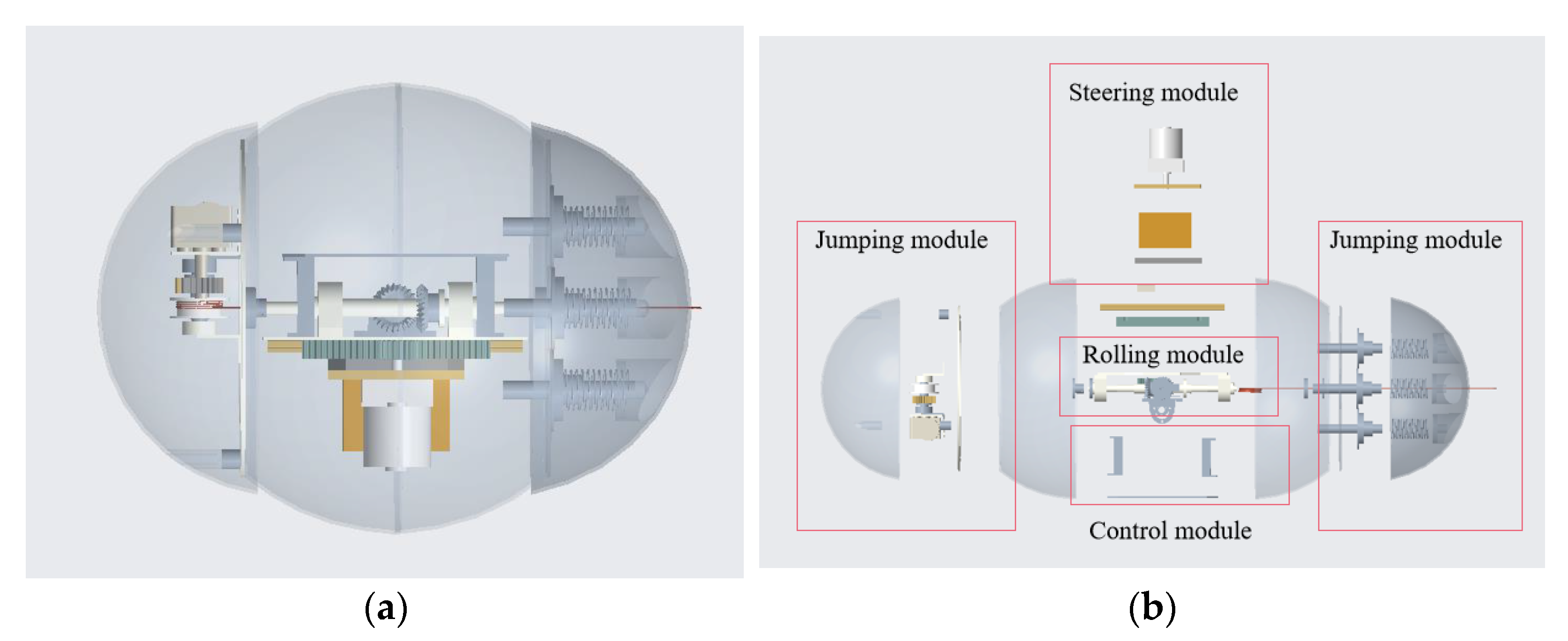
2. The Overall Design Scheme of the Rolling and Jumping Robot
In order to make the internal structure of the robot simpler and more compact, a single pendulum structure was adopted for the rolling mode, and the relevant mechanism of the steering module was taken as the counterweight to realize the centroid offset of the robot, so that no additional counterweight was needed to assemble, which effectively reduced the weight of the robot. On this basis, the jumping drive module and the energy storage and release module were placed on each side of the robot body, respectively, which maintained the static balance of the robot and avoided the mutual interference between multiple modules.
The structure diagram and exploded view of the robot is shown in Figure 1a,b. The robot was composed of a rolling module, steering module, jumping module, and control module.
Figure 1.
(a) The structure diagram of the rolling and jumping robot; (b) The exploded view of the rolling and jumping robot.
2.1. Rolling Module
The design of the rolling module referred to the model of single pendulum structure, including counterweight (1), sheet metal (2), major shaft (3), bearing (4), drive motor (5), and bevel gear set (6), shown in Figure 2a. The drive motor (5), which was connected with the major shaft (3) through a bevel gear set (6), transmitted energy to the counterweight and housing through the bearing (5).
Figure 2.
(a) The structure chart of the rolling module, 1-counterweight, 2-sheet metal, 3-major shaft, 4-bearing, 5-motor, and 6-bevel gear set; (b) Front view and top view of the jumping driver part.
By driving the motor to change the deflection angle of the counterweight in the motion plane, the forward or backward rolling motion was realized. The simplified model is shown in Figure 3a, and the schematic diagram of the counterweight position in rolling motion is shown in Figure 3b. Point A is the center of rotation of the pendulum and point B is the center of gravity of the simple pendulum.
Figure 3.
(a) The simplified model of the single pendulum-driven rolling robot; (b) The schematic diagram of the counterweight position in rolling motion.
2.2. Steering Module
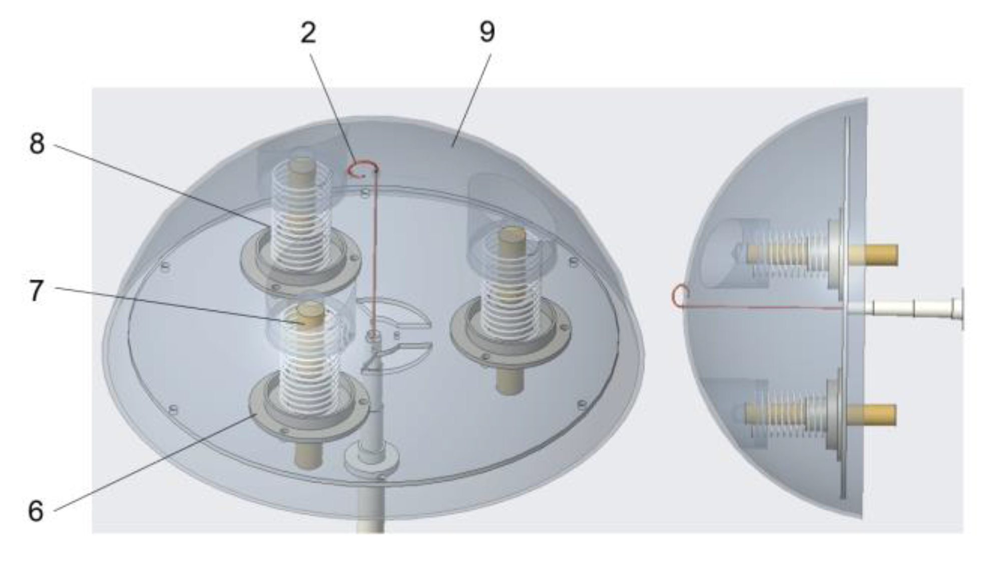
The structure of the steering module is shown in Figure 4, we used the steering motor (1), steering sheet metal 1 (2), steering sheet metal 2 (3), and the battery pack (8) as counterweights to reduce structural redundancy. The counterweight was connected to the major shaft through slide guide rails (6), slider (7), and gear-rack drive (4), shown in Figure 4.
Figure 4.
Structure diagram of the steering module. 1-steering motor, 2-steering sheet metal 1, 3-steering sheet metal 2, 4-gear-rack drive, 5-major shaft, 6-slide rail, 7-slider, and 8-battery pack.
The steering motor drove the counterweight to move along the major shaft through the slide guide rails and gear-rack drive, so as to change the position of the overall center of gravity of the robot and realize the steering function, shown in Figure 5.
Figure 5.
(a) The simplified model of the steering motion of the spherical robot; (b) The schematic diagram of the counterweight position in steering motion.
2.3. Jumping Module
The jumping module mainly consisted of two parts, namely, the jumping drive and the elastic potential energy storage and release, shown in Figure 6. The jumping drive module assembled on the right side of the robot was composed of a roller (1), rope (2), gear (3), incomplete gear (4), and energy storage motor (5), shown in Figure 7a. On the other side, the three springs (1), shell (2), spring base (3), and spring shaft (4) were integrated, as shown as Figure 8.
Figure 6.
Structure diagram of the jumping module.
Figure 7.
(a) Structure diagram of jumping drive, 1-roller, 2-rope, 3-gear, 4-incomplete gear, and 5-energy storage motor; (b) Front view and top view of the jumping drive.
Figure 8.
Diagram of the structure of the elastic potential energy storage and release. 2-rope, 6-spring base, 7-spring shaft, 8-spring, and 9-shell.
The jump process of the spherical robot is shown in Figure 9, which mainly included four processes: posture adjustment (Figure 9a), energy release and jump (Figure 9b), landing (Figure 9c), and energy storing for the next jump (Figure 9d). In the process of posture adjustment, shown in Figure 9a, the counterweight moved in the direction of the energy storage and release module to make the shell contact the ground. As previously mentioned, when the incomplete gear did not mesh with the complete gear, the elastic potential energy was released and the robot completed the jumping action, shown in Figure 9b. After the robot landed on the ground, the energy storage, that is, the spring, was in a relaxed state, shown in Figure 9c. The roller tightened the spring again through gear engagement to prepare for the next jump, shown in Figure 9d. One complete cycle of jumping action of the robot was completed.
Figure 9.
The jump process of the rolling and jumping robot: (a) The process of posture adjustment; (b) The process of energy release and jump; (c) The process of landing; (d) The process of energy storing for the next jump.
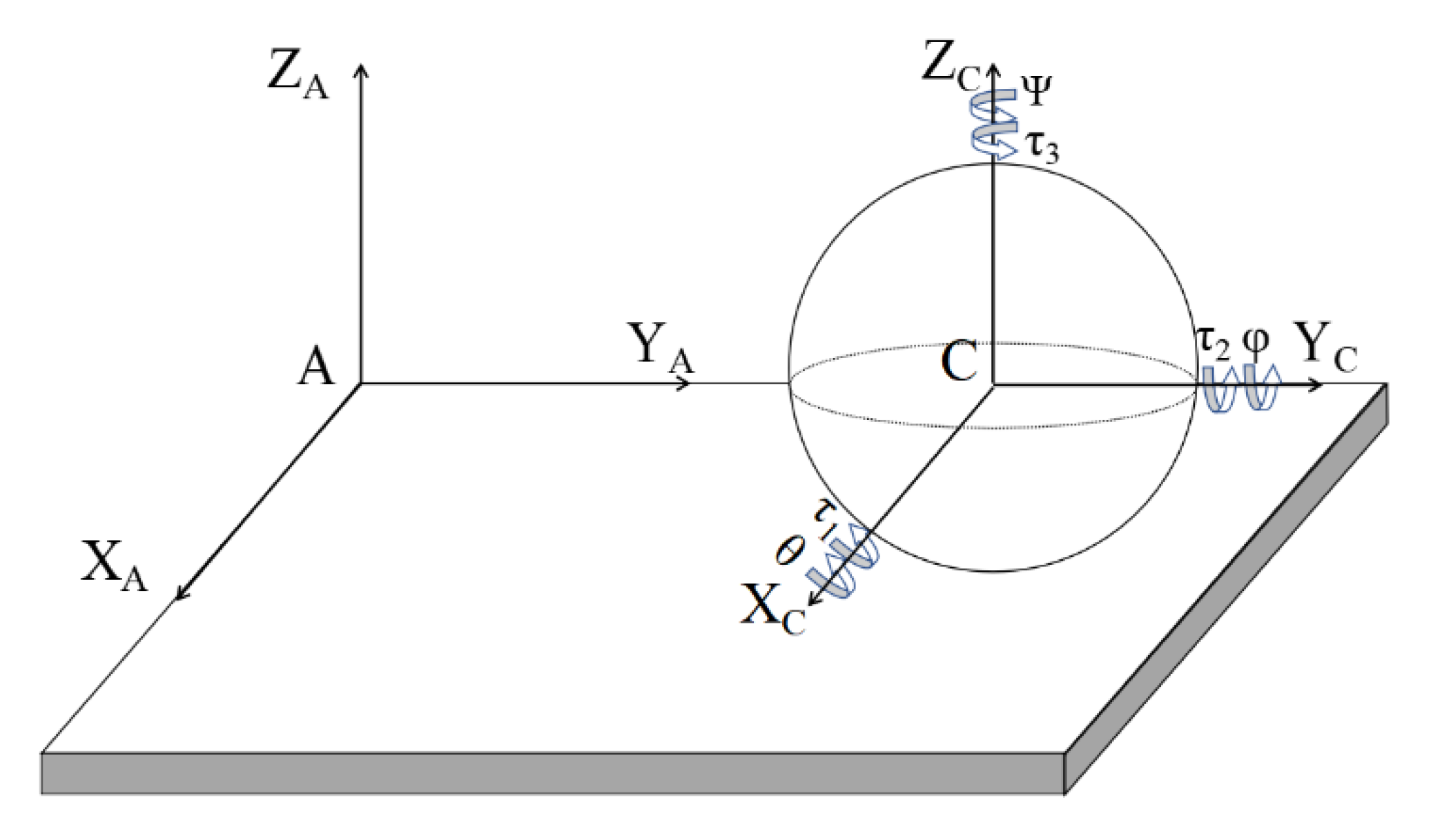
3. The Kinetic Analysis of the Rolling and Jumping Robot
A theoretical model based on the space coordinate system was established to analyze the influence of structural design parameters on the dynamic characteristics of the robot, which was of guiding significance to improve its motion performance. In addition, the physical meanings of the letters involved in the establishment of the dynamic model are shown in Table 1.
Table 1.
Parameters of the robot.
The space coordinate system of the robot was generally composed of a carrier coordinate system and ground coordinate system. The law of inertia applied to the ground coordinate system, which could be used to describe the position change of the robot, while the carrier coordinate system was a non-inertial coordinate system moving with the robot. In this coordinate system, the moment of inertia and the product of inertia were constant, which could easily describe the attitude change of the robot. In the process of the space motion of the robot, a spatial coordinate system was established, shown in Figure 10. The ground coordinate system was recorded as: ∑A(XAYAZA) and the carrier coordinate system was recorded as: ∑C(XCYCZC). Taking the motion starting point as the origin A of the ground coordinate system, it was specified that the vertical upward direction was +ZA, and the rolling forward direction of the robot at the starting time was +YA. The geometric center of the robot system was taken as the origin C of the moving coordinate system. The rolling forward direction of the robot at the current time was + YC. The vertical upward direction was +ZC. The components of the attitude angle in XC, YC and ZC axes were defined as θ, φ and Ψ. The components of the external torque vector in XC, YC and ZC axes were defined as τ1, τ2, τ3. In order to simplify the analysis of the problem, the robot was equivalent to a multibody system, and the following assumptions were made:
Figure 10.
Spatial coordinate system.
- The spatial motion of the robot follows the constraint condition of rigid body sliding free rolling;
- The shell is equivalent to a homogeneous thin-walled shell with uniform mass distribution;
- In the initial state, the centroid of the robot coincides with the geometric center;
- In the moving state, only the dynamic friction between the shell and the ground is considered, and the internal friction is ignored.
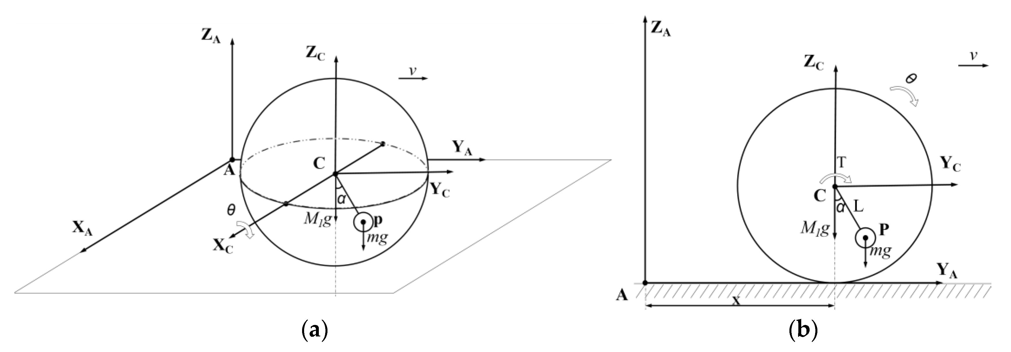
3.1. Rolling Dynamic Equation
The rolling motion of the rolling and jumping robot depends on the deflection of the eccentric mass to produce the driving force perpendicular to the ZC-XC plane as shown in Figure 11a. The plane where the simple pendulum moves was selected to simplify the dynamic model to describe the rolling dynamic characteristics of the robot. In addition, the simplified model consisted of two generalized coordinates on the plane α, x and a generalized force T as shown in Figure 11b. M1 is the mass of the remaining part without the counterweight; m is the mass of the counterweight, and the center of mass of counterweight is P.
Figure 11.
(a) Schematic diagram of rolling movement; (b) View of YAZA-plane of the schematic diagram of rolling movement.
This system was a two degrees of freedom system. The rolling and jumping robot purely rolled on the ground, and the moment t acted on point P. However, the input of the robot system was only the torque T, which was a typical underactuated system [16]. Its kinetic energy E and potential energy V were:
According to the second kind of Lagrange equation (Equation (3)) in generalized coordinates,
where, , is the generalized force. According to Equations (1)–(3), there is:
3.2. Steering Dynamics Equation
The robot steered in the form of sliding free rolling on the horizontal plane, shown in Figure 12. The included angle between the major shaft of the robot and the horizontal plane was β; the friction force in motion was f; the mass of the rolling module was m0; the center of mass was C; the distance between the center of mass and the geometric center of the shell was d; the counterweight mass was m; the distance between the limit position on both sides of the counterweight and the shape center was l; the length of the swing arm was L; the turning radius was r, and the geometric radius of the robot was R.
Figure 12.
(a) Schematic diagram of steering movement; (b) View of XCZC-plane of the schematic diagram of steering movement.
According to the triangular geometric relationship, the turning radius r can be approximately expressed as:
When the robot system is in a balanced state with a constant inclination angle, the components of the gravity moment generated by the counterweight and the rolling module along XC are MP and MC respectively, which can be obtained from the movement balance condition:
Since MC is 0:
Take the moment along the XC-axis:
According to Equations (5)–(8), in the steering movement, r and L meet the following constraints:
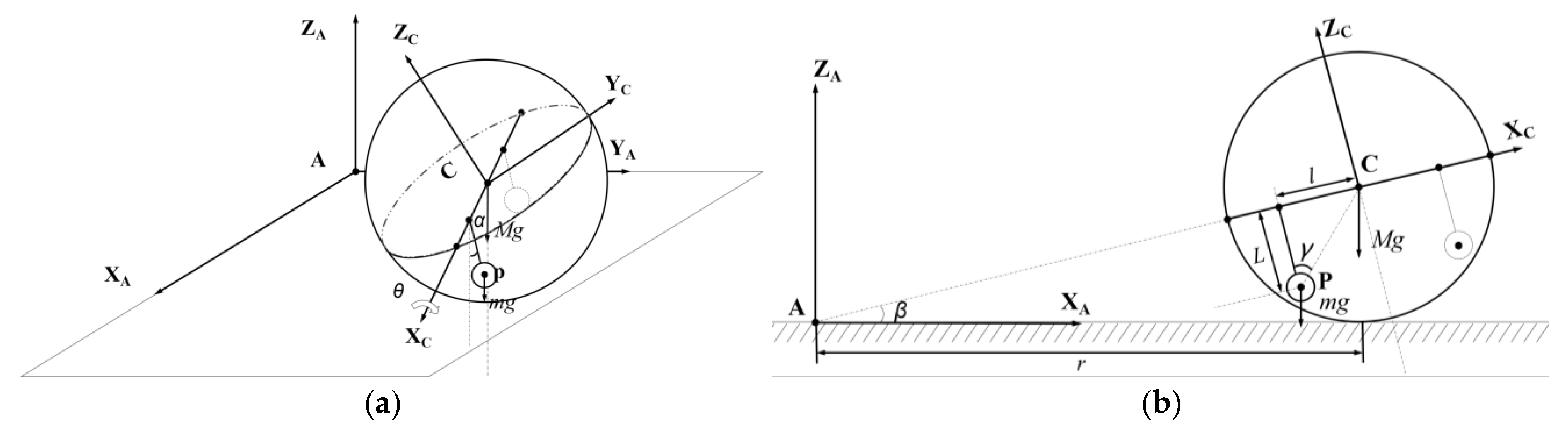
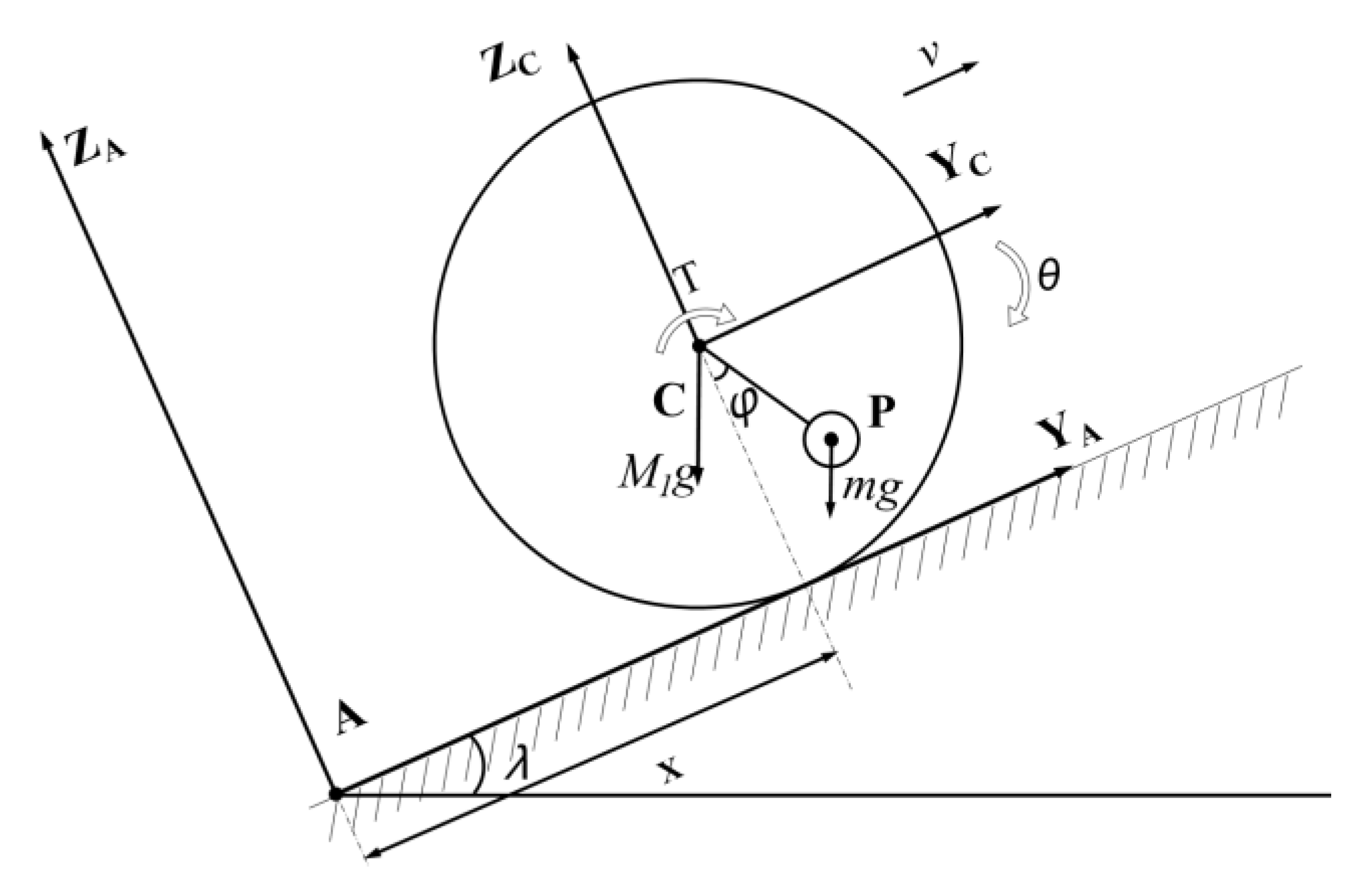
3.3. Climbing Dynamics Equation
Climbing motion refers to the upward rolling motion of the robot along the slope with a certain inclination angle to the horizontal plane. The climbing angle is a basic index to describe the climbing performance of robot. The maximum climbing angle is used to measure the ability of robot to climb over obstacles. Based on the theory of geometry and dynamics, the dynamic equation of robot climbing was established through the second kind of Lagrange equation.
The robot climbed the slope without relative sliding along the inclined plane with angle λ, shown in Figure 13. The pendulum mass was m; the center of mass was fixedly connected with the geometric center of the shell through a light rod with a length of L; the approximate equivalent mass of the remaining part without the pendulum was M1, and the geometric radius of the robot was R; At that current moment, the deflection angle of the pendulum was φ.
Figure 13.
Schematic diagram of climbing.
When the robot rolls upward along the slope, the rolling constraints without sliding and bouncing can be expressed as:
Since the linear velocity v is the first derivative of the displacement x with respect to time, and the angular velocity is the first derivative of angle Ψ to time, integrating Equation (10) provides:
According to Equation (11), in the process of the robot rolling upward along the slope, the position and attitude of t at any time can be uniquely determined by the rolling angle Ψ of shell and the swing angle φ.
According to the Lagrange equation (Equation (3)), the robot system was divided into two parts: a mean thin-walled shell and a pendulum. The kinetic energy and potential energy of each part were calculated respectively, and then the kinetic energy and potential energy of the system were solved by superposition.
The position coordinates of the robot were expressed as:
where: is the vector from the coordinate origin A to the center of the sphere and and are unit vectors of ground coordinates.
From Equation (12), the coordinate representation of the center of mass of the pendulum in the ground coordinate system was obtained:
where: is the vector form from the pendulum center of mass to center of the sphere.
According to Formulas (11) and (12):
According to Formulas (11) and (13):
We calculated the derivative of time t on both sides of Equations (14) and (15), so the velocity vector of the ball center and the velocity vector of the pendulum were obtained as follows:
The kinetic energy EK1 of the shell included the translational kinetic energy Ek1t of the translational motion of the shell and the rotational kinetic energy Ek1r of the shell. According to Equation (16), the translational kinetic energy of the shell was:
If the moment of inertia of the shell was IM, the rotational kinetic energy of the shell was:
Therefore, the kinetic energy of the shell was expressed as:
The kinetic energy of the pendulum included the translational kinetic energy and rotational kinetic energy of the pendulum, which were obtained from Equation (17). The translational kinetic energy of the pendulum was:
If the rotational momentum of the pendulum was Im, the rotational kinetic energy of the pendulum was:
Therefore, the kinetic energy of the pendulum was expressed as:
where:
When the horizontal plane was selected as the zero-potential energy plane, the potential energy of the shell was expressed as:
The potential energy of the pendulum was expressed as:
The potential energy of the robot system was:
The Lagrange operator L of the robot was:
where:
Ignoring the internal friction of the system, the Lagrange equation of the second kind of the robot system was expressed as follows:
By introducing Equation (27) into Equation (28), the dynamic equation of the climbing motion of the robot was obtained:
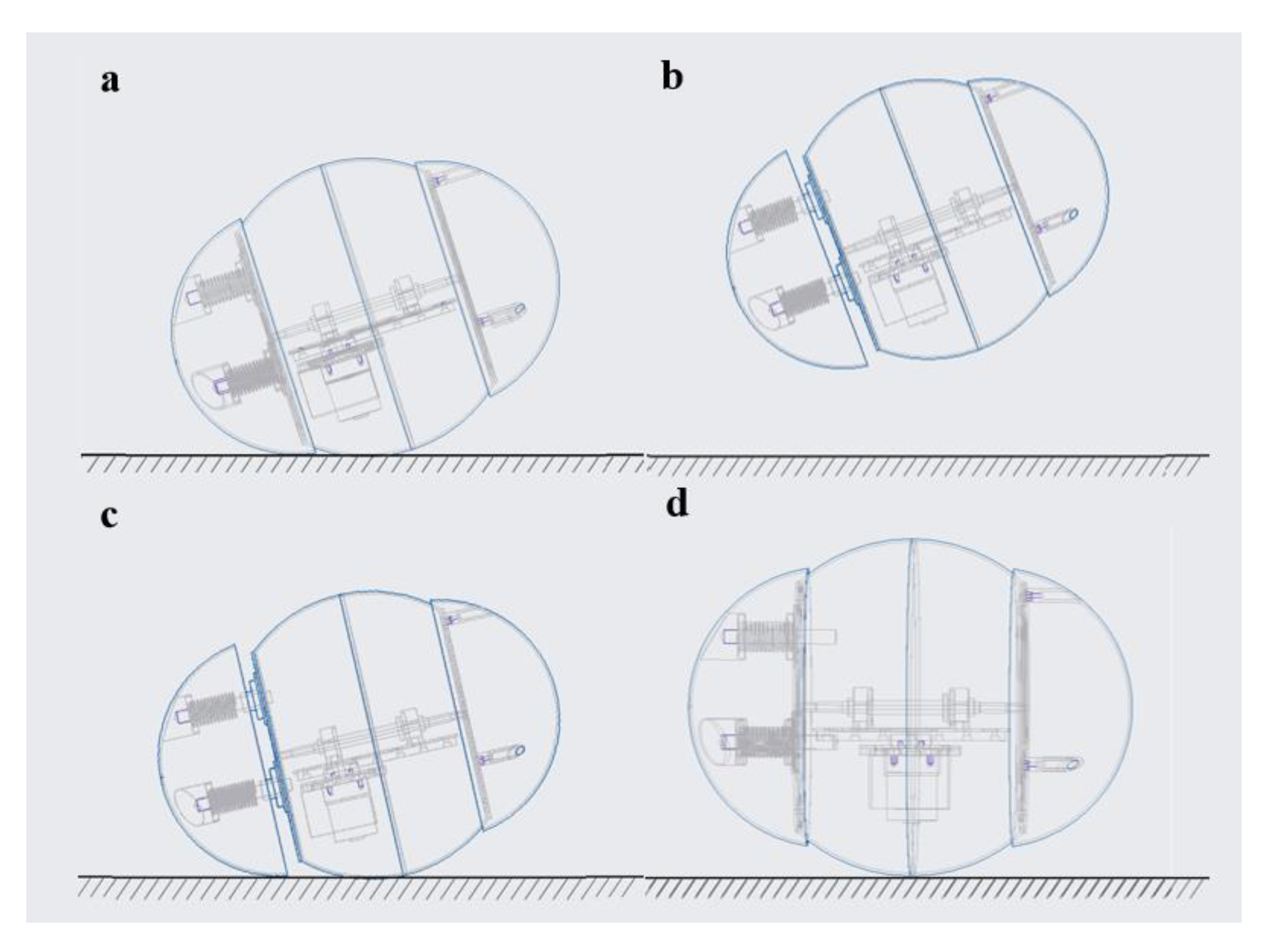
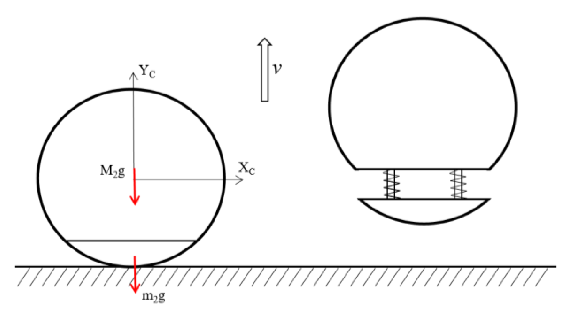
3.4. Jumping Dynamics Equation
In order to simplify the jumping motion, this paper only discusses the vertical upward jumping of the robot, shown in Figure 14.
Figure 14.
Jumping motion diagram.
The mass of the energy storage end of bouncing spring of the robot is m2 and the mass of the rest is M2; the jumping spring coefficient is k; the energy storage compression distance is D, and there are three energy storage springs in total. According to the momentum theorem and energy conservation:
4. Performance Test of the Rolling and Jumping Robot
The motion flexibility and obstacle-crossing ability of the rolling and jumping robot were tested. As shown in Figure 15, the robot could avoid obstacles, such as crossing obstacles on flat surfaces (Figure 15a) or escaping from hollows (Figure 15b), by adjusting the robot’s traveling posture or switching its motion modes through the wireless control module, the robot was adaptable to complex environments. In addition, the specific motion parameters of the robot in different motion modes were also tested, including rolling speed, turning radius, climbing angle, and jumping height.
Figure 15.
Obstacle avoidance function of the rolling and jumping robot: (a) Obstacle avoidance function by rolling motion; (b) Obstacle avoidance function by jumping motion.
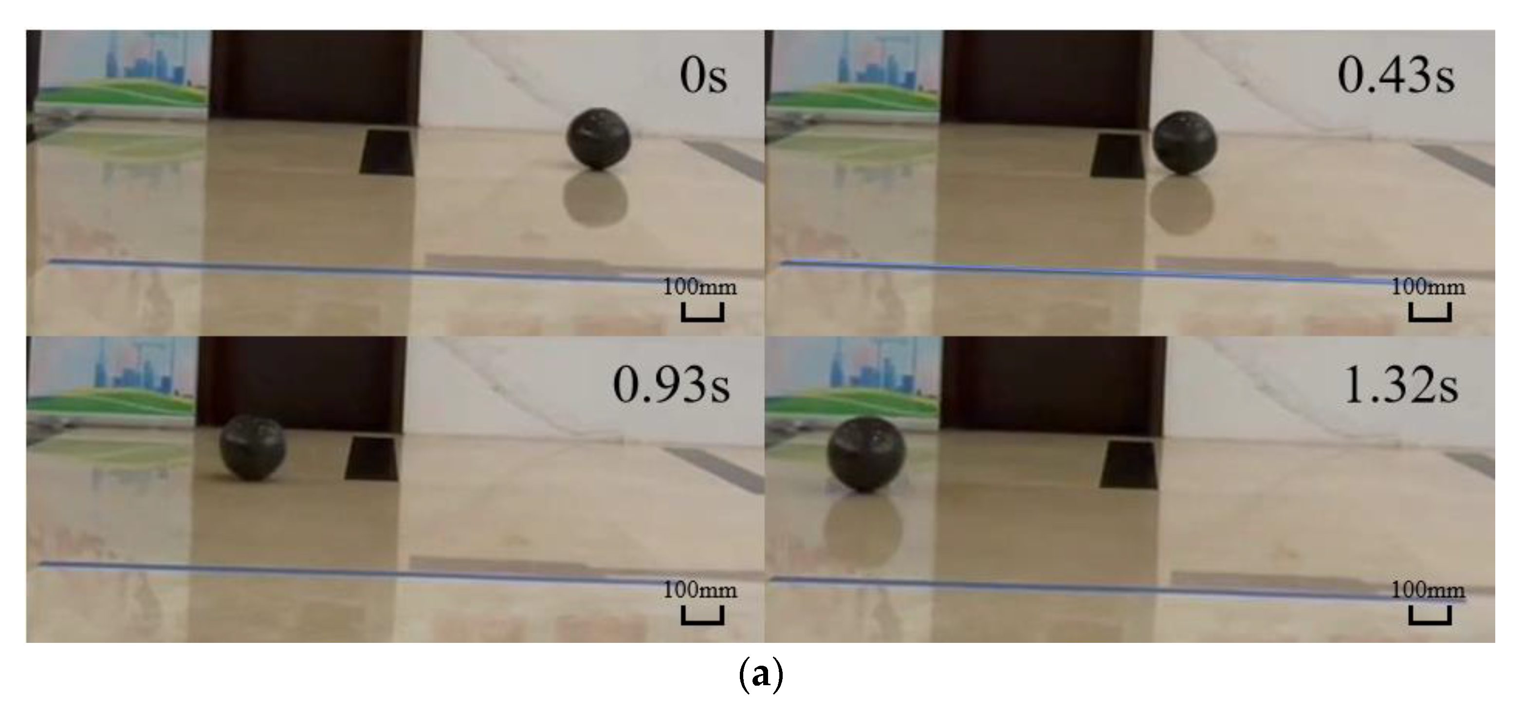
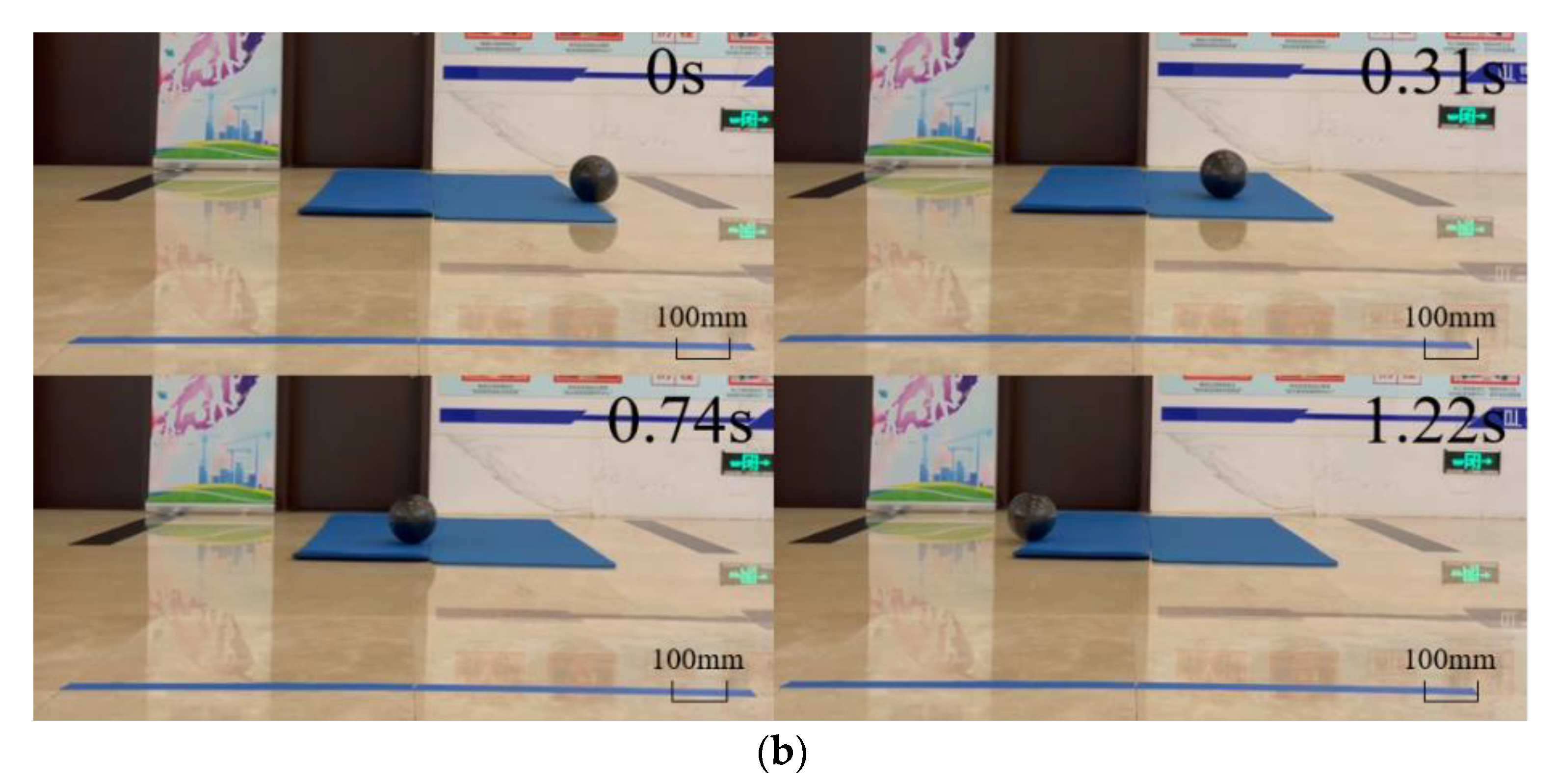
4.1. Rolling Performance
4.1.1. Rolling Speed Test
The maximum rolling speed of the robot on a hard and flat surface (90 HA) was measured. In addition, the speed attenuation of the robot when it rolled through a loose surface (25 HD) at maximum speed was also characterized, as shown in Figure 16.

Figure 16.
Rolling motion of the robot: (a) hard and flat surface (90 HA); (b) loose surface (25 HD).
At full power, the maximum rolling speed of the robot was about 1229.5 mm/s, which decreased to 1147.5 mm/s when passing over loose road surfaces.
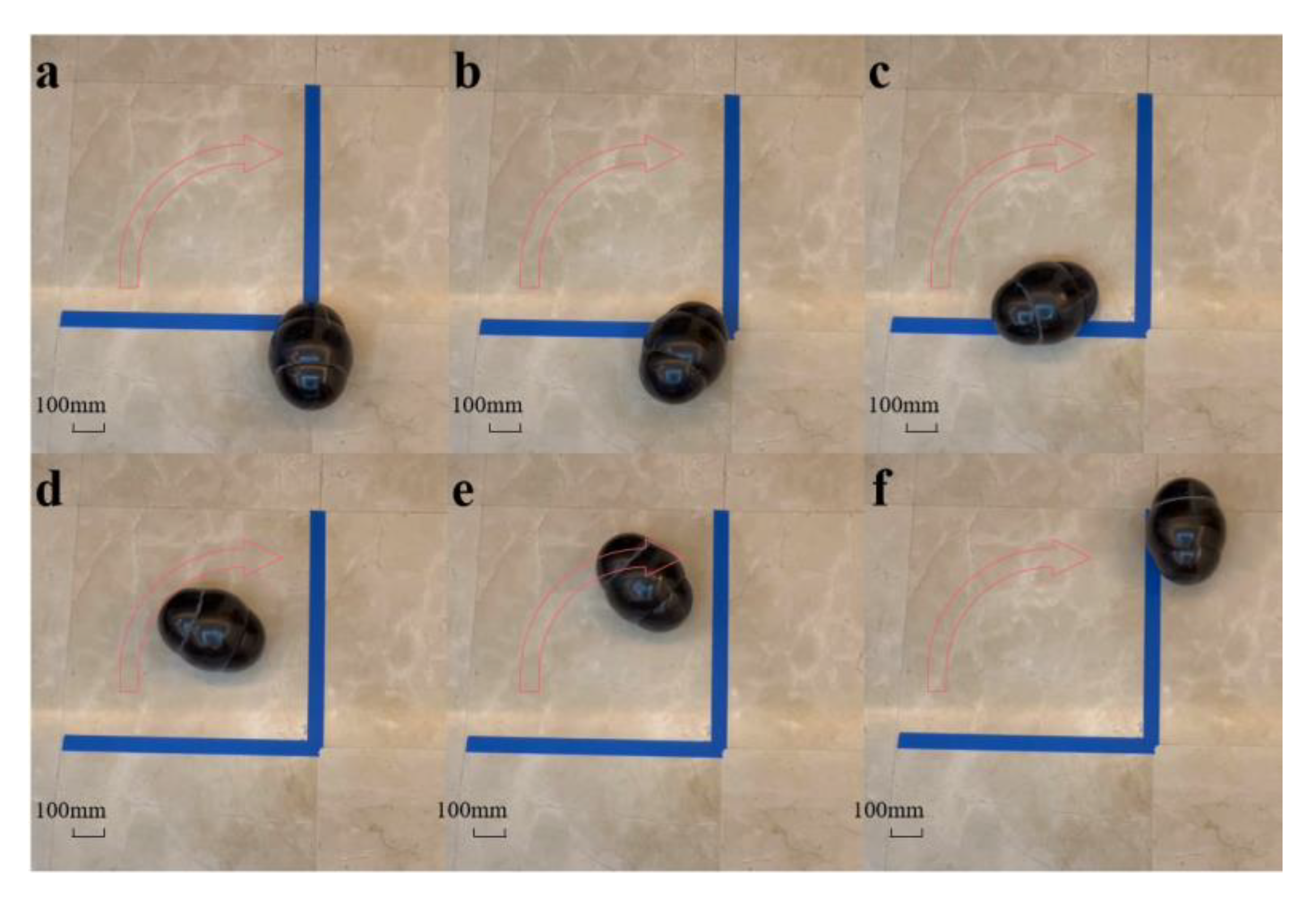
4.1.2. Turning Radius Test
The counterweight was moved to the limit position to make the robot complete a semicircle trajectory, shown in Figure 17. We marked the gap between the two tiles for reference to track the turning trajectory of the robot.
Figure 17.
Turning motion of the robot.
However, on the premise that the counterweight was kept at the limit position, the turning radius would increase with the increase in rolling speed. Therefore, it was necessary to lower the motor output to a power that only allowed the robot to meet the minimum motion speed. After many tests and measurements, a large amount of reliable data was obtained, and the minimum turning radius of the robot was close to 300 mm.
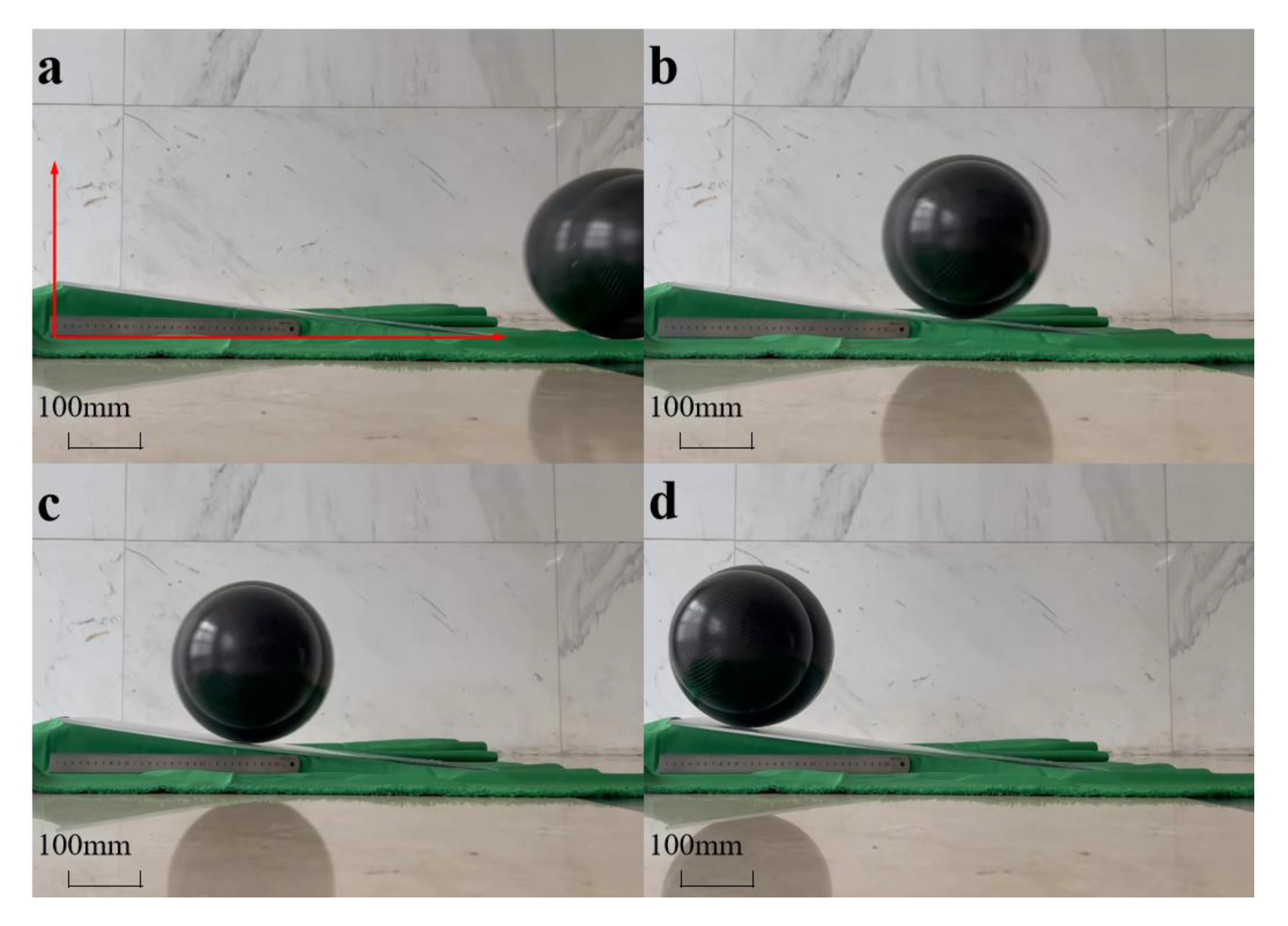
4.1.3. Climbing Performance Test
We treated the slope of the test platform to avoid slipping between the spherical shell and the slope, and the climbing performance of the robot was tested at the maximum speed, shown in Figure 18.
Figure 18.
Climbing motion of the robot.
In this paper, we used the climbing angle to characterize the climbing ability of the robot. Considering the energy loss caused by many factors, we dynamically adjusted the height of the test platform, and finally obtained the maximum climbing angle of 11.31°.
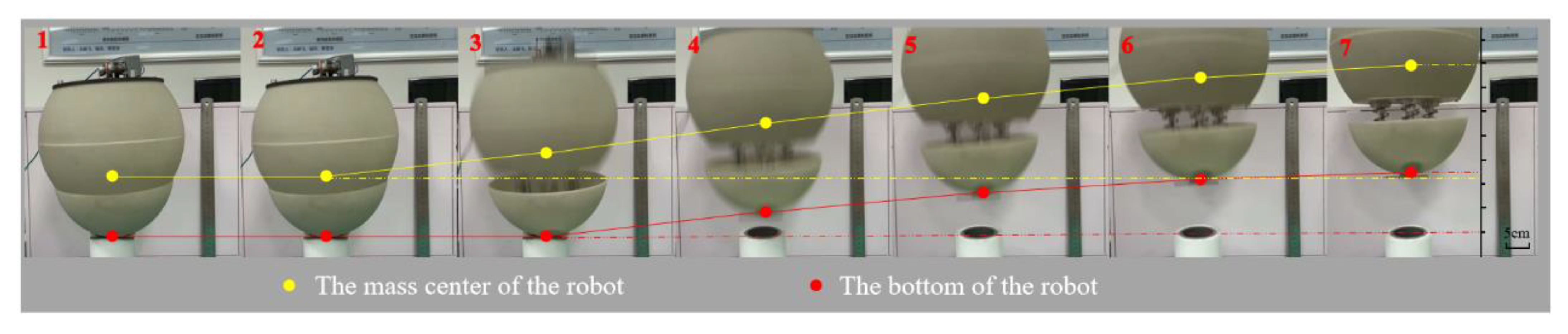
4.2. Jumping Performance
In order to characterize the maximum jumping ability provided by the current jumping module, and then provide reference for the selection of parts in the subsequent optimization work, the robot was placed vertically to test its vertical jumping performance, which could effectively reduce the test error caused by the slippage between the spherical shell and the ground. The trajectory of the mass center and the bottom of the robot were represented by yellow and red lines, and the jumping heights were 210 mm and 130 mm, respectively, shown in Figure 19.
Figure 19.
Jumping motion of robot.
4.3. Comparison between the Theoretical Value and Test Value
We developed the robot prototype and tested the quality, size, and other parameters of all parts of the robot, shown in Table 2. Substituting these values into the Equations (4), (9), (29) and (30), the rolling speed of the theoretical model was 1327 mm/s, the turning radius 263 mm, the climbing angle was 13.67°, and the jumping height (center of mass) was 254 mm. Based on these, the motion performance of the robot prototype was also tested and evaluated by comparing with the theoretical model.
Table 2.
Parameters of the prototype.
As shown in Table 3, there was a certain relative error between the measured data and the theoretical data. Considering that the acquisition of theoretical data came from the simplified treatment of the model, and the energy loss caused by mechanical friction, transmission efficiency, and other factors during the movement of the actual prototype were not taken into account, the relative error between the two was considered to be within an acceptable range. The establishment and analysis of the theoretical model were reliable and reasonable, and the actual prototype design based on the theoretical model was feasible.
Table 3.
Key motion characteristics of the theoretical model and prototype.
5. Conclusions
A rolling and jumping compound motion robot was designed and analyzed, which integrated a rolling motion module based on a single pendulum structure and a jumping module based on springs. In the design process of the rolling motion module, in order to reduce the overall weight of the rolling and jumping robot and improve the motion performance of the rolling and jumping robot, a new single pendulum structure was designed based on the classical single pendulum rolling robot. The parts inside the rolling and jumping robot were fully utilized, which not only realized their original functions, but also acted as a part of the pendulum. Therefore, no additional weight was needed to act as the pendulum of the rolling and jumping robot, which reduced the weight of the whole robot and improved rolling performance. The kinematic parameters such as rolling speed, turning radius, climbing angle, and jumping height of the robot were calculated by establishing a theoretical model. Meanwhile, the motion performance of the actual prototype was tested; the results showed that the robot had flexible rolling and jumping abilities and adapted to complex terrain by switching between the two motion modes. The actual motion parameters of the robot were compared with the theoretical values obtained by dynamic modeling. Taking the energy loss caused by mechanical friction, transmission efficiency, and other factors into account, the relative errors between the theoretical data and the measured data were considered to be a reasonable range, which shows the feasibility of the design scheme of the rolling and jumping robot proposed in this paper.
In the future, we will focus on optimizing the internal structure of the robot, including reasonable arrangement of control modules and reduction in redundant counterweights, to improve the stability of the robot. In addition, we plan to adjust the design of the jumping module and integrate the jumping module containing the inertia block and coil spring inside the robot’s spherical shell. By transforming the elastic potential energy stored in the coiling spring into the kinetic energy of the inertial block, the inertia block will move quickly and then drive the robot to complete the jumping action.
Author Contributions
Conceptualization, B.L. (Bingyang Li) and H.W.; methodology, B.L. (Bingyang Li) and Y.Y.; software, F.W.; validation, B.L. (Bingyang Li), H.W. and Y.Y.; investigation, B.L. (Bin Luo); resources, Z.J.; data curation, B.L. (Bingyang Li) and H.W.; writing—original draft preparation, B.L. (Bingyang Li).; writing—review and editing, B.L. (Bingyang Li) and H.W.; supervision, P.W.; project administration, Y.Y. and P.W. All authors have read and agreed to the published version of the manuscript.
Funding
This research received no external funding.
Institutional Review Board Statement
Not applicable.
Informed Consent Statement
Not applicable.
Acknowledgments
This work was sponsored by the Qian Xuesen Youth Innovation Foundation and the Defense Science; Technology 173 Program Technical Field Fund(2019-JCJQ-JJ-459); National Natural Science Foundation of China (No. 91748209).
Conflicts of Interest
The authors declare no conflict of interest.
References
- Yanagida, T.; Mohan, R.E.; Pathmakumar, T.; Elangovan, K.; Iwase, M. Design and Implementation of a Shape Shifting Rolling–Crawling–Wall-Climbing Robot. Appl. Sci. 2017, 7, 342. [Google Scholar] [CrossRef] [Green Version]
- Hayat, A.A.; Elangovan, K.; Rajesh Elara, M.; Teja, M.S. Tarantula: Design, Modeling, and Kinematic Identifucation of a Quadruped Wheeled Robot. Appl. Sci. 2019, 9, 94. [Google Scholar] [CrossRef] [Green Version]
- Chen, X.; Wu, Y.; Hao, H.; Shi, H.; Huang, H. Tracked Wall-Climbing Robot for Calibration of Large Vertical Metal Tanks. Appl. Sci. 2019, 9, 2671. [Google Scholar] [CrossRef] [Green Version]
- Hwang, M.C.; Liu, F.; Yang, J.; Lin, Y. The Design and Building of a Hexapod Robot with Biomimetic Legs. Appl. Sci. 2019, 9, 2792. [Google Scholar] [CrossRef] [Green Version]
- Luo, B.; Li, B.; Yu, Y.; Yu, M.; Ma, J.; Yang, W.; Wang, P.; Jiao, Z. A Jumping Robot Driven by a Dielectric Elastomer Actuator. Appl. Sci. 2020, 10, 2241. [Google Scholar] [CrossRef] [Green Version]
- Mukherjee, R.; Minor, M.A. A simple motion planner for a spherical mobile robot. In Proceedings of the IEEE/ASME International Conference on Advanced Intelligent Mechatronics, Atlanta, GA, USA, 19–23 September 1999; pp. 896–901. [Google Scholar]
- Javadi, A.A.H.; Mojabi, P. Introducing August: A novel strategy for an omnidirectional spherical rolling robot. In Proceedings of the ICRA’02 IEEE International Conference on Robotics and Automation, Washington, DC, USA, 11–15 May 2002; pp. 3527–3533. [Google Scholar]
- Mansour, N.A.; Jang, T.; Baek, H.; Shin, B.; Ryu, B.; Kim, Y. Compliant closed-chain rolling robot using modular unidirectional SMA actuators. Sens. Actuators A Phys. 2020, 310, 112024. [Google Scholar] [CrossRef]
- Davoodi, F.; Davoudi, F. Design for the Structure and the Mechanics of Moballs; NASA Tech Briefs, 2012; Volume 36, pp. 66–68.
- Burkhardt, M.R.; Davoodi, F.; Burdick, J.W.; Davoudi, F. Energy harvesting analysis for moball, a self-propelled mobile sensor platform capable of long duration operation in harsh terrains. In Proceedings of the IEEE International Conference on Robotics and Automation (ICRA), Hong Kong, China, 31 May–7 June 2014; pp. 2665–2672. [Google Scholar]
- Davoodi, F.; Burdick, J.W.; Rais-Zadeh, M. Moball network: A self-powered intelligent network of controllable spherical mobile sensors to explore solar planets and moons. In Proceedings of the AIAA SPACE Conference and Exposition, San Diego, CA, USA, 4–7 August 2014; pp. 1–9. [Google Scholar]
- Yoshimitsu, T.; Kubota, T.; Nakatani, I.; Adachi, T.; Saito, H. Micro-hopping robot for asteroid exploration. Acta Astronaut. 2003, 52, 441–446. [Google Scholar] [CrossRef]
- Kovač, M.; Schlegel, M.; Zufferey, J.-C.; Floreano, D. Steerable miniature jumping robot. Auton. Robot. 2009, 28, 295–306. [Google Scholar] [CrossRef] [Green Version]
- Zhang, J.; Song, G.; Li, Z.; Zhang, Y.; Qiao, G.; Song, A. Locomotion Performance Analysis of a Foldable Wheeled Jumping Robot: Fold Jumper. Robot 2014, 2, 250–256. [Google Scholar]
- Zhang, Y.; Huang, Z.; Han, L.; Gu, C.; Zhang, W. Design and Analysis of the Crawling and Rolling Characteristics of the Crawling and Rolling Robot for the Lunar Extreme Terrain. J. Mech. Eng. 2021, 57, 35–48. [Google Scholar]
- Wang, P.-F.; Wang, X.; Li, M.-T.; Sun, L.-N. Dynamics analysis of a micro-spherical robot. J. Harbin Inst. Technol. 2010, 9, 1398–1402. [Google Scholar]
Publisher’s Note: MDPI stays neutral with regard to jurisdictional claims in published maps and institutional affiliations. |
© 2021 by the authors. Licensee MDPI, Basel, Switzerland. This article is an open access article distributed under the terms and conditions of the Creative Commons Attribution (CC BY) license (https://creativecommons.org/licenses/by/4.0/).