Abstract
Research on underground coal mines has primarily focused on the stability of roadways. Mining activities lead to significant damage to the surrounding rocks and also degrade the support to the roadways. Considering the 21309 roadway of the Huojitu coal mine as a case study, this work comprehensively analyzed the characteristics of the surrounding rock using three methods: theoretical calculations, FLAC3D numerical modeling, and field observations. The results indicate that, under the influence of secondary mining, the failure range and stress concentration degree of the surrounding rock are considerably higher than those under the influence of primary mining. In this case, the maximum damage range in the surrounding rock can reach 1.8 m, the maximum principal stress can reach 19.82 MPa, and the ratio of the maximum principal stress to the minimum principal stress can reach 1.95. According to the results, the previous support design for roadways was optimized and applied in the field. Field monitoring revealed that the roadway deformation was effectively controlled, and the optimized support design was safe and reliable. This study is expected to serve as a reference for support designs or optimization under similar geological conditions.
1. Introduction
To solve the problems associated with transportation, ventilation, and gases, many underground coal mines in China still employ a two-entry longwall panel system [1,2]. The roadway in this system is subjected to two mining influences and strong ground pressure behaviors; consequently, roadway maintenance is more difficult [3,4]. Therefore, considerable research has been devoted toward the failure characteristics and control technology of roadways in two-entry longwall panel systems.
In the field of roadway surrounding rock control, many scholars have proposed roadway support theories and technologies. For instance, Paul et al. proposed and verified a rock mass rating (RMR)-based bolt design considering the underground coal mines in India [5]. Sun et al. confirmed that high-constant-resistance anchor cables can effectively control roadway deformation [6]. Kang et al. proposed a rock bolt system for the ground reinforcement of longwall roadways within soft rock masses and successfully applied this approach in the field [7]. Yang et al. proposed a novel “bolt-cable-mesh-shotcrete + shell” combined support for a ventilation roadway [8]. Majcherczyk et al. confirmed the effectiveness of combined yielding steel arch with rock bolt support systems under different mining conditions [9]. Mahdevari et al. employed artificial neural networks (ANNs) to predict the stability conditions of longwall roadways based on roof displacements [10]. To obtain a qualified support design, it is necessary to first analyze the failure of the roadway surrounding rock. After realizing the support design, its rationality must be verified through field applications.
Failures in the surrounding rock of roadways are primarily caused by the distribution of the plastic zone in the rock. Roadways are affected by mining, which, in turn, results in stress concentration in the surrounding rock and plastic failure of the rock masses [11,12,13]. Thus, many scholars have conducted extensive research on the plastic zone and stress distribution law of roadways; various formulas for calculating the plastic zone in roadway surrounding rocks have also been proposed [14,15]. Such research has enriched the theoretical system of surrounding rock control. Furthermore, scholars have used different experimental and numerical methods to collate a large number of field application cases [16,17,18,19,20]; this is also expected to serve as a reference for future research in this field. Researchers have reported that the principal stress has a significant influence on the stability of roadway surrounding rocks [21,22,23,24]. Therefore, when studying the stability of roadway surrounding rocks, it is necessary to analyze the influence of the principal stress on the distribution of the plastic zone.
Many research methods have been employed in these studies, which provide a strong basis for the failure characteristics and control technology of roadways in two-entry longwall panel systems. However, for the same problem, the research conclusions when using different research methods are not entirely identical. To address this discrepancy, in this study, three methods were used: a calculation formula for the roadway plastic zone, fast Lagrangian analysis of continua 3D (FLAC3D) numerical modeling, and field observation employing broken rock zone detection. This work aimed to obtain comprehensive and thorough research results, which are expected to serve as a reference for the control of roadway surrounding rocks under similar geological conditions.
2. Engineering Background
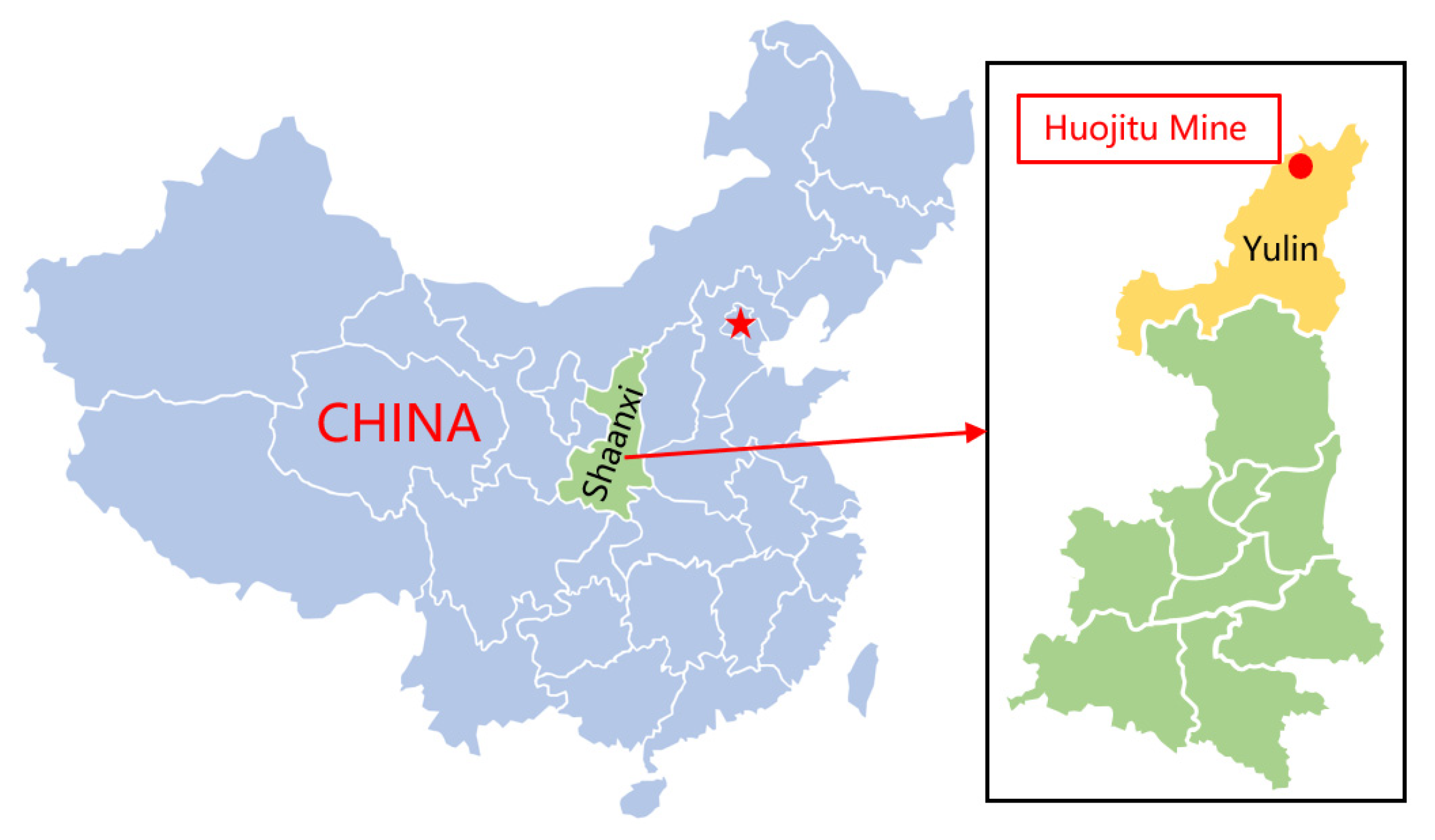
The experimental site considered in this study was the 21309 roadway of the Huojitu coal mine. The Huojitu coal mine is owned by the China Shenhua Shendong Coal Group Corporation Limited. It is located on the bank of the Ulan Mulun River at the southern end of Daliuta town in Shenmu County, Shaanxi Province, China. The annual production capacity of the Huojitu coal mine is 5 million tons, the minefield area is 63 km2, the geological reserves are 950 million tons, and the recoverable reserves are 624 million tons. Its location is presented in Figure 1.
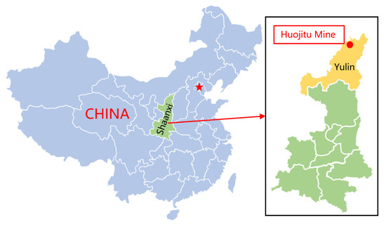
Figure 1.
Location of the Huojitu coal mine.
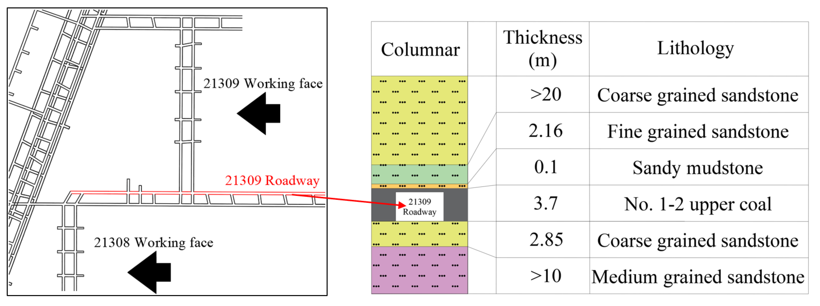
The 21309 roadway is located in the No. 1–2 upper coal seam, with a buried depth of 120 m. The thickness of the No. 1–2 upper coal seam in the Huojitu coal mine is 2.95–4.16 m, with an average thickness of 3.7 m. The dip angle of the coal seam is nearly horizontal, the structure is relatively simple, and it generally does not contain coal gangue. The thickness of the immediate roof is 0.94–3.4 m, with an average of 2.16 m. It is mainly composed of fine-grained sandstone, and there is a false roof with a thickness of 0.1 m in some areas. The basic roof is mainly coarse-grained sandstone, and some areas are siltstone or sandy mudstone. The immediate floor is mainly coarse-grained sandstone, with a thickness of 0.7–9.54 m and an average of 2.85 m; the basic floor is mainly medium-grained sandstone, and some areas are fine-grained sandstone or siltstone. The 21309 roadway was used as the material haulage roadway of the 21308 working face and the coal haulage roadway at the 21309 working face. Thus, it is affected by the mining influences of the two working faces. The location of the 21309 roadway and a generalized stratigraphy column are presented in Figure 2.
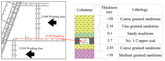
Figure 2.
Location of the 21309 roadway and generalized stratigraphy column.
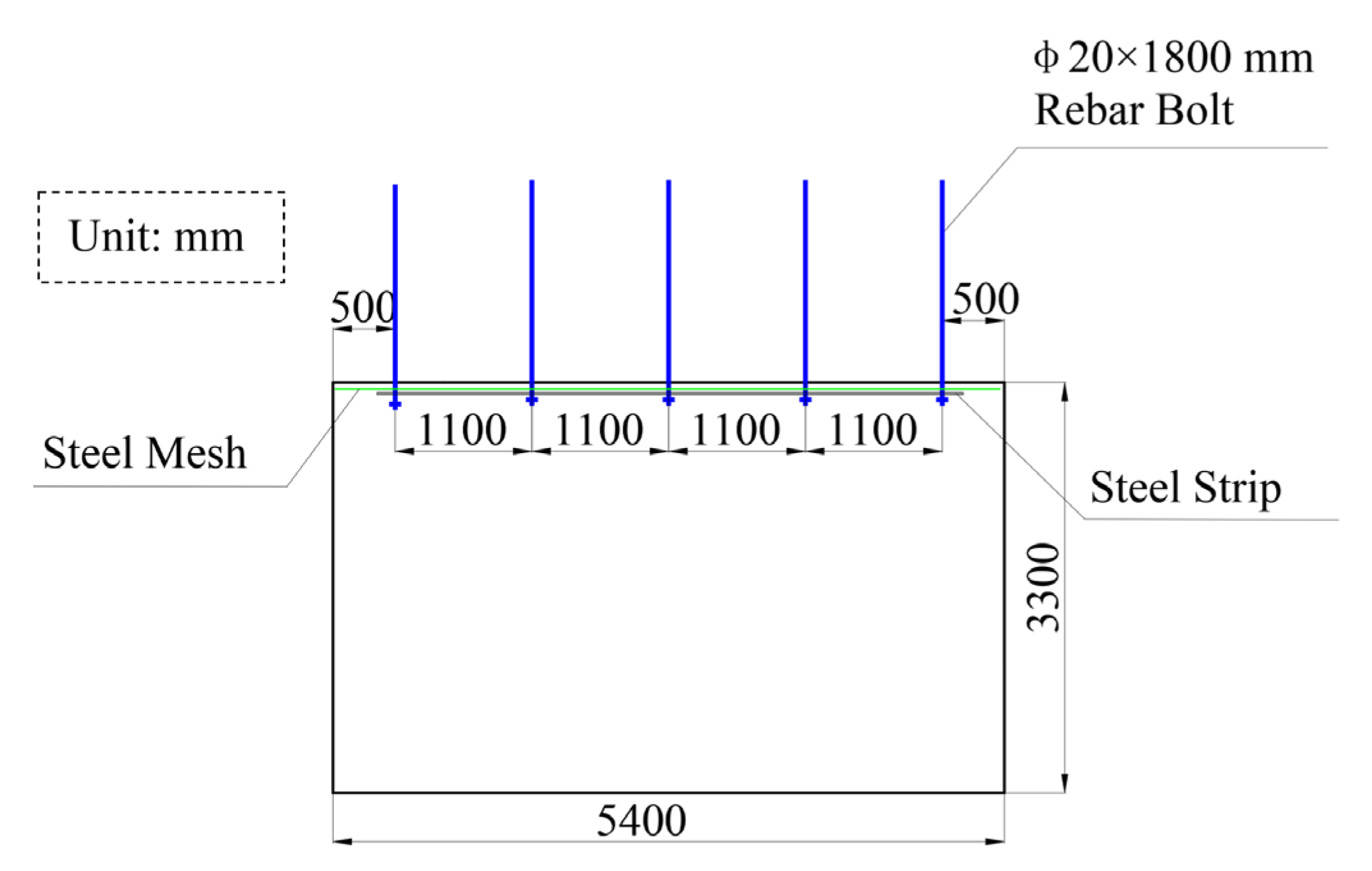
With regard to design dimensions, the 21309 roadway has a width of 5.4 m and a height of 3.3 m. Its cross section was designed to be rectangular, and the roadway lies along the coal seam floor. The average mining height of the 21308 working face is 3.7 m, and the length of the working face is 340 m. The design size of the coal pillar between working faces is 15 m. The previous support design for the roadway was based on the engineering analogy method; in other words, the support design of adjacent mines with similar geological conditions was adopted. The previous support design for the 21308 roadway is illustrated in Figure 3. The roof is supported by a rebar bolt, steel mesh, and steel strip. Five rebar bolts were arranged in each row, with a diameter of 20 mm, length of 1800 mm, spacing of 1100 mm, and row spacing of 1200 mm.
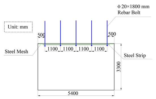
Figure 3.
Previous support design.
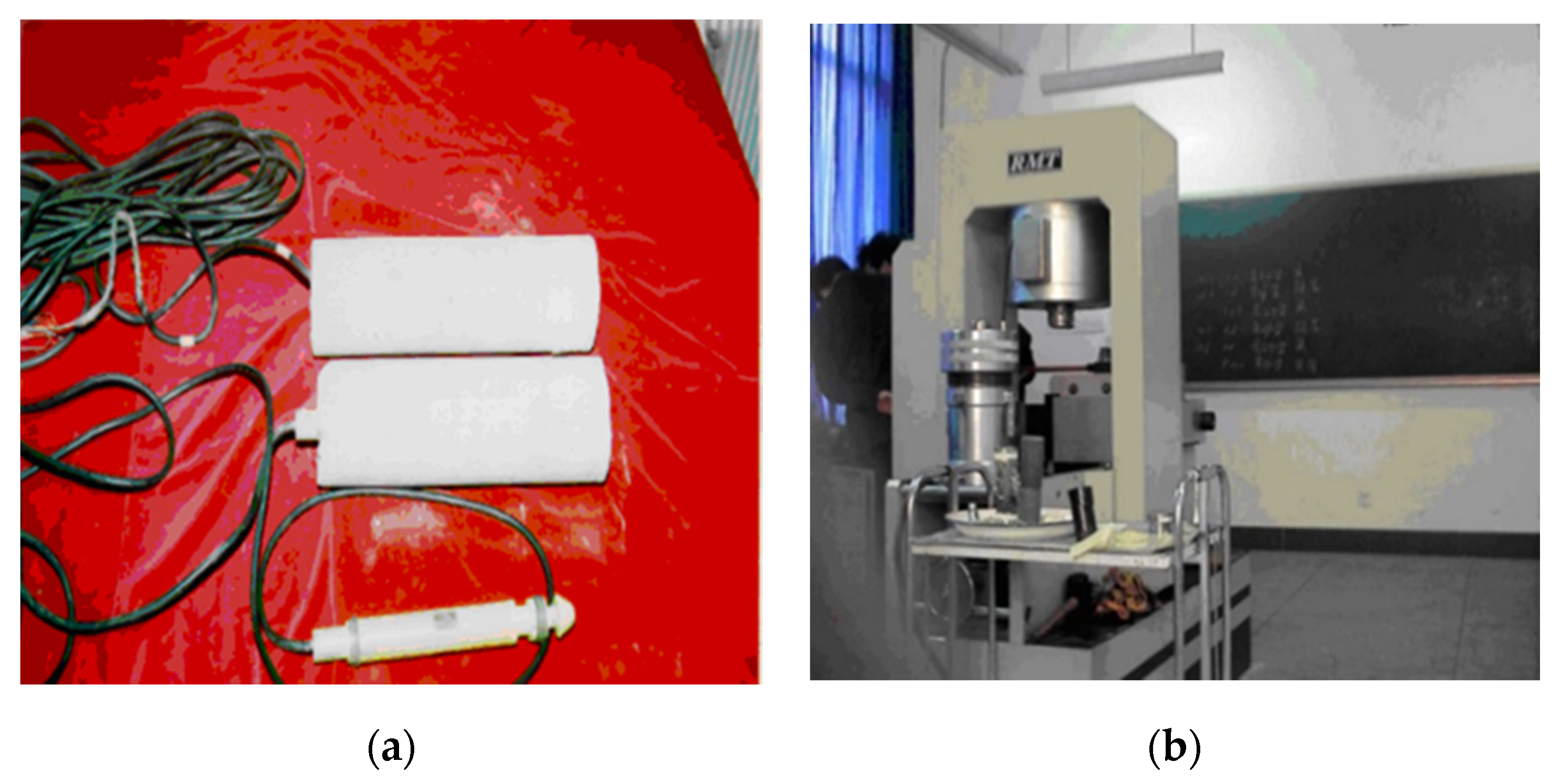
To elucidate the rock mechanics parameters of the surrounding rock of the 21309 roadway in the Huojitu mine, two groups of roof and floor rock samples of the No. 1–2 upper coal seam with a length of 12.8 m were obtained at the open-off cut of 21305(2) working face. The obtained rock samples were processed into standard sample sizes and tested in the laboratory. This testing process is presented in Figure 4, and the obtained rock mechanical parameters are listed in Table 1.
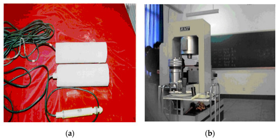
Figure 4.
Rock mechanics parameter test: (a) rock samples; (b) RMT-150B electro-hydraulic servo testing machine.

Table 1.
Rock mechanical parameters.
3. Methodology
3.1. Theoretical Calculation
The rock mass in which the mining roadway is located can be categorized as a heterogeneous, anisotropic medium. Currently, it is difficult to accurately analyze the stress in the roadway surrounding rock in this type of rock mass using mechanics and mathematics. Therefore, the calculations need to be simplified. For several decades, the plastic zone radius of a circular roadway has been typically determined using the Kastner formula as follows:
However, roadways are often subjected to bidirectional, unequal pressure fields. Based on the actual stress environment of the surrounding rock of a roadway, the theory of elastic mechanics, and the Mohr–Coulomb criterion, Ma et al. [25,26] derived the boundary equation for the plastic zone of the surrounding rock of a circular roadway under the condition of bidirectional, unequal pressure.
where λ is the lateral pressure coefficient; r is the radius of the roadway; R0 is the distance from the boundary of the plastic zone to the center of the roadway; θ represents the polar coordinates of any point in the roadway; C and φ are the cohesion and internal friction angle of the surrounding rock, respectively; P is the vertical stress.
In this study, the abovementioned two formulas were used to calculate the plastic zone of the roadway surrounding rock, and the calculation results were compared and analyzed.
3.2. Field Observations
Broken rock zone detection is used to predict the failure of the surrounding rock based on the different propagation velocities of ultrasonic waves in different media. In this study, the Phd-2 multifunctional ultrasonic detector developed by the China Coal Research Institute, as shown in Figure 5, was used for broken rock zone detection. This instrument can analyze the internal structure of coal and assess its internal failure by testing the acoustic parameters of the coal.
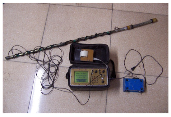
Figure 5.
Phd-2 multifunctional ultrasonic detector.
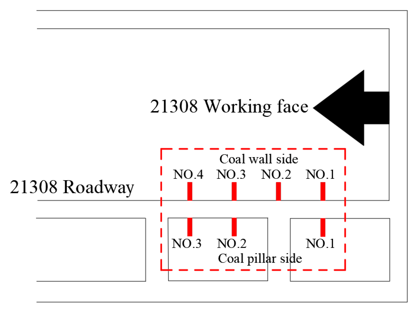
As the 21309 working face has not been mined, the 21308 roadway was selected as the location for broken rock zone detection. The 21308 and 21309 roadways are adjacent to each other, and their engineering geological conditions are almost identical. A total of four measuring stations, located 15, 25, 35, and 45 m away from the working face, were arranged. Each measuring station comprised two measuring holes located on the two sides of the roadway. The locations of these stations are shown in Figure 6.

Figure 6.
Arrangement of measuring stations for broken rock zone.
3.3. Numerical Modeling
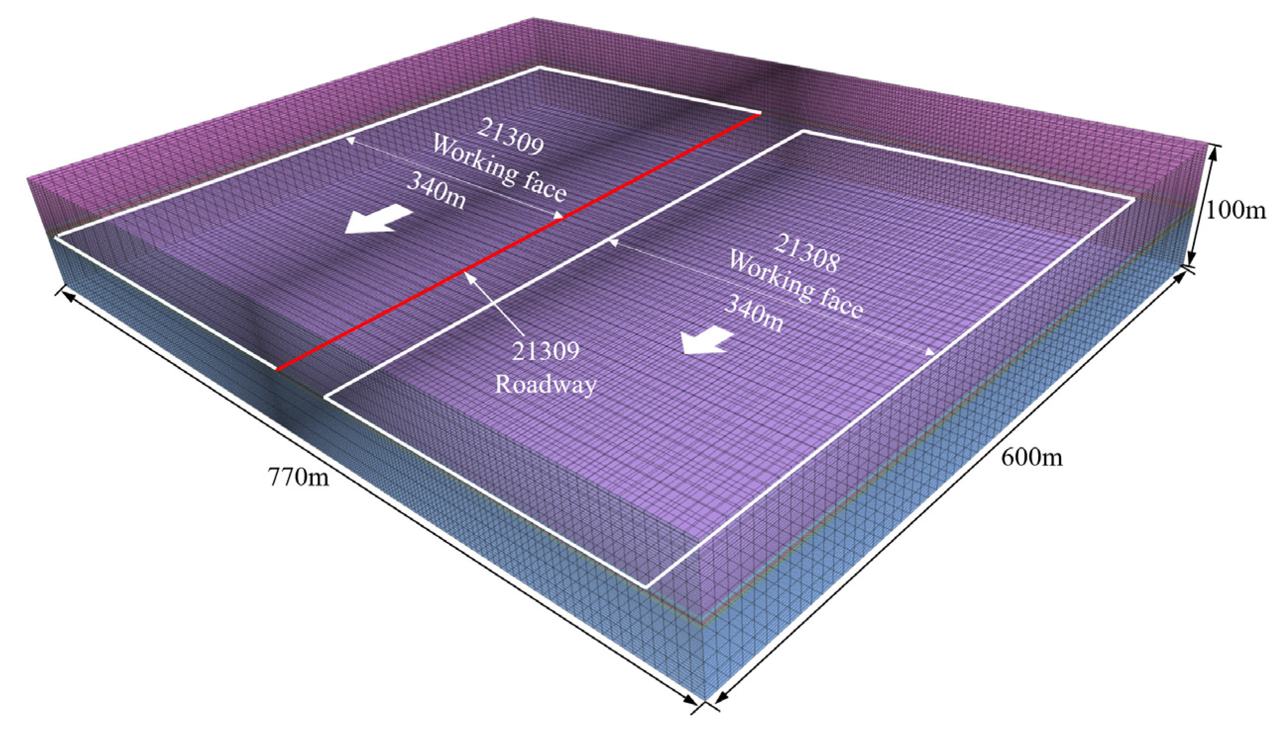
FLAC3D was used to simulate the distribution characteristics of the principal stress and the development of the plastic zone in the 21309 roadway, under the influences of the two mining operations at the 21308 and 21309 working faces. First, a numerical model was established. The dimensions of this model were 770 m along the X-axis, 600 m along the Y-axis, and 100 m along the Z-axis. The model is presented in Figure 7.

Figure 7.
Numerical model.
The Mohr–Coulomb constitutive model was adopted as the failure criterion. The displacement boundary conditions were applied in the horizontal direction and at the bottom of the model, whereas the stress boundary conditions were used at the top of the model. According to the existing in situ stress test data of the mine, the initial vertical stress is 2.11 MPa along the Z-axis, 1.94 Mpa along the X-axis, and 2.11 Mpa along the Y-axis. The rock mechanical parameters of the roof and floor of the coal seam were determined according to laboratory tests. These values are listed in Table 1.
4. Results
4.1. Distribution Law of Principal Stress
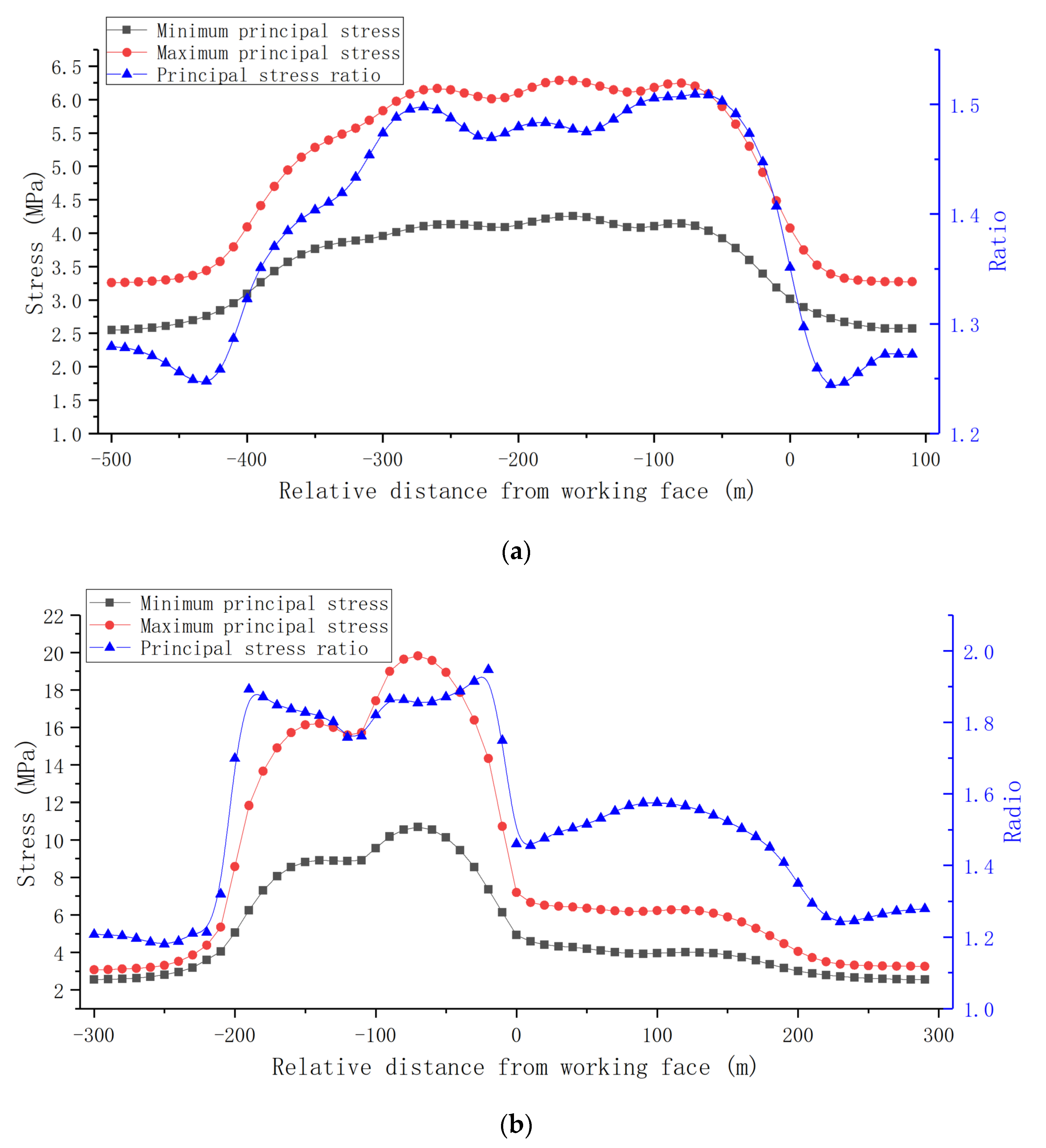
The value and ratio of the maximum principal stress and the minimum principal stress have an important influence on the stability of the surrounding rock of roadways. The maximum principal stress and the minimum principal stress in the surrounding rock of the 21309 roadway along the Y-axis were determined during mining in the 21308 and 21309 working faces; their distributions and ratios are presented in Figure 8. In this figure, the horizontal axis denotes the relative distance from the working face, and position “0” represents the position of the working face. The left Y-axis represents the principal stress value, and the right Y-axis represents the principal stress ratio.

Figure 8.
Relationship between distribution of principal stress and position of working face: (a) primary mining influence; (b) secondary mining influence.
Based on the modeling results, it can be concluded that, when the 21308 working face is mined, the 21309 roadway is affected by primary mining, and the maximum principal stress of the surrounding rock reaches the maximum value at a distance of 170 m behind the working face, where the maximum principal stress is 6.29 Mpa, the minimum principal stress is 4.24 Mpa, and the ratio is 1.48. The ratio of the maximum principal stress to the minimum principal stress reaches the maximum value of 1.51 at a distance of 70 m behind the working face.
When the 21309 working face is mined, the 21309 roadway is affected by secondary mining, and the maximum principal stress of the surrounding rock reaches the maximum value at a distance of 70 m behind the working face, where the maximum principal stress is 19.82 Mpa, the minimum principal stress is 10.69 Mpa, and the ratio is 1.85. The ratio of the maximum principal stress to the minimum principal stress reaches the maximum value of 1.95 at a distance of 20 m behind the working face.
It is evident that the values of the principal stress and the ratio of the maximum principal stress to the minimum principal stress are low when the roadway is affected by primary mining. By contrast, when the roadway is affected by secondary mining, the values of the principal stress and the ratio of the maximum principal stress to the minimum principal stress are considerably higher. In front of the working face, the maximum principal stress initially decreased and then increased, although this change is not evident. The ratio of the maximum principal stress to the minimum principal stress increases with the distance from the working face and reaches a peak value of 1.58 at a distance of 120 m in front of the working face, following which it decreases gradually.
4.2. Developmental Characteristics of the Plastic Zone
According to the Kastner Formula (1), the radius of the plastic zone in the roadway surrounding rock is 1.91 m. According to Equation (2), the plastic zone depth of the surrounding rock is approximately 1.62 m, which has a weak relationship with the polar coordinates of the surrounding rock. The plastic zone of the surrounding rock, calculated using the formula, is large. Owing to the different simplification degrees of the stress fields in the roadway, the calculation results differ significantly. Therefore, further research is necessary.
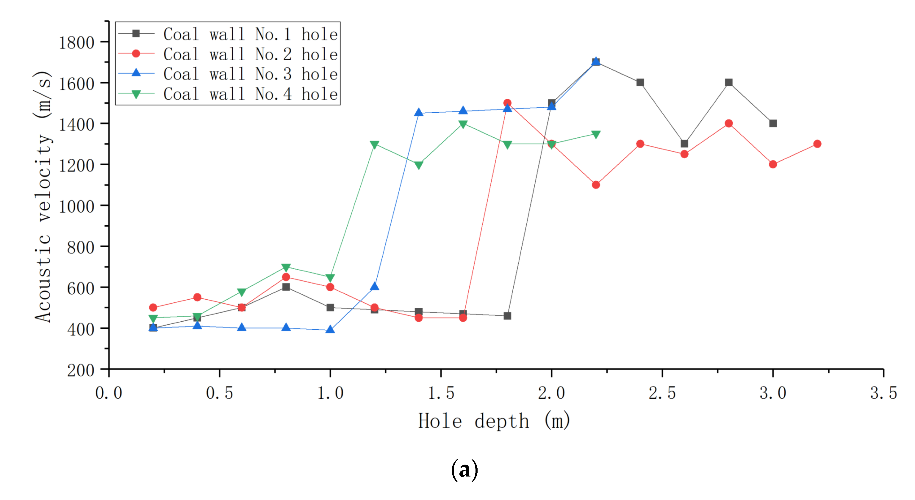
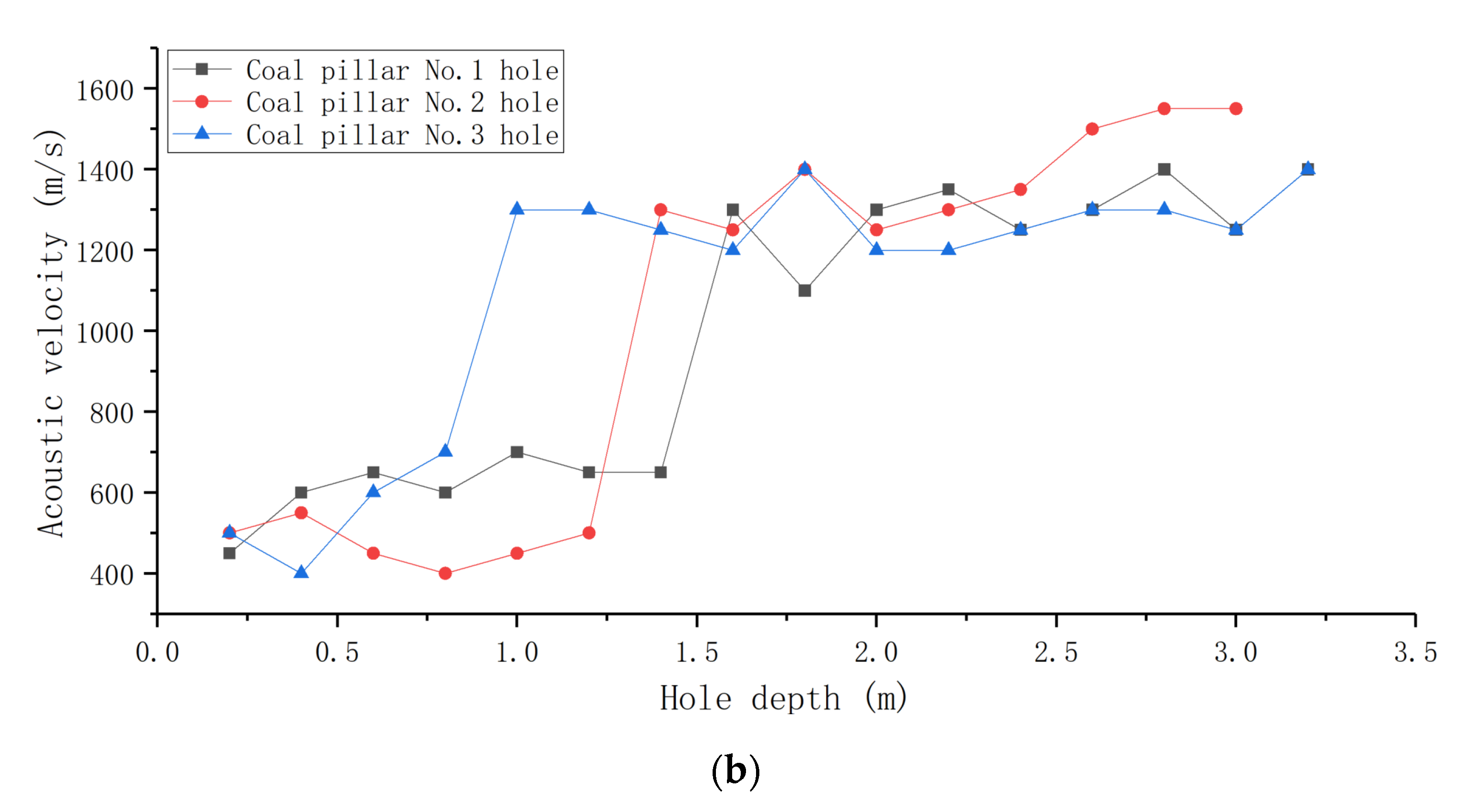
The results of the broken rock zone detection are shown in Figure 9. As shown in Figure 9a, the acoustic propagation velocities at the four test holes on the coal wall side remain essentially unchanged in the plastic zone with a low hole depth; furthermore, the wave velocity is low. As the distance from the hole opening exceeds 1.8, 1.6, 1.2, and 1.0 m, the wave velocity increases sharply, indicating that the coal wall enters the elastic zone. Therefore, it is concluded that the broken rock zone ranges for the four measuring holes on the coal wall are 1.8, 1.6, 1.2, and 1.0 m. Similarly, as shown in Figure 9b, the broken rock zone ranges for the three measuring holes on the coal pillar side are 1.4, 1.2, and 0.8 m.
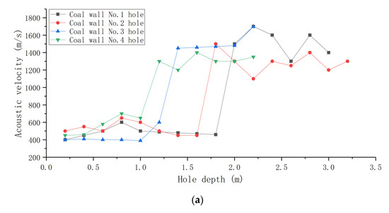
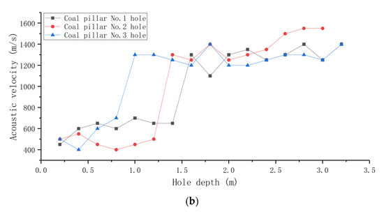
Figure 9.
Acoustic propagation velocity of surrounding rock: (a) coal wall side hole; (b) coal pillar side hole.
The statistics of the broken rock zone detection results are presented in Table 2. Based on the test results, it is evident that, the shorter the distance is from the working face, the greater is the range of the broken rock zone. From 45 m to 15 m in front of the working face, the broken rock zone of the coal pillar side increases from 0.8 m to 1.4 m, while the broken rock zone of the coal wall side increases from 1.0 m to 1.8 m. The range of the broken rock zone of the coal wall is larger than that of the coal pillar.
Table 2.
Statistics of broken zone test results.
The plastic zone range, calculated by the formula, is 1.91 m and 1.62 m, and the maximum plastic zone range, obtained via field observations, is 1.8 m; these values are highly similar. It can be considered that the range obtained using the calculation formula is the plastic zone range of the surrounding rock with the most significant damage. Thus, it is safe to design the support according to the maximum plastic zone of the surrounding rock; this, however, is not necessary. This will waste materials and equipment, resulting in high support costs. Therefore, it is essential to obtain the range of the plastic zone and also further study its distribution characteristics.
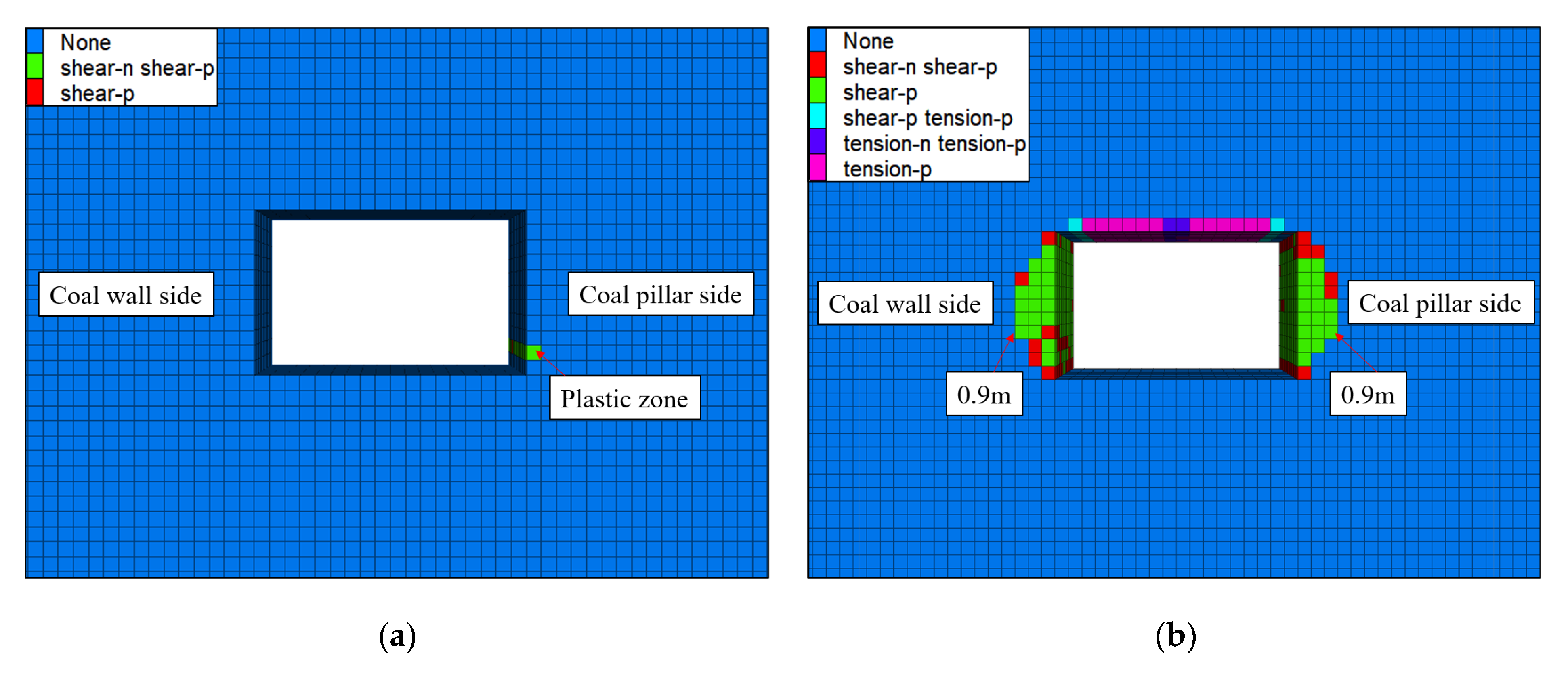
To better understand the distribution characteristics of the plastic zone, two small FLAC3D numerical models of the 21309 roadway under the two mining influences were established. The dimensions of the numerical model were 70 m along the X-axis, 3 m along the Y-axis, and 40 m along the Z-axis. The Mohr–Coulomb constitutive model was adopted as the failure criterion. The displacement boundary conditions were used in the Y-axis direction, whereas the stress boundary conditions were used in the other directions.
The stress determined from the large numerical model was applied to the small model. The required stress value was selected from the location where the ratio of the maximum principal stress to the minimum principal stress was the largest; a distance of 70 m behind the working face was selected for primary mining. The initial stresses applied to the small numerical model were σx = −5.32 MPa, σy = −4.32 MPa, σz = −5.25 MPa, and τxz = −9.95 MPa.
During secondary mining, the roadway behind the working face collapses but the ratio of the maximum principal stress to the minimum principal stress 20 m behind the working face is considerably greater than that in front of the working face. This location is close to the working face; therefore, it is still considered as the research object. The initial stresses applied to the small numerical model were σx = −8.00 MPa, σy = −8.21 MPa, σz = −14.00 MPa, and τxz = 0.25 MPa. The modeling results are presented in Figure 10.
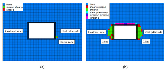
Figure 10.
Development of plastic zone in surrounding rock: (a) primary mining influence; (b) secondary mining influence.
It is evident from the modeling results that, when the roadway is affected by primary mining, the development of the plastic zone in the surrounding rock is significantly limited. The surrounding rocks of the roof and floor are relatively complete, and only a small range of the plastic zone appears in the bottom corner of the coal pillar side. By contrast, the plastic zone in the surrounding rock is large when the roadway is affected by secondary mining. The plastic zone of the roof is small, the maximum depth is 0.3 m, the developmental range of the two sides is large, the maximum damage depth is 0.9 m, and the floor is relatively intact.
The range of the plastic zone obtained via numerical modeling is significantly smaller than that obtained using the above analyses. This is likely because the joints and structures in the rock mass were not considered in the numerical modeling, and the mechanical parameters of the rock were used instead of the rock mass.
4.3. Optimization of Roadway Support Design
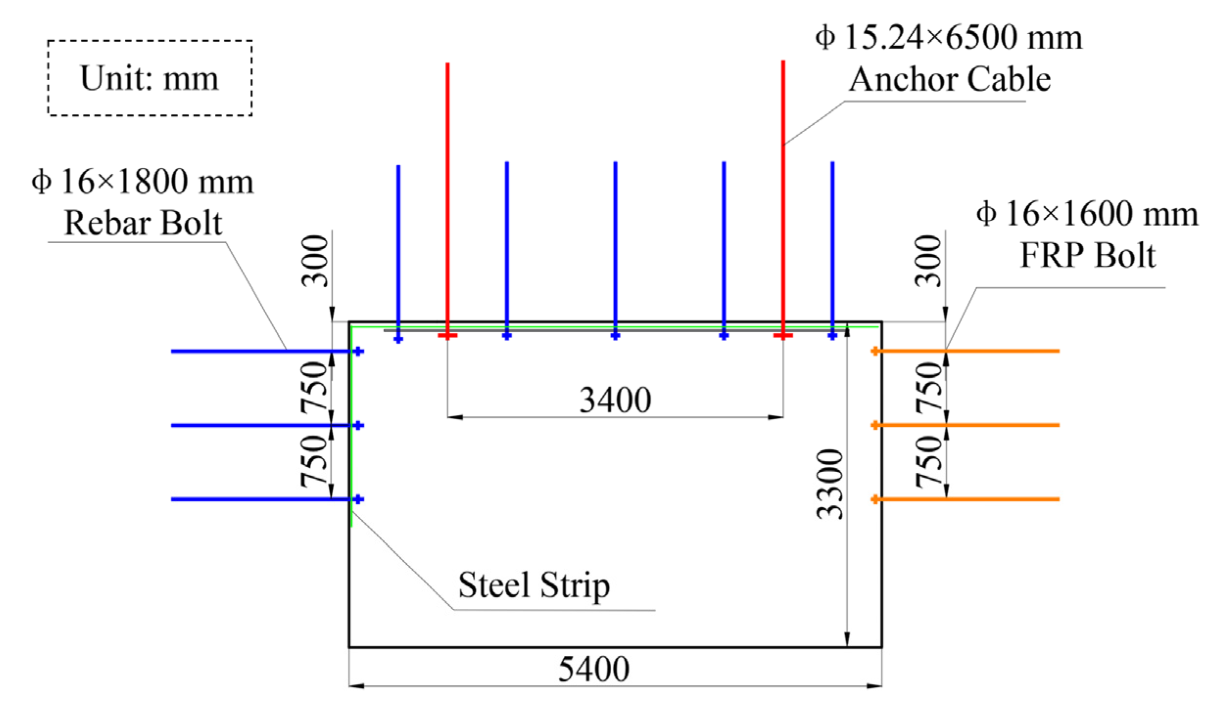
According to the results of the aforementioned analyses, the support design is optimized. As the plastic zone at the side of the roadway is large, bolt support should be employed to prevent damage to the surrounding rock. The maximum range of the plastic zone obtained from the research results is 1.9 m. To prevent roof caving accidents caused by bolt support failures, two anchor cables were added to the roof. This optimized support design is illustrated in Figure 11.
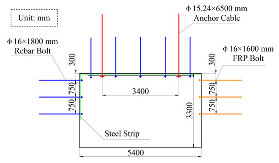
Figure 11.
Optimized support design.
Each row of the roadway roof was supplemented with two anchor cables with a diameter of 15.24 mm, length of 6500 mm, spacing of 3400 mm, and row spacing of 2400 mm. The coal pillar side was supported with a rebar bolt and a steel strip. Each row included three bolts, with a diameter of 16 mm, length of 1800 mm, spacing of 750 mm, and row spacing of 1200 mm. Fiber-reinforced plastic bolts with a length of 1600 mm were used for the coal wall side; except for the length, the other support design was identical to those for the coal pillar side.
To monitor the deformation in the surrounding rock of the roadway after the optimization of the support design, a deep basis point separation monitor was installed at the roof, coal wall side, and coal pillar side of the 21309 roadway. The monitoring results are presented in Figure 12.
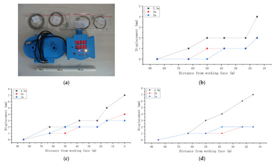
Figure 12.
Surrounding rock deformation: (a) field-monitoring instrument; (b) deformation trend of roof; (c) deformation trend of coal wall side; (d) deformation trend of coal pillar side.
Based on the monitoring results, it can be concluded that, with the advancement of the working face, the displacement at each basis point increases gradually. The maximum displacements of the three basis points at 5.5, 3, and 2 m of the roof are 4, 2, and 2 mm, respectively. The maximum displacements of basis points at 4.5, 2, and 1 m of the coal wall side are 7, 4, and 3 mm, respectively. Furthermore, the maximum displacements of the three basis points at 4.5, 2, and 1 m of the coal pillar side are 7, 2, and 2 mm, respectively. The change in the displacement at each basis point of the roof and the two sides was relatively small; this indicates that, after the optimized support design was adopted for the 21309 roadway, there was no clear separation and deformation in the surrounding rock.
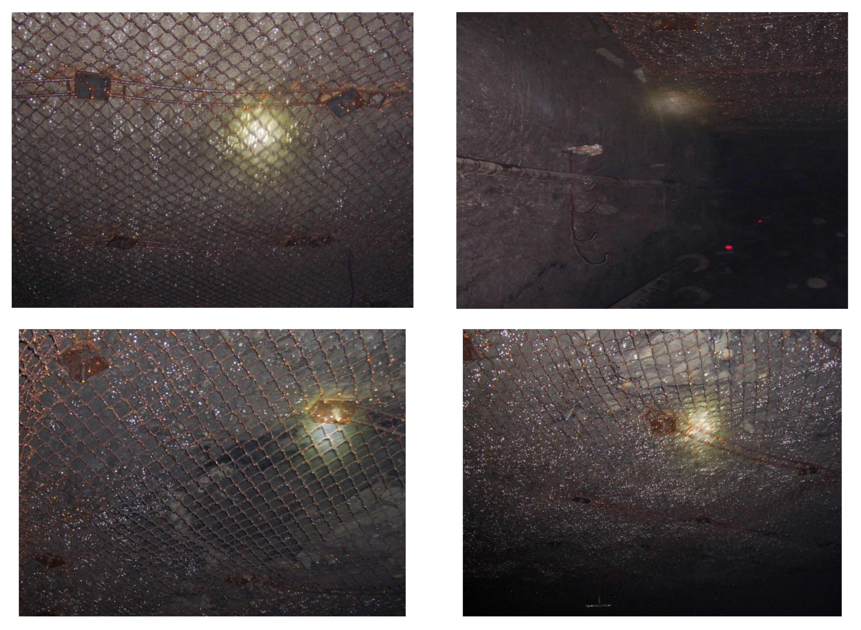
The field applications are illustrated in Figure 13. It can be seen that the maintenance effect of the roadway is good, the surrounding rock is complete, and there is no apparent deformation. This indicates that the roadway support has not failed and that the optimized support design meets the requirements of field application.
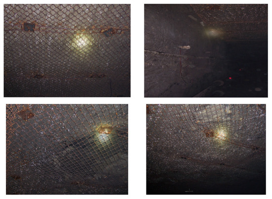
Figure 13.
Field application of optimized support design.
5. Discussion
In this study, three different research methods were used to analyze the failure state of the roadway surrounding rock under the influence of mining, and an effective support design was proposed. The following section will compare three different research methods to analyze their advantages, disadvantages, and applicability.
Subsequently, the Mohr–Coulomb theory was used to discuss the entire process of the “original–failure–stability” conditions of the roadway surrounding rock. In addition, a special phenomenon was also observed during the field observations. The failure range of the roadway surrounding rock on the coal wall side was greater than that on the coal pillar side. This phenomenon is discussed in the following section.
5.1. Different Research Methods and Results
In this paper, three common research methods were used to analyze the distribution characteristics of the plastic zone of roadway—namely, theoretical calculations, field observations, and numerical modeling.
The operation process of theoretical calculation is convenient, and the results can be obtained quickly when the parameters are known. However, the general theoretical analysis can only obtain the developmental range of the plastic zone, and it is difficult to obtain the specific developmental characteristics of the plastic zone. Using theoretical calculation to guide the support design will make the design not targeted, it is very likely to cause support failure or waste of support materials. Results obtained by the field observations should have the highest accuracy. However, the workload of field observations is large, and the observer’s labor intensity is high. This method is usually inconvenient and has great limitations in the selection of measurement location. Numerical modeling can well show the distribution of plastic zone of roadway surrounding rock, and the operation is convenient. The targeted support can be designed according to the research results. However, because the numerical model will simplify the rock mass so that the accuracy of the results is not high.
Therefore, different research methods have different advantages and applicability in studying the failure of roadway surrounding rock. Combining different research methods can achieve more comprehensive and complete research results.
5.2. Excavation Compensation Effect
Mining can cause stress concentration in the roadway surrounding rock, deformation, and damage in the surrounding rock, and roadway accidents. This situation is more evident under the influence of secondary mining. According to the numerical modeling results, under the influence of secondary mining, the maximum principal stress can reach 10 times the original rock stress.
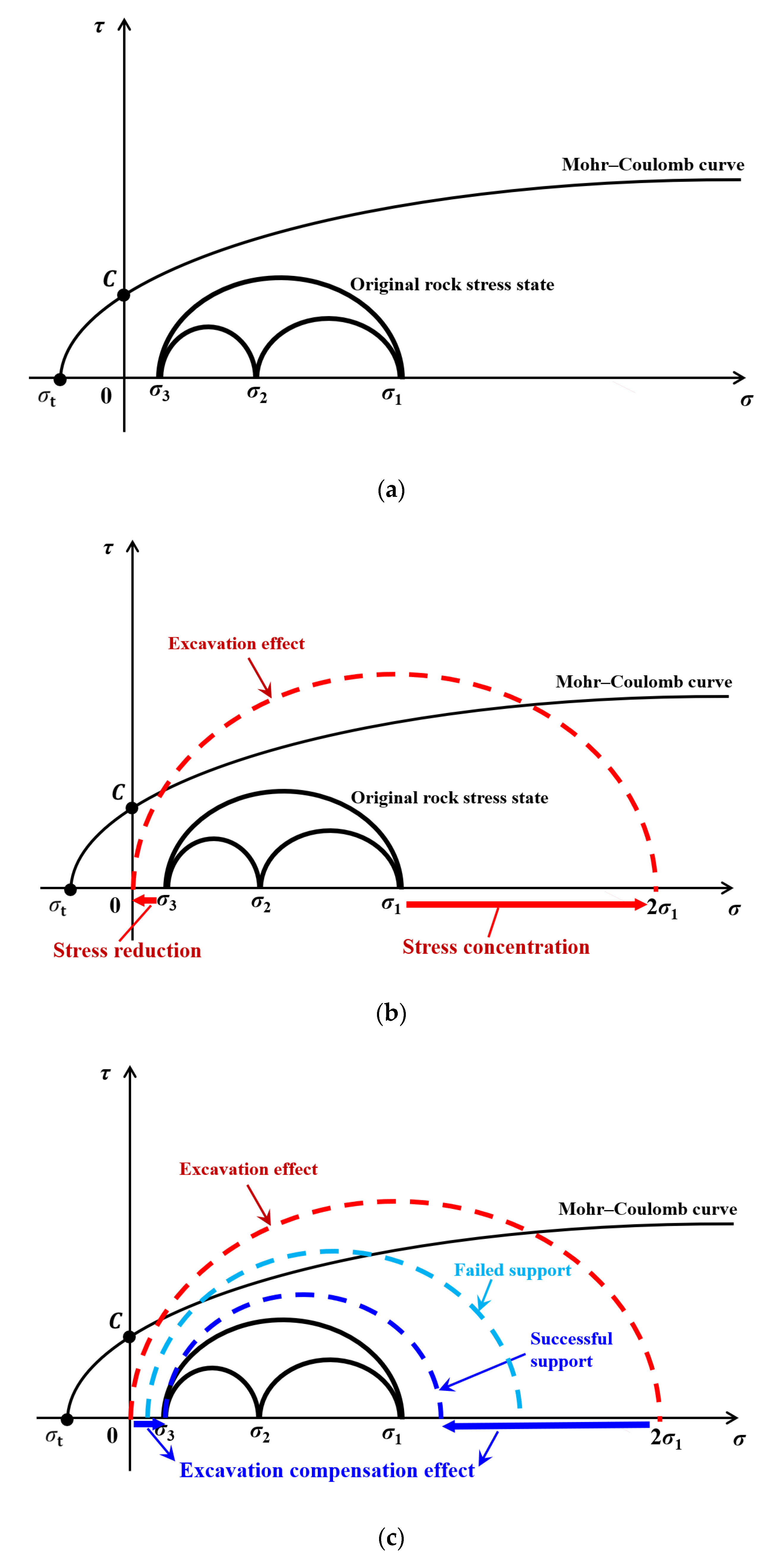
According to the Mohr–Coulomb theory, the failure of a rock mass is mainly determined by its maximum principal stress (σ1) and minimum principal stress (σ3), as shown in Figure 14a. In this case, the rock surrounding the roadway is in the original rock stress state. When mining activities are conducted, the original rock stress state of the surrounding rock is disrupted. The stress concentration caused by the “excavation effect” is the fundamental cause of surrounding rock damage; the stress state of the surrounding rock at this time may be as that shown in Figure 14b. Roadway maintenance aims to achieve “excavation compensation effect” to offset the “excavation effect” through certain means, in order to reduce the stress concentration and area of Mohr’s circle of the surrounding rock; in this case, the stress state of surrounding rock may be as that shown in Figure 14c.
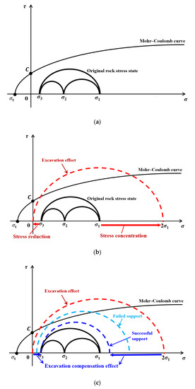
Figure 14.
Mohr–Coulomb theory: (a) original rock stress state; (b) excavation effect; (c) excavation compensation effect.
The most effective method for achieving the “excavation compensation effect” is to reduce the maximum principal stress of the surrounding rock and increase its minimum principal stress. Commonly used methods include roof cutting and pressure relief, roadway support technology, shotcrete and grouting, and excavation space filling. In this study, the considered study site had low in situ stress and a simple geological structure. Conventional surrounding rock control methods can meet the requirements of safety. For some roadways with largely buried depths, high stresses, complex structures, or soft rocks, more complex means are needed to achieve the “excavation compensation effect”. However, this is a challenge that needs to be addressed through future research in the field of underground engineering.
5.3. Roof Cutting and Pressure Relief
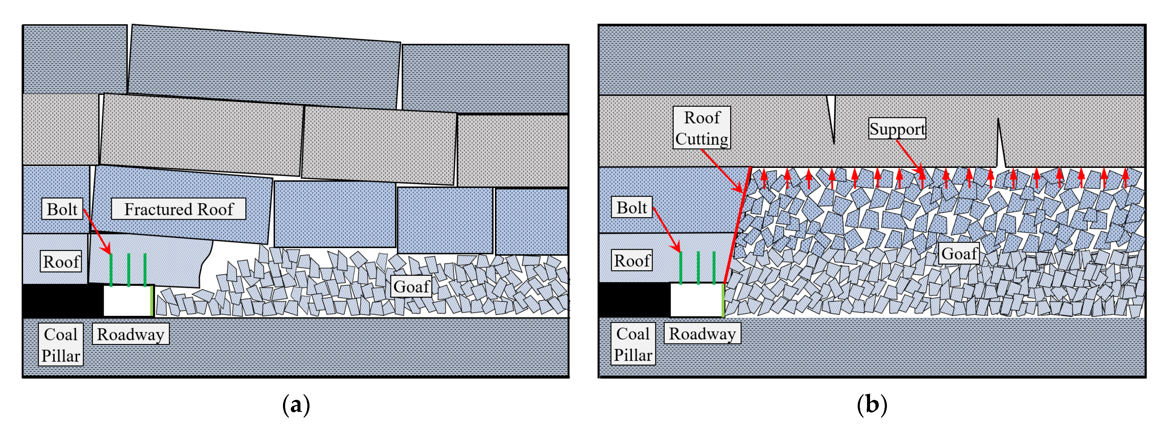
Based on the broken rock zone detection for the surrounding rock, it can be concluded that the rock failure range on the coal wall side is greater than that on the coal pillar side. This is likely due to the fracture of the roof in the goaf behind the working face, whereby the pressure is transmitted to the two sides along the roof, as shown in Figure 15a. As the coal wall side is closer to the goaf, the transmitted stress is greater, and the damage is more severe. The coal pillar side is also damaged owing to the pressure exerted by the roof, which is clearly significantly dangerous. To reduce the damage to the roadway surrounding rock, the stress transmission path from the goaf to the roadway needs to be separated; one effective technology currently available is roof cutting and pressure relief, as shown in Figure 15b.
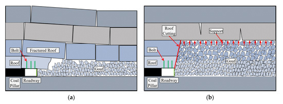
Figure 15.
Rock strata fracture diagram: (a) traditional mining method; (b) roof cutting and pressure relief.
If the roof cutting approach is successful, the stress transmission path of the roof will be completely cut off, which is highly beneficial for the maintenance of the roadway surrounding rock. After roof cutting, assuming that all the rocks fall within the roof cutting range in the goaf, the gangue will serve as effective support for the roof rock stratum owing to the expansion of the rock, as shown in Figure 15b. This considerably alleviates roof rock fracture, significantly reduces mine pressure concentration, and fundamentally inhibits the occurrence of mine disasters. This is essentially similar to the 110 and N00 mining methods proposed by Professor He Manchao [27,28,29,30,31,32].
6. Conclusions
This paper presented a comprehensive case study of the surrounding rock failure characteristics and the control techniques for the 21309 roadway at the Huojitu coal mine through three research methods: theoretical calculations, field observations, and numerical modeling. The main conclusions of this study are as follows:
- 1.
- The shorter the distance is from the working face, the larger is the developmental range of the broken rock zone; the range of the broken rock zone of the coal wall side is larger than that of the coal pillar side. Through formula calculation and field observation, the maximum damage range in surrounding rock on both sides of the roadway can reach 1.8 m.
- 2.
- Under the influence of primary mining, the maximum principal stress of the roadway surrounding rock reaches the maximum value of 6.29 MPa at a distance of 170 m behind the working face. The ratio of the maximum principal stress to the minimum principal stress reaches the maximum value of 1.51 at a distance of 70 m behind the working face. Moreover, the plastic zone of the surrounding rock is less developed, and the surrounding rocks of the roof and floor are relatively complete.
- 3.
- Under the influence of secondary mining, the maximum principal stress of the roadway surrounding rock reaches the maximum value of 19.82 MPa at a distance of 70 m behind the working face. The ratio of the maximum principal stress to the minimum principal stress reaches the maximum value of 1.95 at a distance of 20 m behind the working face. The plastic zone of the surrounding rock is large, the plastic zone of the roof is small, the maximum depth is 0.3 m, the developmental ranges of the two sides are large, the maximum damage depth is 0.9 m, and the floor is relatively intact.
- 4.
- This study demonstrates that a combination of multiple research methods is needed for further comprehensive studies to avoid partial conclusions. The methods and results presented herein are expected to serve as a reference for the analysis of roadway surrounding rock states under similar conditions; optimized support design is also expected to guide field applications.
Author Contributions
Conceptualization, X.Y. and G.Y.; methodology, G.Y., R.H. and Y.W.; software, G.Y.; validation, R.H., Y.W. and J.L.; formal analysis, R.H. and J.L.; investigation, J.Z. and S.H.; resources, X.Y. and Y.W.; data curation, J.Z. and S.H.; writing—original draft preparation, G.Y.; writing—review and editing, R.H., Y.W. and J.L.; visualization, G.Y. and Y.W.; supervision, X.Y.; project administration, G.Y.; funding acquisition, X.Y. All authors have read and agreed to the published version of the manuscript.
Funding
This work was funded by the National Natural Science Foundation of China, Grant No. 52074295, and the Fundamental Research Funds for the Central Universities, Grant No. 2021YJSSB13.
Acknowledgments
The authors appreciate the support of the School of Energy and Mining Engineering, China University of Mining and Technology-Beijing, and Huojitu coal mine of China Shenhua Shendong Coal Group Corporation Limited for field practice study.
Conflicts of Interest
The authors declare no conflict of interest.
References
- Basarir, H.; Sun, Y.; Li, G. Gateway stability analysis by global-local modeling approach. Int. J. Rock Mech. Min. Sci. 2019, 113, 31–40. [Google Scholar] [CrossRef]
- Kang, H.; Wu, L.; Gao, F.; Lv, H.; Li, J. Field study on the load transfer mechanics associated with longwall coal retreat mining. Int. J. Rock Mech. Min. Sci. 2019, 124, 104141. [Google Scholar] [CrossRef]
- Shabanimashcool, M.; Li, C. Vertical stress changes in multi-seam mining under supercritical longwall panels. Int. J. Rock Mech. Min. 2013, 106, 39–47. [Google Scholar]
- Feng, G.; Wang, P.; Chugh, Y.; Zhao, J.; Wang, Z.; Zhang, Z. A Coal Burst Mitigation Strategy for Tailgate during Deep Mining of Inclined Longwall Top Coal Caving Panels at Huafeng Coal Mine. Shock Vib. 2018, 2018, 5929785. [Google Scholar] [CrossRef]
- Paul, A.; Singh, A.; Loui, P.; Singh, A.; Khandelwal, M. Validation of RMR-based support design using roof bolts by numerical modeling for underground coal mine of Monnet Ispat, Raigarh, India—a case study. Arab. J. Geosci. 2012, 5, 1435–1448. [Google Scholar] [CrossRef]
- Sun, X.; Zhao, C.; Tao, Z.; Kang, H.; He, M. Failure mechanism and control technology of large deformation for Muzhailing Tunnel in stratified rock masses. Bull. Eng. Geol. Environ. 2021, 80, 4731–4750. [Google Scholar] [CrossRef]
- Kang, H.; Lin, J.; Fan, M. Investigation on support pattern of a coal mine roadway within soft rocks—A case study. Int. J. Coal Geol. 2015, 140, 31–40. [Google Scholar] [CrossRef]
- Yang, S.; Chen, M.; Jing, H.; Chen, K.; Meng, B. A case study on large deformation failure mechanism of deep soft rock roadway in Xin’An coal mine, China. Eng. Geol. 2017, 217, 89–101. [Google Scholar] [CrossRef]
- Majcherczyk, T.; Niedbalski, Z.; Małkowski, P.; Bednarek, Ł. Analysis of yielding steel arch support with rock bolts in mine roadways stability aspect. Arch. Min. Sci. 2014, 59, 641–654. [Google Scholar] [CrossRef] [Green Version]
- Mahdevari, S.; Shahriar, K.; Sharifzadeh, M.; Tannant, D. Stability prediction of gate roadways in longwall mining using artificial neural networks. Neural Comput. Appl. 2017, 28, 3537–3555. [Google Scholar] [CrossRef]
- Shen, B.; King, A.; Guo, H. Displacement, stress and seismicity in roadway roofs during mining-induced failure. Int. J. Rock Mech. Min. Sci. 2008, 45, 672–688. [Google Scholar] [CrossRef]
- Zhang, G.; Liang, S.; Tan, Y.; Xie, F.; Chen, S.; Jia, H. Numerical modelling for longwall pillar design: A case study from a typical longwall panel in China. J. Geophys. Eng. 2018, 15, 121–134. [Google Scholar] [CrossRef]
- Lawrence, W. A method for the design of longwall gateroad roof support. Int. J. Rock Mech. Min. 2009, 46, 789–795. [Google Scholar] [CrossRef]
- Jiang, Y.; Yoneda, H.; Tanabashi, Y. Theoretical estimation of loosening pressure on tunnels in soft rocks. Tunn. Undergr. Space Technol. 2001, 16, 99–105. [Google Scholar] [CrossRef]
- Leitman, M.; Villaggio, P. Plastic zone around circular holes. J. Eng. Mech. 2009, 135, 1467–1471. [Google Scholar] [CrossRef]
- Sun, Y.; Li, G.; Zhang, N.; Chang, Q.; Xu, J.; Zhang, J. Development of ensemble learning models to evaluate the strength of coal-grout materials. Int. J. Min. Sci. Technol. 2021, 31, 153–162. [Google Scholar] [CrossRef]
- Jiang, L.; Kong, P.; Shu, J.; Fan, K. Numerical Analysis of Support Designs Based on a Case Study of a Longwall Entry. Rock Mech. Rock Eng. 2019, 52, 3373–3384. [Google Scholar] [CrossRef]
- Liu, C.; Yue, S.; Wang, M.; Li, J.; Deng, S.; Zhang, G.; Ji, Y.; Li, Z.; Xu, T. Loading Device of Explosive Stress Wave in High Confining Pressure and Dynamic Response of Composite Structure. Compos. Struct. 2021, 258, 113198. [Google Scholar] [CrossRef]
- Liu, H.; Guo, L.; Cao, G.; Zhao, X.; Wang, P.; Huo, T.; Yang, G.; Hao, C.; Wang, Q. Comprehensive Study of Strata Movement Behavior in Mining a Longwall Top Coal Caving Panel of a Composite Coal Seam with Partings. Appl. Sci. 2020, 10, 5311. [Google Scholar] [CrossRef]
- Malkowski, P.; Ostrowski, L.; Bachanek, P. Modelling the small throw fault effect on the stability of a mining roadway and its verification by in situ investigation. Energies 2017, 12, 2082. [Google Scholar]
- Liu, H.; Qiao, B.; Ma, N. Stability analysis and design of roadways in adjacent seams: A case study from Tashan coal mine in China. Arab. J. Geosci. 2020, 13, 308. [Google Scholar] [CrossRef]
- Liu, H.; Guo, L.; Zhao, X.; Wang, P. Effect of Principal Stress Field on the Development of Plastic Zone ahead of the Gateroad. Energies 2020, 13, 4356. [Google Scholar] [CrossRef]
- Li, C.; Guo, X.; Lian, X.; Ma, N. Failure Analysis of a Pre-Excavation Double Equipment Withdrawal Channel and Its Control Techniques. Energies 2020, 13, 6368. [Google Scholar] [CrossRef]
- Gao, F.; Stead, D.; Kang, H. Numerical Simulation of Squeezing Failure in a Coal Mine Roadway due to Mining-Induced Stresses. Rock Mech. Rock Eng. 2015, 48, 1635–1645. [Google Scholar] [CrossRef]
- Ma, N.; Li, J.; Zhao, Z. Distribution of the deviatoric stress field and plastic zone in circular roadway surrounding rock. J. China Univ. Min. Technol. 2015, 44, 209–213. [Google Scholar]
- Guo, X.; Zhao, Z.; Gao, X.; Wu, X.; Ma, N. Analytical solutions for characteristic radii of circular roadway surrounding rock plastic zone and their application. Int. J. Min. Sci. Technol. 2019, 29, 263–272. [Google Scholar] [CrossRef]
- He, M.; Gao, Y.; Yang, J.; Gong, W. An Innovative Approach for Gob-Side Entry Retaining in Thick Coal Seam Longwall Mining. Energies 2017, 10, 1785. [Google Scholar] [CrossRef] [Green Version]
- He, M.; Wang, Q.; Wu, Q. Innovation and future of mining rock mechanics. J. Rock Mech. Geotech. Eng. 2021, 13, 1–21. [Google Scholar] [CrossRef]
- Wang, Y.; Gao, Y.; Wang, E.; He, M.; Yang, J. Roof Deformation Characteristics and Preventive Techniques Using a Novel Non-Pillar Mining Method of Gob-Side Entry Retaining by Roof Cutting. Energies 2018, 11, 627. [Google Scholar] [CrossRef]
- Yang, X.; Huang, R.; Yang, G.; Wang, Y.; Cao, J.; Liu, J.; He, M. Validation study of no-pillar mining method without advance tunneling: A case study of a mine in China. Energy Sci. Eng. 2021, 9, 1761–1772. [Google Scholar] [CrossRef]
- Yang, X.; Liu, C.; Sun, H.; Yue, S.; Ji, Y.; Zhang, X.; Hou, L. Research on the Deformation Mechanism and Directional Blasting Roof Cutting Control Measures of a Deep Buried High-Stress Roadway. Shock. Vib. 2020, 2020, 6742504. [Google Scholar] [CrossRef]
- Liu, J.; He, M.; Hou, S.; Zhu, Z.; Wang, Y.; Yang, J. Force change of the gravel side support during gangue heaping under a new non-pillar-mining approach. Geomech Eng. 2021, 27, 31–43. [Google Scholar]


Publisher’s Note: MDPI stays neutral with regard to jurisdictional claims in published maps and institutional affiliations. |
© 2021 by the authors. Licensee MDPI, Basel, Switzerland. This article is an open access article distributed under the terms and conditions of the Creative Commons Attribution (CC BY) license (https://creativecommons.org/licenses/by/4.0/).