1. Introduction
Over several decades, a large primary and secondary network of pavement roads and highways has been introduced by all developed countries to connect urban centres, metropolis and industrial areas with each other. This connectivity, combined with marine and air modes of transport, has generated a great socioeconomic impact derived from the transport of goods and passengers [
1].
However, there are many rural areas, small cities and, especially, developing countries where it is not always possible to build this great network of roads due to economic, accessibility or constructability issues, as well as the fact that other modes of transport have a lower level of development and, therefore, cannot even be implemented. In this way, rural and low volume roads are a major opportunity to improve the connectivity and socioeconomic development of these areas [
2].
Rural roads have different functions according to the level of development of the country where they are built. In developed countries, rural roads are usually designed to connect towns with low populations and agricultural and livestock areas with a low volume of vehicles. On the contrary, in developed countries, rural roads are designed to meet the socioeconomic needs of the rural population, connecting remote areas to basic health services, education and markets [
3].
These types of road can be composed of a subgrade and a thin asphaltic layer or, most commonly, by compaction of an unpaved unbound granular material [
4] or even compaction of stabilised soils that are found in the location of the road [
5].
However, in most cases, these soils, especially clayey soils, present geotechnical problems, such as a lack of bearing capacity, high plasticity or swelling potential, that prevent their use. In order to improve the properties of soils and increase their range of use in civil engineering applications, soil stabilisation for application in road layers has become widespread in recent years [
6,
7].
Soil stabilisation is defined as the improvement of the shear strength, durability stiffness and reduction of the plasticity and swelling potential of soils achieved by mechanical means or the addition of stabilising products, such as a hydraulic binder, fly and rice husk ash, chemical stabilisation, recycled waste and by-products, etc. [
8].
Among all the stabilising products, stabilisation with binders (commonly lime and cement) have been widely used by numerous authors in recent decades [
9,
10,
11,
12]. Nevertheless, the production of these traditional materials generates a negative environmental impact due to the use of raw material resources and the high CO
2 emissions involved in their production [
13].
For the reason mentioned above, in recent years, several studies that analyse the possible stabilisation of soils with industrial by-products or recycled materials, such as biomass fly and bottom ash [
14,
15,
16,
17], phosphogypsum [
18,
19], steel slag [
20,
21] and magnesia oxides [
22,
23], among many others, have been increased.
In addition, in recent years, an alternative to conventional stabilising products and wastes and by-products has emerged: nanomaterials. Nanomaterials are particles with a typical size of between 1 and 100 nm, with a very high specific surface area, which implies a very high reactivity [
24], achieving soil improvements with very low dosages. Nanomaterials commonly used in soil stabilisation are composed of simple oxides, such as SiO
2, TiO
2 or CaCO
3, or carbon nanotubes [
25,
26].
Although a large number of nanoparticles has been developed, the pozzolanic capacity of Nano-SiO2 and its reactivity with lime and cement to form calcium silicate hydrate (CSH) compounds have led most studies to focus on it [
27,
28,
29,
30,
31].
Kulanthaivel et al. [
27] studied the effect of using synthesised Nano-SiO
2 by a sol–gel process together with cement to stabilise clay soil, concluding that a 7% addition of nano-SiO
2 improves the unconfined compressive strength in a ratio of 5:24 and reduces the permeability in the range of 0.01976 cm/s–0.01198 cm/s of the soil, which is consistent with previous studies [
28].
Ghasabkolaei et al. [
30] and Bahmani et al. [
31] studied soil stabilisation with cements and nanosilane with dosages lower than 1% by weight of Nano-SiO
2, observing an increase in the unconfined compressive strength in all the mixtures with nanoparticulate additives and a high formation rate of calcium silicate hydrate (CSH), which implies an improvement in the soil properties.
The present study shows new structural solutions for rural and low-volume roads based on soil stabilised with organosilanes and small amounts of lime and cement. The design parameters of the new sections, which were obtained through laboratory tests, were tested in a real-scale application to verify the feasibility of using the developed solutions. In addition, a medium-to-short-term performance study of the road sections built was carried out to check their durability.
2. Research Purpose and Experimental Programme
This work is a continuation of the one carried out by Rosales et al. [
32] in which a conventional control section was made according to Spanish specifications [
33], and two alternative experimental sections based on nanomaterials and quicklime were performed in order to reduce the total thickness of the treated layers.
In the present work, three new trial sections are proposed with a hybrid stabilisation process in which nanomaterials and small amounts of quicklime and cement are used to reduce their treated thickness with respect to the control section by 40% and improve the mechanical properties and durability.
To carry out the trial sections in a successful manner, the following phases were followed in the present work:
Phase 1. Conceptualisation and predesign of alternative sections based on the study conducted by Rosales et al. [
32].
Phase 2. Physicochemical characterisation of the materials involved in the work—namely, expansive clayey soil, sandy soil, which is a rejection of the production of crushed gravel, lime, cement and nanomaterials.
Phase 3. Laboratory study to obtain the design parameters of the sections. In this phase, the percentages of soil for the mixtures were defined, as well as the quantities of the binders and organosilanes. The California Bearing Ratio (CBR) index and unconfined compressive strength (UCS) were obtained.
Phase 4. Trial section structural design using Everstress 5.0 software. From the CBR index and simple compressive strength, the elastic modulus of the layers composing the sections were determined. Once the elastic parameters of the materials had been defined, the different section options were evaluated by means of a multilayer elastic analysis in the software.
Phase 5. Construction and survey of the experimental sections. In this phase, the road sections were built, and short- and long-term checks of the bearing capacity of the soil were performed by non-destructive tests, such as plate loading and a falling weight deflectometer (FWD).
3. Phase 1. Section Pre-Design
According to the results obtained by Rosales et al. [
32], three alternative sections composed of two layers were proposed: one of lime stabilised expansive clayed soil (CS) and another upper one of a mixture of CS and sandy soil (SS) stabilised with cement.
In the first pre-design stage, the layer thicknesses and soil proportions were not defined; however, the sections and their construction process were defined in a qualitative manner, as shown in
Figure 1.
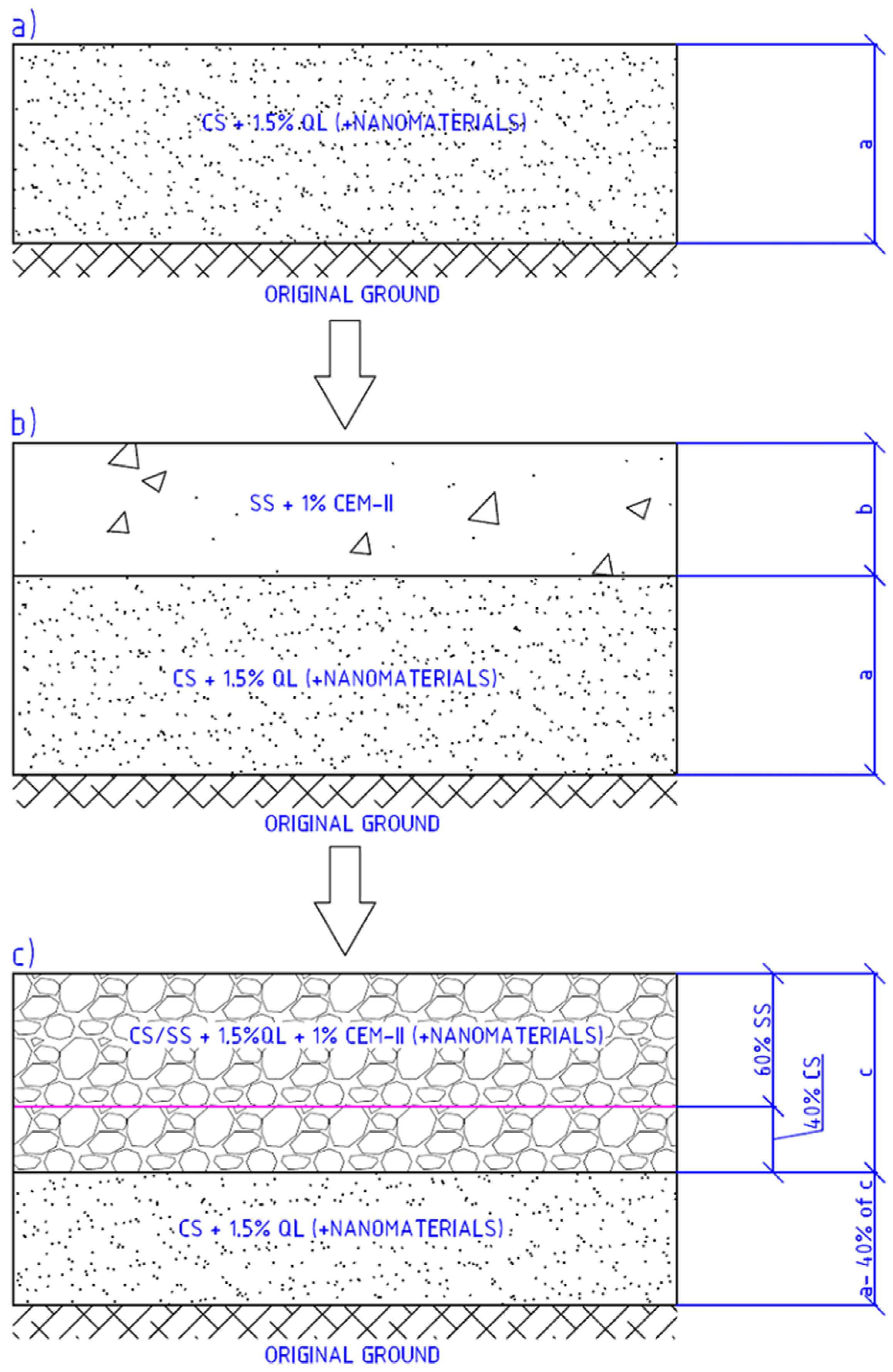
As shown in
Figure 1, the process of construction of the hybrid stabilised sections was carried out in three steps:
Step 1. Spreading, mixing and pre-compaction of the quicklime (or quicklime and nanomaterial) stabilised the clayey soil layer on the original ground. The nanomaterials were added, according to the dosage shown in the following sections, into the mixing water. The curing time of the layer was one day.
Step 2. After one day, the spreading and mixing of the sandy soil layer on top of the compacted quicklime (or quicklime and nanomaterial) stabilised the clayey soil layer and the spreading of the cement.
Step 3. Compaction of the layer composed of a percentage of compacted quicklime (or quicklime and nanomaterial) stabilised clayey soil plus sandy soil and cement. The result is called hybrid stabilised soil.
The following sections analyse the physicochemical properties of the materials involved, as well as the mechanical properties of the mixes to be defined to optimise both the thickness of the mixes and the percentages of the binders.
4. Laboratory Tests
4.1. Phase 2: Materials and Physicochemical Characterisation
In this section, the materials used during the research for the development of the tests and construction of the trial sections are shown.
4.1.1. Soils: Expansive Clayey Soil and Sandy Soil
In this work, two types of soils have been analysed for the subsequent stabilisation and construction of the layers of the trial section: an expansive clayey soil (CS) and a quarry reject from the production of crushed gravel called sandy soil (SS).
The clayey soil (CS) comes from the plot where the real-scale sections are built, in Villacarrillo (Jaén), Andalusia.
The sandy soil comes as a reject from a crushed gravel production quarry located near Villacarrillo. The rejects are subjected to a sieving process to achieve a particle size within the parameters of Spanish regulations [
34].
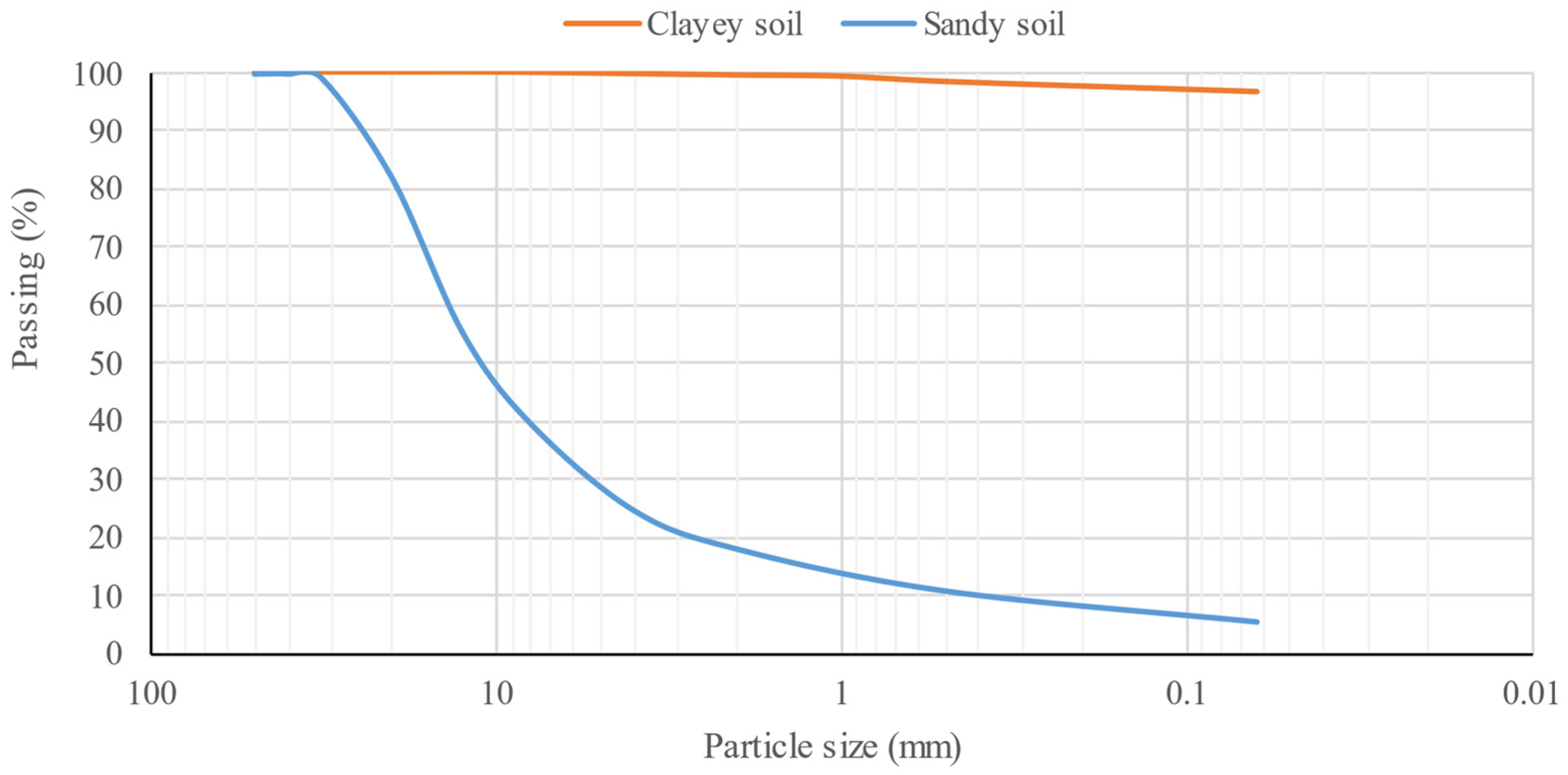
Table 1 shows the physicochemical properties of the two soils analysed, and
Figure 2 shows the granulometric curves of the soils.
As shown in
Table 1, the clayey soil shows a very high plasticity, with a plasticity index greater than 30, a discontinuous granulometry in which 95% of the particles are fine clays and silts and a maximum particle size of 5 mm.
In contrast, the sandy soil has a continuous grain size, composed mainly of particles larger than 4 mm, with a maximum aggregate size of 32 mm and a percentage of fine grains of less than 6%. The plasticity index of SS is 4.2, which indicates that it is not a very plastic material.
Both materials have low percentages of organic matter content and water-soluble sulphates, which make them suitable for use in road layers in accordance with Spanish regulations.
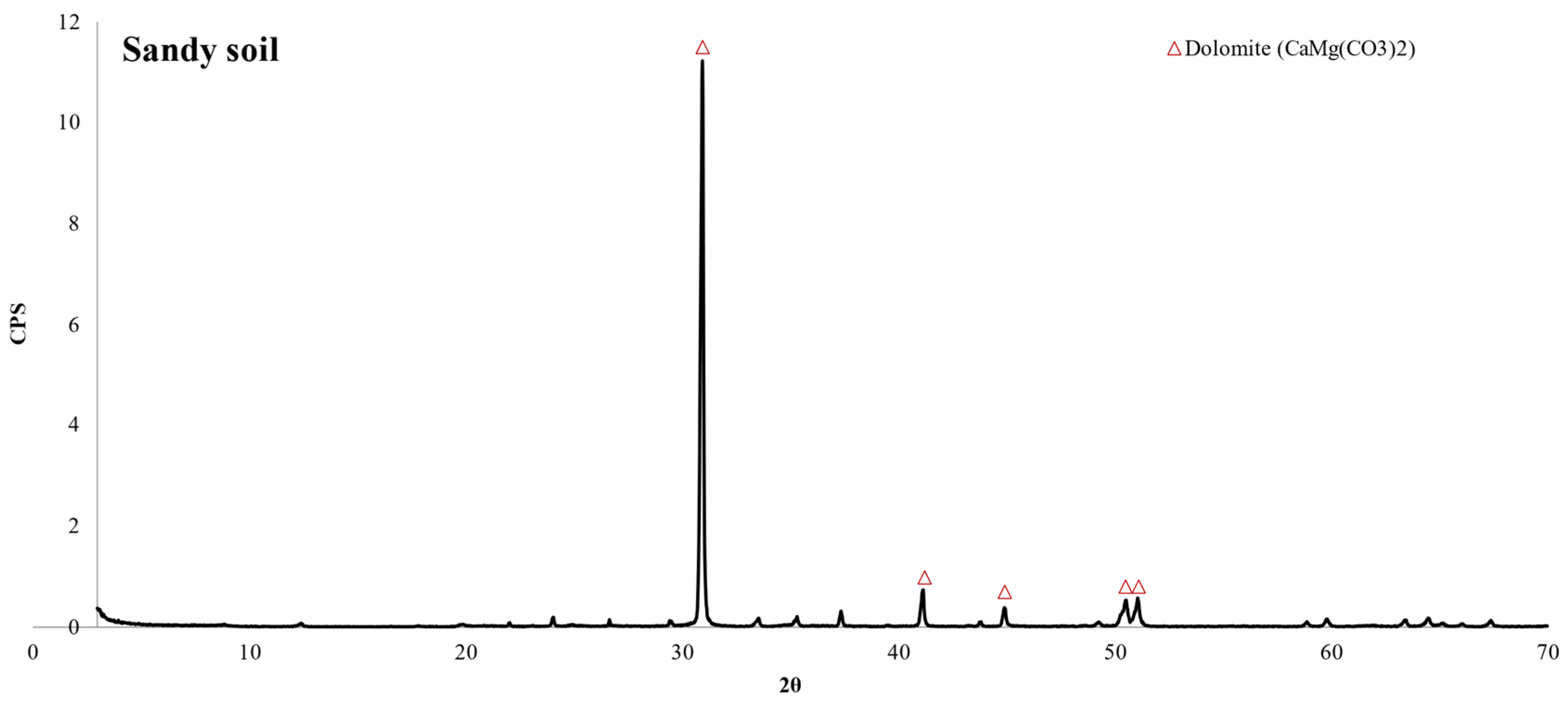
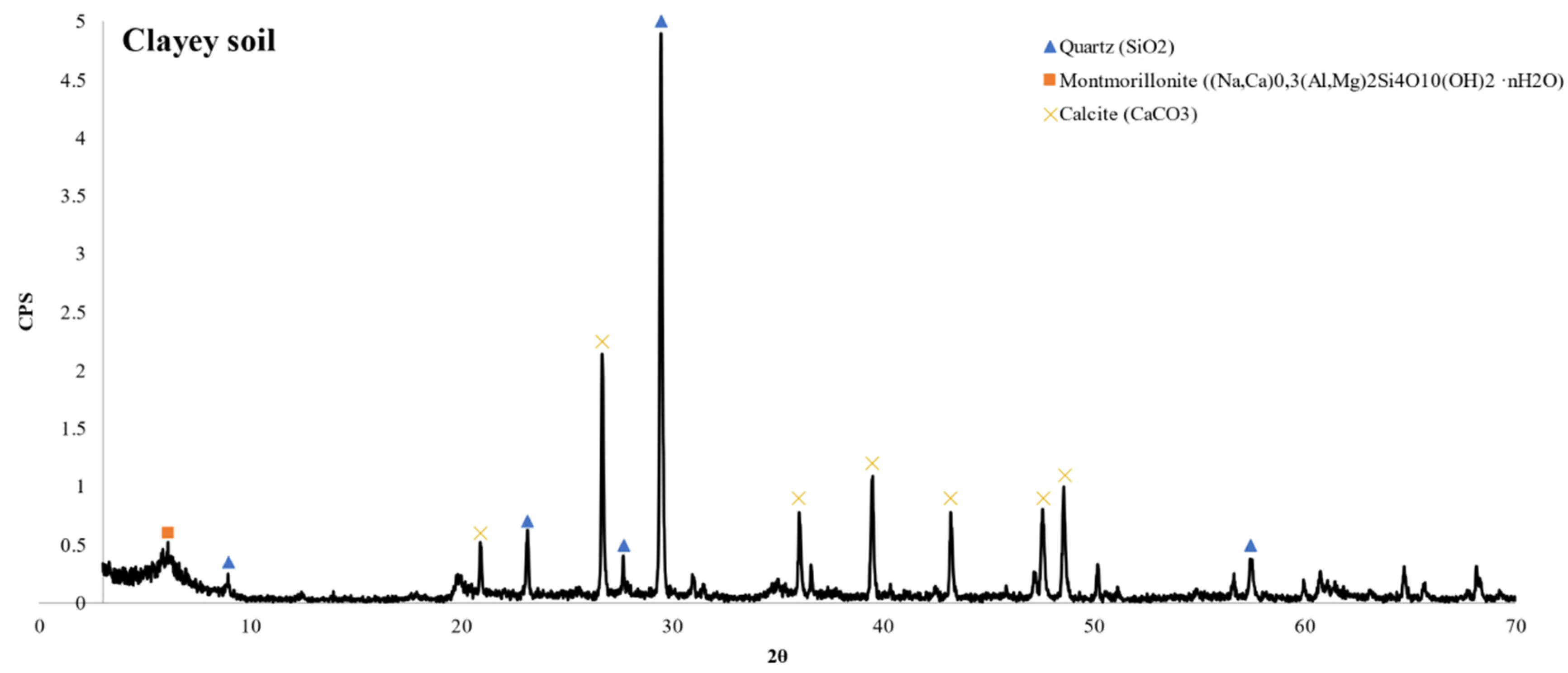
Regarding the composition of the soils, an analysis of the major compounds by X-ray fluorescence (XRF) and mineralogical analysis by X-ray diffraction (XRD) was carried out, as shown in
Table 1 and
Figure 3 and
Figure 4.
The clayey soil presents a main composition of silicon, calcium and aluminium, a typical composition of clays, which is observed in a mineralogy composed of quartz, calcite and montmorrollite-type clay minerals.
The sandy soil has a main composition of calcium and magnesium, a typical composition of dolomite minerals, as shown in the XRD of
Figure 4.
4.1.2. Binders: Quicklime and Cement
Binders are materials that react chemically with water, forming cementitious compounds that can bind and improve the properties of soils, among other functions.
In the present work, two binders have been applied: commercial quicklime (QL)-type CL 90-Q and a commercial ordinary Portland cement (OPC)-type CEM II/B-L 32.5R.
Table 2 shows the composition in the form of oxides of both binders.
4.1.3. Nanomaterials
Three types of silica-based nanomaterials were used in this study, named N1, N2 and N3.
N1 is a concentrated liquid solution of sodium silicate for soil stabilisation, together with binders such as lime or cement. N2 is an organosilane, and N3 is a silica-based acrylic copolymeric in aqueous solution form, intended to be used together in a 1:1 ratio.
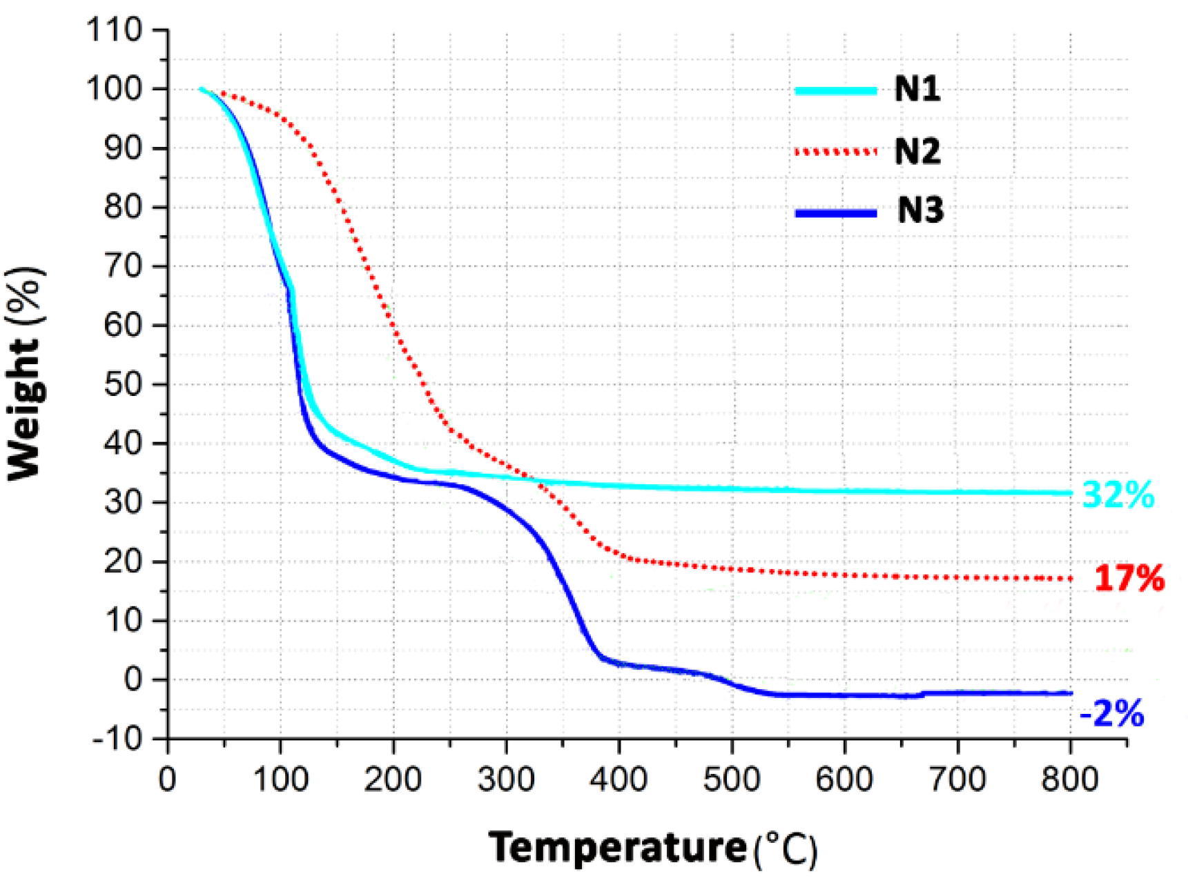
For the three nanomaterials, its chemical composition was obtained by an X-ray fluorescence (XRF) analysis and a thermogravimetric analysis (TGA).
Table 3 shows the results of the XRF analysis, and
Figure 5 shows the results of the TGA.
As can be observed in
Table 3, the composition of N1 was mainly silicon and sodium, elements that form the nano-sized sodium silicates that make up this material. N2 and N3 were composed only of silicon as the main element and traces of the other elements. This sodium is dissolved in the form of organosilanes in N2 and in the form of an acrylic copolymer in N3.
The results of the TGA analysis are shown in
Figure 5. In N1, a progressive weight loss was observed of up to 200 °C, which was due to the loss of water in the nanosilane. This nanomaterial showed a high silica content of 32%. N2 showed a higher weight loss; the silica content at 400 °C was 17%. N3 completely loses its mass at a temperature of 400 °C.
The higher stability of silica in the form of sodium silicate compared to other solutions, such as organosilanes or acrylic copolymers were observed, organosilane compounds lost 83% of their mass and acrylic compounds did not retain their mass after the test.
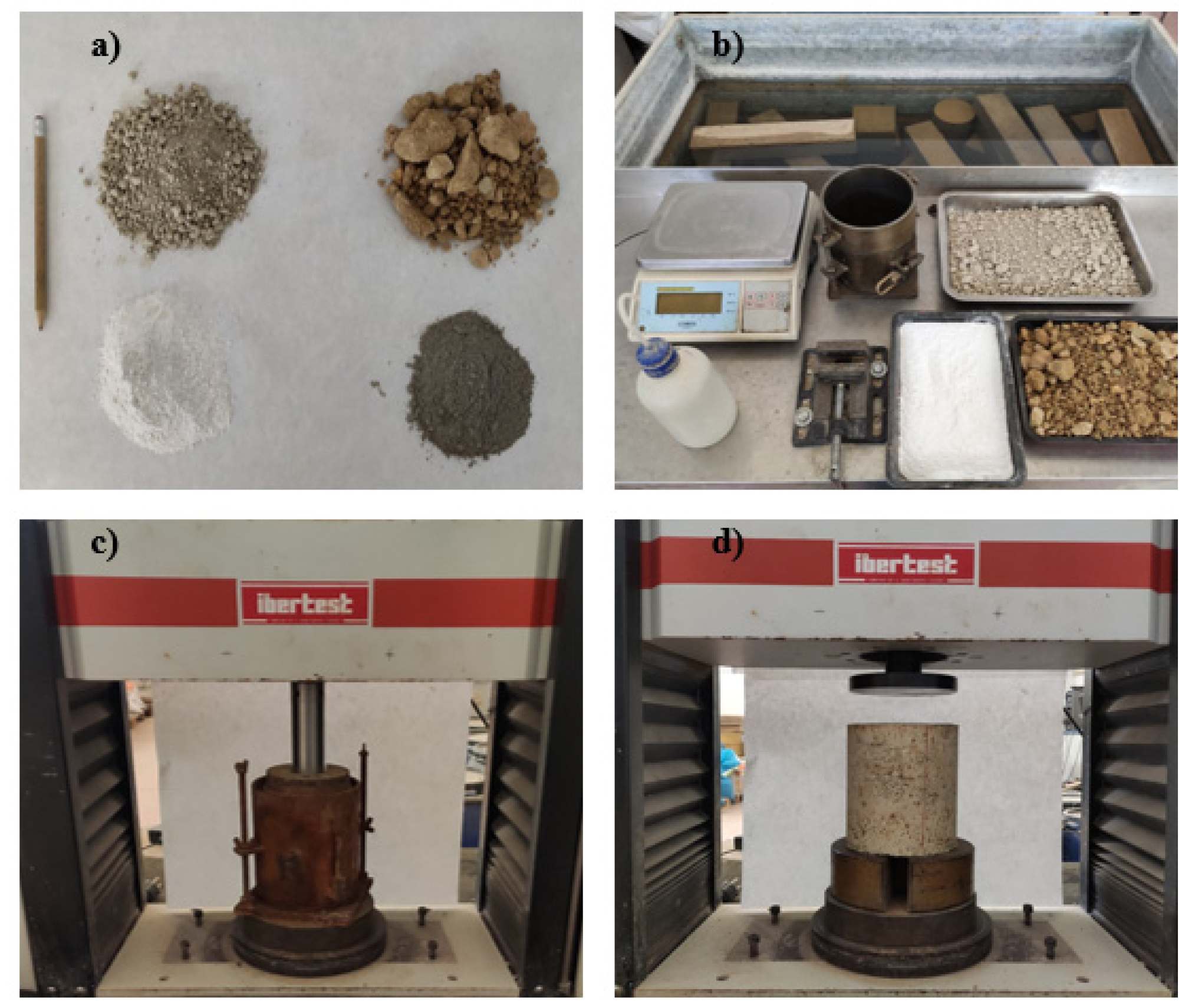
4.2. Phase 3: Mechanical Behaviour of Soil Mixtures
In this section, the requirements for the thickness layer designs are determined. The Modified Proctor compaction test, California Bearing Ratio (CBR), unconfined compressive strength and shear test are performed and shown.
Figure 6 shows photographs of the experimental methods and materials applied in this work.
4.2.1. Mix Design
Six mixes of soil with binders and/or nanomaterials were defined to design the three alternative innovative sections studied in this article.
Table 4 shows the mixtures analysed in the laboratory, the dosage of each material and its designation.
The dosages of the mixtures shown in the table above are expressed in weigh (kg) per cubic metre of material.
Each material was added emulating the real process of road construction:
Quicklime was added to the dry mass of CS in all mixtures. OPC was added to the total dry mass of soil (CS and SS), and nanomaterials were added to the dry volume of CS.
Finally, AM-1, AM-2 and AM-3 were composed of 0.40 m3 of CS and 0.60 m3 of SS per one cubic metre of the total mix.
The AM mixes were made with a special manufacturing process, which is explained below:
Step 1. Forty percent in volume of CS was mixed with an addition of 1.5 w% of quicklime (AM-1), 1.5 w% of quicklime plus N1 (AM-2) or 1.5 w% of quicklime and N2 plus N3 (AM-3). The mixture was compacted according to the Modified Proctor compaction test and stored in a wet chamber with a minimum moisture of 90%.
Step 2. One day after compaction, the mixture was decompressed into particles with a size smaller than 25 mm.
Step 3. The stabilised CS was mixed with 60 v% of SS and 1 w% of OPC compared to the total dry mass of soil. The mixture was compacted according to the Modified Proctor test and stored in a wet chamber (compressive strength and shear tests) or curing tank (CBR test) before the samples were tested.
4.2.2. Compaction Test: Modified Proctor
The level of compaction is a key parameter in road layer construction. A proper compaction ensures the strength and durability of the road; conversely, if the road has not been adequately compacted, it becomes unstable, which can result in a possible differential settlement. Settlement in a road implies pavement deformation and cracking that, added to storm water infiltration, causes a serious impact on traffic and road safety [
35].
Compaction is studied through the moisture–dry density relationship, which is determined according to the Modified Proctor Test, UNE EN 103501: 1994 standard.
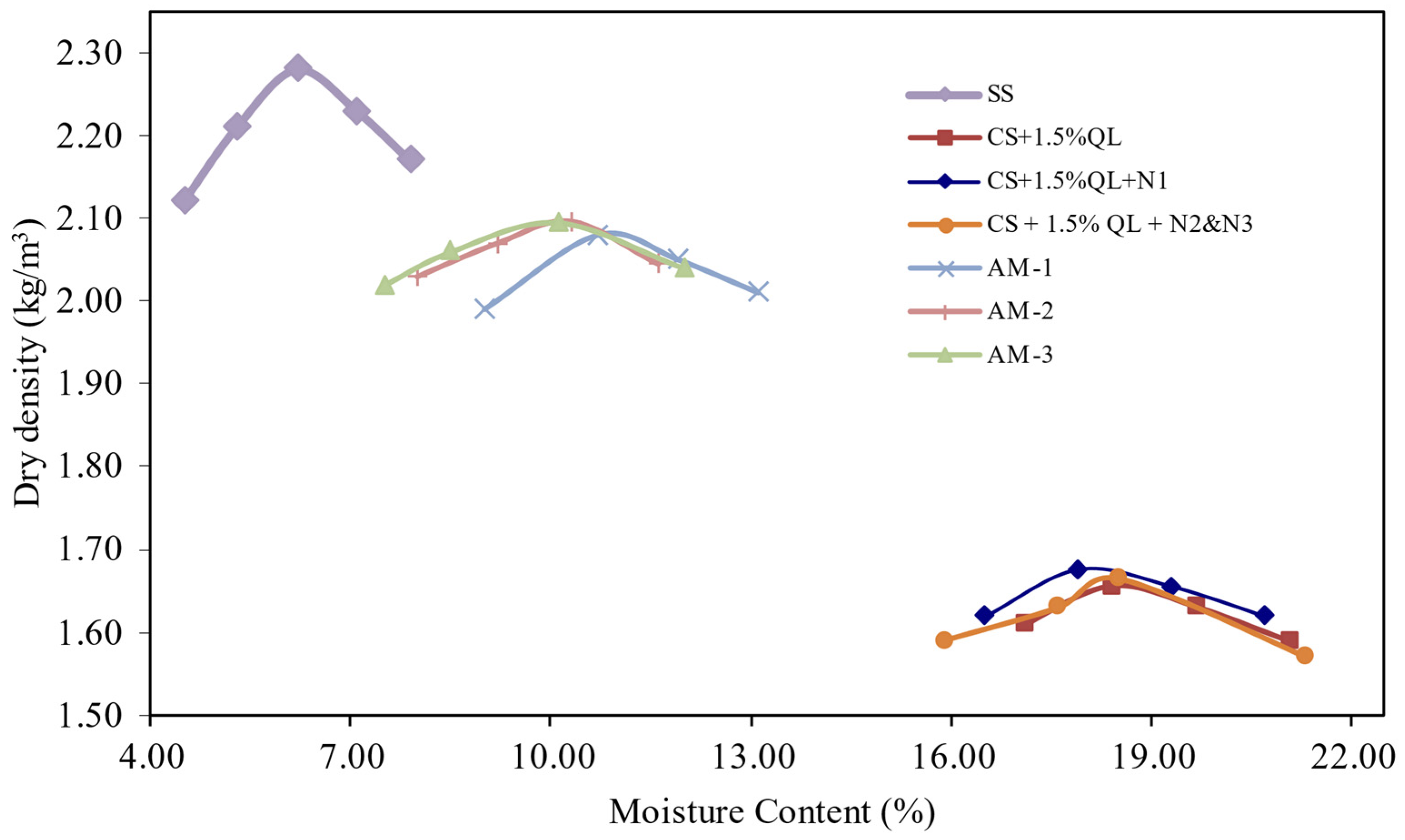
The moisture–dry density relationship, which is shown in
Figure 7, is a very useful tool for understanding compacted soil behaviour. The maximum dry density to the optimum moisture content is obtained, which allowed the samples made to achieve the optimal mechanical behaviour. Additionally, the curve shape indicates the sensitivity of the soil to the water addition. If the curve is flatter, the maximum dry density is less affected by moisture changes; however, if the curve is sharper, small changes in the moisture content greatly affect the maximum dry density [
36], as can be observed in
Figure 7.
Analysing
Figure 7, SS shows the highest maximum dry density, 2.28 kg/m
3, and minimum optimum moisture content, 6.2%, likely due to its physical properties, such as a higher quantity of coarse particles and its higher density. However, CS stabilised with lime and quicklime plus nanomaterials show values contrary to SS due to the clay gradation, which is composed mainly of fine particles and its great absorption of water, which is a typical characteristic of expansive soil.
As can be observed, the addition of nanomaterials in the amount used in this article (0.056 w% N1 and 0.12% N1&N2) shows a low effect on the compaction parameters, especially for the dry density, which is consistent with the results obtained in previous studies of soil stabilisation with nanoparticles [
29].
However, Alireza et al. [
37] showed a decrease in the maximum dry density and an increase in the optimum compaction humidity in a soil stabilised with 5% lime from nano-SiO
2 additions greater than 1%.
Finally, the AM-1, AM-2 and AM-3 mixtures have an intermediate behaviour among the materials that compose them. A slight increase in the maximum dry density due to the addition of nanomaterials was observed in the AM-2 and AM-3 mixtures, likely due to the interaction of the stabilised soils with nanomaterials and the OPC.
4.2.3. Design Parameters: California Bearing Ratio (CBR) and Compressive Strength
The structural behaviour of the road layers is determined by the load bearing capacity. According to the type of road layer executed, this bearing capacity is measured according to the CBR (California Bearing ratio) or unconfined compressive strength.
The CBR index measures the bearing capacity of soils and compacted aggregates used in the construction of road bases or subbases. The CBR index depends on the density and moisture conditions of the samples. In this study, the samples were compacted according to the optimum moisture obtained in the Modified Proctor Test to reach the maximum dry density and the highest possible bearing capacity. The CBR value is carried out in accordance with UNE 103-502.
The unconfined compressive strength (UCS) was performed according to the NLT-305/90 standard in specimens 177.8 mm high and 152.4 mm in diameter. The UCS measured the resistance in cohesive soil or cement treatment soil or granular materials. Like the CBR samples, these samples were manufactured under the optimal compaction conditions obtained in the Modified Proctor Test.
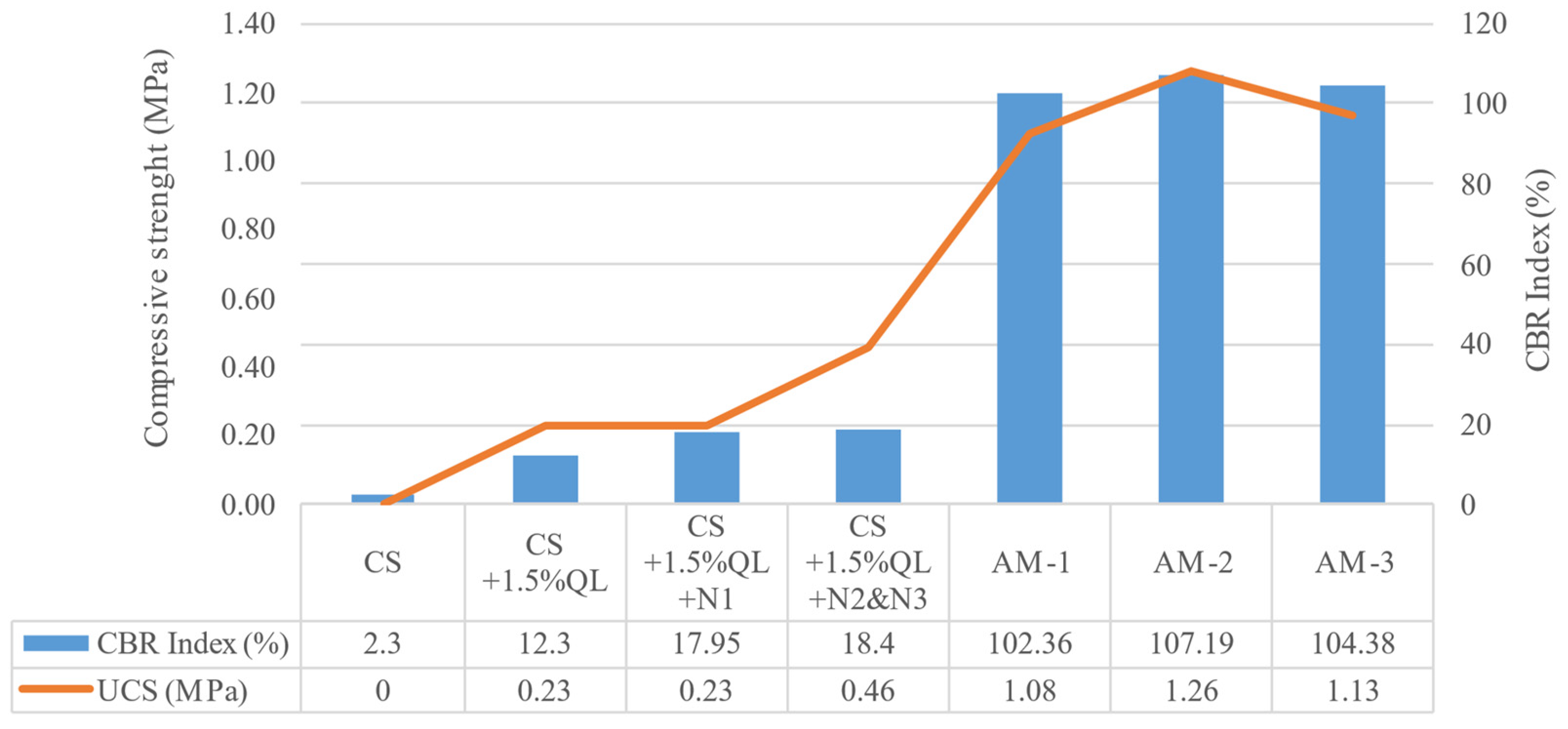
Spanish specifications [
34] establish that lime-stabilised soil must comply with the minimum CBR index; however, cement-treated soil must exceed a minimum value of unconfined compressive strength. The results obtained in the laboratory test are shown in
Figure 8.
Analysing the results shown in
Figure 8, the use of different nanosilica improve the bearing capacity of soils.
The addition of 0.056 w% of N1 and 0.112 w% of N2&N3 increase the CBR index by 31.5% and 33.2%, respectively.
Similar increases in the CBR index have been observed in previous studies [
38] with similar dosages, probably due to the reactions of these nanomaterials with cement and the soil minerals themselves, leading to pozzolanic cementitious reactions. This behaviour has been observed in previous studies with higher increases in the bearing capacity or simple compressive strength, due to the higher addition percentages of the nanomaterials, between 1 and 7% [
37,
39].
The AM-1, AM-2 and AM-3 mixtures showed similar CBR index values, in the order of 100% of the CBR index with slightly higher values in the mixtures with nanomaterials, which shows an excellent bearing capacity. At the same time, unconfined compressive strength values of between 1.08 and 1.23 MPa were obtained, relatively high values for mixes with a total of 1 w% cement, normal values for stabilisation being a minimum of 3%, according to Spanish specifications [
34].
5. Phase 4: Trial Sections Structural Design
In this section, the design of three trial sections based on the results obtained in laboratory tests are shown.
Three alternative sections (AS) were designed to reduce the thickness of the control section analysed by Rosales et al. [
32], while the mechanical and durability properties of the current section were maintained or improved.
To guarantee the adequate structural performance of the alternative sections, a calculation process was carried out using Everstress 5.0 software. The maximum load capacity of the control section, measured in the maximum number of standard axles of 13-tonne-heavy vehicles, was determined and compared with the alternative sections, which must present a value equal to or greater than the control section.
To determine the maximum number of equivalent single axle loads of 13 tonnes, the following methodology was followed:
- (1)
Determination of the elastic modulus (E) of the layers from the CBR index or compressive strength according to the type of material and its mechanical behaviour.
- (2)
Calculation of the vertical deformations in the subgrade using Everstress 5.0 software.
- (3)
Calculation of the number of equivalent axles according to the fatigue law described by the Spanish specifications [
40] according to Expression (1).
= unit vertical deformation in the subgrade.
= number of equivalent axles of 13 tonnes.
In the first place, the calculation of materials with a reduced CBR, such as soil from the construction site or stabilised or granular materials that do not present significant compressive strength, was accomplished by the Transport and Road Research Laboratory method [
41], which is in accordance with the study of different bibliographies that indicate that the application of this method is appropriate for materials with CBR of less than 10% and without unconfined compressive strength.
The formula of Powell et al. [
41] for stabilised materials and unbound granular materials was applied according to Expression (2).
Furthermore, with soils in which the CBR results were increased, a compressive strength test was carried out beforehand. The elastic modulus of these soils that present CBR values greater than 20% and a compressive strength greater than 0.2 MPa was calculated by the Molenaar equation. This equation considers the unconfined compressive strength as the main modulus calculation parameter.
The formula of Molenaar [
42] for materials treated with binders was applied according to Expression (3).
Table 5 shows the elastic modulus of the analysed mixtures according to the expression shown above.
Once the elastic modulus of the materials that make up each layer were determined, they were entered into the software, together with the thicknesses of each layer and with a stress of 800 kPa, in accordance with Spanish regulations.
First, the conventional section was analysed, which presented a bearing capacity of approximately 75,000 equivalent axels.
Subsequently, three series of alternative sections (AS): AS-1, AS-2 and AS-3 of 45 cm, 50 cm and 55 cm, maintaining the proportion of 40% CS and 60% SS of the design mixes, were analysed.
Table 6 shows the results obtained for the vertical deformation of the subgrade and the number of equivalent axels for each solution.
As is observed in
Table 6, the 45-cm section series structural capacity was insufficient and was therefore rejected.
The 55-cm series exceeded by three times the required capacity of 75,000 equivalent axels and was therefore rejected in order not to oversize the section.
Therefore, the thickness of the section was 50 cm, due to a higher structural capacity than the control solution and a reduction in the section thickness of 30 cm.
6. Phase 5: Construction and Section In Situ Tests
6.1. Trials Sections Execution
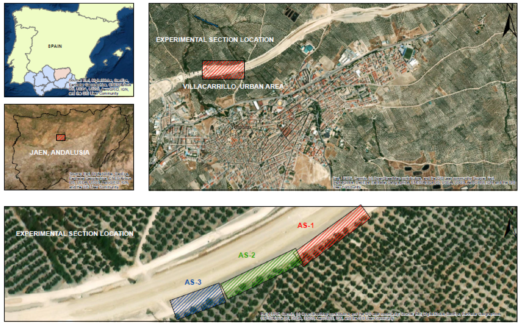
After the design phase, the three trial sections of 50-cm total thicknesses were constructed, with a length of 100 m for alternative sections 1 and 2 (AS-1 and AS-2) and a length of 50 m for alternative section 3 (AS-3).
The three trial sections were built near the newly built road in Villacarrillo, Jaén, Spain, [
32] and the performance of the AS was compared with the control section, which was used alongside the layout of the road.
Figure 9 shows the control section and the location of the trial section.
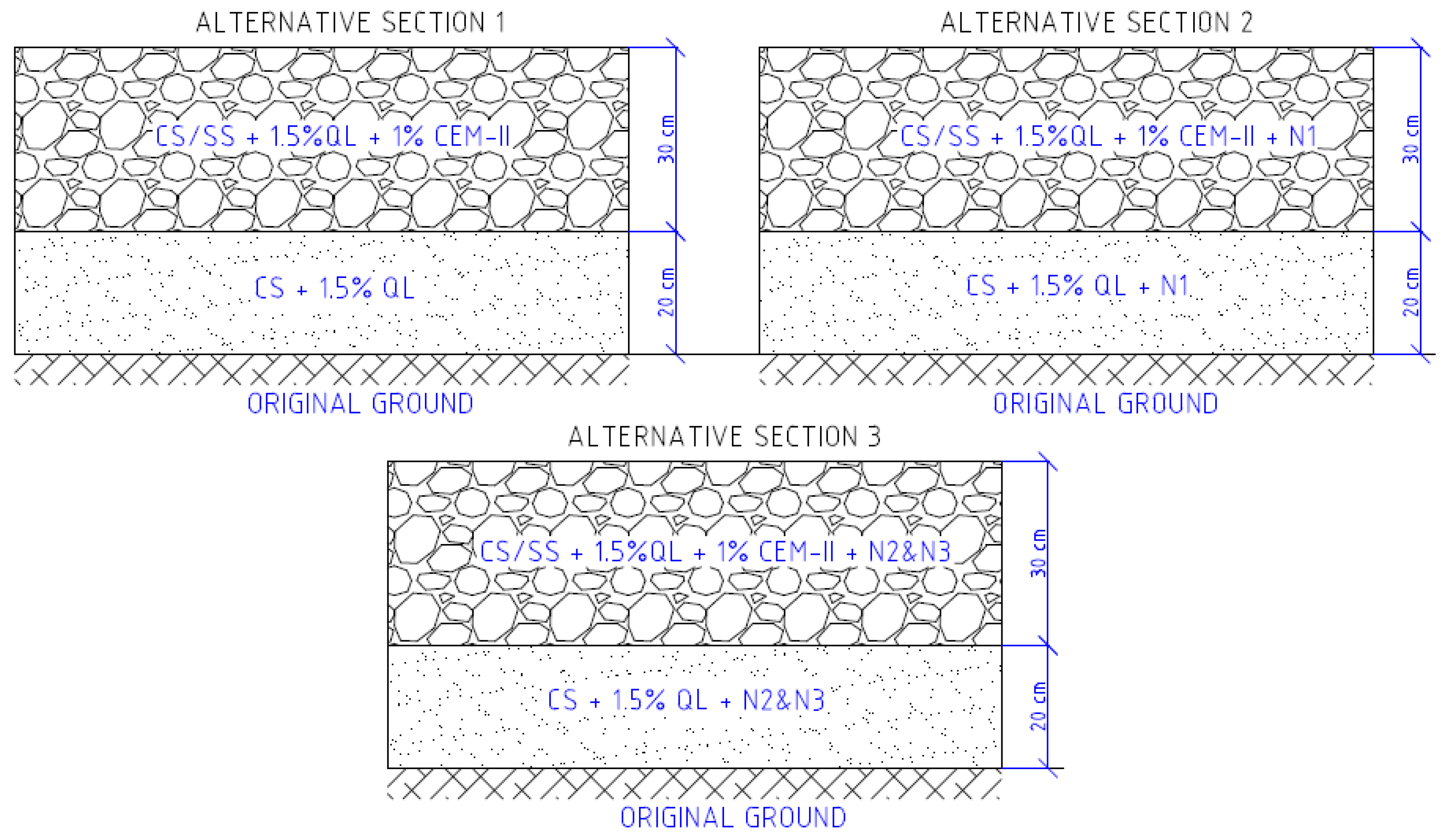
The final solutions were as follows:
- -
Alternative section 1 (AS-1). Thirty centimetres of CS (40%) stabilised with 1.5% lime, and SS (60%) stabilised with 1% CEM-II over the total soil (CS+SS) carried out according to the process described in
Figure 1 over a 20-cm layer of CS stabilised with 1.5% quicklime.
- -
Alternative section 2 (AS-2). Thirty centimetres of CS (40%) stabilised with 1.5% lime and 0.056% N1, and SS (60%) stabilised with 1% CEM-II over the total soil (CS+SS) carried out according to the process described in
Figure 1 over a 20-cm layer of CS stabilised with 1.5% lime and 0.056% N1.
- -
Alternative section 3 (AS-3). Thirty centimetres of CS (40%) stabilised with 1.5% lime and 0.12% N2&N3, and SS (60%) stabilised with 1% CEM-II on the total soil (CS+SS) made according to the process described in
Figure 1 on a 20-cm layer of CS stabilised with 1.5% lime and 0.12% N2&N3.
Figure 10 shows a scheme of the developed sections.
6.2. Trial Sections Survey
According to Spanish specifications [
33], three categories of subgrades, according to the equivalent elastic modulus, are stabilised: low quality, 60–120 MPa; medium quality, 120–300 MPa and high quality, greater than 300 MPa.
For rural and low-volume roads, a low-quality subgrade with a modulus between 60 and 120 MPa is structurally valid; however, due to the control section being designed as a medium-quality subgrade, this criterion was maintained for the test sections, setting a minimum of a 120-MPa equivalent modulus.
To determine and compare the equivalent modulus value, the following methods were analysed.
Analysis of the theoretical deflection produced by a 500-kPa applied on a 300-mm-diameter plate in a multilayer elastic model, the method specified in Spanish regulations [
40]. The theoretical equivalent modulus value per section was obtained.
Analysis of the deflections measured in the falling weight deflectometer (FWD) test. The average equivalent modulus value of the section was obtained.
Analysis of the second load cycle in the plate bearing test. A point value of equivalent modulus per section was obtained.
Table 7 shows the results obtained in the Everstress 5.0 program, analysing the multilayer elastic model with a stress of 500 kPa applied on a 300-mm-diameter plate. Applying Formula (4) [
40], the equivalent modulus of compressibility of each section,
Ev, was determined.
As can be observed in
Table 7, the three alternative sections present a sufficient theoretical equivalent modulus to be considered a medium-quality subgrade.
Once the theoretical equivalent modulus values for each section have been obtained, they are verified with the values obtained in the in situ tests, FDW and plate bearing test.
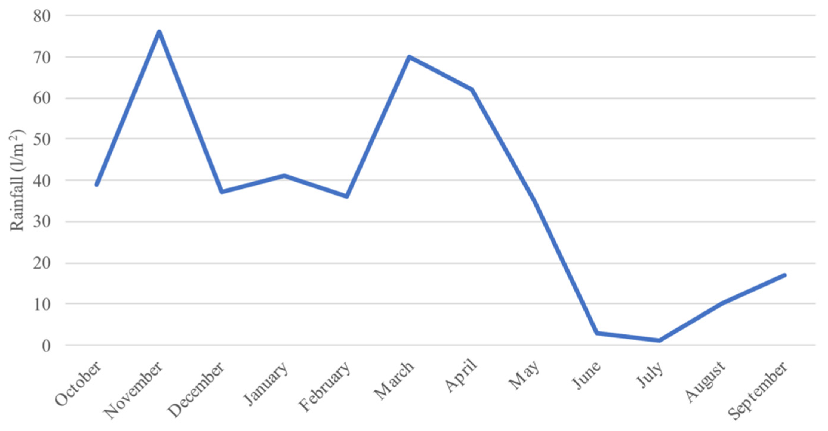
As
Figure 11 shows, the climatology of the area shows two distinct annual seasons, with 6 months with abundant rainfall and 6 dry months [
43]. Therefore, two in situ test campaigns were carried out: the first in July 2020 in the dry season and the second in March 2021 in the wet season.
Once the data for both periods was obtained, the average annual value of equivalent modulus was obtained for each of the methods.
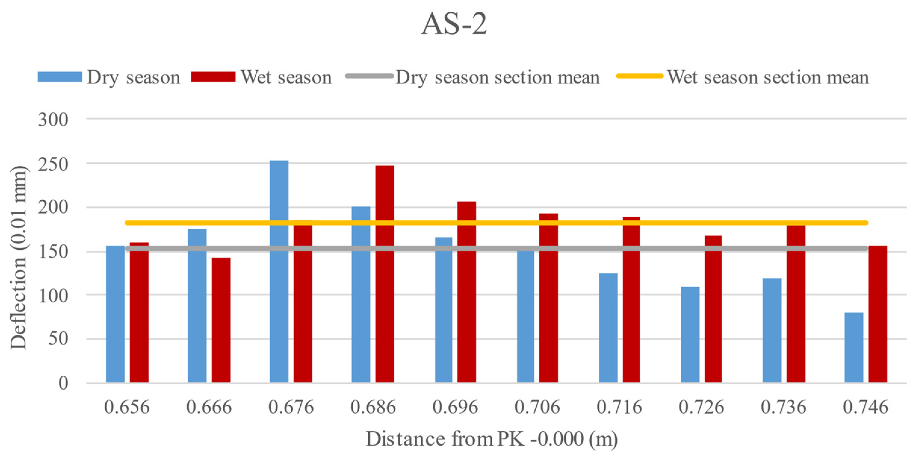
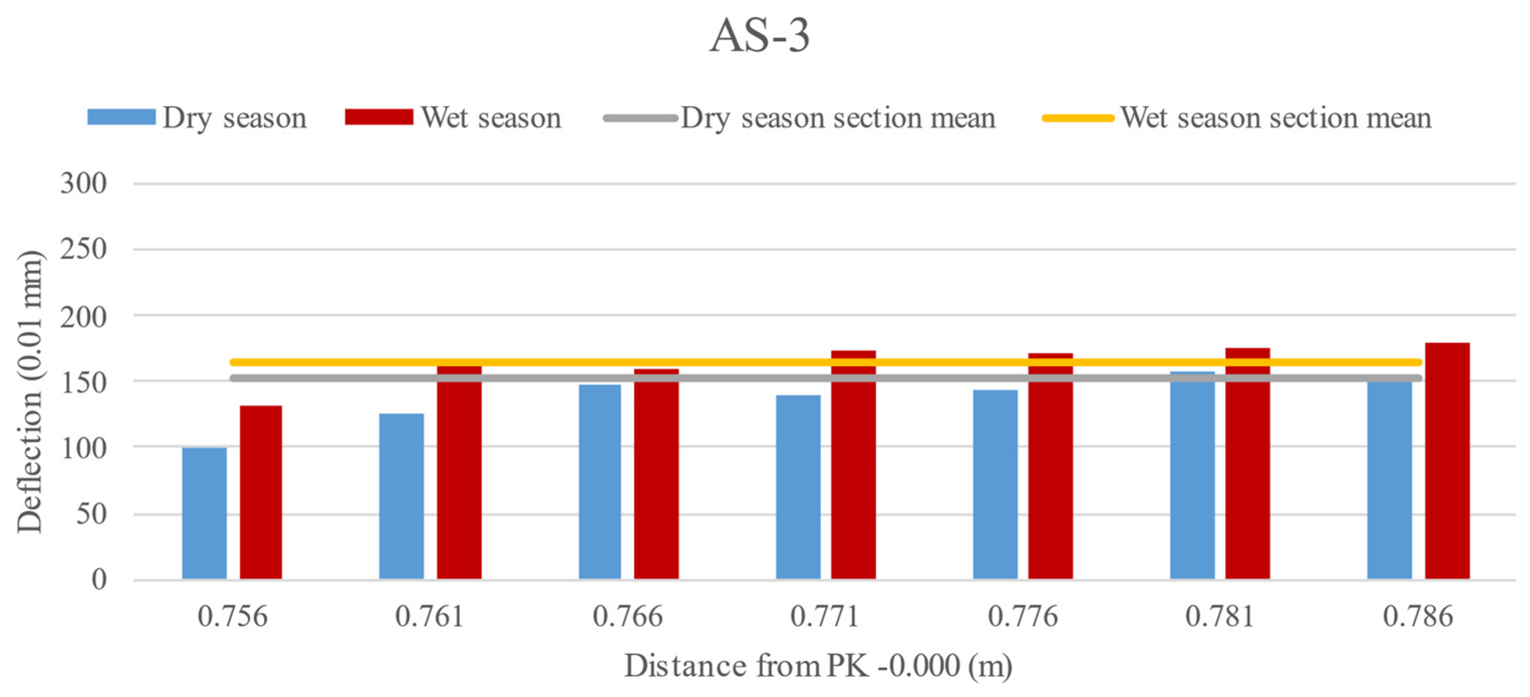
6.2.1. Deflection Measurements by FWD
The deflection measurement enables characterising the structural capacity of the formed subgrade, as well as its layers along the road layout. A Dynatest HDW 8081 falling weight deflectometer (FWD) was used.
A pressure of 850 kPa was applied through a 300-mm-diameter plate. The surface deformation due to the application of this load was measured by seven geophones located at 0, 300, 450, 600, 900, 1200 and 1500 mm from the application of the load.
Surface deformation measurements were taken every 10 m in sections AS-1 and AS-2 and every 5 m in section AS-3 in both lanes, obtaining the average per section.
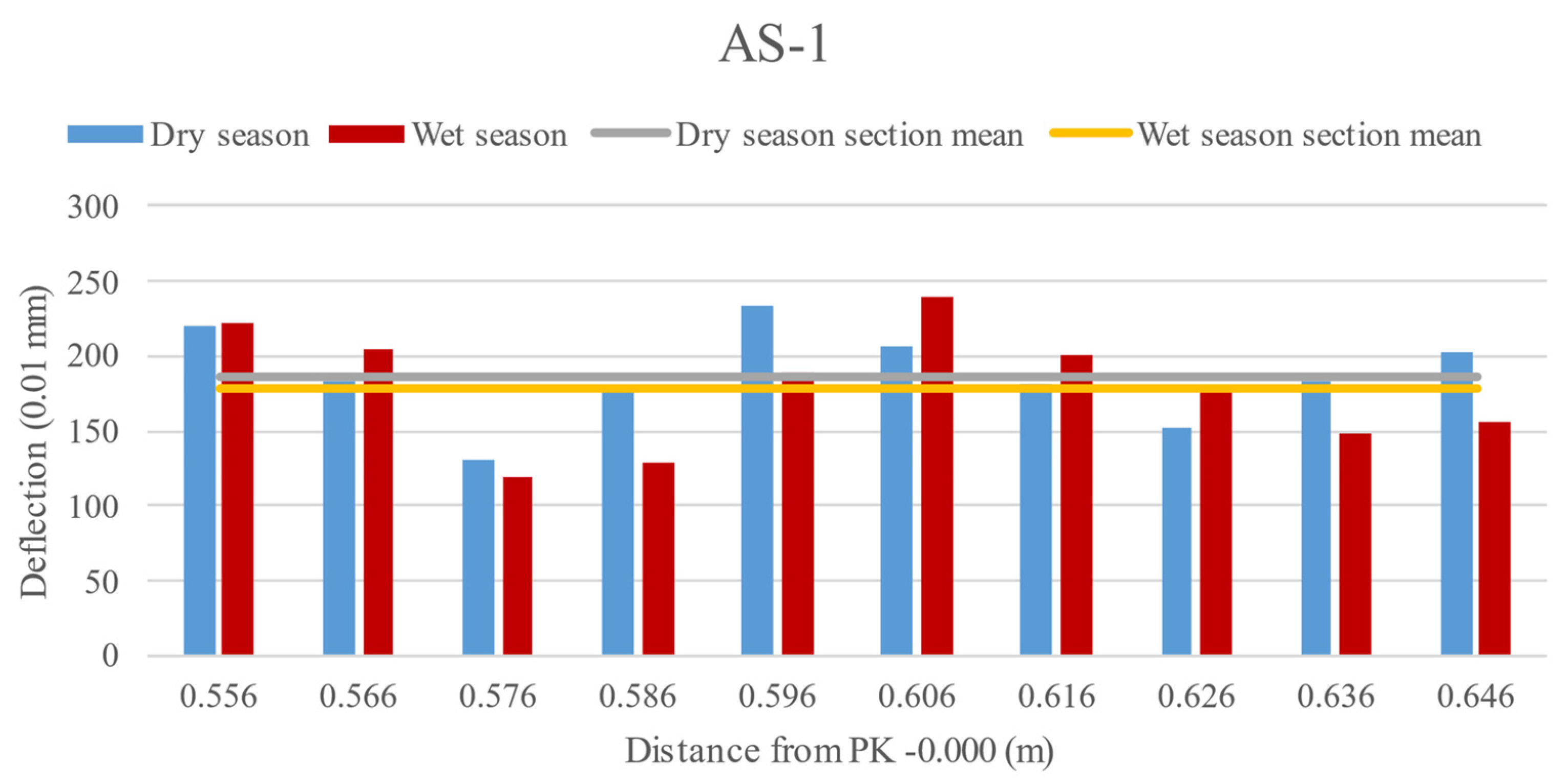
Analysing
Figure 12,
Figure 13 and
Figure 14, two patterns of behaviour were observed: firstly, the addition of nanomaterials, both sodium silicates and organosilanes, together with acrylic copolymers, improved the bearing capacity of the soil, reducing the deflections measured during the test.
Secondly, the sections with nanomaterials showed a drop in the bearing capacity due to rainfall, in contrast to the AS-1 section, which remained practically constant after a year’s weather.
However, the AS-1 section showed greater dispersion in the data, which could be attributed to problems during the execution of the work, presenting over-compacted areas that reduce the average deflection of the section.
Table 8 shows the average annual deflection of each section, as well as the weighted deflection for a load of 500 kPa, which enables calculating the elastic modulus through Equation (4).
As is shown in
Table 8, the average values of the sections show a reduction in the average annual deflections and an increase in the equivalent modulus of the sections made with nanomaterials.
Comparing the deflection results obtained for the new hybrid stabilised sections, a better behaviour was observed than the alternative section analysed by Rosales et al. [
32], and a slight drop was observed when compared to the 80-cm-thickness control section. However, a section reduction of approximately 40% and a similar mechanical behaviour confirmed the suitability of the proposed method of hybrid stabilised solutions for road layers.
All the sections can be classified as in the medium category, although with lower values than those obtained theoretically, due to the irregularities of the terrain and construction peculiarities of the linear works.
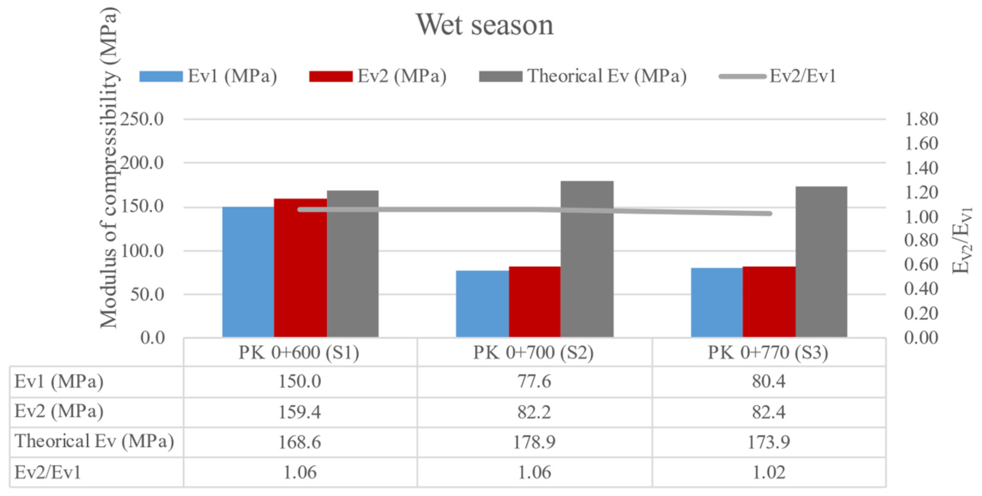
6.2.2. Plate-Bearing Test
The plate loading test is an in situ test used to measure the final bearing capacity of the subgrade built from the sections designed through its compressibility modulus.
The plate bearing test was performed according to UNE 103808:2006, and it consists of measuring the settlement of a rigid circular plate resting on the ground, subjected to different loads in a staggered manner, called the load cycle. This circular-shaped plate has a surface area of 700 cm2 (diameter 298.5 mm), and the measurements enable determining the compressibility modulus in the first load cycle (Ev1) and in the second load cycle (Ev2).
The plate bearing test enables the calculation of the punctual behaviour of the section in the place where the load was applied, so its result was not as representative as those obtained in FDW; however, it enables verifying the behaviour of the subgrade and analysing its evolution over time.
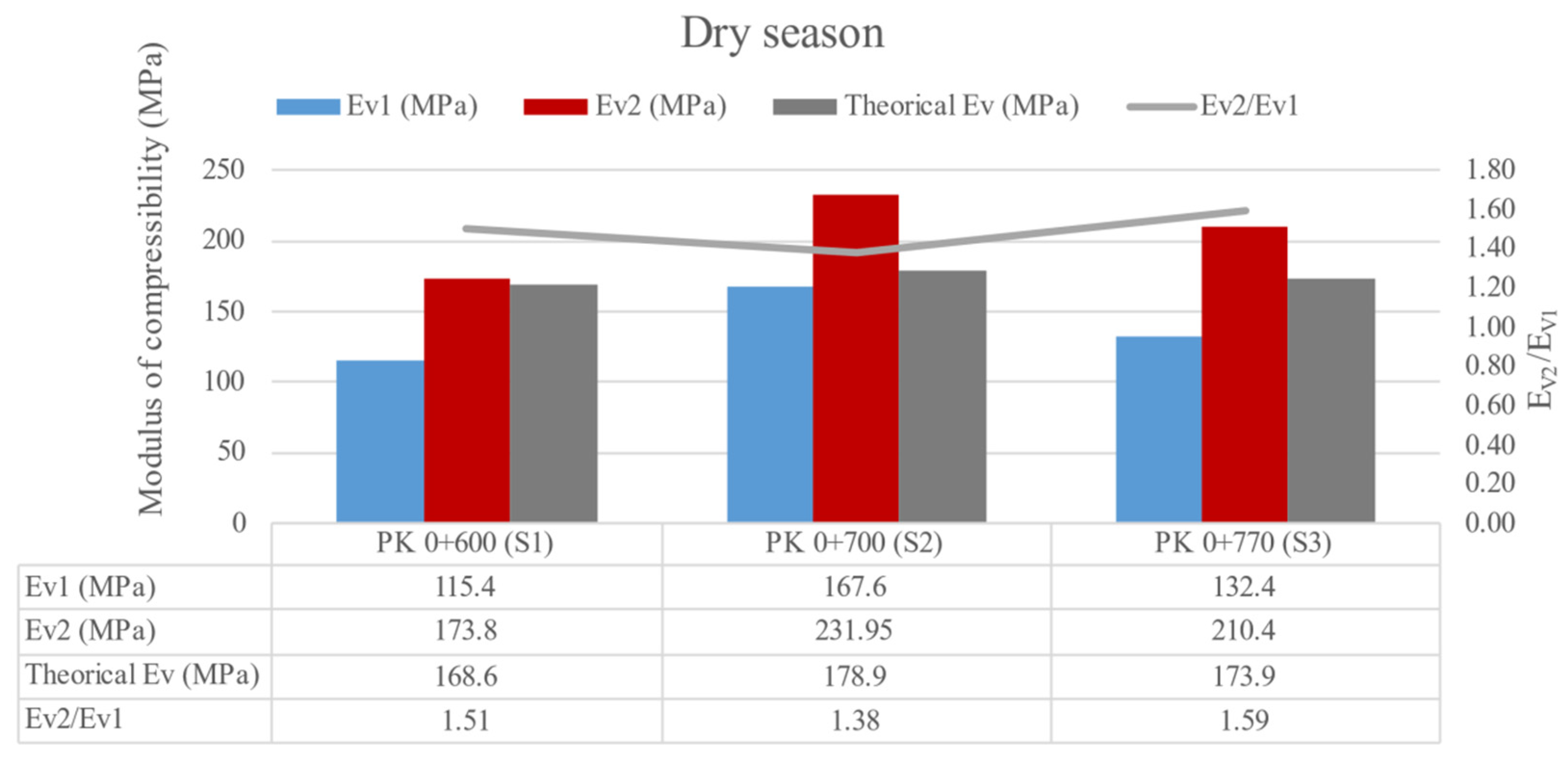
As is shown in
Figure 15, all the sections presented a medium quality, which verified the adequate structural behaviour in relation to the volume of the loads the sections will support during their useful life.
An improvement in the quality of subgrades AS-2 and AS-3 was observed due to the addition of nanomaterials, similar to that observed in the FDW results.
Analysing
Figure 16, a drop in the equivalent modulus was observed in all three sections due to the rainy period; however, this drop was greater in sections AS-2 and AS-3 than AS-1.
This sharp drop may be due to a lack of bearing capacity in some of the layers that make up the section because of the rain or perhaps a specific problem associated with the uncertainty of the plate loading test.
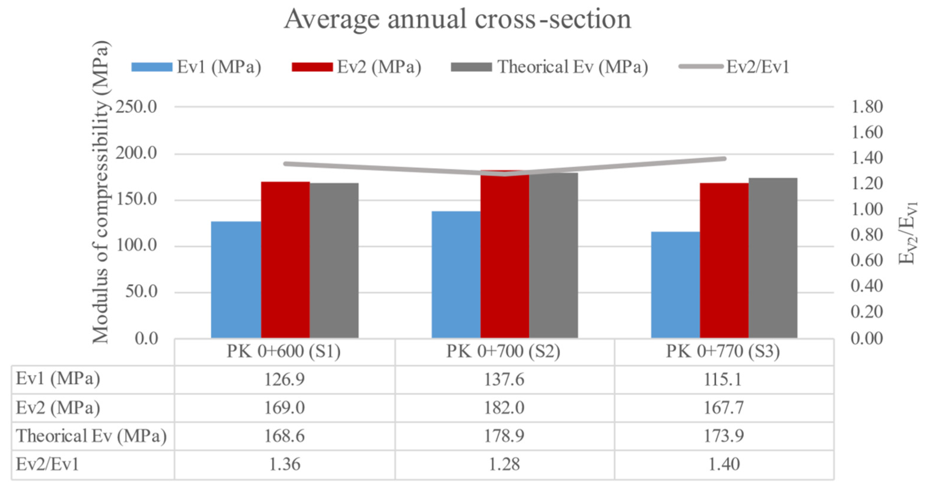
Finally,
Figure 17 shows the average annual behaviour of the sections. Despite the large drop observed in the rainy weather for sections AS-2 and AS-3, an adequate mechanical behaviour was observed, being practically identical to that obtained in the theoretical analysis using the multilayer elastic model, which confirms the validity of the multilayer elastic method used and the validity of the sections constructed.
Comparing the results with those obtained by Rosales et al. [
32], an increase in the modulus of the compressibility of the current hybrid sections was observed. This increase confirmed the adequate behaviour of the new solutions constructed with a reduction of the input materials.
Additionally, the evolution of the Ev2/Ev1 ratio was shown, limited by Spanish specifications to 2.2, a limitation that was met by all sections in both the dry and wet seasons.
7. Conclusions
In this work, the construction of trial sections based on hybrid stabilised soils with small amounts of lime, cement and nanomaterials was studied. For this purpose, an in-depth laboratory study was carried out to determine the physicochemical properties of the materials and the mechanical behaviours of the mixtures of stabilised soil. A structural design of the trial sections was carried out through a multilayer elastic model. Finally, the sections were built in a real-scale application, and their short and medium-term in situ properties were monitored.
The following conclusions have been drawn from this study:
The stabilisation of soils with nanosilica slightly increases the maximum dry density of the samples and slightly reduces their optimum water content. A reduction in the optimum water content implies a reduction in the consumption of natural resources (water, fuel, less CO2 emissions, etc.) to achieve the same or higher degree of compaction.
The addition of nanosilica improves the bearing capacity of the stabilised soils as measured by the CBR index. The nanomaterial N1, composed of sodium silicate, shows a higher reactivity in combination with cement, increasing the unconfined compressive strength.
The proposed hybrid stabilisation solution reduces the thickness of the control section by 37.5% and increases the bearing capacity measured in the number of equivalent axles by up to 25%.
The sections built with N1 and N2&N3 show an improvement in the annual mean equivalent modulus of compressibility, with these sections showing a greater drop in bearing capacity during the rainy season.
The results support the application of the developed alternative solutions with a hybrid stabilisation process due to their increased bearing capacity for rural and low-volume roads. However, due to the typical climatic conditions in Southern Spain, there is no evidence of effectiveness in the other conditions. In countries with high humidity and large temperature differences, the solution should be verified.
As a general conclusion, the use of nanomaterials in percentages between 0.06 and 0.12% improves the mechanical behaviour of stabilised soils and allows a reduction in the thickness of the road layer, improving its general structural capacity, although there is a drop in capacity during rainy periods, which will be the subject of future studies.


 ,
, 


