Abstract
This study investigates the decomposition of methane using solar thermal energy as a heat source. Instead of the direct thermal decomposition of the methane at a temperature of 1200 °C or higher, a catalyst coated with carbon black on a metal foam was used to lower the temperature and activation energy required for the reaction, and to increase the yield. To supply solar heat during the reaction, a reactor suitable for a solar concentrating system was developed. In this process, a direct heating type reactor with quartz was initially applied, and a number of problems were identified. An indirect heating type reactor with an insulated cavity and a rotating part was subsequently developed, followed by a thermal barrier coating application. Methane decomposition experiments were conducted in a 40 kW solar furnace at the Korea Institute of Energy Research. Conversion rates of 96.7% and 82.6% were achieved when the methane flow rate was 20 L/min and 40 L/min, respectively.
Keywords:
methane; decomposition; hydrogen; reactor; cavity; solar thermal energy; chemical reaction 1. Introduction
The increasing reality of global warming effects owing to the burning of fossil fuels has prompted the need to invest in renewable energy sources in order to reduce greenhouse gas emissions. Of all the renewable energy sources available, hydrogen is gaining global attention as the preferred eco-friendly energy source due to its pollution-free combustion process. In Korea, for example, steps are being taken to ensure that the country becomes the leading global hydrogen economy by 2050. As a result, policies have been initiated, and studies are being conducted to guide the establishment of an industrial ecosystem based on hydrogen vehicles and fuel cells, and the creation of a hydrogen production and supply system without carbon emissions. Until recently, hydrogen was produced via steam methane reforming (SMR), as in Equation (1) [1]. However, dry reforming of methane (DRM), as shown in Equation (2), and partial oxidation of methane (POM) method, as shown in Equation (3), are currently being developed. The above methods generate COx as a by-product, which requires a separate costly process for removal. Therefore, catalytic methane decomposition (CMD), as shown in Equation (4), is a preferred alternative. To decompose methane through direct pyrolysis, a temperature of 1200 °C or higher is required; however, if the CMD method is used, a reasonable yield can be obtained while reducing the temperature considerably. In addition, carbon, a by-product generated with hydrogen, is cheaper than COx, and the separated carbon can be used by tire and paint manufacturing industries [2,3]. High temperature heat is required for the preceding four processes, and when fossil fuels are used, air pollutants, including carbon, are released. However, hydrogen can be produced without carbon emission, by supplying heat through concentrated solar energy and using the CMD process [4,5].
The catalysts used in the CMD process are largely divided into metal and carbon catalysts. Metal catalysts mainly consist of nickel, iron, and cobalt. Noble metals, owing to their excellent catalytic properties can also be used; however, this is impractical due to the high cost. Compared to the carbon catalyst, the activation temperature of the metal catalyst was lower (450–750 °C). The initial activity was high, but the stability at high temperatures was low. Although the risk of damage is lower than that of the carbon catalyst during the regeneration of the catalyst, both catalysts require separate heat supply in the process of removing deposited carbon; this process is costly and harmful to the environment, since COx is generated. Carbon catalysts have been used in CMD owing to their availability, durability, low cost, abundant porosity, and molecular activation. Due to its good stability at high temperatures, it is suitable for use in an environment where high temperature solar heat is concentrated during the day. In addition, there are several uses of carbon commercially [6,7,8]. Studies have shown that carbon black (CB) or activated carbon (AC) catalysts are mainly used as carbon catalyst materials. The initial reaction rate of the AC catalyst was high, and the amount of carbon generated before deactivation was relatively small, whereas for the CB catalyst, the initial reaction rate was low, and the amount of carbon generated before deactivation was relatively large [8,9,10,11,12,13].
The need for an efficient reactor to supply heat required for the CMD process through solar heat has encouraged several studies to be conducted on the subject matter. [2,4,7,14,15,16,17,18,19,20,21,22,23,24].
Abanades et al. developed a methane decomposition reactor consisting of a graphite tube encased by stainless steel. The reactor was directly heated by solar heat concentrated through quartz, and at 0.7 L/min, a conversion rate of 53.3–54.9% was achieved. In addition, a performance prediction model was developed and verified by comparing it with experimental results [14,15,16].
Magg et al. developed a 5 kW direct heating solar methane decomposition reactor of a cylindrical cavity shape, with quartz mounted in a circular opening. In the experiment, a combination of argon, methane, and carbon particles was injected to improve the conversion rate. A methane conversion rate of 98.8% was achieved when methane was 0.8 L/min in 10.4 L/min of the gas mixture at 1043 °C [17]. In the same reactor, Hirsch et al. added a spiral flow path to the inner wall of the reactor to rotate methane to secure residence time and develop a reactor with improved heat transfer from the high temperature wall [18]. Ozalp et al. also performed a simulation on the decomposition of methane, according to the presence or absence of a helical cavity inside the reactor, to compare its performance [19]. Yeheskel et al. developed a direct-heated volumetric reactor optimized through CFD and conducted an experiment to convert methane into hydrogen and carbon particles using a reactor characterized by high reaction temperature, quartz protection, no boundary layer separation, and directional flow [20].
Most indirect reactors are tubular. Dahl et al. developed an indirect heated reactor consisting of three concentric vertical tubes with a porous graphite tube at the innermost wall, a solid graphite tube in the middle, and a quartz fluid wall at the outer side. A secondary concentrator was installed on the front of the reactor to reflect light from a 10 kW solar furnace. In their experiment, a methane conversion rate of 90% was achieved at 1860 °C, with a methane flow rate of 1 L/min [21].
Rodat et al. also developed a 10 kW reactor. A concentrated solar heat was passed through the opening, the graphite tube reactor located in the graphite cavity was heated, and the methane was passed through the tube and separated in a high temperature environment. In addition, heat transfer and reaction were calculated through heat flow analysis, and compared with the experimental results [22,23]. Subsequently, the experiment was performed in a 1 MW solar furnace by expanding it to a 50 kW class methane decomposition reactor. A conversion rate of 98% was achieved when the methane flow rate was 21 L/min at 1525 °C [24]. Valdes-Parada et al. developed a reactor in which a graphite tube was vertically mounted inside a hexahedral cavity with quartz that absorbs concentrated solar heat. The residence time was secured by improving the flow path in the reaction tube, which was annular. The reactor temperature distribution and the methane-hydrogen conversion rate were numerically analyzed at the time of supplying the argon-methane mixture, and the relationship between the temperature and conversion rate was explained by comparing the results with the experimental results [25].
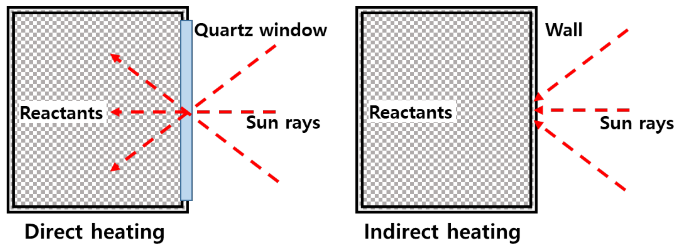
The direct heating type reactor is preferred for heating the reactants during heat transfer because solar heat is directly transferred to the inside, as shown in Figure 1. However, due to the short transmission distance between the reactor and the solar heat irradiated, there is a substantial decrease in distance within the reactor. Furthermore, carbon particles generated are deposited on the quartz, which reduces its ability to effectively transmit light. This increases the quartz temperature, resulting in damages. In addition, it is difficult to expand a reactor for treating methane with a high flow rate due to the limited size of the quartz-manufacturing process.
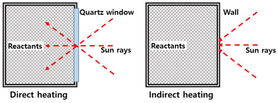
Figure 1.
Direct and indirect heating reactor.
Prior to this study, the cavity shape was modified, and the insulation performance was improved by optic and heat transfer calculation of CFD [26].
In this study, we investigate the decomposition of methane using solar heat as a heat source. Instead of direct thermal decomposition of methane at a high temperature of 1200 °C and above, methane was decomposed using a catalyst to lower the temperature and activation energy required for the reaction, and to also increase the yield. A reactor suitable for a solar thermal system was developed, and an experiment was conducted. The problems were analyzed and resolved step-by-step. Accordingly, the development process was sequentially described, and the results of the methane decomposition experiment using a reactor were compared with the results of overseas experiments.
The rest of the paper is structured as follows: Section 2 presents the experimental facilities for the solar concentrating system and methanol decomposition system. Section 3 describes the experimental process. Section 4 describes the development of the methane decomposition reactor in stages. Section 5 presents the experimental results and analysis of the reactor. Section 6 shows the comparison of the experimental results with existing literature results. Section 7 presents the conclusions of this study.
2. Experimental Facility
2.1. Solar Concentrating System
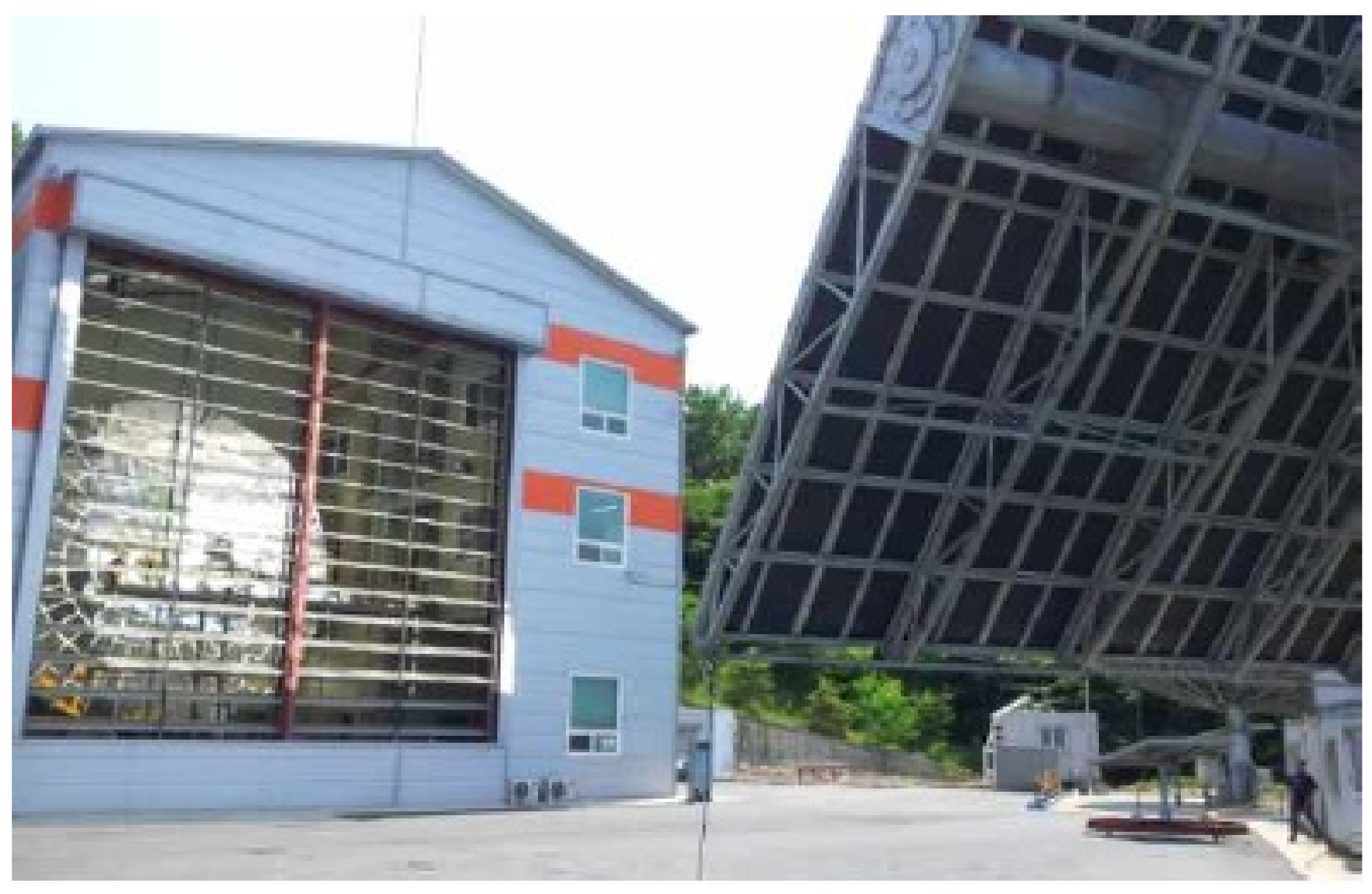
The methane decomposition reaction system using solar thermal energy consists of a solar heat-concentrating system that supplies high temperature heat, a reactor that decomposes methane by receiving heat, and a measuring device for measuring the inlet/outlet temperature, pressure, and conversion rate. For the solar heat-concentrating system, a 40 kW solar furnace installed at the Korea Institute of Energy Research was used, as shown in Figure 2 [27]. As shown in Figure 3, the solar furnace was composed of a heliostat, dish, and blind. Through a heliostat, which tracks the sun in real time, light is reflected to the dish, and is concentrated by a single focal parabola to generate high temperature heat. The blind is located between the heliostat and the dish so that the required amount of heat can be adjusted by controlling the opening ratio. The heliostat has an area of 87.3 m2, and tracks the sun by adjusting the elevation and azimuth angles through 2-axis control. The reflective area of the dish is 61.8 m2, and the focusing focal length is 4.98 m. The reflectance of the heliostat and dish was 84% and 94%, respectively. The effective area ratio by blind was 85%, and the overall optical efficiency of the concentrating system was 67.1%.

Figure 2.
40 kW solar furnace at KIER.
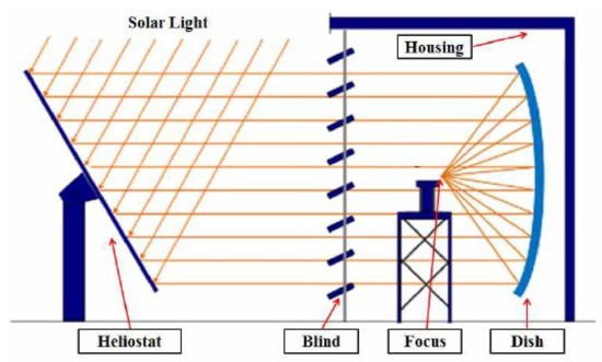
Figure 3.
Schematic diagram of the solar furnace.
2.2. Methane Decomposition System
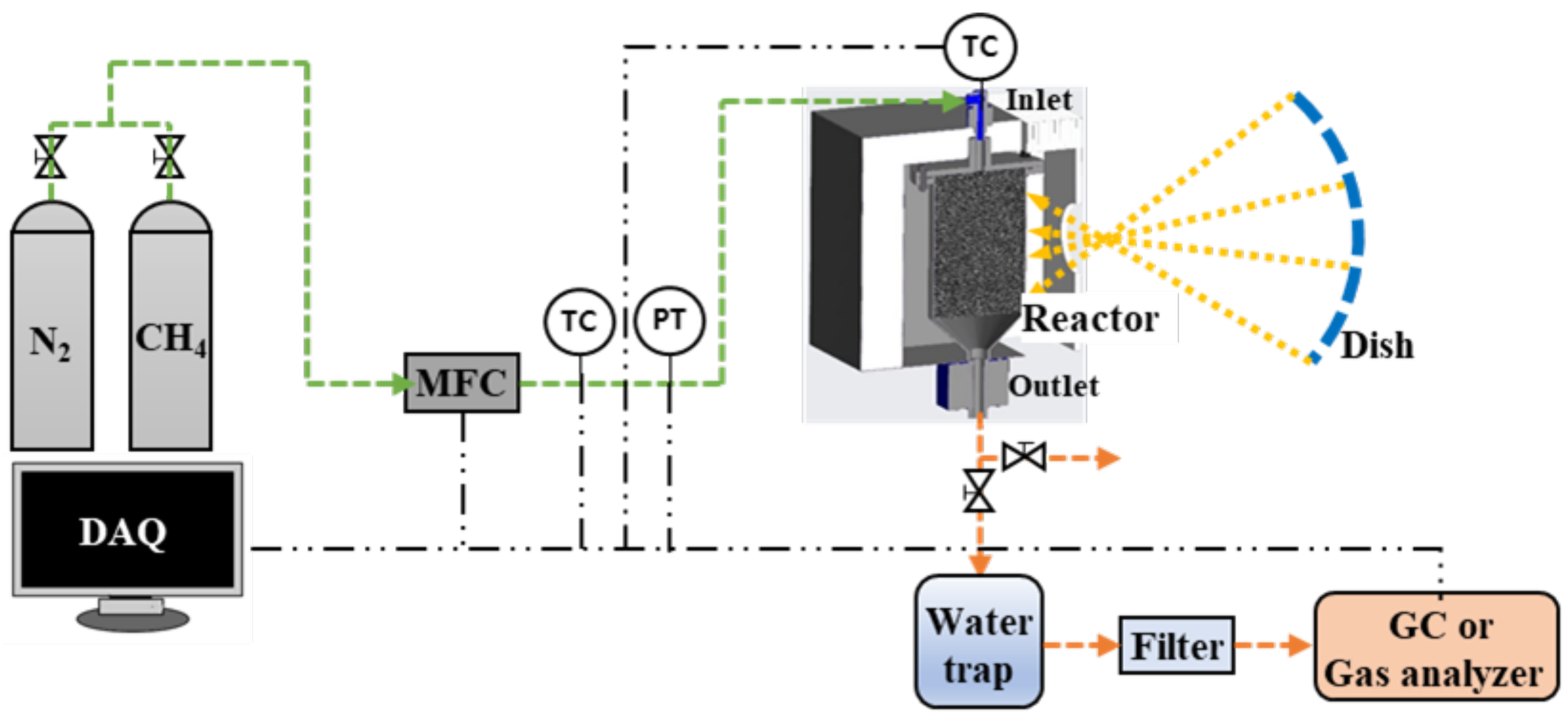
A schematic diagram of the methane decomposition experimental facility is shown in Figure 4. It is composed of a gas cylinder for supplying methane and nitrogen, a mass flow controller (MFC), a reactor with a cavity, a water trap, a filter, a gas analyzer, a pipe, and a data acquisition system. The main pipe size is 1 inch, and the flow range of the MFC is 0–90 L/min. The reactor inlet pipe was equipped with a k-type temperature sensor, and a pressure transmitter capable of measuring 0–5 bar pressure. In addition, thermocouples were installed inside the reactor to change the operating conditions by measuring the internal catalyst temperature, according to the flow rate and amount of heat supplied. At the outlet side of the reactor, a water trap and a filtration filter were sequentially connected to collect carbon generated in the reactor. Gas chromatography (GC) (model: Acme 6000) or a real-time analyzer (model: NOVA Prime), which can measure the methane-hydrogen conversion rate through component analysis of the exhaust gas, was also connected.

Figure 4.
Schematic diagram of the experimental facility.
3. Experimental Process
To decompose methane through the catalyst in the reactor, the temperature must be maintained at 1000 °C or higher, which is the catalyst-activation condition. To achieve this, solar heat was concentrated into the reactor through a 40 kW concentrating system, and nitrogen gas was supplied for internal heat distribution. A large amount of heat was maintained inside the reactor until an appropriate temperature was reached for conversion to methane.
When the temperature at the center of the catalyst reached 1000 °C or higher, methane was supplied to the reactor through MFC. Since the temperature of the catalyst decreased at the beginning of the conversion to methane, the opening ratio of the blind was enhanced to increase the amount of heat supplied to the reactor. Because the temperature of each position inside the reactor was different, the amount of heat supplied to the reactor was adjusted, based on the temperature of the central location where the temperature of the catalyst was the highest, and the opening ratio of the blind was adjusted within the limit of not exceeding the maximum temperature of 1200 °C. This is to protect the reactor, as the surface temperature was higher than the catalyst temperature. Therefore, the temperature outside the reactor was monitored in real time using a thermal imaging camera.
The experiment was conducted by increasing the methane flow rate, and when the methane-hydrogen conversion rate reached 80% at the target flow rate, the flow rate was decreased. To measure the hydrogen fraction in the reaction product, carbon was captured by a water trap and a filter, and subsequently supplied to a GC or gas analyzer. Because nitrogen was contained in the reaction product immediately after methane is supplied, the conversion rate was measured when the product does not contain nitrogen.
At the beginning of the study, only solar thermal energy was used as a heat source in the reactor, but in Korea, direct solar radiation was insufficient; hence, a heater was installed at the cavity, and used to increase the reactor temperature at the beginning of the experiment to compensate for the fluctuation of the daytime insolation.
4. Development of Methane Decomposition Reactor
4.1. Direct Heating Reactor
The initial reactor was a direct heating-type reactor, which used a quartz window, as shown in Figure 5. It also had a similar structure as the reactor used in the experiment where water splitting was previously performed using a catalyst coated with CeO2 [28]. To ensure that the inside of the reactor was uniformly heated, and the residence time was ensured, the conical silicon carbide (SIC) structure was placed inside the reactor to monitor the distribution of heat quantity based on the focal length. To measure the internal temperature, three thermocouples were mounted through the structure at uniform intervals along the axis of the reactor. The quartz was located between the reactor front flanges, and the part in contact with the flange used graphite sealing with high temperature durability to maintain airtightness. To reduce the thermal damage of the quartz window caused by high temperatures, a water flow path was created inside the flange to cool it. Methane was injected into four inlet ports installed inside the reactor between the quartz and the catalyst, and passed through the high temperature SIC catalyst. On completion of the reaction, the end product was discharged through the outlet.
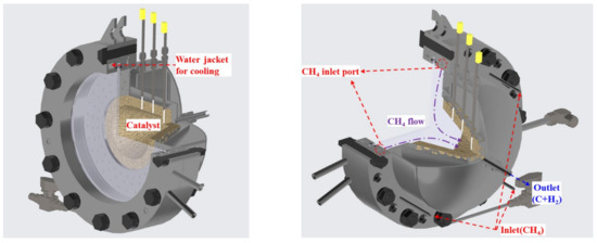
Figure 5.
Direct heating reactor model.
To determine the performance of the reactor, a preliminary experiment was performed after installing the reactor in the solar furnace, as shown in Figure 6. In the process of increasing the temperature, nitrogen was supplied, and 5 L/min of methane was supplied when the temperature of the structure reached 1000 °C. The decomposition of methane produced hydrogen and carbon, and some of the carbon in the product was deposited on quartz. As a result, the transmittance of the quartz decreased, and the concentrated light was locally absorbed, causing an increase in the temperature of the quartz, which subsequently resulted in a crack, as shown in Figure 7.
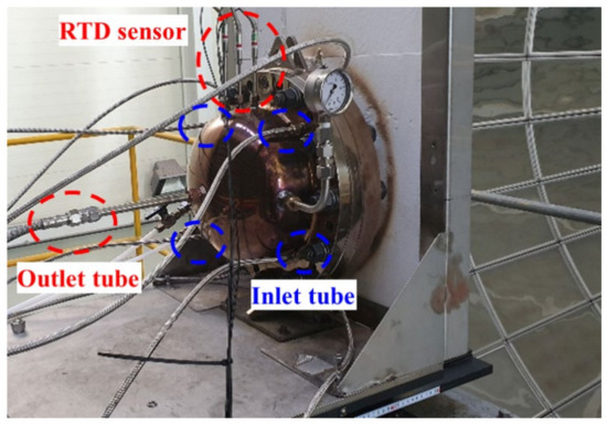
Figure 6.
Direct heating reactor with quartz window.
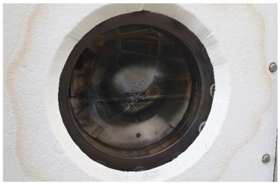
Figure 7.
Quartz window of reactor (after experiment).
One of the causes of this phenomenon is that the position of the methane injector, which is adjacent to the quartz, causes the carbon to become easily attached to the quartz. Accordingly, the inside of the reactor was modified to further increase the distance between the catalyst and the inlet port; however, the problem persisted. This was because some of the carbon produced did not exit smoothly through the outlet, and was accumulated inside the reactor, obstructing the flow from the inlet to the outlet. Another problem was that, as the gas supply flow increased, a gas leak occurred in the flange of the reactor, and it was difficult to prevent the leak owing to the weak stiffness of the quartz window.
4.2. Indirect Heating Reactor 1
To improve the quartz breakage and gas leakage in the reactor, a rotary cylindrical reactor was developed as shown in Figure 8, and its dimensions are shown in Table 1. The total length of the reactor was 400 mm, and a 315 mm catalyst was placed inside the reactor above the bottom cone. The upper end of the reactor was fastened with a flange to facilitate catalyst replacement, and a graphite seal was used between the flanges and the reactor to prevent gas leakage. When the concentrating position on one side of the reactor is fixed, rapid thermal damage may occur owing to continuous exposure. As a result, a motor and reducer were installed to supply a uniform heat flux in the circumferential direction, so that the reactor could be rotated. In addition, rotary joints serving as inlet and outlet were connected to the upper and lower ends of the reactor.
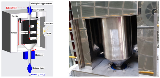
Figure 8.
Rotary cylindrical reactor 1 & cavity 1.

Table 1.
Rotary cylindrical reactor dimensions.
Inside the reactor, a catalyst coated with carbon black (CB I) on NiCrAl metal foam was installed to reduce the reaction temperature and activation energy required for methane decomposition [29]. The NiCrAl metal foam was dipped into the binder solution followed being mixed with powder. The powder-dipped metal foam was dried at room temperature overnight, and heat treated at 160 °C and 300 °C for 4 and 2 h, respectively, under static air. It is a circular catalyst with a diameter of 200 mm and thickness of 9.5 mm. Because the structure is metal, it has excellent conductivity, and can quickly transfer the amount of condensed heat supplied through the outer wall of the reactor to the inside of the reactor and the catalyst itself. Prior to the metal foam catalyst, a pellet catalyst was used, but heat transfer from the outer wall of the reactor to the center of the reactor was slow; hence, it took approximately 2 h for the catalyst temperature to reach 1000 °C. This could be shortened to approximately 1 h using a metal foam catalyst.
CB I contains oxygen functional groups on the surface, such as carbonyl, carboxyl, quinone, and epoxy. The improved coke resistance of carbon catalysts has been reported with the aid of oxygen functional groups [30]. Methane conversion using CB I-coated NiCrAl foam at different temperatures and gas hourly space velocity (GHSV) is shown in Figure 9. On the one hand, the methane conversion under 1000 °C rapidly decreased with the increase in GHSV. On the other hand, above 1100 °C, the methane conversion in various GHSVs was stable at 80%. These results show the characteristics of the catalyst used in this study, and indicate that a sufficient methane decomposition reaction takes place above 1000 °C, especially above 1100 °C.
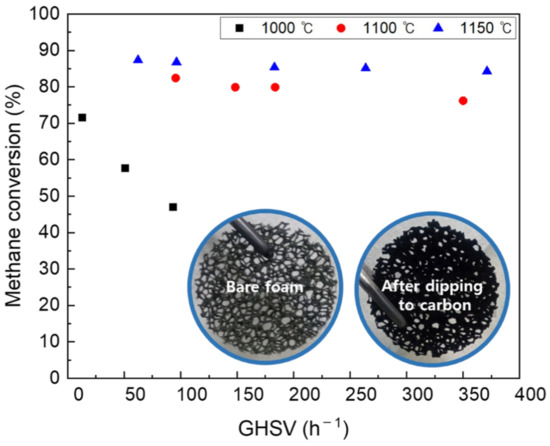
Figure 9.
Difference in catalyst activity according to GHSV by temperature.
In the experiment, a multiple temperature sensor was mounted along the rotation axis through the upper rotary joint, as shown in Figure 8, to measure the temperature of the catalyst center according to the height inside the reactor.
To reduce the heat loss of the reactor, a cavity filled with insulation material with a thickness of 50–100 mm was manufactured, and the reactor was positioned. The front of the cavity had an opening at the focal position to allow the concentrated light to pass through, and the diameter was initially 200 mm; however, to reduce the heat loss, the size of the concentrating area at the focal point was measured and reduced to be optimized at a diameter of 150 mm.
In a simple analysis, 40 L/min of methane is supplied to the reactor, and 1.7 kW is required to heat it to 1000 °C, and 2.75 kW is required to convert 80% of the methane to hydrogen during an endothermic reaction. In addition, the heat loss of 5.83 kW occurs. At the same time the cavity also heated up, and its radiation and convection heat were transferred to the environment in spite of the high insulation of the cavity. Thus, the effective solar light fraction used for heat and catalyzing the reaction of methane decomposition was approximately 83% and 27%, respectively.
4.3. Indirect Heating Reactor 2
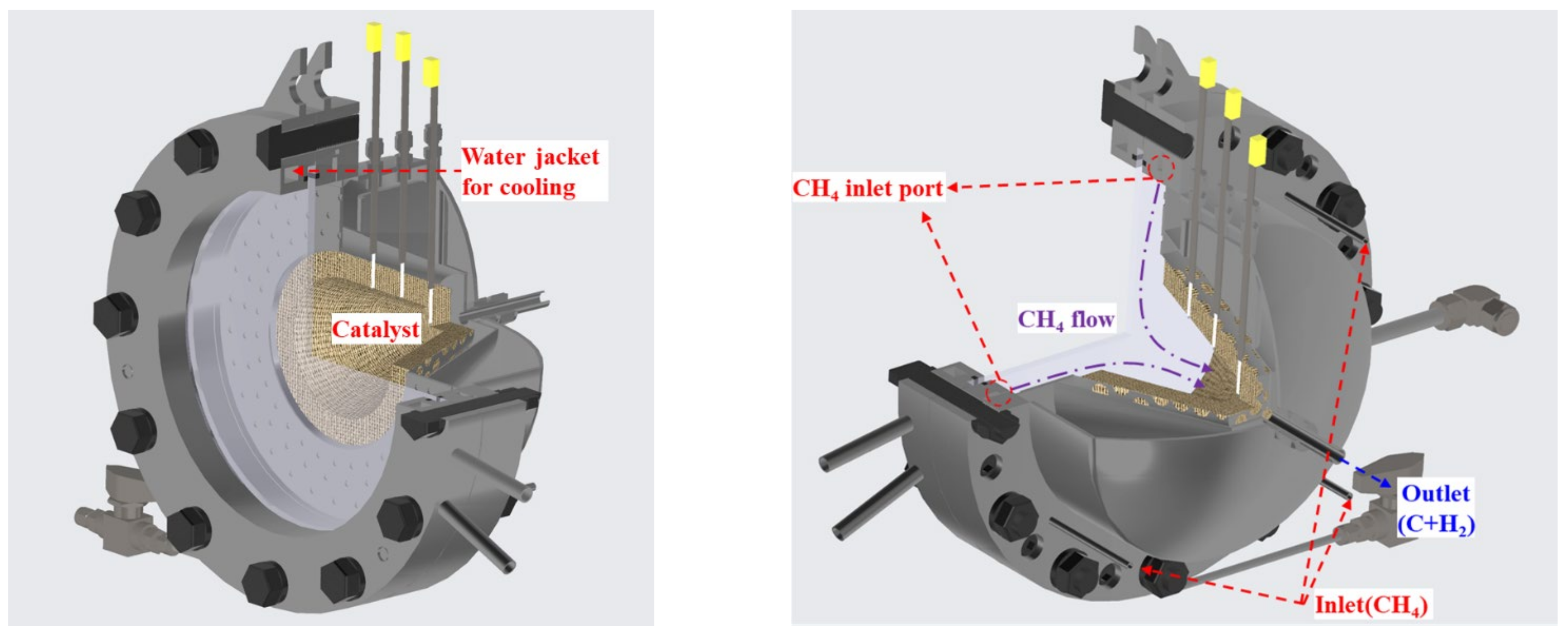
In indirect heating reactor 1, the temperature of the upper part of the catalyst was reduced by the methane flowing into the reactor, and the reaction volume above 1000 °C was also reduced, resulting in insufficient use of the catalyst volume. To increase the amount of catalyst involved in the reaction, the effective height of the reactor was increased from 315 to 400 mm, as shown in Figure 10. The amount of catalyst installed in the reactor and the volume of the reactor increased by approximately 27%, and flanges were attached to both the top and bottom of the reactor body to facilitate catalyst and reactor replacement.
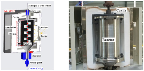
Figure 10.
Rotary cylindrical reactor 2 & cavity 2.
The existing cavity was improved to ensure that the amount of heat required for the reaction was achieved by reducing the radiant and convective heat loss of the reactor. By comparing the insulation material with the conventional hexahedral shape, which is similar to the shape of the reactor, the insulation material was found to have a close gap with the reactor.
Four Mosi2 heaters with a capacity of 2 kW were installed between the inside of the cavity and the rear of the reactor, in order to supply insufficient heat when the insolation fluctuated due to weather conditions, and to also increase the operating time through preheating before sunrise. The maximum amount of heat supplied was 8 kW, and the maximum operating temperature was 1400 °C; however, it could be increased by 5–10 °C per minute.
4.4. Indirect Heating Reactor 3
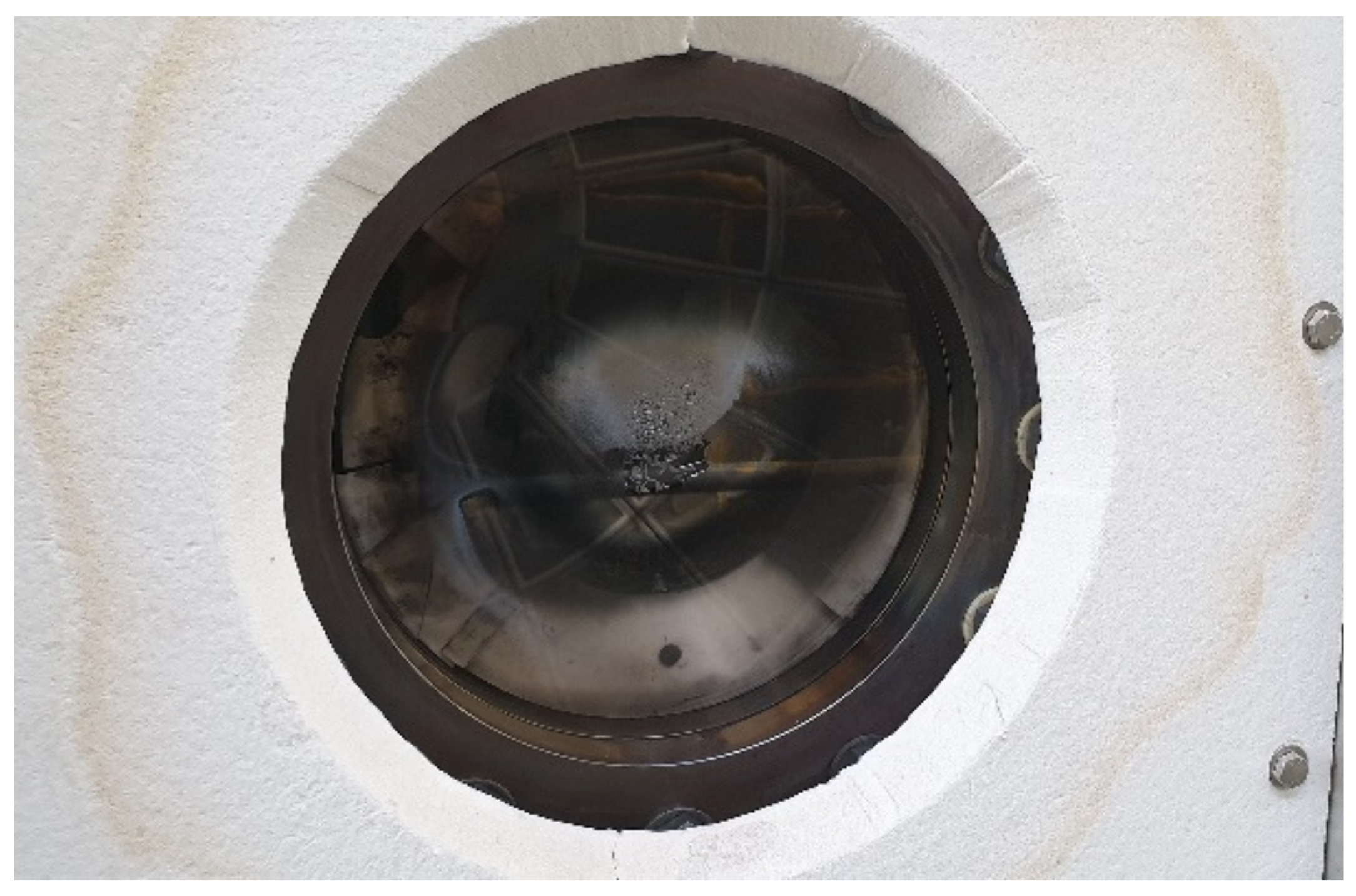
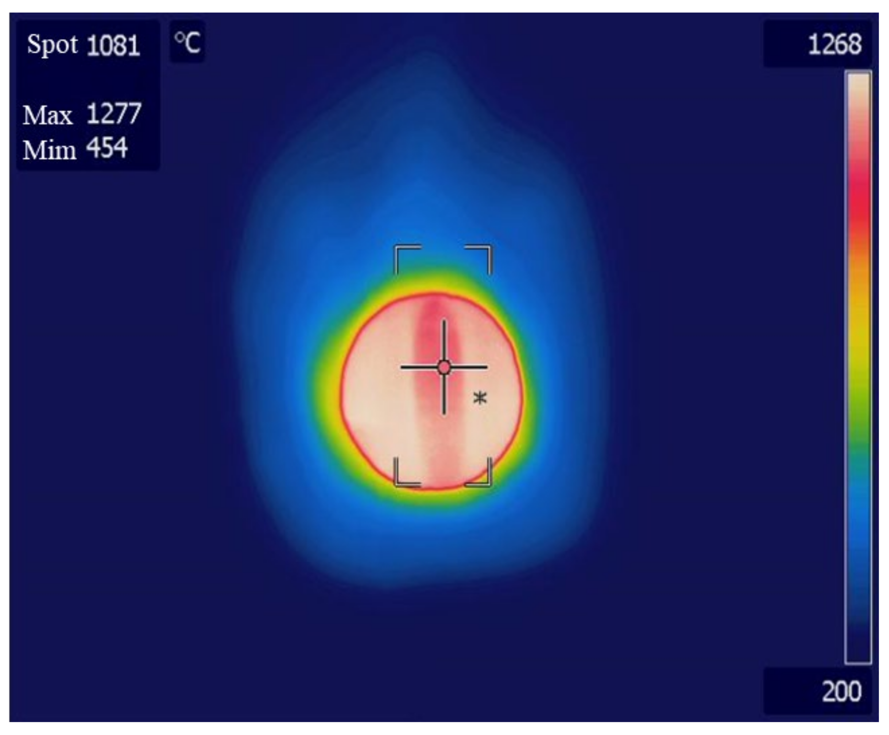
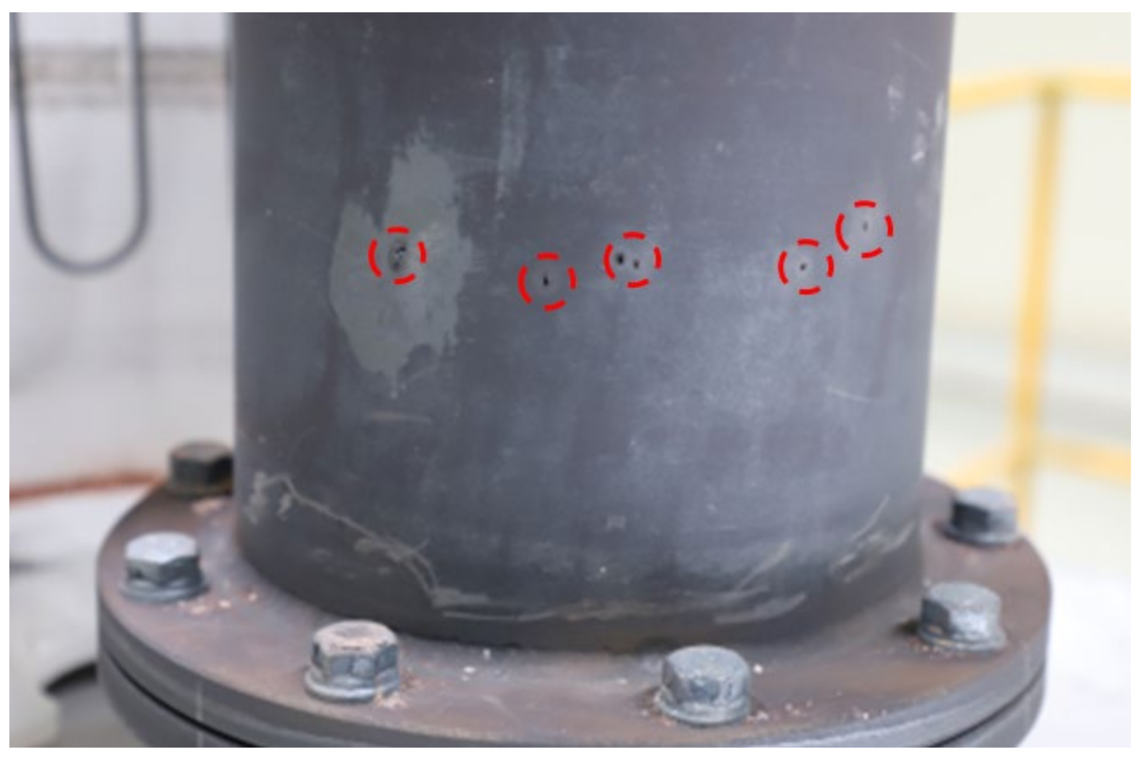
Experiments were performed using an improved reactor, as shown in Figure 10. When the temperature of the central part of the catalyst was 1000 °C, the surface of the reactor was measured using a thermal imaging camera, as shown in Figure 11. The reactor surface temperature was about 1300 °C, which is approximately 300 °C higher than the central part temperature of the catalyst, and since it is close to the melting point of SUS 310, the material of the reactor, deformation and melting may occur. In our experiments, the reactor surface was severed by gas leakage and flames. This is evident in Figure 12, where several holes and decreased surface thickness were found in the reactor.

Figure 11.
Reactor 2 surface temperature measured by thermal imaging camera.

Figure 12.
Damaged reactor 2 (after experiment).
Therefore, the thermal barrier coating used for gas turbine blades and aviation engines was applied to the reactor surface, as shown in Figure 13, to improve the durability of the reactor, and enable long-term experiments in a high temperature environment. The coating was a double layer, and consisted of a zirconia and bond layer with average thicknesses of 211 μm and 110.6 μm, respectively. Through thermal barrier coating, the temperature limit of the reactor material was increased by 100–200 °C, thereby improving the durability. In the past, methane was supplied through a single port in line with the rotation axis of the reactor, and 20 nozzles were positioned in the circumferential direction of the upper flange of the reactor, so that methane was uniformly supplied to the catalyst.
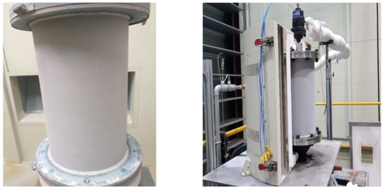
Figure 13.
Reactor 3 with thermal barrier coating.
Starting with the initial direct heating reactor, the reactor was improved step by step, as shown in Table 2. To solve the problem of carbon deposition on quartz in the direct heating reactor, an indirect heating reactor was developed (indirect 1). Afterwards, the reactor length was increased to expand the reaction volume and catalyst amount (indirect 2), the cavity shape was changed to reduce heat loss, and a thermal barrier coating was applied to improve durability (indirect 3).
Table 2.
Reactor development process.
5. Experimental Results
5.1. Indirect Heating Reactor 1
Figure 14 shows the experimental results using the indirect heating reactor 1 in Figure 8. The central and bottom parts of the catalyst reached the target temperature of 1000 °C relatively early, whereas the top part took approximately 40 min to reach the target temperature, because methane flowed into the top of the reactor. When the top catalyst temperature reached 1000 °C, 10 L/min of methane was supplied instead of nitrogen for approximately 50 min. Owing to the conversion to methane and increase in the flow rate, the temperature of the catalyst at the top of the reactor rapidly decreased by approximately 120 °C. While the catalyst temperature was stabilized at a methane flow rate of 10 L/min, three measurements were performed every 5 min, resulting in an average methane conversion rate of approximately 88.1%. Afterwards, the methane flow rate was increased to 20 L/min, and supplied for approximately 25 min. At this time, the temperature of the top catalyst was lowered to approximately 680 °C, and the central catalyst was lowered to 950 °C and subsequently fell below 1000 °C. Therefore, the average conversion rate, measured three times, also decreased to 66%. As a result of adjusting the methane flow rate to 15 L/min, the temperatures of the top and central catalysts increased by approximately 100 °C and 40 °C, respectively, and the conversion rate was measured to be 67%.
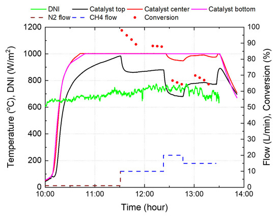
Figure 14.
Experimental results using the reactor 1.
5.2. Indirect Heating Reactor 2
For comparison with the reactor 1 experiment, the experiment was performed using the improved reactor 2 and cavity 2 in Figure 10, without the operation of the internal heater, and the results are shown in Figure 15.
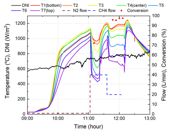
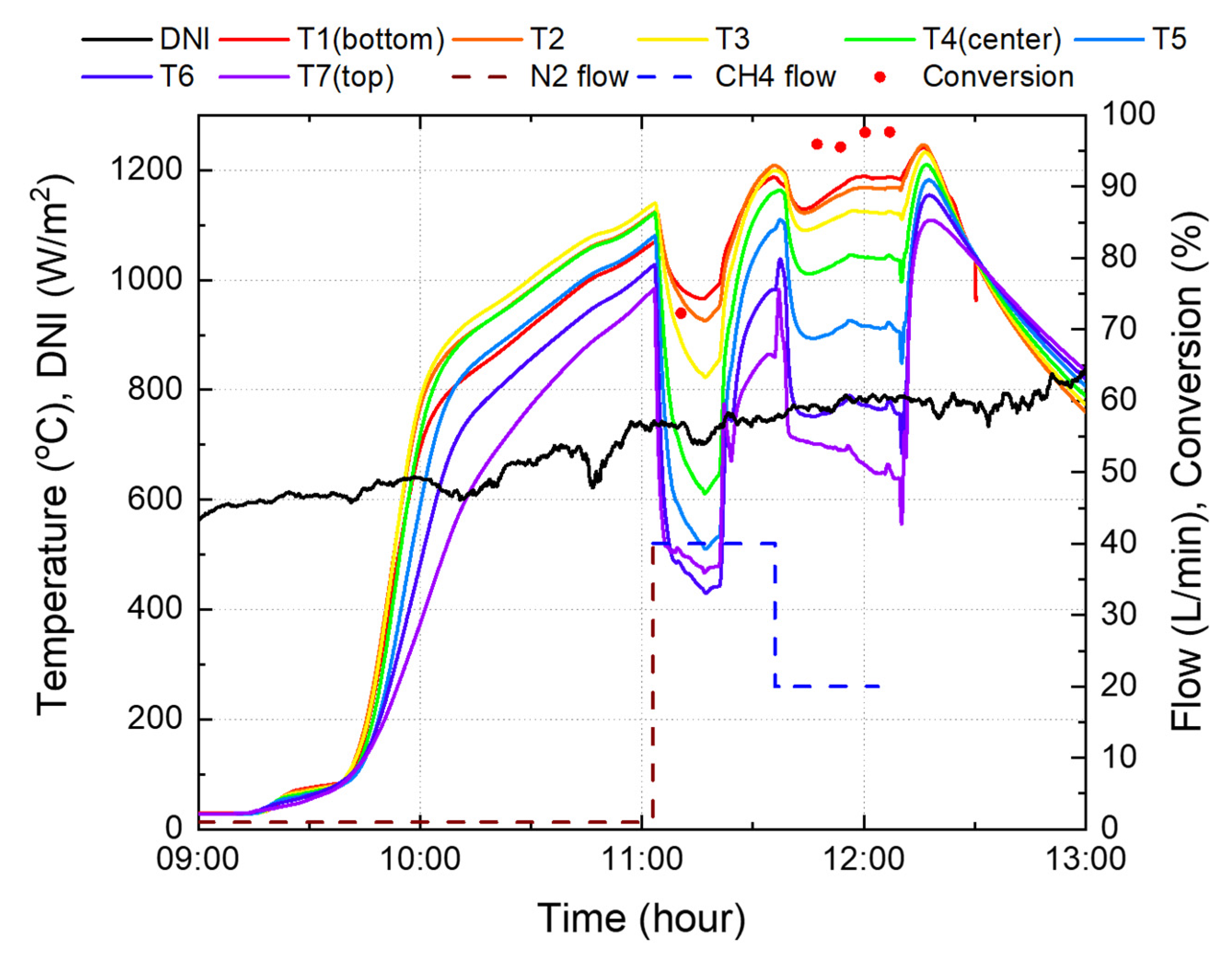
Figure 15.
Experimental results using the reactor 2.
After increasing the catalyst temperature, the methane flow rate was maintained at 40 L/min. Concurrently, the temperature of the top and central parts decreased by approximately 500 °C, while the bottom part decreased by approximately 100 °C. Owing to the large temperature drop, the experiment was conducted by reducing the methane flow rate to 20 L/min. Therefore, the catalyst temperature was maintained above 1000 °C, with the exception of the top part where methane, which was at room temperature, was in contact. Conversion rates were measured four times, and achieved an average of 96.7% when the average and maximum temperatures were 978 °C and 1189 °C, respectively. In the case of reactor 1 in Figure 14, when the methane flow rate was 20 L/min, the temperature of the catalyst in the central part was less than 1000 °C, indicating that the area utilized for the reaction was less than 50% of the total catalyst. Thus, the effective height of the activated catalyst was less than 157.5 mm. In the case of reactor 2, as shown in Figure 15, it can be confirmed that the catalyst temperature is over 1000 °C, with the exception of the area up to 150 mm (T5) above the catalyst. This is 63% of the total catalyst, and the effective height of the catalyst is 252 mm; therefore, reactor 2 is more effective in terms of reaction and methane conversion than the existing reactor 1.
When the methane flow rate was 20 L/min, the catalyst temperature at the bottom of reactor 2 was approximately 1200 °C, which is quite high and dangerous, since it is close to the limit temperature of the reactor material. Although it is recommended that the total catalyst temperature be kept high above 1000 °C, the highest temperature approached the maximum temperature limit of 1200 °C, and the amount of sunlight was reduced using blinds. Thus, it was found that the catalyst in the reactor was far lower than 1000 °C.
5.3. Indirect Heating Reactor 3
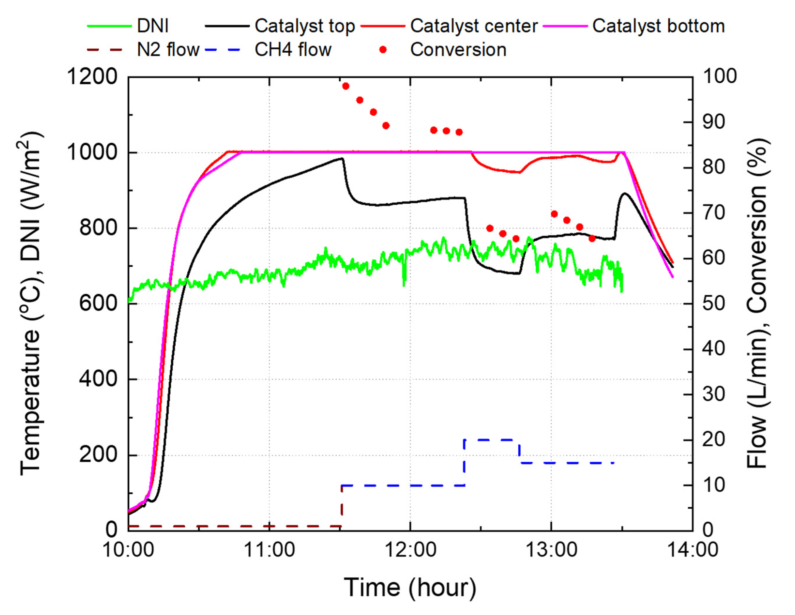
Figure 16 shows the experimental results for reactor 3 in Figure 13. To increase the reaction time, heating was started before sunrise using a heater inside the cavity. After sunrise, solar thermal energy was supplied together with the heater to the reactor. When the temperature at the center and bottom of the catalyst reached 1000 °C, 40 L/min of methane was supplied instead of nitrogen. Afterwards, the heater was used only to supply heat as a result of insufficient heat owing to fluctuations in insolation.
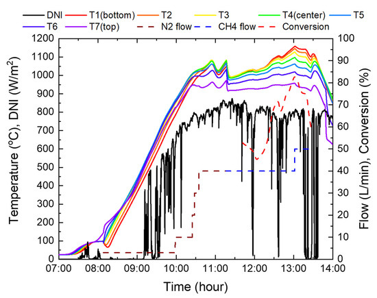
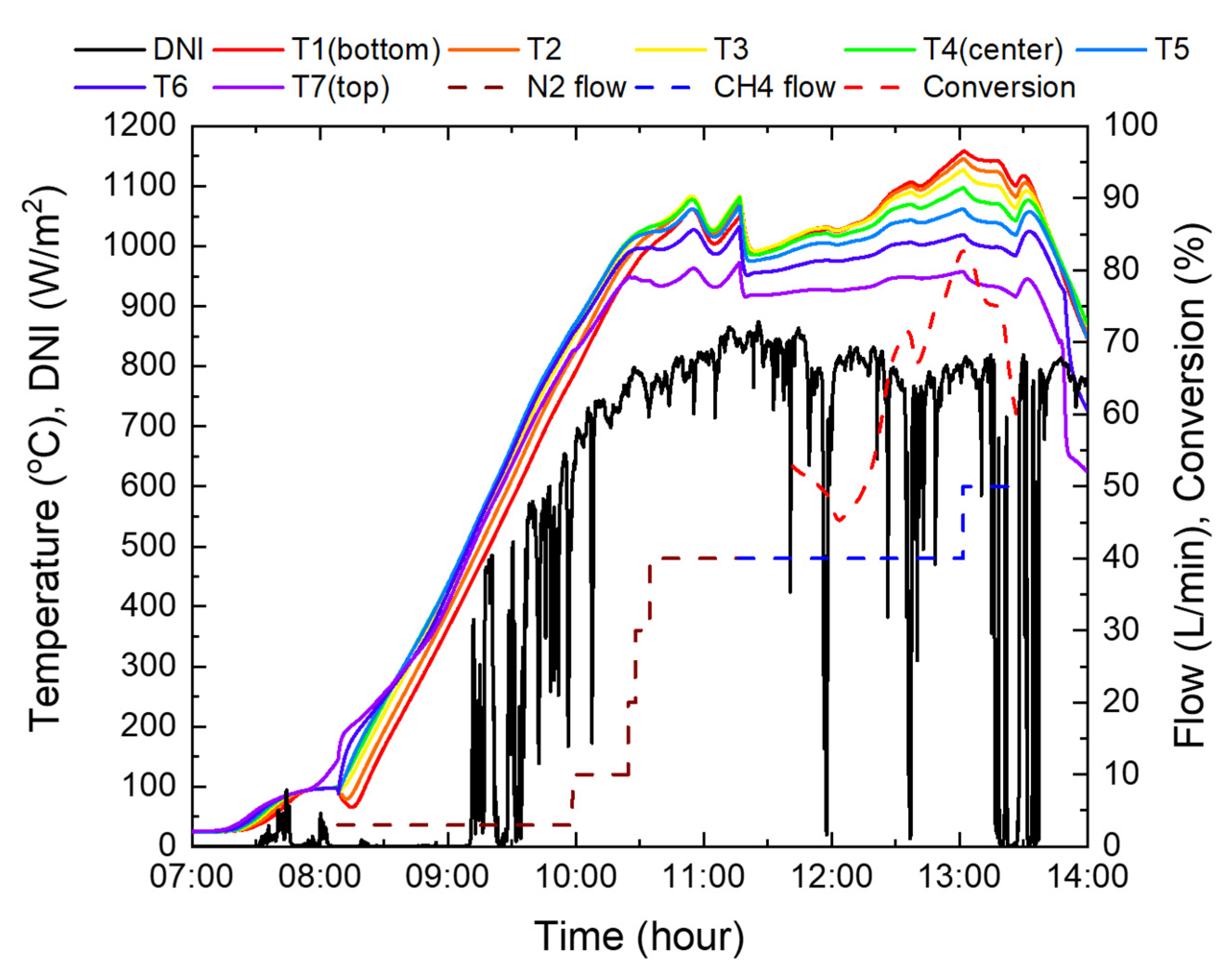
Figure 16.
Experimental results using the reactor 3.
At the beginning of the supply of methane, the catalyst temperature dropped by approximately 100 °C due to an endothermic reaction that occurs when methane is decomposed and the specific heat of methane is twice that of nitrogen. Accordingly, to increase the temperature, the blind opening ratio was increased from 60% to 90%. After 30 min of methane supply, it was confirmed that there was no nitrogen in the reactor system, and the conversion rate was measured using a gas analyzer. The initial conversion rate was in the range of 45–52%, as the entire catalyst temperature was lower than 1000 °C. However, as the catalyst temperature increased steadily to an average of 1081 °C, and a maximum of 1158 °C, a maximum conversion rate of 82.6% was achieved at 40 L/min of methane. Subsequently, to confirm the conversion rate at higher flow rates, it was increased to 50 L/min; however, the experiment was suspended due to cloudy weather. Furthermore, the sun’s altitude angle was lowered after the meridian transit time.
In Figure 16, at 40 L/min of methane, the conversion rate was 71.5% when the average temperature of the catalyst’s top, center, and bottom was 1041 °C, but increased to 82.6% at 1071 °C. This implies that when the temperature rises by 2.8% on average, the conversion rate increases by 11.1%, which shows that the conversion rate by catalyst activation has high temperature sensitivity.
Reactor 2 was used in the experiment for 4.5 h; however, reactor 3 with applied thermal barrier coating was used for approximately 50 h, which is estimated to be eleven times longer operation than that of Reactor 2. Therefore, it is established that thermal barrier coating increases the durability of the reactor. Nonetheless, increasing the catalyst temperature above 1200 °C may cause thermal damage to the reactor; hence, the catalyst temperature must be controlled during the experiment.
In addition, when the methane flow rate and conversion rate were 40 L/min and 82.6%, respectively, the system efficiency was calculated as in Equation (5), and 65.6% was achieved. Two servo motors with power consumption of 800 W and a 150 W control PC were driven for 2-axis control of the heliostat. The calorific value of hydrogen and methane is based on the lower heating value.
6. Comparison with Literature Results
A previous study on methane decomposition using solar heat, which was conducted in a 50 kW class indirect heating type reactor, is the most advanced research in the field of solar heat methane decomposition to date. A conversion rate of up to 98% was achieved at a methane flow rate of 21 L/min and temperature of 1525 °C by direct decomposition without a catalyst, as shown in Table 3 [24]. In comparison, this study obtained similar experimental results with an average conversion rate of 96.7% at a maximum catalyst temperature of approximately 1189 °C, which was estimated to be 336 °C lower than that of advanced research when the methane flow rate was 20 L/min in a 40 kW solar furnace. In addition, a conversion rate of 82.6% was achieved when the methane flow rate was 40 L/min.
Table 3.
Thermal amounts at the reactor surface according to the focal distance.
7. Conclusions
In this study, methane was decomposed using solar thermal energy, and a catalyst coated with carbon black on a metal foam was used to lower the temperature and activation energy required for the reaction, and also increase the conversion rate. For this purpose, a methane decomposition reactor suitable for solar thermal systems was developed. The use of direct heating reactors causes carbon particles to be deposited on the quartz surface, which results in gas leakage at high flow rates. To solve this problem, three indirect heating reactors were developed steadily. During the process, the reactor performance was improved by enhancing the reactor capacity, increasing the amount of catalyst, changing the cavity shape to reduce heat loss, and applying a heat barrier coating to improve durability at high temperatures.
Experiments were carried out at each stage of the reactor development, and conversion rates of 96.7% and 82.6% were achieved when the methane flow rates were 20 L/min and 40 L/min, respectively. Compared with the most advanced non-catalytic decomposition studies, this study obtained similar experimental results using catalysts at a maximum reaction temperature of 1189 °C.
For this study to be commercialized, it is necessary to minimize the deposition of the produced carbon on the catalyst, and to facilitate the capture of carbon and hydrogen. Additionally, the following aspects are required to achieve higher conversion rates of over 80% at increased flow rates: (i) expansion of solar heat capacity, (ii) enlargement of reactor and catalyst volume, (iii) development of catalysts activated at a lower temperature, and (iv) additional improvement and research on the development of high efficiency reactors.
Author Contributions
Conceptualization, H.K. (Haneol Kim) and J.K.; methodology, H.K. (Haneol Kim) and J.K.; validation, H.K. (Haneol Kim) and J.K.; formal analysis, H.K. (Haneol Kim) and J.K.; investigation, H.K. (Haneol Kim) and J.K.; resources, H.K. (Haneol Kim), S.K. and J.K.; data curation, H.K. (Haneol Kim), S.K. and J.K.; writing—original draft preparation, H.K. (Haneol Kim), S.K. and J.K.; writing—review and editing, H.K. (Haneol Kim), H.K. (Hakjoo Kim), S.K., S.L. and J.K.; visualization, H.K. (Haneol Kim) and J.K.; supervision, J.K. All authors have read and agreed to the published version of the manuscript.
Funding
This research received no external funding.
Institutional Review Board Statement
Not applicable.
Informed Consent Statement
Not applicable.
Acknowledgments
This work was financially supported by a Grant-in-Aid from the “Global Top Environment R&D Center for Reduction of Non-CO2 Greenhouse Gases”, funded by the Ministry of Environment of the Republic of Korea (Project No. 2017002410010) and conducted under the framework of the research and development program of the Korea Institute of Energy Research (C1-2409).
Data Availability Statement
Not applicable.
Acknowledgments
This work was conducted under framework of the research and development program of the Korea Institute of Energy Research (C1-2409).
Conflicts of Interest
The authors declare no conflict of interest.
References
- Abbas, H.F.; Wan Daud, W.M.A. Hydrogen production by methane decomposition: A review. Int. J. Hydrog. Energy 2010, 35, 1160–1190. [Google Scholar] [CrossRef]
- Zhang, J.; Li, X.; Chen, H.; Qi, M.; Zhang, G.; Hu, H.; Ma, X. Hydrogen production by catalytic methane decomposition: Carbon materials as catalysts or catalyst supports. Int. J. Hydrog. Energy 2017, 42, 19755–19775. [Google Scholar] [CrossRef]
- Muradov, N.; Smith, F.; Huang, C.; T-Raissi, A. Autothermal catalytic pyrolysis of methane as a new route to hydrogen production with reduced CO2 emissions. Catal. Today 2006, 116, 281–288. [Google Scholar] [CrossRef]
- Ozalp, N.; Kogan, A.; Epstein, M. Solar decomposition of fossil fuels as an option for sustainability. Int. J. Hydrog. Energy 2009, 34, 710–720. [Google Scholar] [CrossRef]
- Sheu, E.J.; Mokheimer, E.M.A.; Ghoniem, A.F. A review of solar methane reforming systems. Int. J. Hydrog. Energy 2015, 40, 12929–12955. [Google Scholar] [CrossRef] [Green Version]
- Alves, L.; Pereira, V.; Lagarteira, T.; Mendes, A. Catalytic methane decomposition to boost the energy transition: Scientific and technological advancements. Renew. Sustain. Energy Rev. 2021, 137, 110465. [Google Scholar] [CrossRef]
- Qian, J.X.; Chen, T.W.; Enakonda, L.R.; Liu, D.B.; Mignani, G.; Basset, J.M.; Zhou, L. Methane decomposition to produce COx-free hydrogen and nano-carbon over metal catalysts: A review. Int. J. Hydrog. Energy 2020, 45, 7981–8001. [Google Scholar] [CrossRef]
- Guil-Lopez, R.; Botas, J.A.; Fierro, J.L.G.; Serrano, D.P. Comparison of metal and carbon catalysts for hydrogen production by methane decomposition. Appl. Catal. A Gen. 2011, 396, 40–51. [Google Scholar] [CrossRef]
- Paxman, D.; Trottier, S.; Flynn, M.R.; Kostiuk, L.; Secanell, M. Experimental and numerical analysis of a methane thermal decomposition reactor. Int. J. Hydrog. Energy 2017, 42, 25166–25184. [Google Scholar] [CrossRef]
- Muradov, N. Thermocatalytic CO2-Free Production of Hydrogen from Hydrocarbon Fuels. In Proceedings of the 2000 U.S. DOE Hydrogen Program Review, San Ramon, CA, USA, 9–11 May 2000; pp. 70–97. [Google Scholar]
- Muradov, N.; Smith, F.; T-Raissi, A. Catalytic activity of carbons for methane decomposition reaction. Catal. Today 2005, 102–103, 225–233. [Google Scholar] [CrossRef]
- Suelves, I.; Pinilla, J.L.; Lázaro, M.J.; Moliner, R. Carbonaceous materials as catalysts for decomposition of methane. Chem. Eng. J. 2008, 140, 432–438. [Google Scholar] [CrossRef]
- Ashik, U.P.M.; Wan Daud, W.M.A.; Hayashi, J. ichiro A review on methane transformation to hydrogen and nanocarbon: Relevance of catalyst characteristics and experimental parameters on yield. Renew. Sustain. Energy Rev. 2017, 76, 743–767. [Google Scholar] [CrossRef]
- Abanades, S.; Flamant, G. Solar hydrogen production from the thermal splitting of methane in a high temperature solar chemical reactor. Sol. Energy 2006, 80, 1321–1332. [Google Scholar] [CrossRef]
- Abanades, S.; Flamant, G. Experimental study and modeling of a high-temperature solar chemical reactor for hydrogen production from methane cracking. Int. J. Hydrog. Energy 2007, 32, 1508–1515. [Google Scholar] [CrossRef]
- Abanades, S.; Flamant, G. Hydrogen production from solar thermal dissociation of methane in a high-temperature fluid-wall chemical reactor. Chem. Eng. Process. Process Intensif. 2008, 47, 490–498. [Google Scholar] [CrossRef]
- Maag, G.; Zanganeh, G.; Steinfeld, A. Solar thermal cracking of methane in a particle-flow reactor for the co-production of hydrogen and carbon. Int. J. Hydrog. Energy 2009, 34, 7676–7685. [Google Scholar] [CrossRef]
- Hirsch, D.; Steinfeld, A. Solar hydrogen production by thermal decomposition of natural gas using a vortex-flow reactor. Int. J. Hydrog. Energy 2004, 29, 47–55. [Google Scholar] [CrossRef]
- Ozalp, N.; Jayakrishna, D. CFD analysis on the influence of helical carving in a vortex flow solar reactor. Renew. Energy 2010, 35, 6248–6260. [Google Scholar] [CrossRef]
- Yeheskel, J.; Epstein, M. Thermolysis of methane in a solar reactor for mass-production of hydrogen and carbon nano-materials. Carbon N. Y. 2011, 49, 4695–4703. [Google Scholar] [CrossRef]
- Dahl, J.K.; Buechler, K.J.; Weimer, A.W.; Lewandowski, A.; Bingham, C. Solar-thermal dissociation of methane in a fluid-wall aerosol flow reactor. Int. J. Hydrog. Energy 2004, 29, 725–736. [Google Scholar] [CrossRef]
- Rodat, S.; Abanades, S.; Coulié, J.; Flamant, G. Kinetic modelling of methane decomposition in a tubular solar reactor. Chem. Eng. J. 2009, 146, 120–127. [Google Scholar] [CrossRef]
- Rodat, S.; Abanades, S.; Sans, J.L.; Flamant, G. Hydrogen production from solar thermal dissociation of natural gas: Development of a 10 kW solar chemical reactor prototype. Sol. Energy 2009, 83, 1599–1610. [Google Scholar] [CrossRef]
- Rodat, S.; Abanades, S.; Sans, J.L.; Flamant, G. A pilot-scale solar reactor for the production of hydrogen and carbon black from methane splitting. Int. J. Hydrog. Energy 2010, 35, 7748–7758. [Google Scholar] [CrossRef]
- Valdés-Parada, F.J.; Romero-Paredes, H.; Espinosa-Paredes, G. Numerical simulation of a tubular solar reactor for methane cracking. Int. J. Hydrog. Energy 2011, 36, 3354–3363. [Google Scholar] [CrossRef]
- Kim, H.; Kim, J. Numerical Study on Optics and Heat Transfer of Solar Reactor for Methane Thermal Decomposition. Energies 2021, 14, 6451. [Google Scholar] [CrossRef]
- Lee, H.; Chai, K.; Kim, J.; Lee, S.; Yoon, H.; Yu, C.; Kang, Y. Optical performance evaluation of a solar furnace by measuring the highly concentrated solar flux. Energy 2014, 66, 63–69. [Google Scholar] [CrossRef]
- Cho, H.S.; Kodama, T.; Gokon, N.; Kim, J.; Lee, S.; Kang, Y. Development and experimental study for hydrogen production from the thermochemical two-step water splitting cycles with a CeO2 coated new foam device design using solar furnace system. AIP Conf. Proc. 2017, 1850, 100003. [Google Scholar]
- Kim, S.E.; Jeong, S.K.; Park, K.T.; Lee, K.Y.; Kim, H.J. Effect of oxygen-containing functional groups in metal-free carbon catalysts on the decomposition of methane. Catal. Commun. 2021, 148, 106167. [Google Scholar] [CrossRef]
- Ovejero, G.; Sotelo, J.L.; Romero, M.D.; Rodríguez, A.; Ocaña, M.A.; Rodríguez, G.; García, J. Multiwalled carbon nanotubes for liquid-phase oxidation. Functionalization, characterization, and catalytic activity. Ind. Eng. Chem. Res. 2006, 45, 2206–2212. [Google Scholar] [CrossRef]


Publisher’s Note: MDPI stays neutral with regard to jurisdictional claims in published maps and institutional affiliations. |
© 2021 by the authors. Licensee MDPI, Basel, Switzerland. This article is an open access article distributed under the terms and conditions of the Creative Commons Attribution (CC BY) license (https://creativecommons.org/licenses/by/4.0/).