Article

Broadband Spectral Analysis Algorithm with High-Frequency Resolution for Elimination of Overlap Interference between Adjacent Channels

1
School of Electronic Engineering, Changzhou College of Information Technology, Changzhou 213164, China
2
Changzhou Industrial Internet Research Institute Co., Ltd., Changzhou 213164, China
3
College of Electronics and Information, Hangzhou Dianzi University, Hangzhou 310018, China
4
The National Astronomical Observatories, Chinese Academy of Sciences, Beijing 100101, China
5
Institute of RF-OE-ICs, Southeast University, Nanjing 210096, China
*
Author to whom correspondence should be addressed.
Appl. Sci. 2021, 11(21), 10262; https://doi.org/10.3390/app112110262
Submission received: 25 September 2021 / Revised: 22 October 2021 / Accepted: 26 October 2021 / Published: 1 November 2021
(This article belongs to the Special Issue Advance in Digital Signal Processing and Its Implementation)

Abstract

:
Spectral lines can be analysed to determine the physical properties of molecular clouds and the astrochemical processes in the formation area of massive stars. To improve the observation technology of radio astronomy, this paper proposes and compares two spectral analysis algorithms (improved weighted overlap-add (IWOLA) + FFT and IWOLA + weighted overlap-add (WOLA)). The proposed algorithms can obtain an ultra-high-frequency resolution for real-valued wideband signals, eliminate the signal overlapping interference between adjacent channels, substantially decrease the required hardware resources, especially multipliers, adders, and memory resources, and reduce the system design complexity. The IWOLA + FFT algorithm consists of an improved weighted overlap-add (IWOLA) filter bank, fast Fourier transform (FFT), a specific decimation for the output data from the IWOLA filter bank, and a selection for part of the output data from the FFT. The IWOLA + WOLA algorithm consists of the same modules as the IWOLA + FFT algorithm, with the second-stage FFT replaced by the modules of the weighted overlap-add (WOLA) filter bank and the accumulation for each sub-band. Based on an analysis of the underlying principles and characteristics of both algorithms, the IWOLA + FFT algorithm demonstrated a spectrum with a high frequency resolution and a comparable performance to an ultra-large-scale FFT, based on two smaller FFTs and a flexible architecture instead of a ultra-large-scale FFT. The IWOLA + WOLA algorithm contains the same function as the IWOLA + FFT algorithm and demonstrates a higher performance. The proposed algorithms eliminated the interference between the adjacent channels within the entire Nyquist frequency bandwidth. The simulation results verify the accuracy and spectral analysis performances of the proposed algorithms.

1. Introduction

The observation of spectral lines can be used to accurately study the physical properties of molecular clouds in the formation area of massive stars, e.g., the temperature, density, radiation field, and astrochemical processes [1,2,3,4,5]. Therefore, the observation of spectral lines is critical in radio astronomy. During radio-astronomical observations, digital backends are generally required to have a wide bandwidth and high-frequency resolution [6,7,8,9]. To trace smaller-scale structures and more detailed dynamic characteristics, spectral line observations with high-frequency resolutions are conducted to extract information from the target celestial bodies. A frequency resolution of several hertz or 1 Hz is required in numerous high-precision spectral line observations. For example, during the Zeeman effect observation, if a neutral HI is observed, the frequency shift generated by each micro-Gauss magnetic field is 2.8 Hz. This requires a digital backend with a frequency resolution that should be higher than 2.8 Hz [10]. In addition, when observing the spectral lines, especially in the high-frequency band, the broadband receivers can simultaneously receive more information to improve the observation efficiency.
The requirements of the wideband and high-frequency resolution make it difficult to obtain the digital backends for radio-astronomical observations. At present, most signal processing techniques in the digital backends, such as spectral analysis, are implemented with a field programmable gate array (FPGA). Alternatively, according to the task requirements, signal pre-processing is first achieved in the FPGA, and further processing is performed by a computer with graphics processing units [11,12,13]. The maximum number of points of the available fast Fourier transform (FFT) intellectual property (IP) cores in the FPGAs used for the spectral analysis is 65536. If a resolution of 1 Hz is required for a signal with a 1 MHz bandwidth, a 106-point plain FFT is required, which necessitates a specialized design with a significant workload. The operating frequency of an actual FPGA is generally several hundred MHz. This indicates that a signal with an ultra-wide bandwidth greater than several hundred MHz cannot be directly processed by a simple FFT implemented on FPGA. Therefore, the direct application of a large FFT IP core in an FPGA to the ultra-large-scale FFT processing of wideband signals cannot be achieved to obtain an ultra-high-frequency resolution. Two methods are mainly used in radio astronomy to achieve this objective. A potential method involves the use of two-stage FFTs [14]. A commonly used method involves the combination of a polyphase filter bank (PFB) (sometimes called a WOLA filter bank) and an FFT or cascaded PFB structure [15,16,17,18,19,20]. For example, the combination regime is used as a spectrum analyser for the search for extra-terrestrial intelligence (SETI). It has a frequency resolution of 91 kHz when the processing bandwidth is 1.5 GHz, and a maximum frequency of 1 Hz when the processing bandwidth is 150 MHz [7,19,21]. In comparison with the two-stage FFT method, the aforementioned combined structure improves the frequency response characteristics for the first-stage channelised processing and the computational efficiency. This paper proposes a modified combination of the PFB + FFT to obtain improved flexibility with a more simplified design, and to conserve hardware resources in the FPGA. In addition, this paper proposes a IWOLA + WOLA algorithm to demonstrate an improved performance.
In this paper, a spectral analysis algorithm with an ultra-high-frequency resolution is first proposed for broadband real-valued signals. This algorithm uses an improved WOLA (IWOLA) [22] channelised filter bank to channelise the broadband signals preliminarily, and decimates the output data from the IWOLA filter bank appropriately. The IWOLA algorithm applies an equivalent Hilbert transform to the normal WOLA filter bank by shifting the centre frequency of every sub-band by half of the frequency bin, such that the IWOLA filter bank provides K/2 independently output complex sub-bands for real-valued signals instead of the general K/2 + 1 sub-bands, thus reducing the subsequent processing units by one set. After the decimation, FFT processing for the decimated data is carried out to perform spectral analysis with an ultra-high-frequency resolution. Furthermore, by selecting only a portion of the output data from the FFT, the interference between the adjacent channels can be eliminated within the entire Nyquist frequency bandwidth. To obtain a higher channelised performance, an optimized algorithm is finally proposed, which uses the IWOLA filter bank and the second-stage WOLA filter bank, instead of the second-stage FFT.
The remainder of this paper is organised as follows. In Section 2, the underlying principle and architecture of the proposed IWOLA + FFT algorithm are presented. In Section 3, the characteristics of the IWOLA filter bank and IWOLA + FFT algorithms are detailed, including the channelisation characteristics, spectra performance, and elimination of the overlapping interference between the adjacent channels. To improve performance of the IWOLA + FFT algorithm, the IWOLA + WOLA algorithm is proposed, and its performance analysis results are presented in Section 4. The simulation of the proposed algorithms and analysis results are presented in Section 5, followed by the conclusions in Section 6.

2. Basic Algorithm Principle

The WOLA algorithm was originally used in the short-time Fourier transform (STFT) [23], and the WOLA filter bank has been widely used in many fields such as sub-band coding, audio processing, and radio astronomy [24,25,26,27]. The output of the WOLA filter bank involves real- and complex-valued signals, and the number of the independent output sub-channels is K/2 + 1 (where K is the number of sub-bands); thus, the processing complexity and consumption of hardware resources is increased. To simplify the hardware implementation of the algorithm, the IWOLA algorithm [22] was proposed, which shifts the centre frequencies of every sub-band of the WOLA filter bank by π/K along the positive frequency axis. In particular, the expression of the IWOLA filter bank is as follows:
y ( υ , k ) = e j π ( 2 k + 1 ) υ D / K p = 0 K 1 F υ ( p ) e j 2 π k p / K ,
where
R v ( p ) = l = 0 D 1 ( 1 ) l x ( v D + l K + p ) w ( l K p ) ,
F v ( p ) = R v ( p ) e j π p / K ,
where l is an arbitrary integer that ranges from 0–D-1; k denotes the channel number; D denotes the decimation factor; p = 0 , 1 , 2 , , K 1 ; and w is a window function with coefficients that can be obtained by the design command fir1 in MATLAB for a finite impulse response (FIR) low-pass filter. The cut-off frequency of the FIR low-pass filter is fs/2/K.
This process of shifting frequency is equivalent to a Hilbert transform applied to the WOLA filter bank, thus causing all independent output sub-channels to exhibit identical features. The identities of the sub-bands of the IWOLA filter bank provide simplification for the hardware implementation of the processing. Furthermore, for a real-valued input signal, the output data from the K/2 + 1 sub-channels of the WOLA filter bank should be stored and processed further, whereas the output data from the K/2 sub-channels of the IWOLA filter bank should be stored and processed further. This reduces the amount of data processing and conserves off-chip memory resources, especially for a large second-stage FFT.
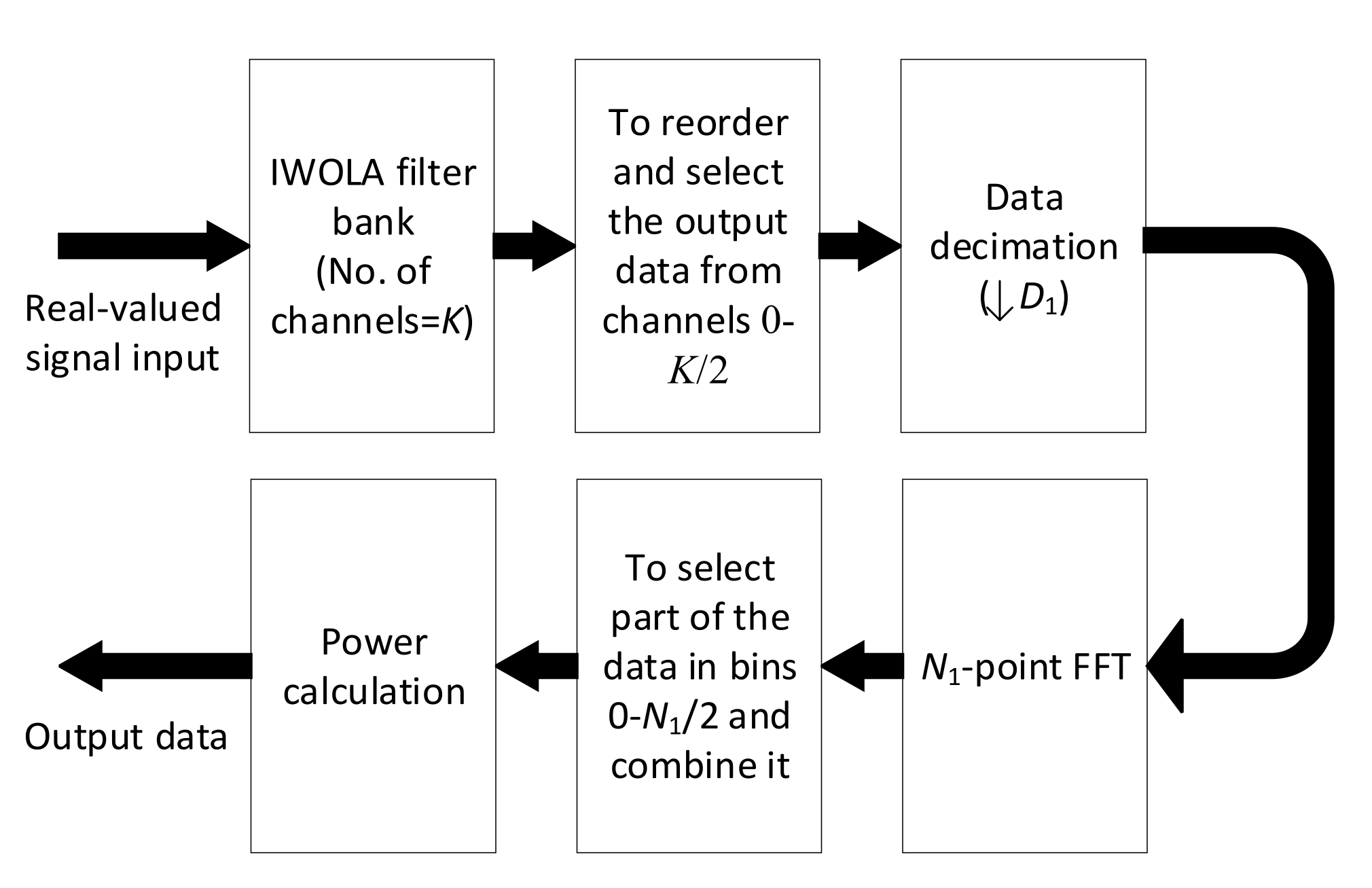
The overall framework of the spectral analysis algorithm based on the combined IWOLA + FFT structure is shown in Figure 1.
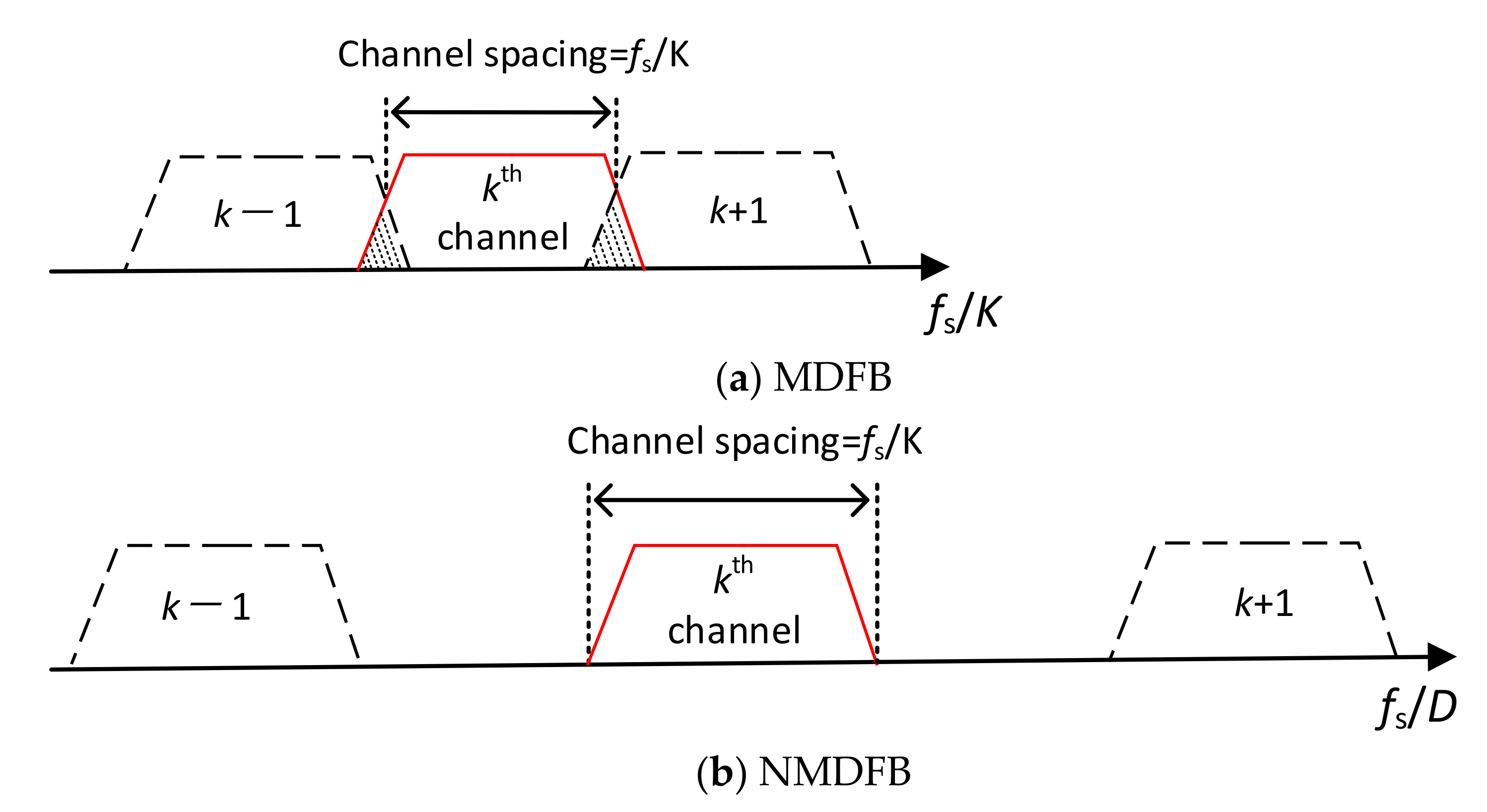
The output data of Sub-bands 0–K/2–1 of the IWOLA filter bank are transposed and obtained in-turn as outputs. If K = D, a maximally decimated filter bank (MDFB) [28] is produced, which has a relatively simple design and consumes less hardware resources. However, it leads to an aliasing effect (overlapping interference), as shown in Figure 2a. To avoid the aliasing effect, DK/2 is required, which results in a non-maximally decimated filter bank (NMDFB), as shown in Figure 2b. Generally, for a moderately large value of K, D is set as K/2. However, when K is significantly large, e.g., K = 220, D = 219. This leads to a low-pass filter prototype w with an order of magnitude of 239, which consumes a significantly large amount of hardware resources. In this case, assuming that D < K/2 (e.g., K = 220 and D = 218 or smaller), the maximum order number of the low-pass filter prototype is 238, which conserves half of the hardware resources, especially the multipliers and adders, at the expense of a slight performance reduction (slight decrease in the stopband attenuation). Under the condition of D < K/2, the data rate of each sub-band of the IWOLA filter bank is larger than the bandwidth value of each sub-band. Thus, if an FFT is implemented directly after the IWOLA filter bank, a large amount of computing resources are wasted. Therefore, before the FFT process, the data of each sub-band of the IWOLA filter bank should be decimated by a factor D1, as shown in Figure 1. The decimation factor D1 can be expressed as follows:
D 1 = K / 2 D
To make the decimating factor D1 a positive integer, D < K/2 and K is divisible by D. After the decimation by D1, the data rate of each sub-band decreases to a value twice its bandwidth, which is critical for solving the problem of interference from the neighbouring sub-channels. This leads to the maximal conservation of the computing resources, given that two moderate FFTs are used instead of an ultra-large FFT. The overlapping interferences between the adjacent sub-bands can be eliminated by appropriately selecting part of the output data from the N1-point FFT.
After the application of N1-point FFT to the decimated data of Sub-bands 0–K/2, the resulting frequency resolution df for each sub-band can be expressed as follows:
d f = f s / D / D 1 / N 1 = 2 f s / K / N 1
To eliminate the interference between the adjacent sub-bands, a part of the FFT bins of each sub-band is selected for the bin combination. The method of bin selection and the combination is shown in Table 1. The number of selected FFT bins N2 for Sub-bands 0–K/2–1 can be expressed as follows:
N 2 = f s / K / ( f s / D / D 1 / N 1 ) = D × D 1 × N 1 / K
It is necessary for N2 to be an integer, which can be readily obtained. Sub-bands 0–K/2–1 are all complex signals, which represent the entire frequency range of real-valued signals.
As shown in Table 1, the bins from 0–N2/2–1 and N1N2/2 to N1–1 are selected separately from the N1 FFT bins for each of the sub-bands from 0–K/2–1. The selected bins N1-N2/2 to N1-1 from each of the sub-bands from 0–K/2–1, respectively, are reversed and re-ordered. The selected bins in Sub-bands 0–K/2–1 are combined into one group along the order of the channel numbering. This represents the frequency-domain data for the real-valued signals within fs/2, and the signal power can then be calculated.
Based on the analysis presented above, the algorithm splits an ultra-large-scale FFT into a two-stage process, in which two smaller-scale FFTs are required. The N-point FFT requires a magnitude order of O(Nlog2N) operations. Therefore, if spectral processing with an ultra-high-frequency resolution (N is extremely large) is implemented in the FPGA, the algorithm reduces the operations to the magnitude order of O(Klog2K) + O(N1log2N1) (K and N1 << N). This conserves hardware resources and compensates for the lack of a commercially available enormous point FFT IP core.
As mentioned before, the WOLA filter bank is equivalent to the PFB. They are both efficient implementation of the channelization processing. Therefore, their computational and hardware complexity is equivalent. In comparison with the expressions of the IWOLA filter bank and the WOLA filter bank [22], the expression of the IWOLA filter bank involves two terms more: (−1)l and e-jπp/K. It is obvious that the first term does not increase the computational and hardware complexity; the second term only necessitates one complex multiplication operation and two block RAMs (BRAMs) in the FPGA. The capacity of the two extral BRAMs is K × 16 bit, given that each data of the second term is expressed with 16 bits in the FPGA. The function of the data decimation is to select or discard data, which does not increase the computational and hardware complexity.

3. Analysis of the IWOLA + FFT Algorithm Characteristics

3.1. Subsection

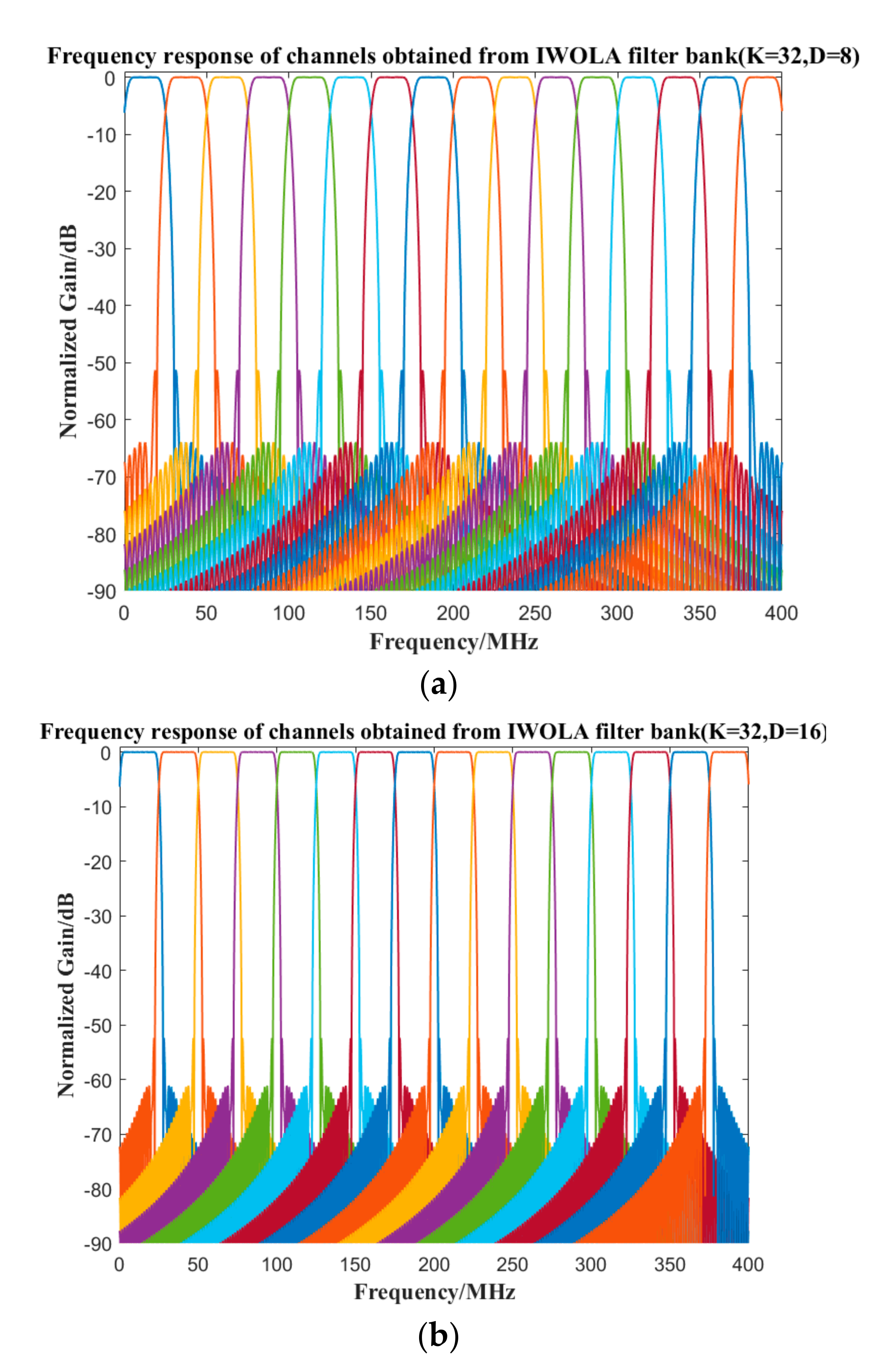
The channel characteristics of the IWOLA filter bank can be designed based on the task requirements. By selecting different values of the decimating factor D of the IWOLA filter bank, the channel frequency responses of the IWOLA filter bank with different performances can be obtained, as shown in Figure 3. To simplify the description, K and D were set as small values. When D = 16, the overlap between the adjacent channels was significantly less than D = 8, and the pass-band gain in the sub-bands was flatter than that in the case of D = 8. Therefore, the performance of the IWOLA filter bank was improved with an increase in D. However, it required more hardware resources. During the actual applications, the designs can be traded off according to specific needs.
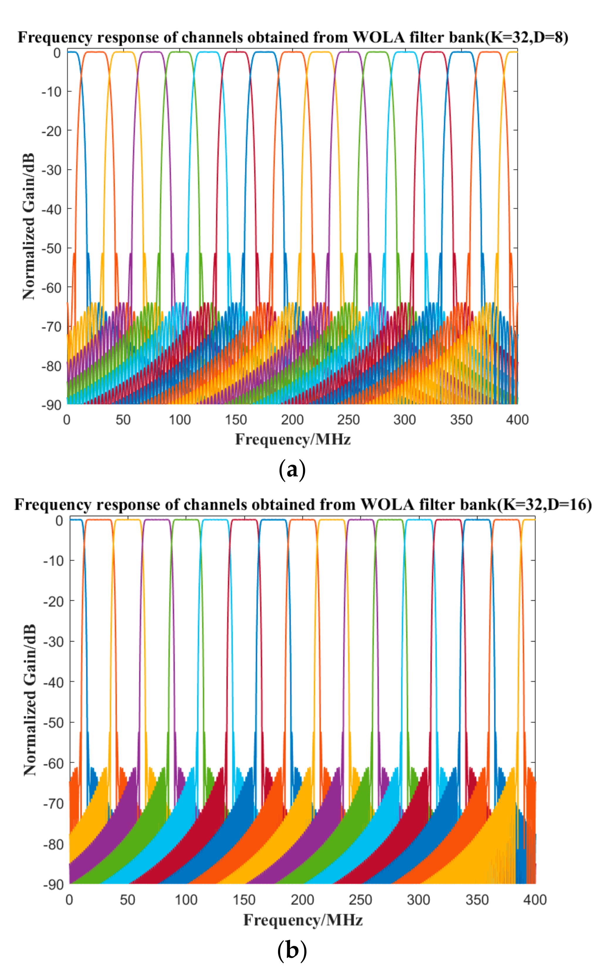
Under the same conditions as the IWOLA filter bank, the frequency responses of the WOLA filter bank are presented in Figure 4. The frequency response for D = 16 was superior to that for D = 8, given that the former exhibited a flatter channel gain and narrower overlaps between neighbouring sub-channels. However, more hardware resources were consumed. In comparison, the frequency response characteristic of the IWOLA filter bank was identical to that of the WOLA filter bank, with the exception of shift in the centre frequency of each sub-band by π/K.

3.2. Elimination of the Overlap Interference between the Adjacent Subchannels

After the decimation by D1, the output data rate for each subchannel in the IWOLA filter bank was twice the value of the subchannel bandwidth. Therefore, after the N1-point FFT, only the FFT bins that correspond to the actual frequency of each sub-band should be selected. Figure 5 presents the actual bandwidth and sampling frequency of each sub-band after the decimation. The actual sampling frequency of each sub-channel fs1 was equal to fs/(D × D1). The shaded parts represent the actual bandwidth B of each sub-band, f2 is the cut-off frequency of the frequency response characteristic of the aforementioned window function, and f1 is a mirror frequency of f2 relative to fs1/2. The number of selected bins for Sub-bands 0–K/2–1 N2 was obtained from (6), B = 2 × f2 = N2 × df, instead of fs1, and f1 = fs1f2. For Sub-bands 0–K/2–1, their signals were complex. Therefore, it was necessary to select N2 N1-FFT bins, in which N2/2 N1-FFT bins, which were numbered from zero to the point corresponding to f2, were sequentially selected; and the other N2/2 bins were sequentially selected from the point corresponding to f1 to the point corresponding to fs1. Thereafter, a combination of the two parts of the bins can only cover the bandwidth of the complex signals in Sub-bands 0–K/2–1.
Throughout the process of the proposed algorithm, the part of the N1-point FFT bins that does not correspond to the actual bandwidth of each sub-band is discarded. This eliminates the signal overlap interference between the adjacent sub-bands. Moreover, the decimation of D1 reduces the operating frequency for further processing; thus ensuring the utilization of the computing resources.

3.3. Performance Comparison of the IWOLA + FFT Algorithm with a Direct FFT

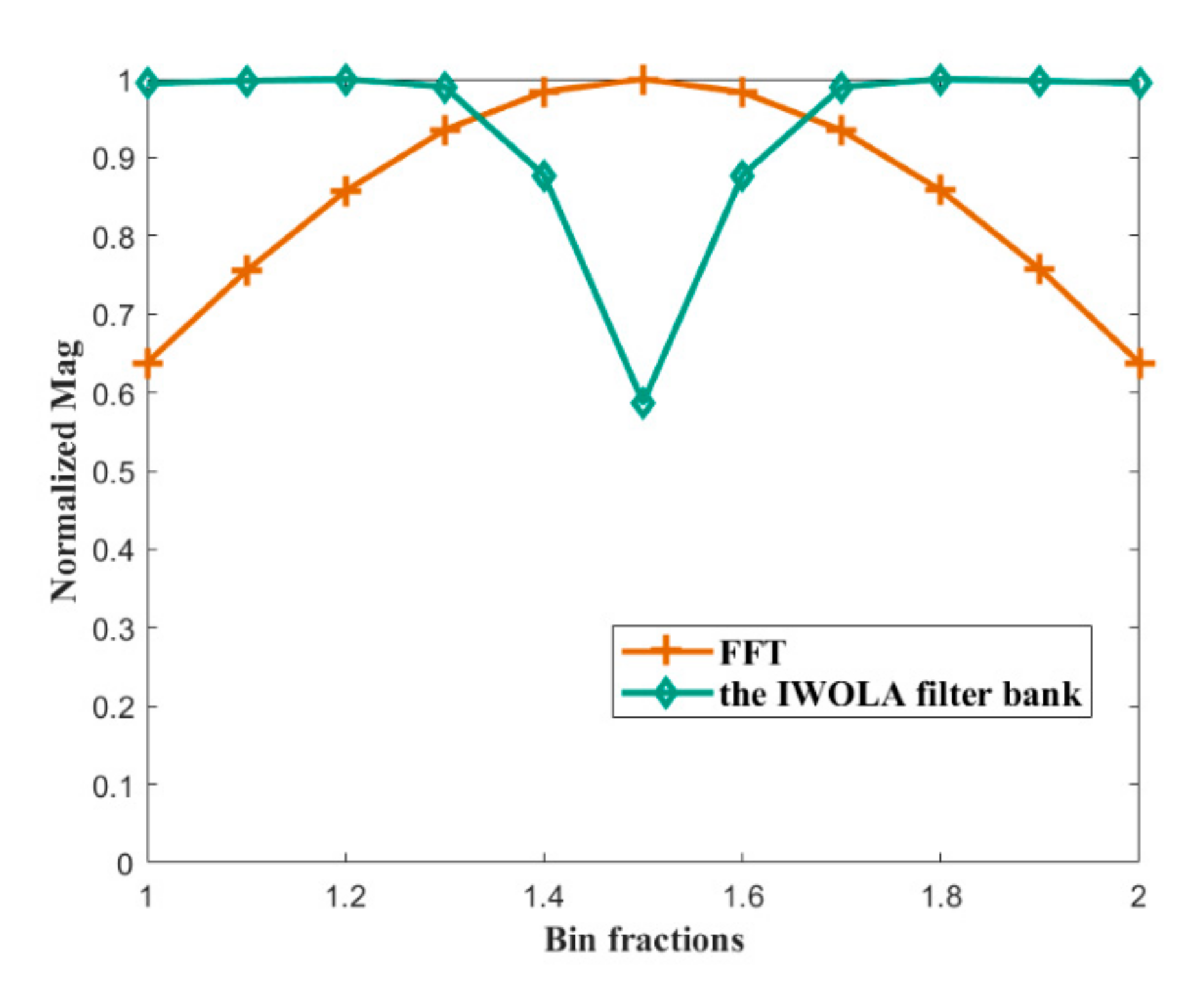
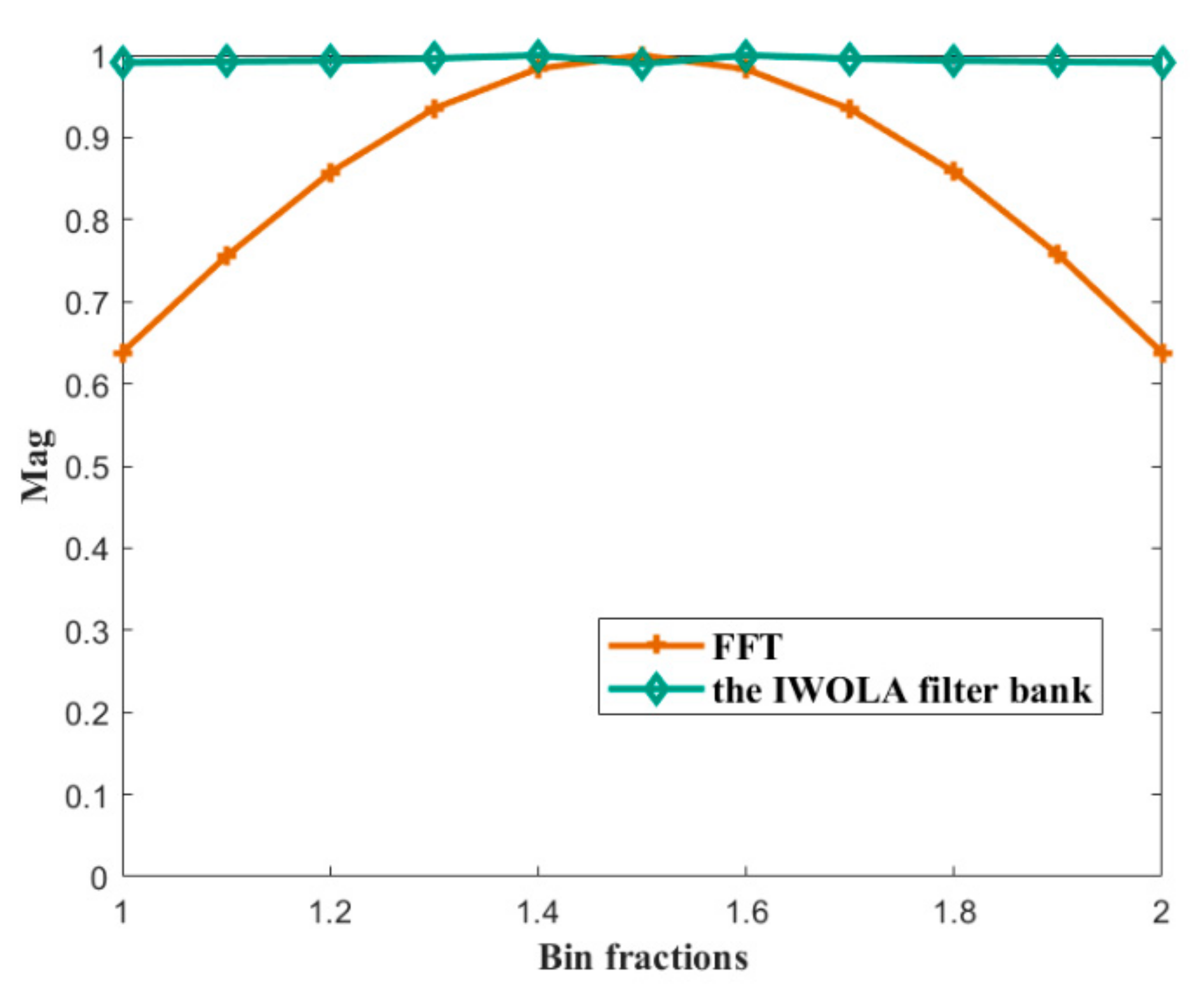
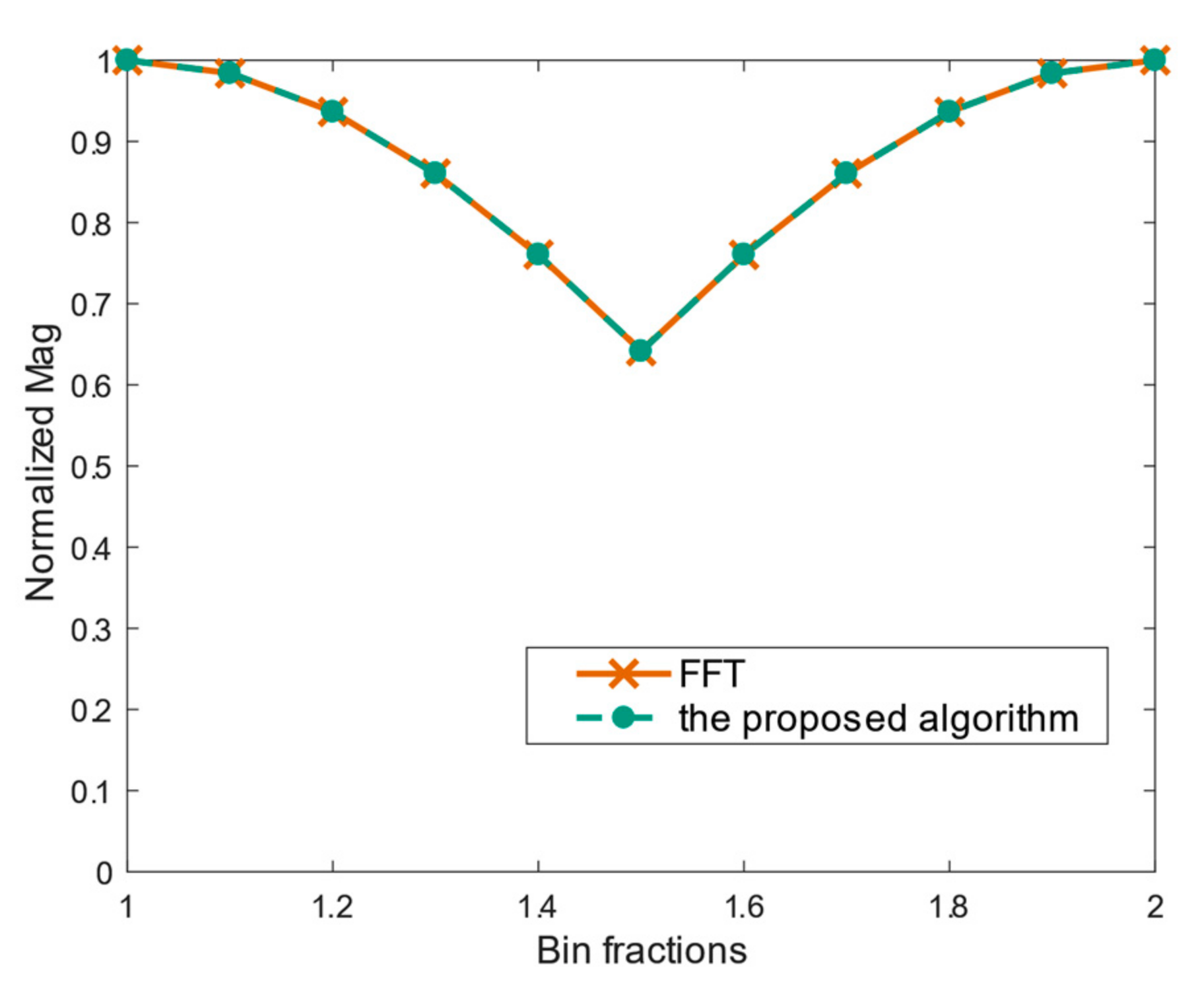
An assessment of the scalloping losses of the IWOLA filter bank, proposed algorithm, and direct FFT is presented below. First, we compared the scalloping loss of the IWOLA filter bank with that of the direct FFT by sweeping the frequency domain with 11 sinusoidal signals from one bin centre (e.g., the first bin) to an adjacent bin centre (the second bin). Thereafter, the maximum magnitude was plotted as shown in Figure 6. The analysis results revealed that the IWOLA filter bank exhibited a gain depression of approximately 0.36 near the border of the adjacent sub-channels. The adverse influence on the IWOLA + FFT algorithm is detailed further in this manuscript, and can be minimized by changing the characteristics of the window function for the IWOLA filter bank. We scanned the frequency characteristics from one bin centre to an adjacent bin centre using 11 sinusoidal signals. The improved result is plotted in Figure 7, which indicates a flatter gain curve of the IWOLA filter bank. This implies that the gain loss problem caused by channelisation was solved, and the scalloping loss of the IWOLA + FFT structure only depends on the succeeding FFT. Furthermore, under the assumption that the frequency resolution of the IWOLA + FFT algorithm is the same as that of the direct FFT, we analysed the scalloping losses using a similar approach to Figure 6. We then plotted the normalized magnitude, as shown in Figure 8. As can be seen from the figure, the proposed algorithm demonstrated the same scalloping loss characteristics as the direct FFT.
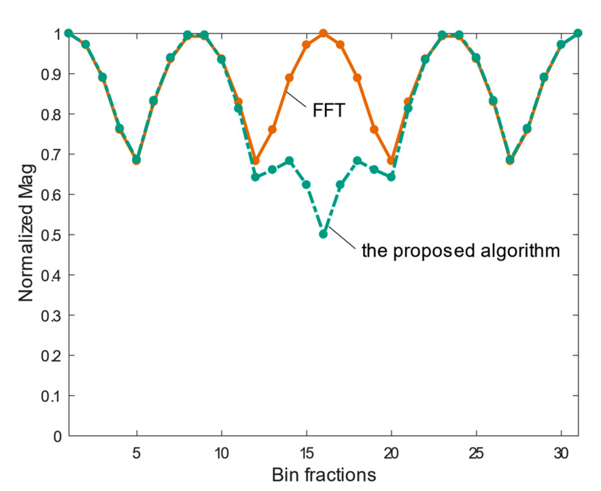
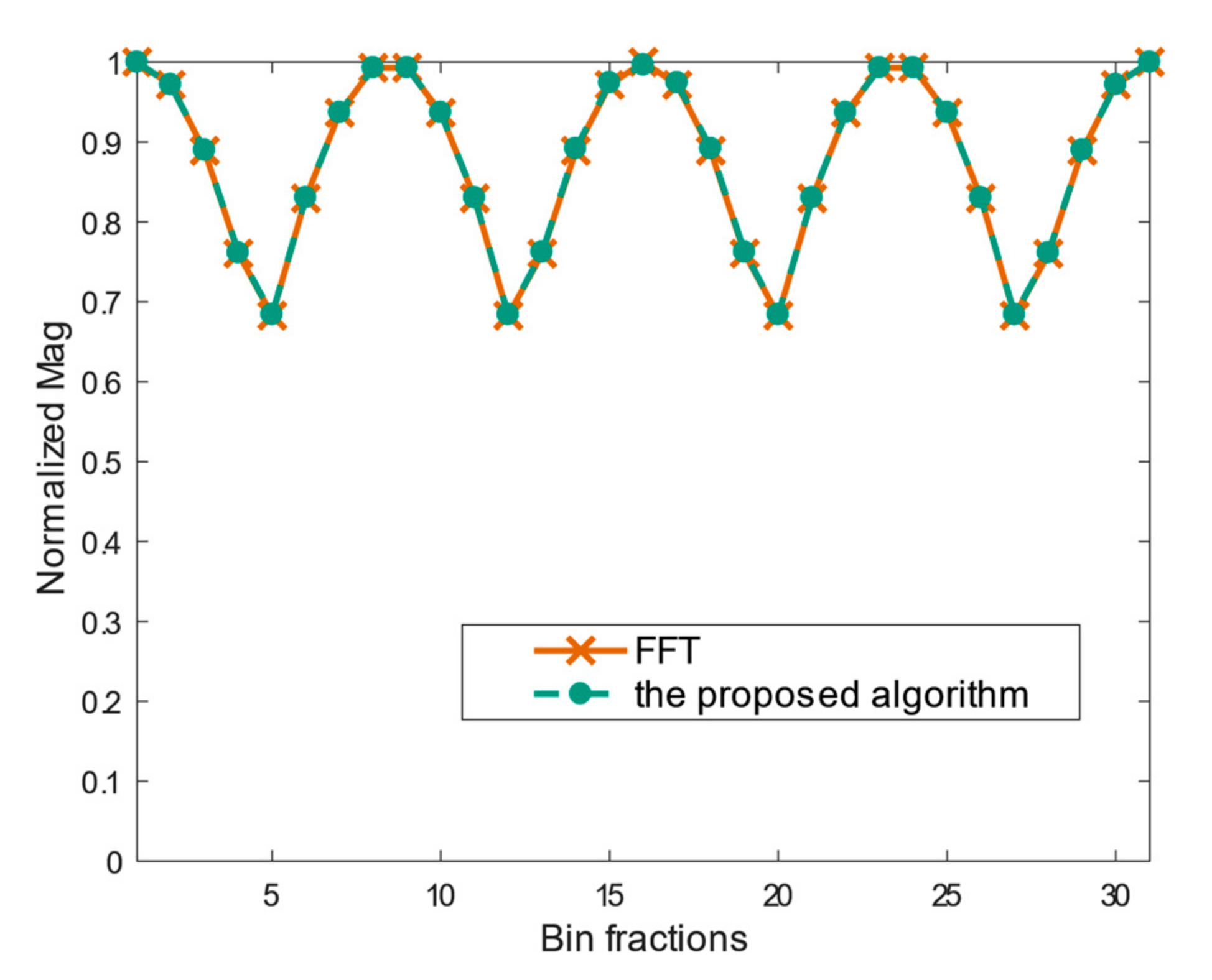
As can be observed from Figure 3, for the channelisation characteristics of the IWOLA filter bank, there was a gain depression near the border between the two adjacent channels due to the channelisation process. Therefore, it had an adverse influence on the characteristics of the proposed algorithm. We obtained the channelised gain flatness characteristics, as shown in Figure 9, by sweeping the frequency domain with 31 sinusoidal signals from the centre of one sub-channel to that of the neighbouring sub-channel and plotting the normalized magnitude. A lower amplitude gain was caused by the IWOLA filter bank near the border of the adjacent sub-channels. With the proposed algorithm, this problem was solved by changing the characteristics of the window function for the IWOLA filter bank, which did not influence the adjacent sub-bands due to the NMDFB. The characteristics of the window function can be improved by increasing its cut-off frequency by 1.4 times. We analysed the frequency channel gain flatness using a similar approach to Figure 9. We then plotted the normalized magnitude, as shown in Figure 10, which indicates that Gain depression near the border of the adjacent sub-channels was improved by changing the characteristics of the window function for the IWOLA filter bank. The improved frequency channel gain flatness characteristics were the same as those of the direct FFT. There was a gain fluctuation of approximately 0.32.
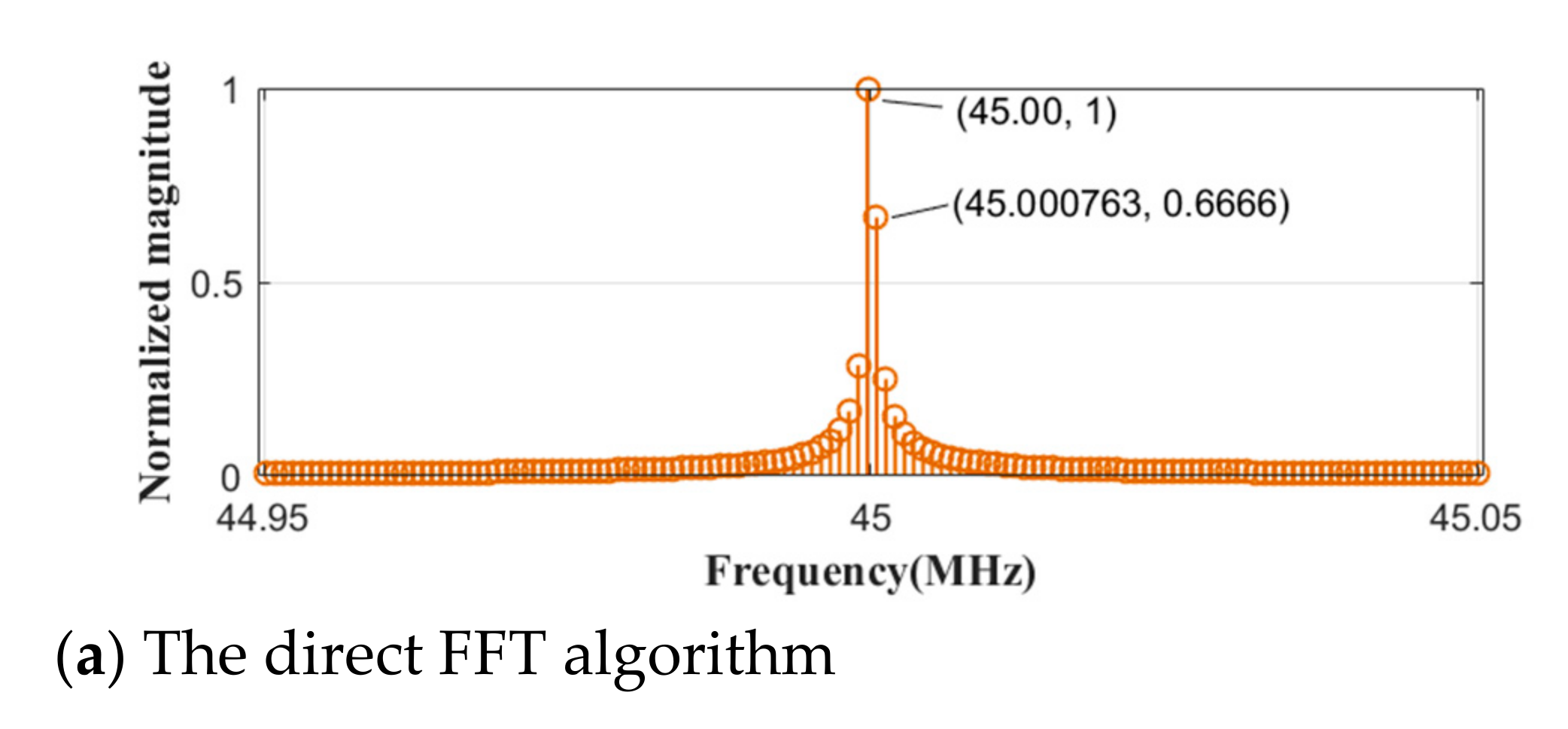
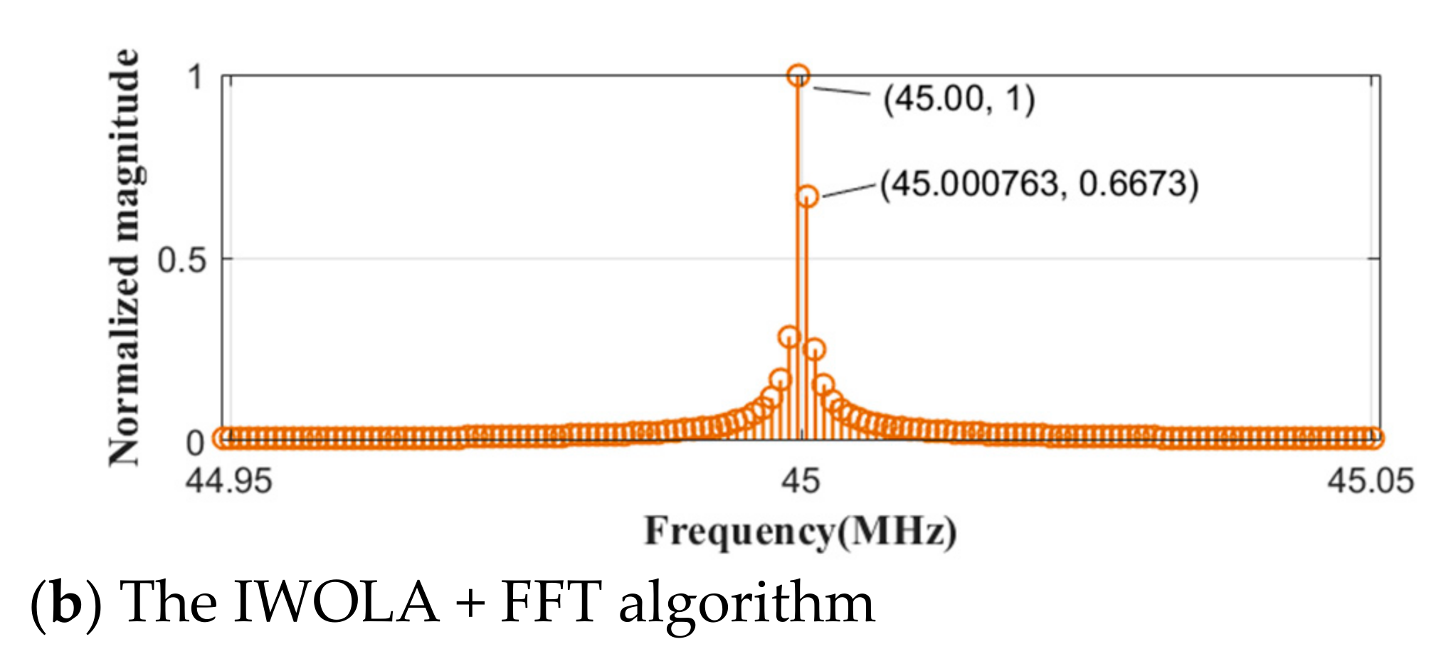
The flat channel characteristics of the IWOLA filter bank ensure that the IWOLA + FFT algorithm features the same spectral leakage as the direct FFT algorithm. A sinusoidal signal with a frequency of 45 MHz was inputted to the two algorithms, where K = 1024, N1 = 2048, fs = 800 MHz, D = 8, and the frequency resolution was approximately 763 Hz. We then plotted the spectral leakage characteristics, as shown in Figure 11.
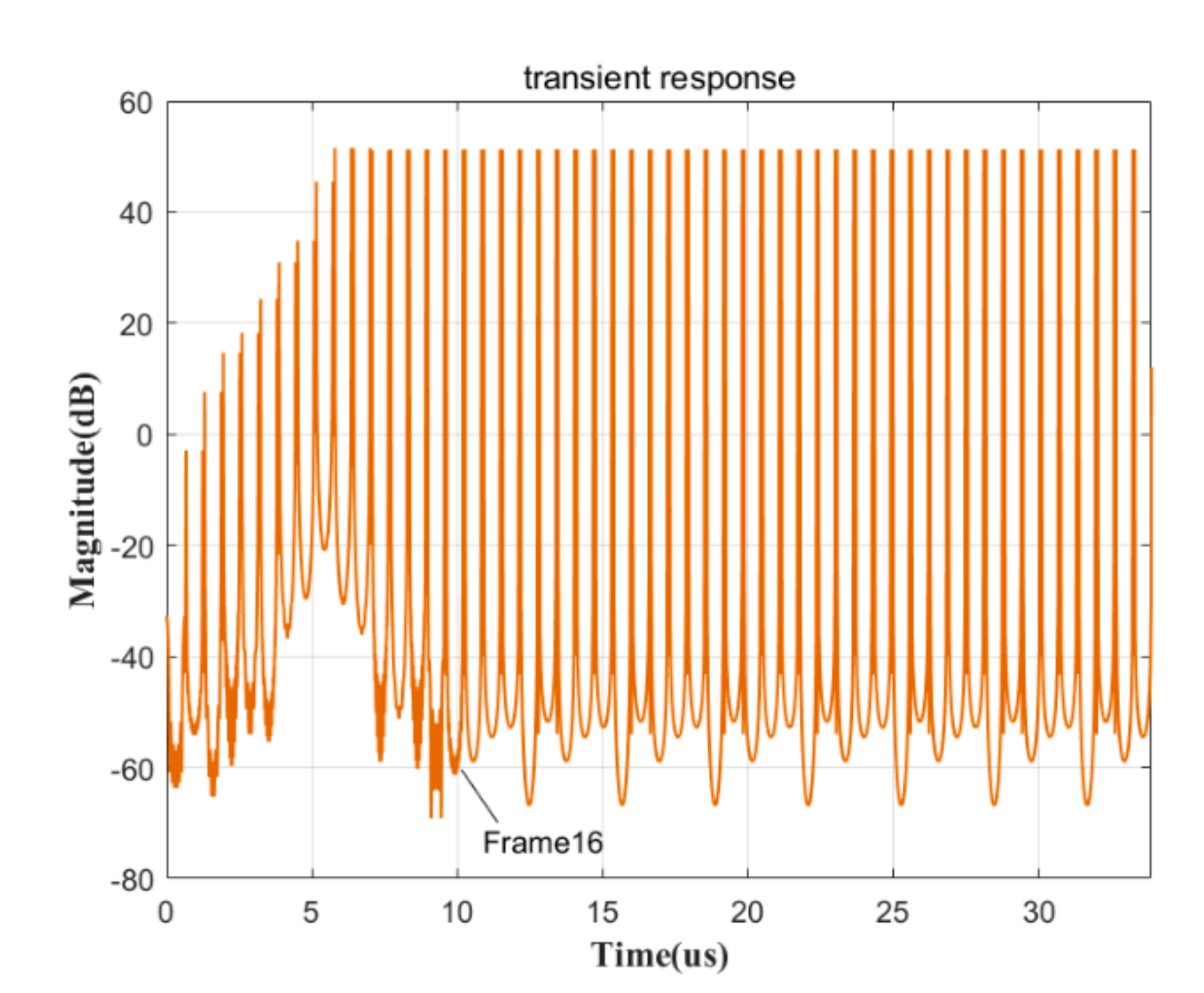
Under the assumption of streaming FFT processing, it is common knowledge that direct FFT demonstrates an excellent transient response. However, the IWOLA filter bank features a poor transient response, given that a long time period is required for the window function module to fill up data. The transient response of the IWOLA filter bank based on the input of a sinusoidal signal is plotted in Figure 12. As can be observed from the figure, the IWOLA filter bank output reached stability after the sixteenth frame (approximately greater than the decimation factor by a factor of two). This resulted in a decrease in resolution in the time-domain. However, the transient response time is not an issue for many radio astronomy applications, since a general accumulation process can be applied in radio astronomy to increase the signal-to-noise ratio (SNR) at the expense of a decrease in the time resolution.
The proposed algorithm uses the small-scale IWOLA filter bank and FFT instead of the ultra-large FFT calculation to perform spectral analysis on the broadband signals with an ultra-high-frequency resolution. As observed from the analysis results presented in the previous sections, the designed IWOLA filter bank in the IWOLA + FFT algorithm demonstrates flat channel characteristics. In addition, the proposed algorithm enhances the gain near the border of the two neighbouring sub-bands, with a channel characteristic that is identical to that of the second-stage direct FFT. To improve the channel characteristics, the second-stage FFT can be substituted with a WOLA filter bank, which is readily implementable.

4. Optimization of the IWOLA + FFT Algorithm

4.1. Architecture of the IWOLA + WOLA Algorithm

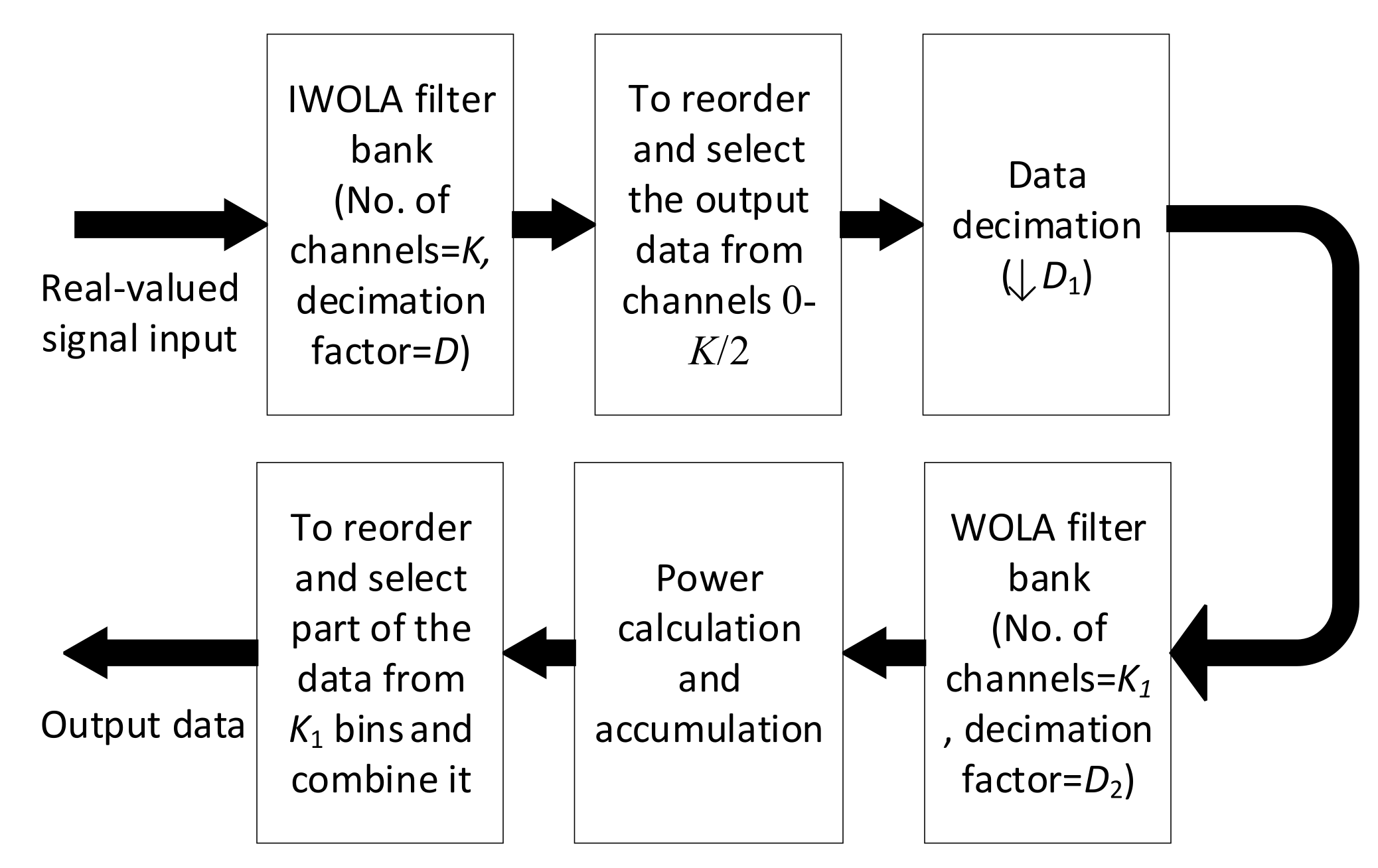
Based on the analysis results, the IWOLA + FFT algorithm can be used to perform ultra-large FFT calculations, with a nearly identical channel performance with respect to the ultra-large FFT, thus achieving spectral analysis with an ultra-fine frequency resolution. For improved channel characteristics, this paper proposes an IWOLA + WOLA algorithm by substituting the second-stage FFT with the WOLA filter bank to optimize the IWOLA + FFT algorithm. The overall framework of the IWOLA + WOLA algorithm is shown in Figure 13.
The three upper modules of the IWOLA + WOLA algorithm in Figure 13 are the same as those of the IWOLA + FFT algorithm. The WOLA filter bank outputs are the time-frequency spectrum for each subchannel ranging from 0–K/2. Therefore, the output data of the WOLA filter bank should be accumulated for linear frequency modulation (LFM) signals if the LFM signal is modulated within a long time-period. Otherwise the bandwidth of the LFM signals may be reduced after processing by the IWOLA + WOLA algorithm. In addition, the data accumulation for each sub-channel can improve the SNR. Before the output, the data of each sub-channel from the module of the power calculation and accumulation should then be re-ordered, given that the input data into the succeeding WOLA filter bank are complex. The re-ordering method is presented in Table 2. Furthermore, the re-ordered data should be partially selected to represent the entire sub-channel due to the NMDFB, as shown in Table 3. The number of selected data is K1/2. The selected data can then be combined into one group according to the order of the channel numbering.

4.2. Performance Comparison between the IWOLA + WOLA and IWOLA + FFT Algorithms

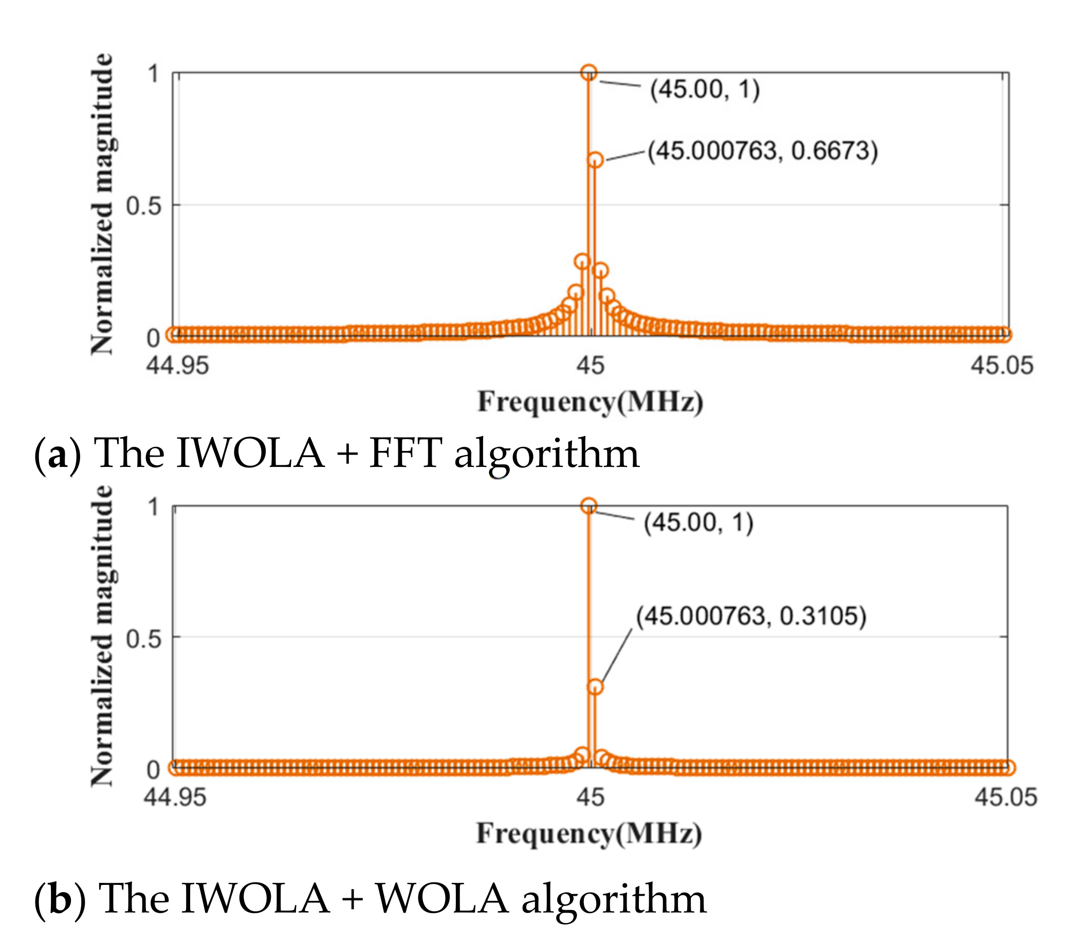
To demonstrate the advantages of the IWOLA+WOLA algorithm, a signal with a frequency of 45 MHz was inputted into the IWOLA + WOLA structure, IWOLA + FFT structure, where K = 1024, K1 = 2048, fs = 800 MHz, D = 8, and the frequency resolution was approximately 763 Hz. The spectral leakage characteristics were then plotted, as shown in Figure 14. As can be observed from the figure, the IWOLA + WOLA algorithm featured a spectral leakage less than that of the IWOLA + FFT algorithm by a factor of approximately 2.1.
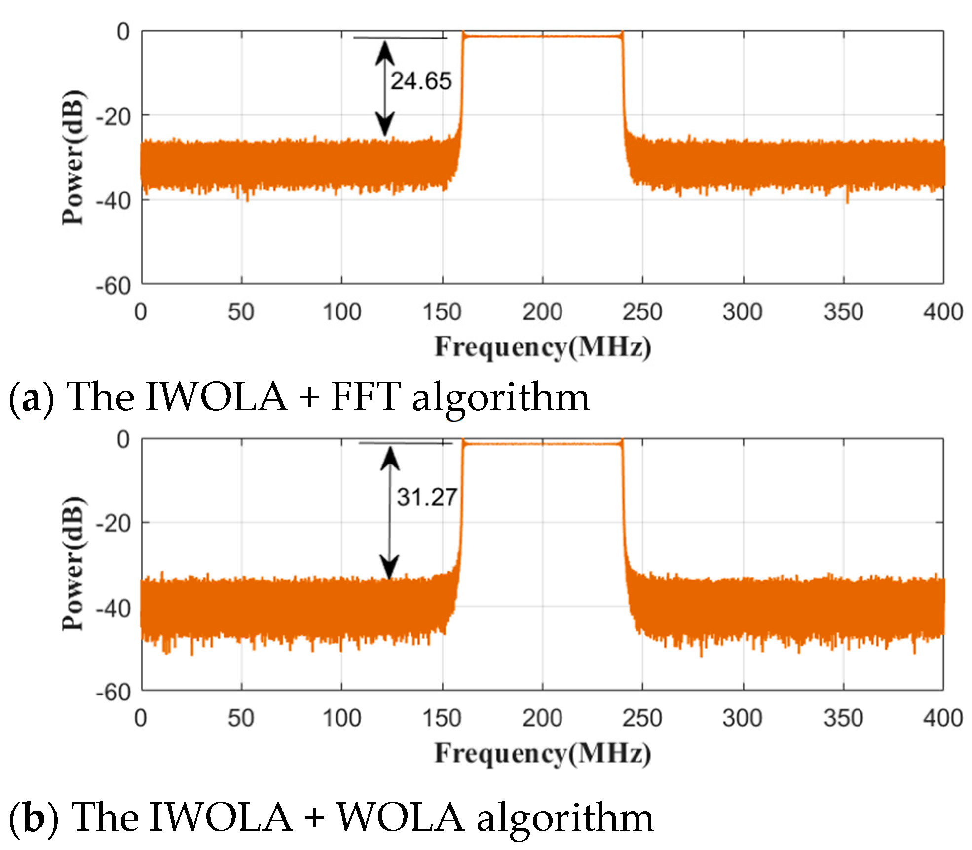
To analyse the SNRs of the IWOLA + WOLA and IWOLA + FFT algorithms, an input LFM signal with a frequency of 160 MHz, bandwidth of 80 MHz, and SNR of 30 dB was inputted to both algorithms, where K = 1024, K1 = 2048, fs = 800 MHz, D = 8, and the frequency resolution was approximately 763 Hz. The SNR performance was plotted as shown in Figure 15. As can be observed from the figure, the IWOLA + WOLA structure demonstrated an SNR of 31.27 dB, which was superior to that of the IWOLA + FFT structure (24.65 dB).
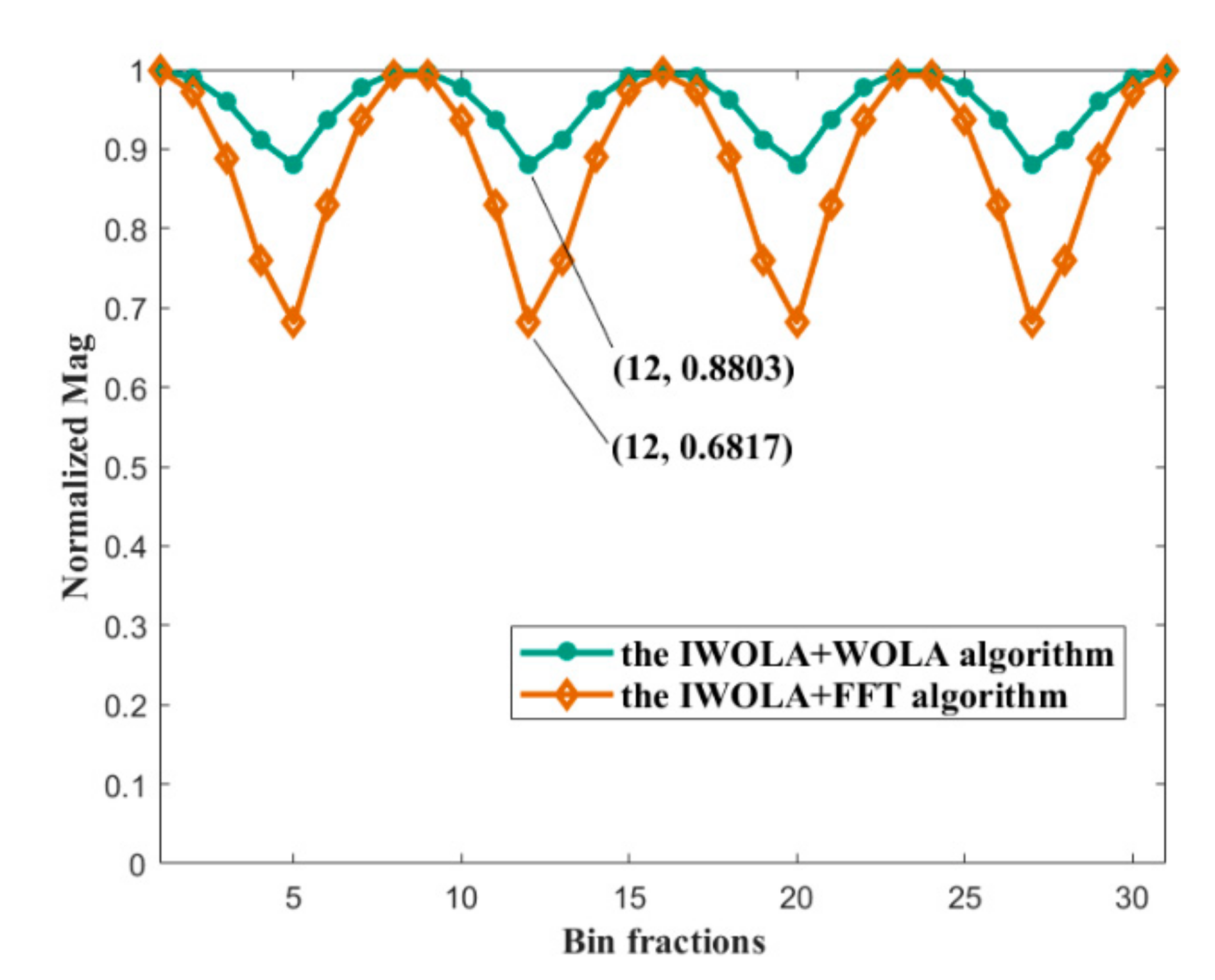
Furthermore, we analysed the channelised gain flatness characteristics of the IWOLA + WOLA and the IWOLA + FFT algorithms by scanning the spectrum from one sub-channel centre to an adjacent sub-channel centre using 31 sinusoidal signals. The channelised gain flatness characteristics are shown in Figure 16. The IWOLA + WOLA algorithm demonstrated a fluctuation range of approximately 0.12, whereas the IWOLA + FFT algorithm demonstrated a fluctuation range of approximately 0.32. Thus, the IWOLA + WOLA algorithm featured a fluctuation range that was smaller than that of the IWOLA + FFT algorithm.
Based on the analysis results above, although the IWOLA + WOLA algorithm uses a smaller two-stage FFT with high computation efficiency instead of an ultra-large FFT, which is similar to the IWOLA + FFT algorithm; the IWOLA + WOLA demonstrated a superior performance to the IWOLA + FFT algorithm and direct FFT algorithm.

5. Algorithm Simulation Analysis

To verify the accuracy and performance of the proposed broadband spectral analysis algorithms with a high-frequency resolution, the following simulation analyses were carried out in MATLAB (the version: R2017a). The following parameters were set according to Equations (4)–(6): K = 1024, D = 8, N1 = 2048, K1 = 2048, D2 = 8; and the sampling frequency of the real-valued signal fs = 800 MHz, D1 = 64, df = 763 Hz, and N2 = 1024. To analyse the algorithm performances, three types of methods were used to calculate the spectrum for the simulated signals. The first involved the direct performance of an ultra-large FFT (direct FFT) to obtain a spectral resolution of 763 Hz. The remaining two methods involved the use of the IWOLA + FFT and IWOLA + WOLA algorithms to achieve the same spectral resolution.
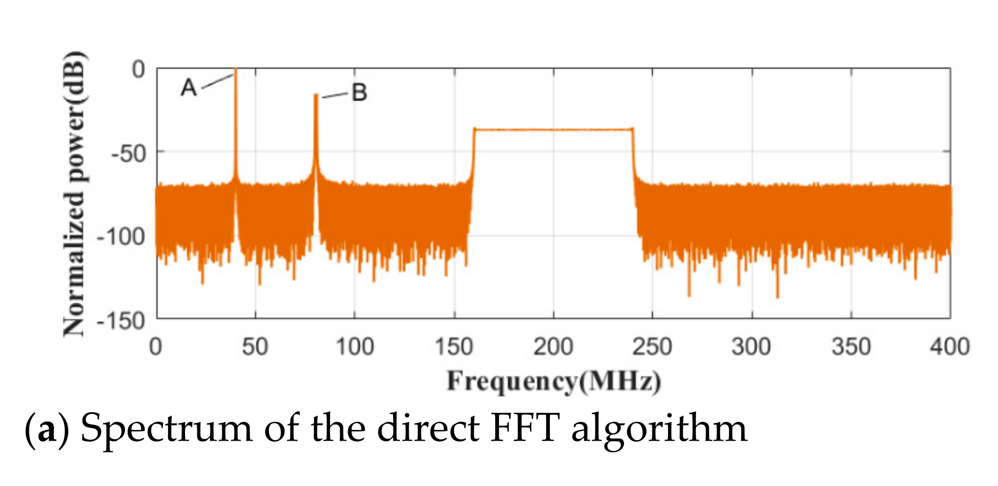
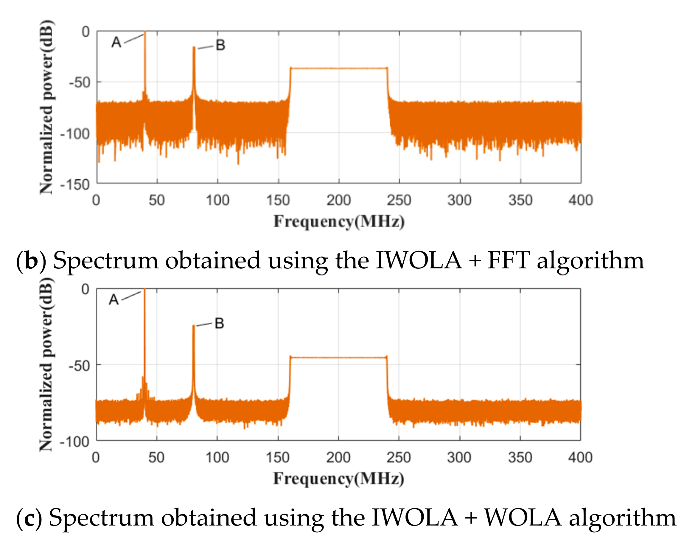
First, a real sinusoidal signal with a frequency of 40.00 MHz was inputted to the three algorithms, to evaluate their gains and SNRs, as shown in Figure 17. As can be observed from the figure, the IWOLA + FFT structure exhibited a gain increase of approximately 3 dB when compared with the direct FFT, and a nearly identical SNR. The IWOLA + WOLA structure exhibited a gain decrease of approximately 5 dB when compared with the IWOLA + FFT structure. However, this may not be significant, given that the SNR of the IWOLA + WOLA structure was 6 dB higher than that of the IWOLA + FFT structure. Thus, the gain of the IWOLA + WOLA can be any value, which can then be multiplied by a constant to meet the design requirements only if its SNR is equal or superior to that of the IWOLA + FFT algorithm. Furthermore, to further verify the accuracy of the proposed algorithms, we simultaneously inputted four signals into the three algorithms. The input signal consisted of two real sinusoidal signals with frequencies of 40.00 MHz and 40.000763 MHz, respectively, and two chirp signals, in addition to Gaussian white noise. The starting frequencies of the two chirp signals were 80 MHz and 160 MHz, respectively. Moreover, their bandwidths were 0.78125 MHz, which is equivalent to the subchannel bandwidth of the IWOLA filter bank, and 80 MHz, respectively. The spectral data obtained by the three methods are shown in Figure 18, where (a) presents a spectrum obtained by the direct FFT algorithm, (b) presents a spectrum obtained by the IWOLA + FFT algorithm, and (c) presents a spectrum obtained by the IWOLA + WOLA algorithm. There were two real sinusoidal signals at A, and one chirp signal at B, which are detailed further in this manuscript. As can be observed from the figure, the proposed algorithms demonstrated flat gain characteristics. The bandwidth of the second chirp signal occupies multiple sub-bands, but its gain between sub-bands are flat and identical.
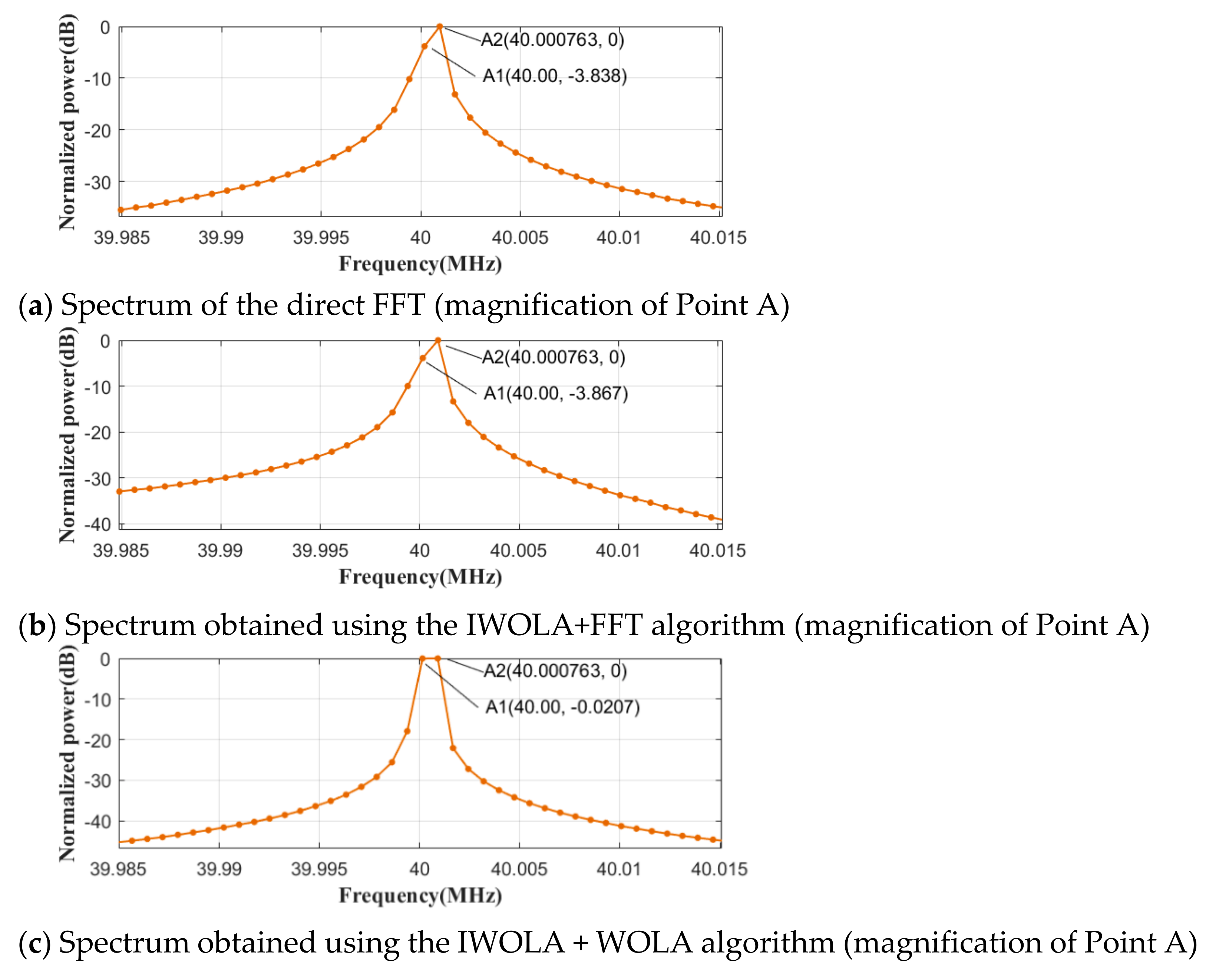
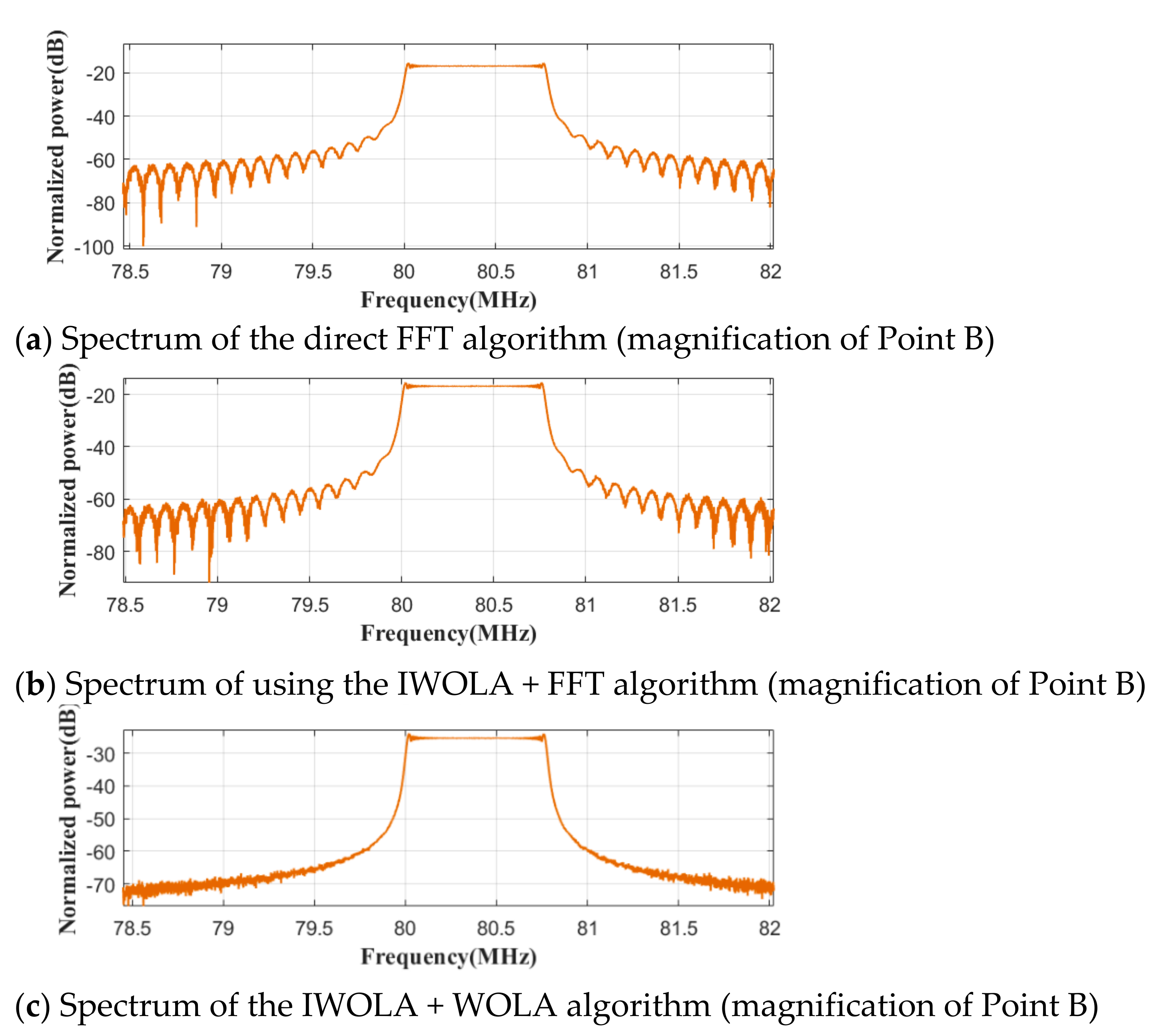
There were two real sinusoidal signals at A, with frequencies of 40 MHz and 40.000763 MHz. The magnified views for Point A in Figure 18 are shown in Figure 19. When comparing Figure 19a–c, the resultant spectra obtained by the direct FFT and IWOLA + FFT algorithms for the signal at Point A were the same, whereas the IWOLA + WOLA algorithm demonstrated a superior spectrum. The two proposed algorithms demonstrated the same frequency resolution as the direct FFT algorithm, namely, 763 Hz. The magnified views for Point B in Figure 18 are shown in Figure 20. The chirp signal frequency started at 80 MHz with a bandwidth of 0.78125 MHz, which was equal to each sub-band width of the IWOLA filter bank.
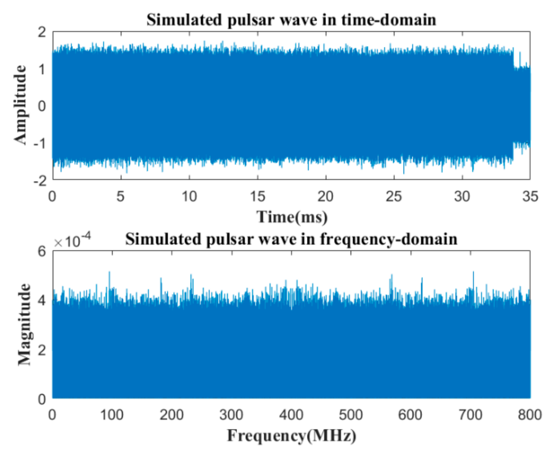
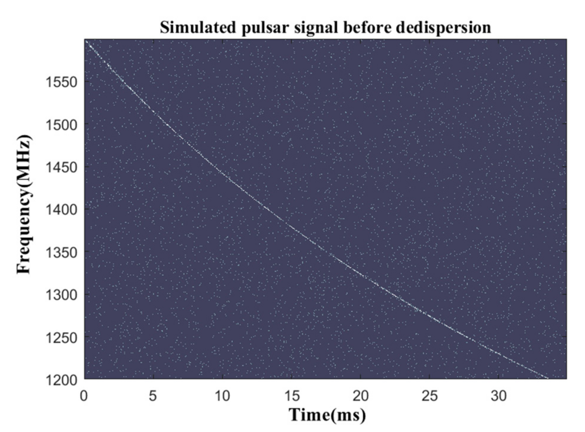
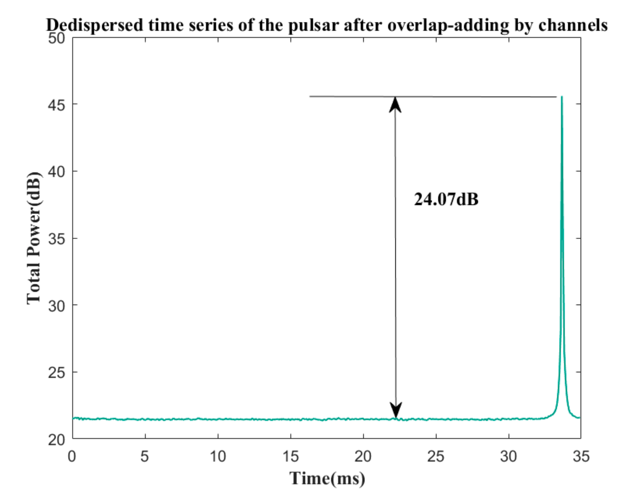
In addition, a coherent dispersed pulse was generated in MATLAB as a simulated pulsar signal, with a dispersion measure (DM) of 26.776 pc cm−3. The frequency ranged from 1200–1600 MHz, and its sampling frequency and observation time were 800 MHz and 35 ms, respectively. The simulated pulsar signal with a white Gaussian noise (SNR = 0 dB) is shown in Figure 21. By setting the decimation factor D = 8, the number of channels was set as K = 32, and the bin number K1 and the decimation factor D2 of the second-stage WOLA filter bank were 2048 and 8, respectively. The simulated pulsar signal was inputted to the proposed IWOLA + WOLA algorithm. This yielded the spectrum shown in Figure 22 with a frequency resolution of approximately 24.4 kHz. As can be seen from the figure that Before dedispersion, there was dispersion smearing at the observed frequencies within an observation duration of 35 ms. The pulsar was dispersed within a range of 1200–1600 MHz. After a direct dedispersion algorithm, the dispersed signal was aligned to the arrival time, which corresponded to 1200 MHz. The dedispersed signal is displayed in Figure 23. It was subjected to a succeeding overlap-adding processing, which yielded the dedispersed time series of the simulated pulsar, as shown in Figure 24. As can be observed from the figure, the SNR of the pulsar signal output from the IWOLA + WOLA algorithm was 24.07dB.
The simulation results revealed that the proposed IWOLA + WOLA algorithm demonstrated a superior accuracy and performance to the direct FFT and the IWOLA + FFT algorithms. The proposed IWOLA + FFT and IWOLA + WOLA algorithms solved the overlapping interference problem of the adjacent subchannels caused by the first-stage channelisation that is realised by an IWOLA filter bank. By selecting the appropriate K, D, D2, and K1 values, in addition to the operating frequency for hardware such as FPGAs, a broadband spectral analysis system can be designed with a satisfactory performance that consumes less resources.
6. Conclusions

Two broadband spectral analysis algorithms with an ultra-high-frequency resolution, namely, the IWOLA + FFT algorithm and the IWOLA + WOLA algorithm, are proposed in this paper. The IWOLA + FFT algorithm was constructed by combining an IWOLA filter bank with FFT, in addition to a specific decimation for the output data from the IWOLA filter bank and the data selection for the output data from the FFT. The algorithm disassembles an ultra-large-scale FFT process into two-stage processes. Hence, two small-scale FFTs are required, which can achieve flexibility for the system implementation. This implies that if the algorithm is implemented with hardware such as an FPGA, it is not necessary to design an ultra-large point FFT. The algorithm reduces the subsequent processing units by one set for real-valued signals by shifting the centre frequency of every sub-band of the WOLA filter bank by half of the frequency bin, conserves hardware resources, and decreases the implementation complexity according to the identity of each sub-band of the IWOLA filter bank. The IWOLA + FFT algorithm demonstrates a comparable spectral analysis performance to that of the direct FFT algorithm and eliminates the overlap interference between the adjacent channels within the entire Nyquist frequency bandwidth. To improve the channelised performance, the IWOLA + WOLA algorithm was further proposed and analysed, which includes the second-stage WOLA filter bank and accumulation module instead of the second-stage FFT. The IWOLA + WOLA algorithm demonstrates the same function as the IWOLA + FFT algorithm, with a superior spectral analysis performance. By changing the algorithm parameters K, D, D2, and K1, the spectral analysis can be readily performed with an ultra-high-frequency resolution and satisfactory performance. Future research will be focused on design implementation and optimization in a FPGA, and the deployment of the proposed schemes at an observatory.

Author Contributions

Funding acquisition, C.Y. and Q.M.; Methodology, X.W., J.H. and C.W.; Project administration, Q.M.; Writing—original draft, X.W. and T.W. All authors have read and agreed to the published version of the manuscript.

Funding

This research was funded by the National Natural Science Foundation of China, grant number U1731120, 61801153), the Natural Science Foundation of the Jiangsu Higher Education Institutions of China, grant number 17KJB160001, the CCIT Key Laboratory of Industrial IoT, grant number KYPT201803Z, the Changzhou Key Laboratory of High Technology, grant number CM20183004, the State Key Laboratory of Millimetre Waves, grant number K202012, the high-end research and study funding project for professional leaders of Jiangsu higher vocational colleges, grant number 2018GRGDYX011, and the Natural Science Foundation of Zhejiang province, grant number LQY20F010001.

Institutional Review Board Statement

Not applicable.

Informed Consent Statement

Not applicable.

Data Availability Statement

Not applicable.

Conflicts of Interest

The authors declare no conflict of interest.

References

  1. Nishimura, Y.; Shimonishi, T.; Watanabe, Y.; Sakai, N.; Aikawa, Y. Spectral Line Survey Toward a Molecular Cloud in Ic10. Astrophys. J. 2016, 829, 94. [Google Scholar] [CrossRef] [Green Version]
  2. Nishimura, Y.; Shimonishi, T.; Watanabe, Y.; Sakai, N.; Aikawa, Y.; Kawamura, A.; Yamamoto, S. Spectral Line Survey toward Molecular Clouds in the Large Magellanic Cloud. Astrophys. J. 2016, 818, 161. [Google Scholar] [CrossRef]
  3. Chin, Y.N.; Henkel, C.; Whiteoak, J.B.; Millar, T.J.; Lemme, C. Molecular abundances in the Magellanic Clouds I. A multiline study of five cloud cores. Astron. Astrophys. 1996, 317, 1–15. [Google Scholar]
  4. Brunt, C.M.; Heyer, M.H.; Mac Low, M.M. Turbulent driving scales in molecular clouds. Astron. Astrophys. 2009, 504, 883–890. [Google Scholar] [CrossRef]
  5. Benz, A.O.; Grigis, P.C.; Hungerbuhler, V.; Meyer, H.; Zardet, D. A broadband FFT spectrometer for radio and millimeter astronomy. Astron. Astrophys. 2005, 442, 767–773. [Google Scholar] [CrossRef] [Green Version]
  6. Hulse, R.A. The discovery of the binary pulsar. Rev. Mod. Phys. 1994, 66, 699. [Google Scholar] [CrossRef]
  7. Chennamangalam, J.; MacMahon, D.; Cobb, J.; Karastergiou, A.; Siemion, A.P.; Rajwade, K.; Armour, W.; Gajjar, V.; Lorimer, D.R.; McLaughlin, M.A.; et al. SETIBURST: A Robotic, Commensal, Realtime Multi-science Backend for the Arecibo Telescope. Astrophys. J. Suppl. Ser. 2017, 228, 21. [Google Scholar] [CrossRef] [Green Version]
  8. Dewey, R.J.; Taylor, J.H.; Weisberg, J.M.; Stokes, G.H. A search for low-luminosity pulsars. Astrophys. J. 1985, 294, L25–L29. [Google Scholar] [CrossRef]
  9. Gupta, Y.; Ajithkumar, B.; Kale, H.S.; Nayak, S.; Sabhapathy, S.; Sureshkumar, S.; Swami, R.V.; Chengalur, J.N.; Ghosh, S.K.; Ishwara-Chandra, C.H.; et al. The upgraded GMRT: Opening new windows on the radio Universe. Curr. Sci. 2017, 2017, 707–714. [Google Scholar] [CrossRef]
  10. Yin, Q.J.; Zhu, L.; He, L.S.; Dong, L.; Liu, J.Q. A new method to observe radio astronomy signal: Centimeter-decimeter spectral line—Based on high performance integrated circuit. Astron. Res. Technol. 2017, 14, 103–109. [Google Scholar] [CrossRef]
  11. Klein, B.; Hochgürtel, S.; Krämer, I.; Bell, A.; Meyer, K.; Güsten, R. High-resolution wide-band fast Fourier transform spectrometers. Astron. Astrophys. 2012, 542, L3. [Google Scholar] [CrossRef] [Green Version]
  12. Price, D.C.; Macmahon, D.H.E.; Lebofsky, M.; Croft, S.; Deboer, D.; Enriquez, J.E.; Foster, G.S.; Gajjar, V.; Gizani, N.; Hellbourg, G.; et al. The breakthrough listen search for intelligent life: Wide-bandwidth digital instrumentation for the csiro parkes 64-m telescope. Publ. Astron. Soc. Aust. 2018, 35, e041. [Google Scholar] [CrossRef] [Green Version]
  13. Reddy, S.H.; Kudale, S.; Gokhale, U.; Halagalli, I.; Raskar, N.; De, K.; Gnanaraj, S.; Ajith Kumar, B.; Gupta, Y. A Wideband Digital Back-End for the Upgraded GMRT. J. Astron. Instrum. 2017, 1, 1641011. [Google Scholar] [CrossRef]
  14. Zhang, X.; Yu, X.X.Y.; Duan, R.; Li, D.; Hao, J.; Jin, C.J. FAST digital backend and algorithm simulation for broadband million channel spectrometer. Prog. Astron. 2016, 34, 249–257. [Google Scholar] [CrossRef]
  15. Bunton, J. CSIRO Telecommunications and Industrial Physics. Alma Memo 2003, 447, 1–10. [Google Scholar]
  16. Harris, C.; Haines, K. A mathematical review of polyphase filterbank implementations for radio astronomy. Publ. Astron. Soc. Aust. 2011, 28, 317–322. [Google Scholar] [CrossRef] [Green Version]
  17. Tuthill, J.; Hampson, G.; Bunton, J.; Brown, A. Development of multi-stage filter banks for ASKAP. In Proceedings of the 2012 International Conference on Electromagnetics in Advanced Applications, ICEAA’12, Cape Town, South Africa, 2–7 September 2012; pp. 1067–1070. [Google Scholar] [CrossRef]
  18. Price, D.C. Spectrometers and Polyphase Filterbanks in Radio Astronomy. arXiv 2016, arXiv:1607.03579. [Google Scholar]
  19. Naldi, G.; Bartolini, M.; Mattana, A.; Pupillo, G.; Hickish, J.; Foster, G. Developments of FPGA-based digital back-ends for low frequency antenna arrays at Medicina radio telescopes. Mem. Della Soc. Astron. Ital. 2017, 88, 206–217. [Google Scholar]
  20. McSweeney, S.J.; Ord, S.M.; Kaur, D.; Bhat, N.D.R.; Meyers, B.W.; Tremblay, S.E.; Jones, J.; Crosse, B.; Smith, K.R. MWA tied-array processing III: Microsecond time resolution via a polyphase synthesis filter. Publ. Astron. Soc. Aust. 2020, 37, e034. [Google Scholar] [CrossRef]
  21. Melis, A.; Concu, R.; Trois, A.; Possenti, A.; Bocchinu, A.; Bolli, P. SArdinia Roach2-based Digital Architecture for Radio Astronomy. J. Astron. Instrum. 2018, 7, 1850004. [Google Scholar] [CrossRef] [Green Version]
  22. Wang, X.H.; Meng, Q.; Han, J.L.; Liu, W.; Zhang, J.W. Flexible Filter Bank Based on an Improved Weighted Overlap-Add Algorithm for Processing Wide Bandwidth Radio Astronomy Signals. Publ. Astron. Soc. Pac. 2015, 127, 1263–1268. [Google Scholar] [CrossRef]
  23. Yang, L.X. Modern Digital Signal Processing; Science Press: Beijing, China, 2007. [Google Scholar]
  24. Crochiere, R.E.; Rabiner, L.R. Multirate Digital Signal Processing, 1st ed.; Prentice Hall: Englewood Cliffs, NJ, USA, 1983. [Google Scholar]
  25. Heller, P.N.; Karp, T.; Nguyen, T.Q.; Heller, P.N.; Karp, T.; Nguyen, T.Q. A general formulation of modulated filter banks. IEEE Trans. Signal Process. 1999, 47, 986–1002. [Google Scholar] [CrossRef]
  26. Klein, B.; Philipp, S.D.; Güsten, R.; Krämer, I.; Samtleben, D. A new generation of spectrometers for radio astronomy: Fast Fourier transform spectrometer. Millim. Submillim. Detect. Instrum. Astron. 2006, 6275, 627511. [Google Scholar] [CrossRef]
  27. Ravinder, K.; Khader, M.A.; Rao, H.N.; Tech, M. Implementation of Scaled Down Model of Heterogeneous Spectrometers for Radio Astronomy Applications Using Xilinx Fpgas. J. Eng. Res. Appl. 2013, 3, 1596–1599. [Google Scholar]
  28. Sudharman, S.; Bindiya, T.S. Reconfigurable Non-Maximally Decimated Filter Bank based wideband channelizer for VLBI 2017. In Proceedings of the IEEE 30th Canadian Conference on Electrical and Computer Engineering (CCECE), Windsor, ON, Canada, 30 April–3 May 2017; pp. 1–4. [Google Scholar]
Figure 1. IWOLA + FFT algorithm framework.
Applsci 11 10262 g001
Figure 2. Aliasing effect in MDFB and NMDFB (fs represents the sampling frequency and D represents a decimating factor. The aliasing effect is avoided in the NMDFB).
Applsci 11 10262 g002
Figure 3. Frequency response of the channels in the IWOLA filter bank (where D denotes a decimating factor for the IWOLA filter bank).
Applsci 11 10262 g003
Figure 4. Frequency response of the channels in the WOLA filter bank (where D denotes a decimating factor for the WOLA filter bank).
Applsci 11 10262 g004
Figure 5. Diagram of the actual bandwidth and sampling rate for each subchannel of a N1-point FFT.
Applsci 11 10262 g005
Figure 6. Gain flatness feature between two adjacent sub-channels of the IWOLA filter bank and the direct FFT.
Applsci 11 10262 g006
Figure 7. Scalloping loss of the IWOLA filter bank and the direct FFT. The results revealed that the IWOLA filter bank exhibited a flatter gain feature than the FFT.
Applsci 11 10262 g007
Figure 8. Scalloping loss of the IWOLA + FFT algorithm and the direct FFT.
Applsci 11 10262 g008
Figure 9. Channelised gain flatness characteristics.
Applsci 11 10262 g009
Figure 10. Improved channelised gain flatness characteristics of the IWOLA + FFT algorithm.
Applsci 11 10262 g010
Figure 11. Comparison of the spectral leakage.
Applsci 11 10262 g011aApplsci 11 10262 g011b
Figure 12. Transient response of the IWOLA filter bank.
Applsci 11 10262 g012
Figure 13. The IWOLA + WOLA algorithm framework.
Applsci 11 10262 g013
Figure 14. Comparison of the spectral leakage.
Applsci 11 10262 g014
Figure 15. The SNR comparison. The SNR for the IWOLA + WOLA algorithm was 6.62 dB higher than that of the IWOLA + FFT algorithm.
Applsci 11 10262 g015
Figure 16. Comparison of channelised gain flatness characteristics.
Applsci 11 10262 g016
Figure 17. Spectrum gain and SNR for the three algorithms (for a sinusoidal signal with a frequency of 40 MHz).
Applsci 11 10262 g017
Figure 18. Comparison of the simulation analysis.
Applsci 11 10262 g018aApplsci 11 10262 g018b
Figure 19. Comparison between the simulation analysis results (magnification of Point A).
Applsci 11 10262 g019
Figure 20. Comparison of the simulation analysis results (magnification of Point B).
Applsci 11 10262 g020
Figure 21. Coherent dispersed pulses with noise.
Applsci 11 10262 g021
Figure 22. Spectrogram of the simulated pulsar obtained by the proposed algorithm (before dedispersion).
Applsci 11 10262 g022
Figure 23. Spectrogram of the simulated pulsar obtained by the proposed algorithm (after dedispersion).
Applsci 11 10262 g023
Figure 24. Dedispersed time series of the pulsar after overlap-adding by the channels (overlap-adding for all the 16,384 channels).
Applsci 11 10262 g024
Table 1. Bin selection and sorting diagram. It should be noted that fs is a sampling frequency. A signal within the bandwidth of fs/2 is first split into K sub-bands. Each of the first K/2 sub-bands are divided into N1 FFT bins. Sub-bands 0–K/2 represent complex signals. Consequently, the number of selected FFT bins for Sub-bands 0–K/2–1 are all N2. By selecting the appropriate bins from the N1 FFT bins for each sub-band, the frequency-domain data for the real-valued signals within fs/2 are obtained.
Bandwidth = fs/2
Sub-Bands 0–K/2–1 (Complex Signal)
01N2/2–1N1–1N1–2N1N2/2
Table 2. Bin reordering diagram for each sub-band (where K1 is the bin number of the second-stage WOLA filter bank, and all data feeding into the WOLA filter bank are complex).
Bandwidth = fs/(D * D1)
Each Sub-Band (Complex Signal)
Before re-order01K1/2 − 1K1/2K1/2 + 1K1 − 1
After re-order0K1 − 1K1/2 + 1K1/2K1/2 − 11
Table 3. Bin selection diagram for each sub-band (where K1 is the bin number of the second-stage WOLA filter bank, and all data feeding into the WOLA filter bank are complex. The number of selected data for each sub-channel is K1/2).
Bandwidth = fs/(D * D1)
Each Sub-Band (Complex Signal)
Before data selection01K1 − 1
After data selectionK1/2 − K1/4K1/2 − K1/4 + 1K1/2K1/2 + 1K1/2 + K1/4 − 1
Publisher’s Note: MDPI stays neutral with regard to jurisdictional claims in published maps and institutional affiliations.