Abstract
With the gradual increase of the cargo weight of heavy-haul trains, the traditional ballasted track with the accumulation of stone and ballast has been unable to meet its structural safety requirements. From the comparison of the three common ballastless tracks in China, it can be seen that the low-vibration track (LVT) has the advantages of reasonable structure, low cost, and easy maintenance. Therefore, the design and research of heavy-haul railways are focused on, and it is urgent to study the applicability of LVT in heavy-haul railways. Method: By improving the slope of the short side of the LVT support block, the support block has a better load bearing capacity, so as to achieve the purpose of bearing a larger axle load. Through 1:1 full-scale model test and finite element simulation, the static mechanical properties of Improved LVT (ILVT) and Traditional LVT (TLVT) are compared and analyzed. Result: Compared with TLVT, ILVT has smaller vertical displacement and track gauge changes when subjected to the same load. The proven and reliable finite element model also shows that ILVT’s load sharing is less affected. In the case of achieving the same deformation, ILVT can withstand greater vertical and lateral loads. Conclusions: Compared with the TLVT, the ILVT design can reduce the vertical displacement of the rail and the supporting block, better control the track subsidence, and improve the driving safety of the LVT. At the same time, ILVT improves the anti-overturning ability of the rail and support block under lateral load, reduces the expansion of the gauge and the lateral spacing of the support block, and improves the stability of the track structure. ILVT can also be considered for the weight of 40t and other large axle load, and has broad application prospects.
1. Introduction
1.1. Engineering Background
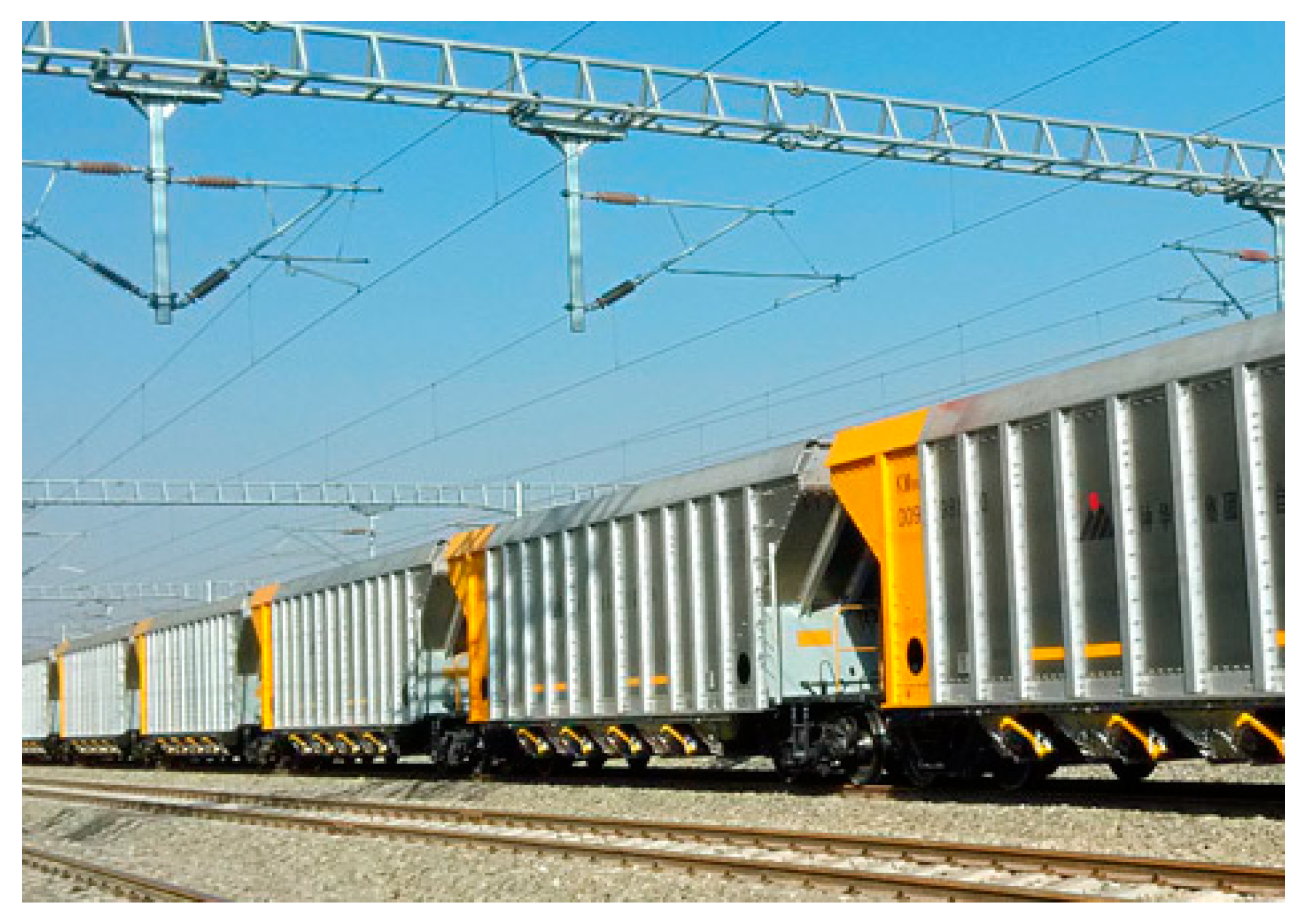
The axle load of heavy-haul railway trains is generally greater than 27t [1]. With the continuous development of social and economic needs, the axle load of heavy-haul trains has become larger and larger (Figure 1) [2], and the previous ballasted track structures built with stone ballast have gradually become difficult to meet their stress requirements. Ballasted tracks are often damaged during the operation of heavy-haul trains, leading to frequent repairs by workers, increasing maintenance costs, and affecting train operation [3,4,5]. Moreover, the length of newly-built heavy-haul railway tunnels is generally as long as 1~2 km, because the height of the carriages of heavy-haul trains has also increased a lot [6]. Therefore, if the heavy-haul railway continues to use the traditional ballasted track, it is necessary to build a tunnel with a larger space, which is not only difficult to construct, but also has a high safety risk [7].

Figure 1.
Heavy-haul train with increasing axle load.
At present, with the development of China’s high-speed railways and urban subways, ballastless tracks have been successfully applied to train lines with low axle loads such as high-speed railway EMUs and subway trains [7], especially the emergence of various types of ballastless tracks with superior performance and the maturity of related technologies [8]. Whether the ballastless track can be applied to heavy-haul railways, which have a relatively large train load, has also become the frontier of the railway engineering research field, and many scientific research institutions have also conducted extensive research on it [9].
However, there is no engineering practice of heavy-haul railway ballastless track in the world. The ballastless track structures used in China mainly include double-block track (DBT), long sleeper buried track (LSBT) and low-vibration track (LVT) [10].
- (1)
- DBT
DBT (Figure 2) is mainly composed of steel rails, elastic fasteners, double-piece sleepers, etc. [11]. The sleepers are prefabricated by the factory. The sleepers are assembled into rail rows during construction, and the sleepers are poured into the reinforced concrete track bed by pouring concrete on site. The main advantages of the DBT structure are the following: strong structural integrity, simple construction technology, easy-to-master production technology for prefabricated sleepers, complete domestic production equipment and convenient transportation and lifting, better economy. The main shortcomings are the following: cracks are likely to occur on the joint surface of the track bed slab and the old and new concrete of the sleeper, and crack control is difficult; the tool rail construction is used, and the construction quality is affected by the tool rail, fasteners, etc.; it is also difficult to repair during operation.
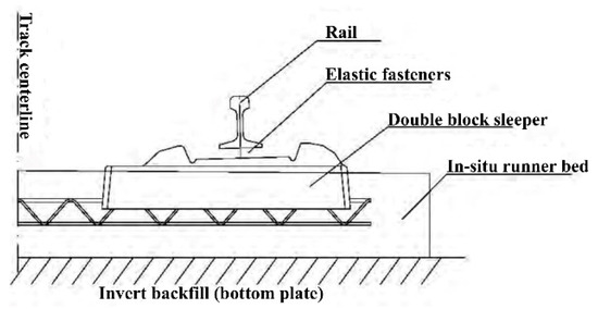
Figure 2.
DBT structure.
- (2)
- LSBT
The LSBT structure (Figure 3) mainly includes concrete track bed slabs, perforated sleepers and supporting fasteners [12,13,14]. LSBT uses pre-stressed long sleepers, poured into a reinforced concrete track bed. In order to ensure the connection between the sleepers and the track bed, 5 lateral reserved holes are set on the sleepers, and longitudinal steel bars are used to penetrate the track bed to enhance its integrity. The main advantages of the LSBT structure are the following: simple structure, good integrity, strong track gauge retention ability; good economy; concrete pouring and molding of the track bed are conventional construction techniques, easy to master; sleeper manufacturing, transportation and hoisting are convenient. The main shortcomings are the following: the new and old concrete junction area is larger, crack control is more difficult; the weight of prefabricated sleepers is larger, compared with DBT, it is more difficult to transport, assemble and lay.

Figure 3.
LSBT structure.
- (3)
- LVT
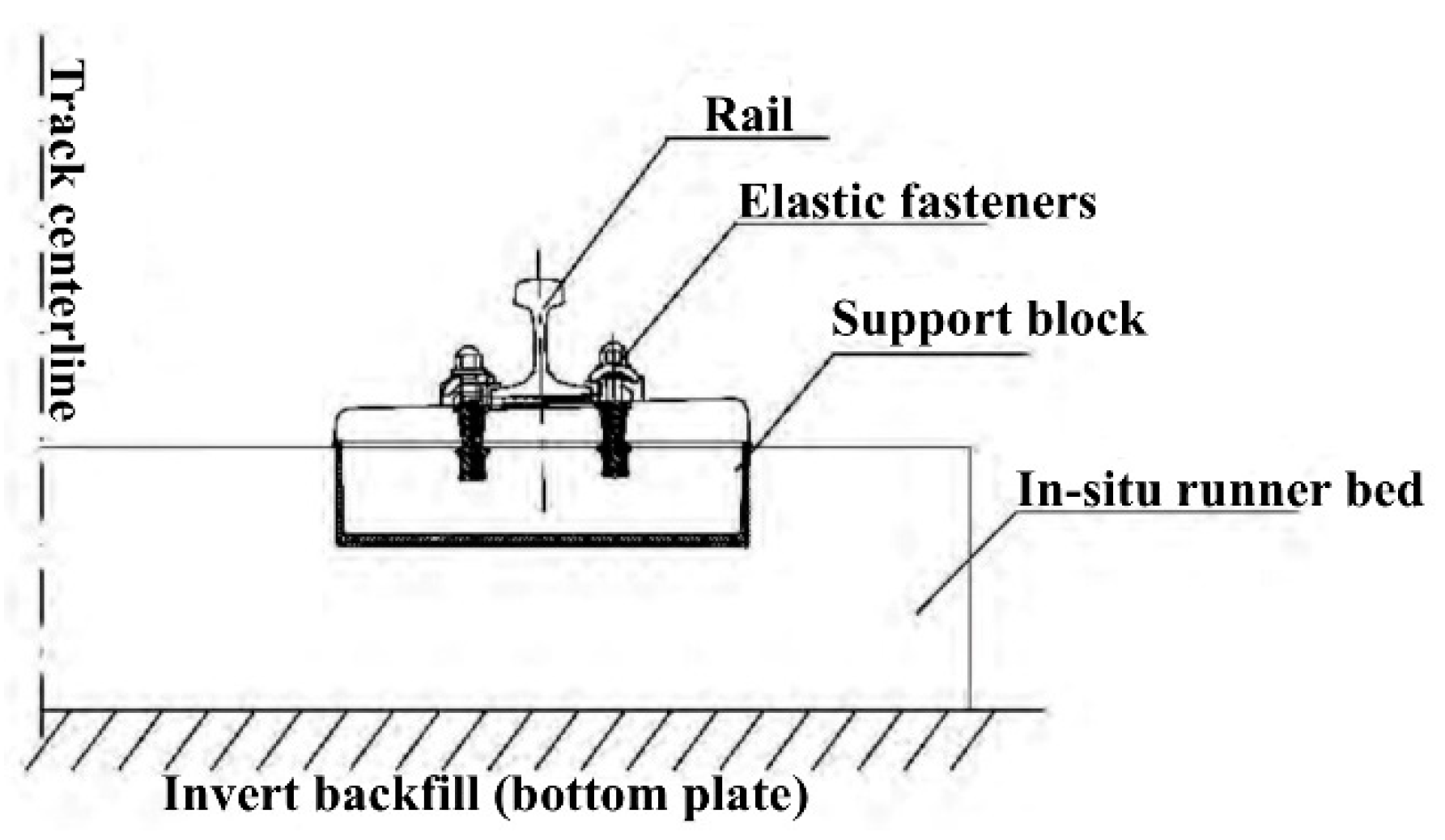
The LVT structure (Figure 4) mainly includes concrete track bed slab, elastic support block (concrete support block, rubber boot cover, rubber pad under the block) and supporting fasteners [15]. LVT is composed of rubber or other elastic composite boots at the lower part and around the double-piece sleeper (or two independent support blocks). There is a rubber elastic cushion between the bottom of the sleeper block and the boots, and concrete is poured around the boots. The main advantages of the structure are the following: the track structure has good elasticity; the construction process is simple; the structure can be repaired and the performance is better; the prefabricated parts are easy to hoist. The main disadvantages are the following: poor waterproof and dustproof performance of boots; durability of elastic elements in the structure; relatively weak retaining ability of track geometry.
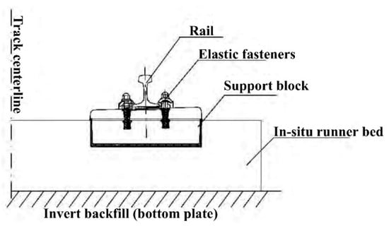
Figure 4.
LVT structure.
Since the three ballastless track structures all have good safety and reliability, they can be applied to heavy-haul railway operating conditions after the structural design is perfect. However, in view of the operational characteristics of heavy-haul railways, the selection analysis of the ballastless track structure is carried out from the aspects of low dynamic characteristics, repairability and good durability.
Both DBT and LSBT track structures are cast-in-place sleeper monolithic track bed structures, and the track elasticity is mainly provided by the fastener system. Under heavy-load transportation conditions, if the fastener structure is to maintain the gauge and the elastic cushion has good fatigue resistance, the stiffness of the elastic cushion of the fastener should not be too low. This makes the overall rigidity of the track larger, and the impact load of the train will be aggravated, which will adversely affect the integrity and durability of the track structure. In addition, the joint surface of the new and old concrete of the sleeper and the track bed slab is prone to cracks, and its mechanical characteristics still need further theoretical analysis and experimental comparative research.
At present, there is no experience in large-scale use of DBT and LSBT in China’s mixed passenger and freight lines, and the long-term suitability of the track structure is still lacking in operational practice. According to relevant data, DBT has been laid in several tunnels on the Sui-Yu line of China Railway. After a few years of passing trucks, loose sleepers and cracks in the track bed slab appeared to varying degrees; Several tunnels on the Yuhuai line have been paved with LSBT, and since the opening of operation, there have been diseases such as sinking of the overall track bed, loose sleepers, and serious slurry eruption, which caused large changes in the geometric dimensions of the line. In addition, these two ballastless track structures are difficult to repair after they are damaged.
The LVT is provided with elastic cushions under the concrete supporting blocks and under the rails, and the overall track flexibility is good, which is conducive to reducing the wheel-rail interaction force under heavy-load transportation conditions and improving the stress environment of the track structure. LVT has been successfully applied to the Qinling Tunnel on the Xikang Line in China and the Wushaoling Tunnel on the Lanwu Second Line and other passenger and freight mixed transport lines, and the cumulative laying of more than 300 km has been completed. The Qinling Tunnel and Wushaoling Tunnel have been in operation for nearly 10 years. The LVT structure is in good overall condition in the stable section of the tunnel base. In addition, compared with the double-block type, after the concrete supporting block is damaged and the tunnel base has local diseases, the LVT can be repaired better.
In summary, LVT has good overall performance and has a certain scale of engineering application in China. It has accumulated more experience in construction and maintenance and is a relatively mature structure. In addition, relative to the rigid track bed, there is a certain degree of repairability after the concrete supporting block is damaged and the tunnel is locally damaged. Therefore, the focus is on the selection of LVT structure for heavy-haul railways.
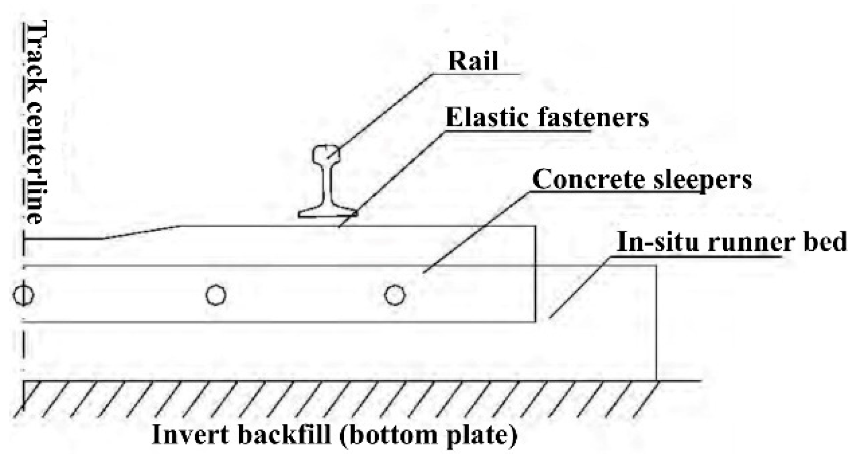
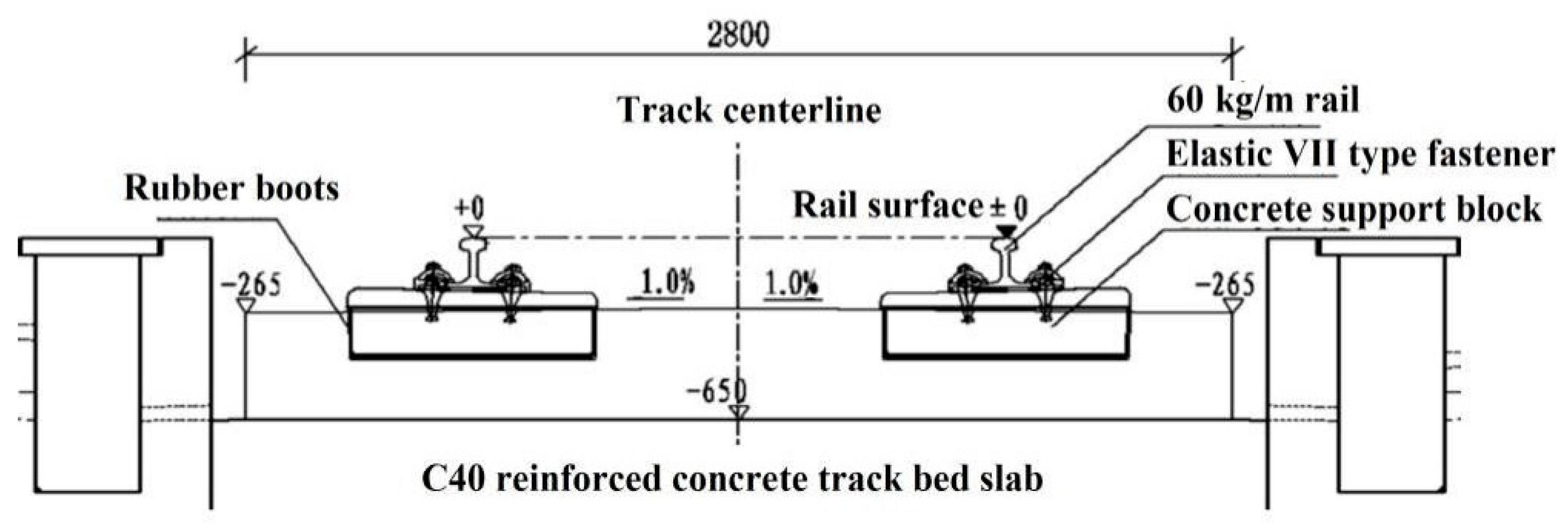
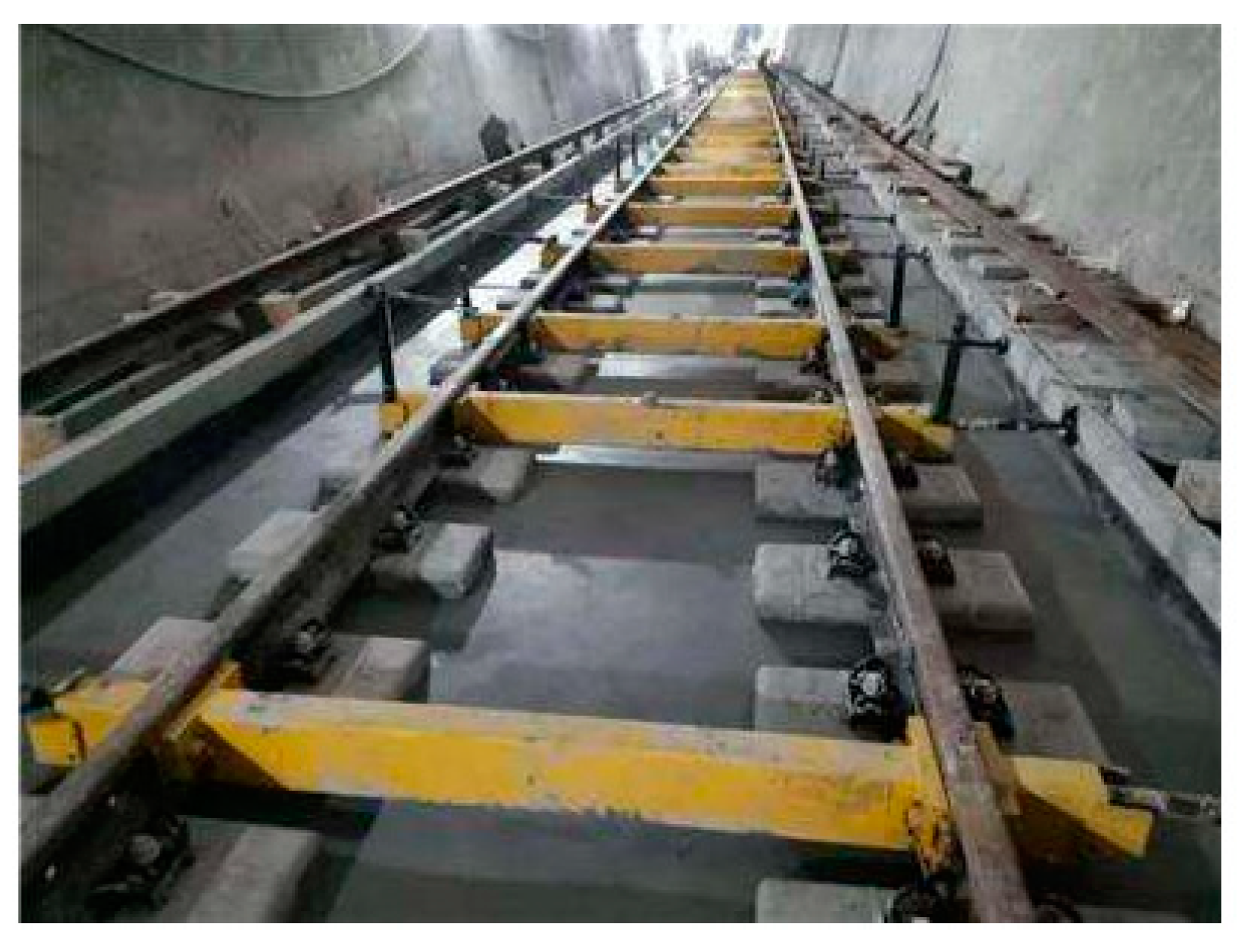
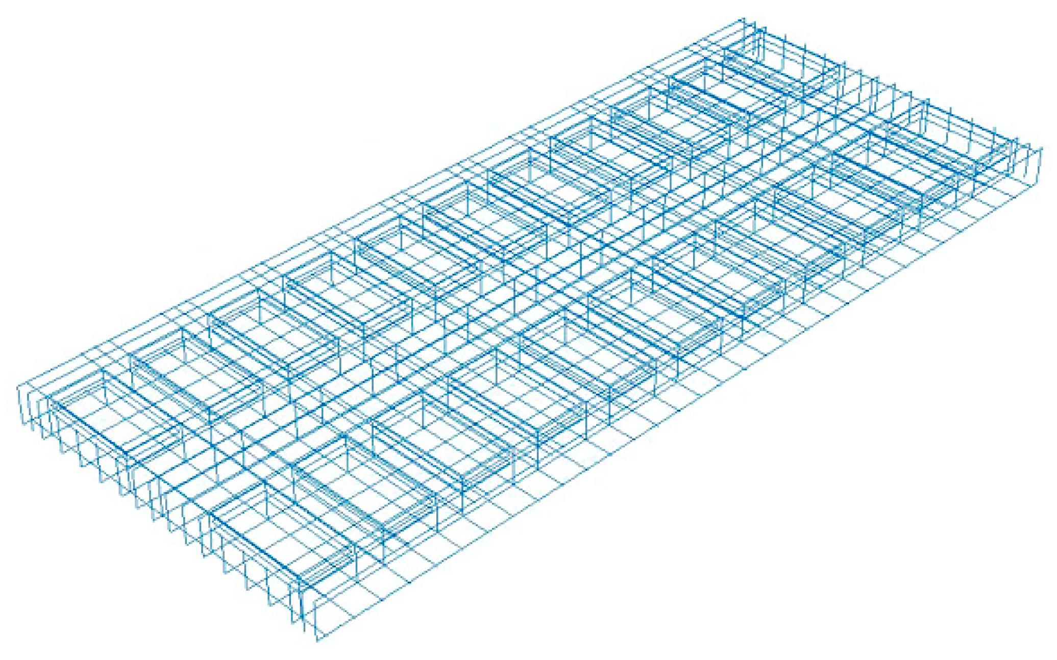
The LVT structure (Figure 5) is composed of rails, pre-embedded iron seat fasteners, supporting blocks, rubber boots, lower pads, and track bed slabs, etc. The elasticity of the track structure is provided by rubber boots, under-block rubber pads and fastener systems [9]. Compared with DBT and slab ballastless track, LVT has the advantages of low cost, good elasticity and vibration reduction performance, and convenient maintenance and repair. Compared with other types of ballastless track types, LVT has lower cost and better economy [15]. Therefore, the LVT system has been widely used in domestic and foreign railways and urban rail transit tunnels, such as the English Channel Tunnel, China Yiwan Line, Xiangyu Line, Qiangui Line, Xikang Line, Lanwu Second Line, Hong Kong Metro, Guangzhou Metro, and the United States Atlanta subway and so on. It is highly adaptable to the characteristics of heavy-haul railways, such as high traffic density, short skylight time, large area in the form of tunnels (Figure 6), and widespread distribution in sparsely populated areas. Comprehensive analysis shows that LVT has a good application prospect in the field of heavy-haul railways.
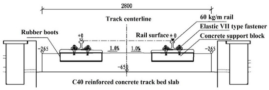
Figure 5.
Cross-sectional view of LVT in the tunnel.
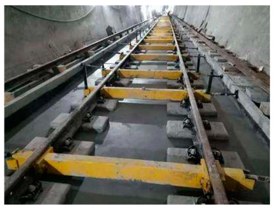
Figure 6.
LVT construction site in the tunnel.
In view of the fact that traditional LVT is used in low-axle load railways, and heavy-haul railway trains have heavy axles, it is difficult to meet safety requirements if the traditional structure is still used. Therefore, according to the characteristics of heavy-haul railways, the design optimization and calculation analysis of LVT are carried out to ensure the safety of LVT while ensuring its economic efficiency.
The lateral translation and torsional deformation of the rail relative to the sleeper under the action of the wheel-rail force will expand the gauge, change the geometry of the track, and cause track irregularities [16]. With the increase of speed, the increase of wheel-rail effect will aggravate the phenomenon of dynamic gauge expansion [17]. For LVT, under the effect of the lateral load of the train, the elastic support block will create a gap with the track bed, the support block will tilt laterally, the rail will shift and rotate laterally, and the gauge will expand, causing the rail to overturn [18,19,20].
Under the action of train load, how to control the lateral movement of the rail head is a very important content of the LVT structure design [21,22]. In addition to the reasonable selection of rubber boot stiffness, short sleeper size and fastener spacing, the size design of the LVT support block is also one of the important factors affecting the lateral movement of the rail head [23,24,25].
The supporting blocks of LVT are independent of each other and have poor integrity. If the embedding depth is insufficient, the rail displacement will be larger under the load of the train [26]. As the train speed and axle load increase, the dynamic geometric deviation of the track under driving conditions may exceed the limit, which will affect the safety of driving [27,28,29,30]. The most reasonable structure form should be considered when designing [31,32], but there are few theoretical studies on this aspect of LVT in the world.
Heavy-haul railways and other railways are also different in the transportation organization mode [33,34,35], so the LVT sleeper geometry should meet the transportation requirements of different speed levels and different axle load modes, while ensuring future axle load upgrades design. Therefore, this study conducted a preliminary analysis on whether LVT can be applied to heavy-haul railways from the perspective of judging the lateral deformation of the track.
1.2. Improved Plan of LVT Supporting Block
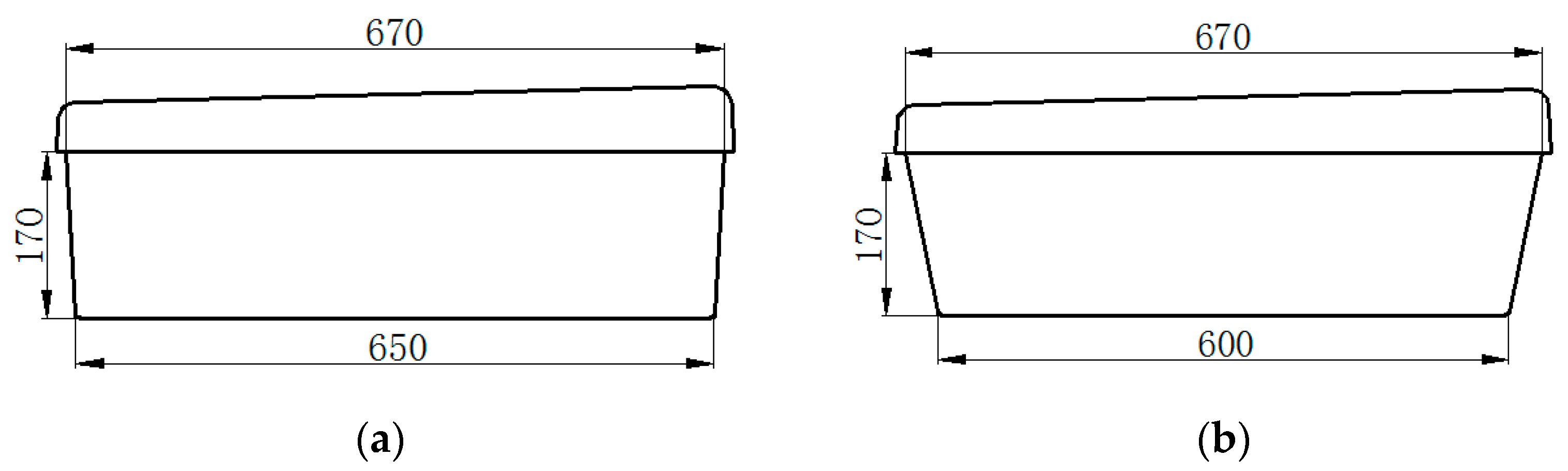
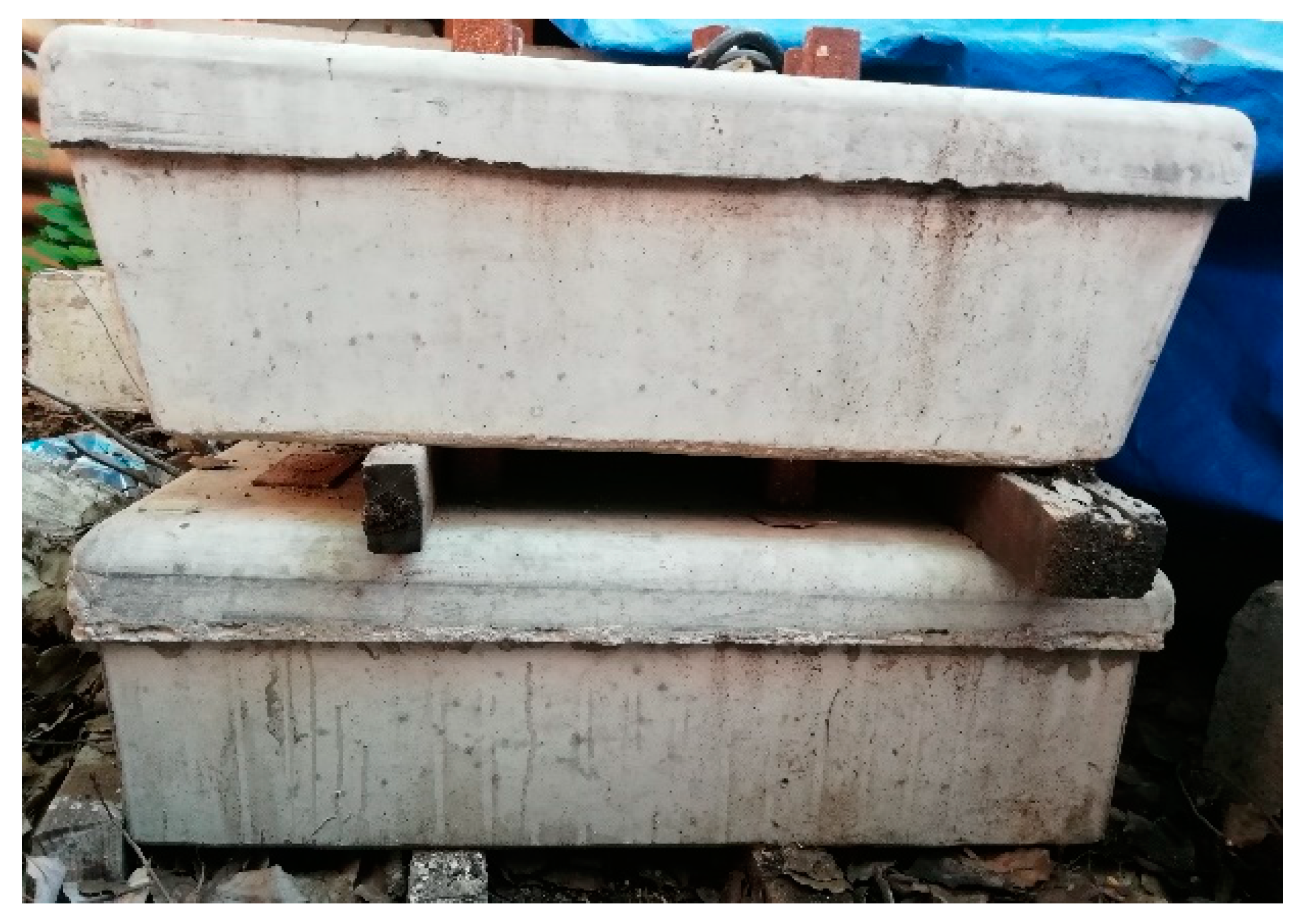
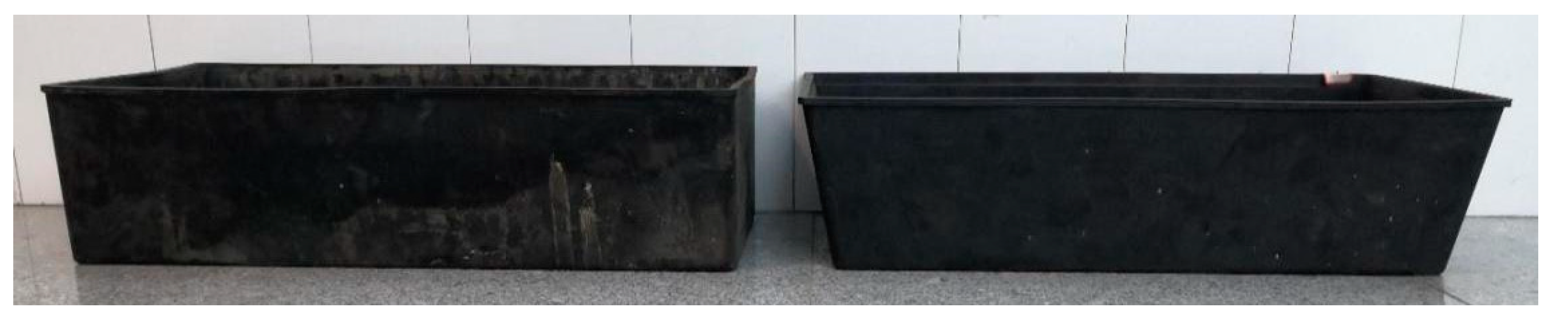
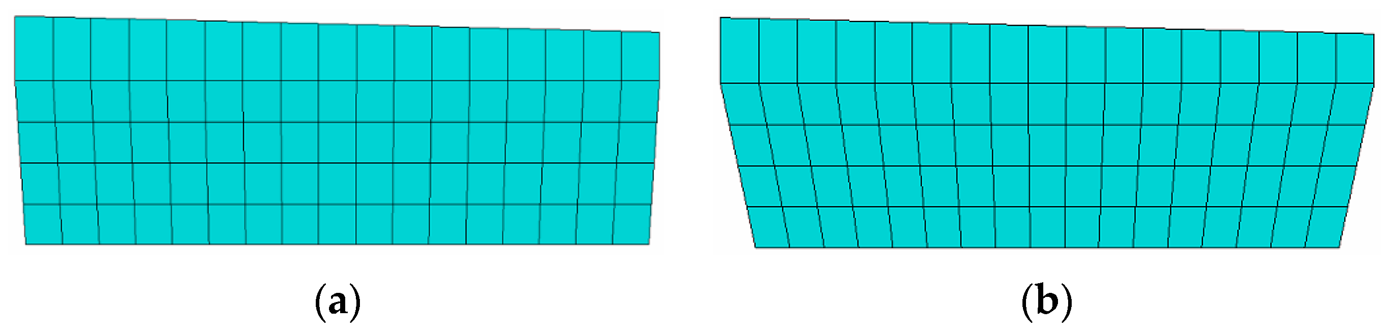
Through theoretical research and analysis, we improved the design of the supporting block structure in TLVT, and proposed a new type of supporting block structure. The improved design is to adjust the slope of the short side of the supporting block and increase the slope of the side. The bottom size is adjusted from the original length of 650 mm and width of 290 mm to length of 600 mm and width of 290 mm, so as to achieve the effect of better sharing the vertical force received by the support block to the overall track slab. The specific structural dimensions are shown in Figure 7a,b. The full-scale models of the two supporting blocks are shown in Figure 8, and rubber boots of corresponding sizes are used together (Figure 9). For the convenience of comparison and analysis, the original LVT will be referred to as “traditional LVT” (TLVT), and the improved design of LVT will be referred to as “improved LVT” (ILVT).
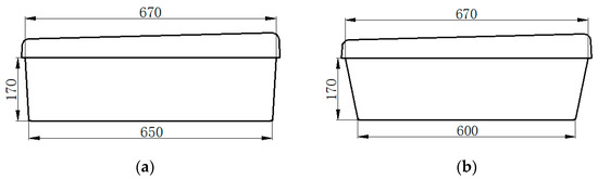
Figure 7.
Comparison of geometric shapes of TLVT and ILVT. (a) TLVT elastic support block size. (b) ILVT elastic support block size.

Figure 8.
Full-scale model of TLVT and ILVT supporting block.
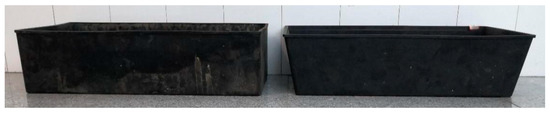
Figure 9.
TLVT and ILVT rubber boots.
1.3. Research Objectives
Since LVT is generally used for low axle load lines, it has outstanding advantages such as reasonable structure, low price, and easy maintenance. Therefore, this research considers the structural improvement of LVT so that it can meet the requirements of heavy-haul railways with large axle loads. The research objectives are as follows:
- (1)
- Through experiments and finite element research, explore the force of LVT under heavy-haul train load to judge whether it is suitable for heavy-haul railways;
- (2)
- By comparing the various indexes of ILVT with TLVT, to verify whether ILVT has a better ability to withstand larger loads than TLVT;
- (3)
- On the basis of experiments and finite element research, further size improvements are made to ILVT to ensure that it can meet the situation of larger axle load trains that may be operated in the future.
1.4. Research Methods
In view of the worldwide research methods of railway ballastless track structure, we plan to use the following methods to study the various mechanical properties of ILVT and compare it with TLVT to verify whether it can meet the requirements of heavy-haul railway lines:
- (1)
- By comparing the design drawings, the physical structure models of ILVT and TLVT are completely constructed and transported to the laboratory for experimental determination according to the load standard of the heavy-haul train. It is planned to use two different loading methods to test it. The content of the test includes: Vertical displacement, vertical load longitudinal sharing, gauge expansion, steel rail and supporting block turning angle, lateral load longitudinal sharing. By comparing the experimental results of ILVT and TLVT, the superiority of ILVT and its applicability in heavy-haul railways can be verified;
- (2)
- By comparing the design drawings and using the finite element method, the simulation models of ILVT and TLVT are completely constructed. By considering the train running through the LVT, the single-axle and double-axle loading methods are studied to study the force of the LVT track under 30t, 35t and 40t axle loads. After verifying its feasibility through experimental results, the displacement and stress contour maps of the two LVTs were studied as a basis to verify the superiority of ILVT and serve as the basis for subsequent dimensional design optimization.
- (3)
- In order to consider the possibility of increasing the axle load of the train in the future, the 40t axle load heavy-haul train is taken as the research object, and the dual axle load is used to carry out the lateral and vertical design load loading at the loading point with relatively poor force capacity. By increasing the length and width of the track bed slab, the LVT structure is optimized and analyzed, and various data indicators are compared to find the best design scheme suitable for 40t axle load trains, and then used in the design and planning of future LVT applications in heavy-haul railways, and use it in the design and planning of future LVT applications in heavy-haul railways.
1.5. Research Hypothesis
Compared with TLVT, the structure of ILVT’s supporting block increases the side slope, so that the bottom size is adjusted from the original length of 650 mm and width of 290 mm to length of 600 mm and width of 290 mm. Therefore, it is inferred that it should have a better ability to resist deformation, so the following research hypothesis is proposed:
- (1)
- Analyzed from the size, its effective vertical support area will increase to a certain extent, so as to achieve the effect of better sharing the vertical force received by the support block to the overall track slab. Therefore, it is envisaged that the ILVT design may reduce the vertical displacement of the rail and the supporting block, better control the sinking amount of the rail, and improve the driving safety of the LVT.
- (2)
- Since ILVT receives a lateral force, the angle with the lateral direction is smaller. Perhaps it is also possible to better transmit the load to the lower part of the track slab, resist the overturning of the support block, and thereby reduce the gauge expansion of the rail.
- (3)
- In view of ILVT’s stronger ability to support vertical and lateral forces, when subjected to load, its load point can support a larger load. Therefore, the vertical and lateral load transfer coefficients of ILVT should be greater than TLVT at the point of load application.
2. Full Scale Model Test
2.1. Overview of the Specimen
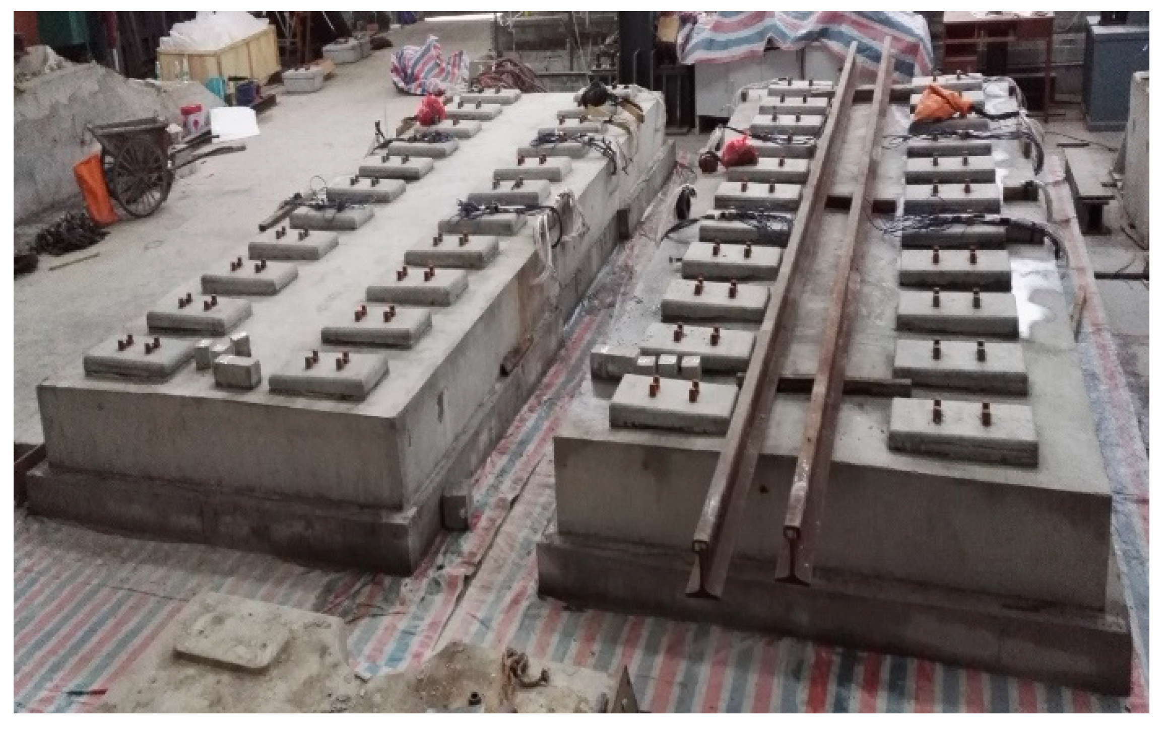
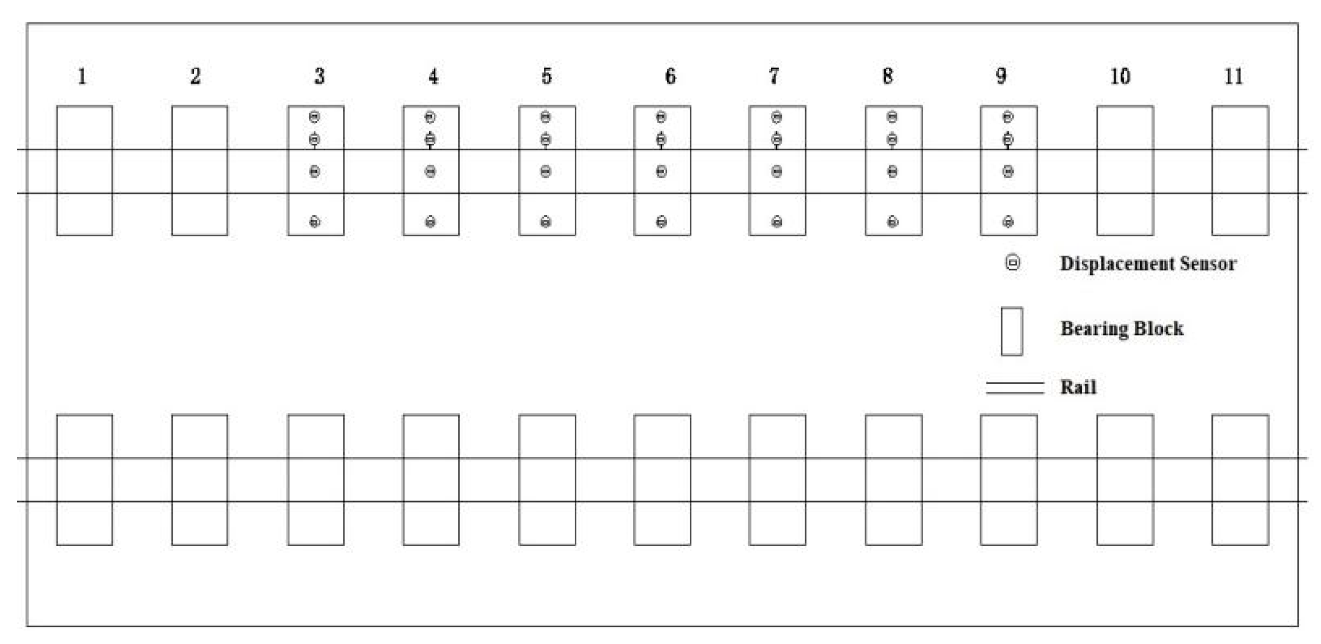
The test content includes testing the vertical displacement of the rail, the lateral displacement of the rail, the turning angle of the rail, the vertical displacement of the supporting block, the lateral displacement of the supporting block, and the turning angle of the supporting block. In the experiment, a long rail is used to apply vertical loads and lateral and vertical coupled loads to multiple supporting blocks, and a comparative analysis of the retaining ability of the two rail geometries is carried out.
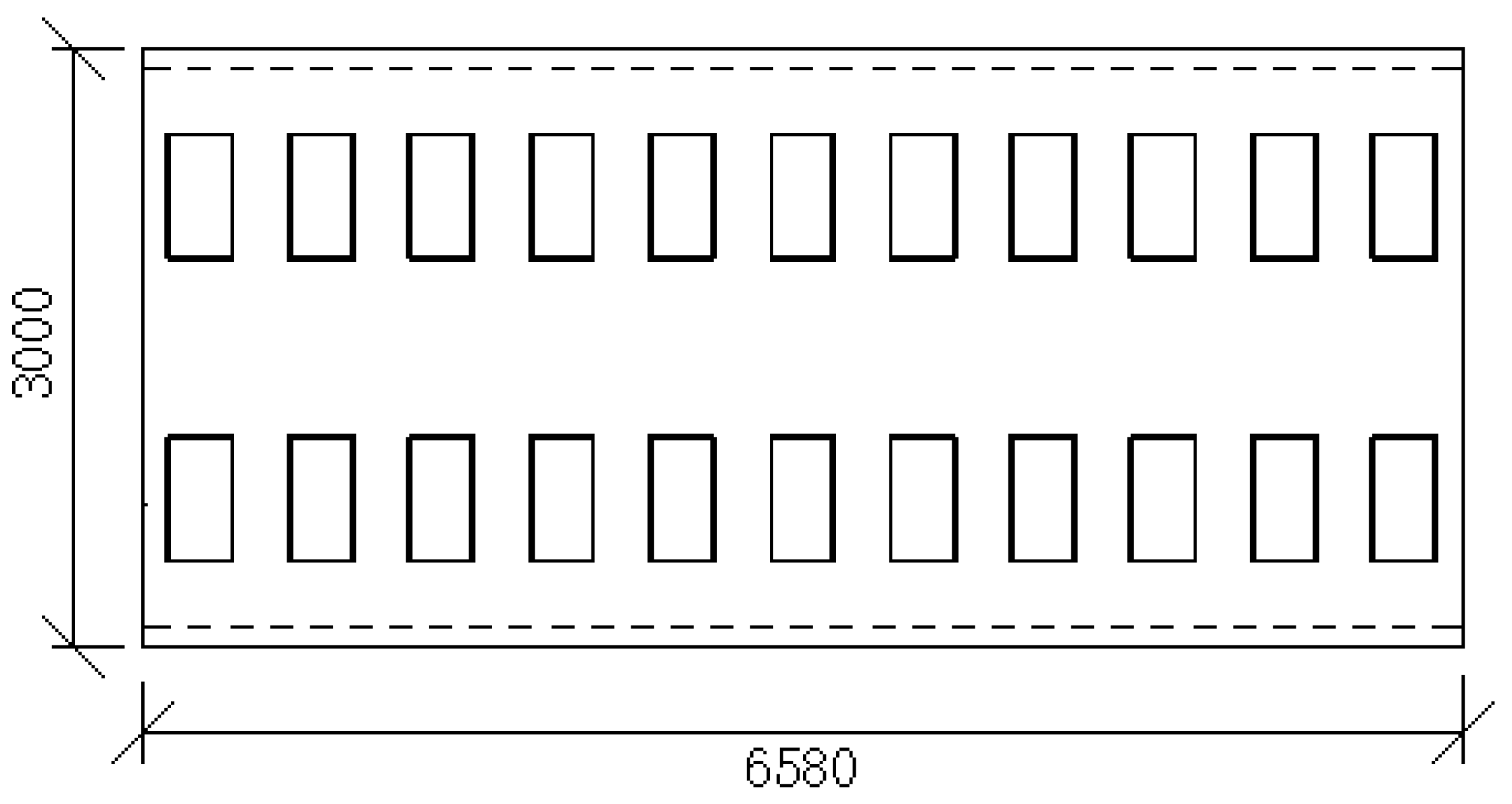
According to the LVT design data in the tunnel, the length of the test track model is designed according to 11 supporting blocks, which are numbered 1 to 11 starting from the slab end supporting block. The length of each track bed slab is 6.58 m, and 60 kg/m steel rail is laid. It is equipped with elastic VII type heavy-haul fasteners, and the fastener spacing is 600 mm [15]. The full-scale test model is shown in Figure 10, with TLVT on the left and ILVT on the right.
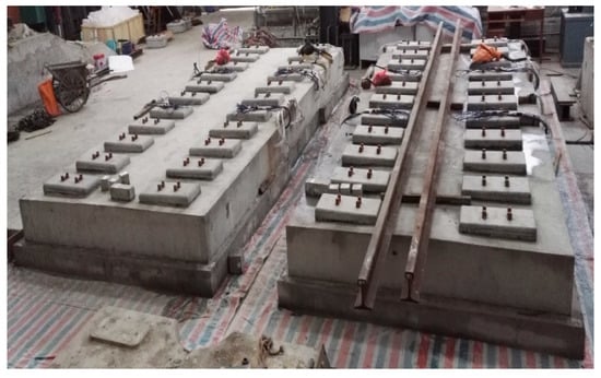
Figure 10.
Full-scale test model.
2.2. Experimental Conditions Setting
Condition 1: Applying vertical load to multiple supporting blocks through long steel rails to verify the vertical load bearing capacity of LVT.
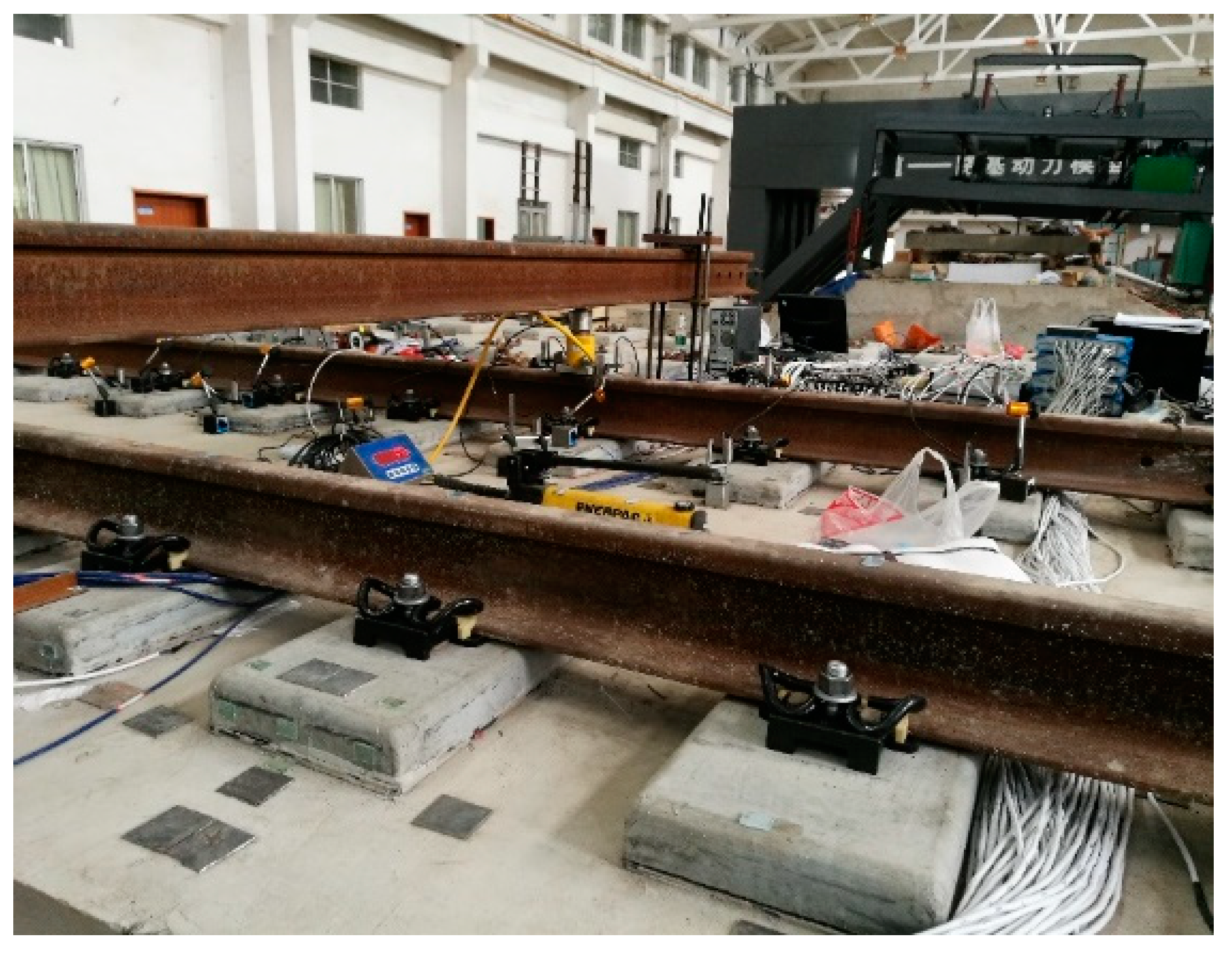
The supporting block is numbered 1 from one end of the track bed slab to 11 at the other end of the track bed slab, and load is applied at a constant speed to 225 kN at number 6 (Note: Based on the 30t axle heavy-haul train, 1.5 times the static wheel load is taken as 225 kN) [36], as shown in Figure 11. At the same time, a displacement meter is used to measure the vertical displacement of the supporting block numbered 3–9 and the vertical displacement of the rail. The measuring point arrangement is shown in Figure 12.

Figure 11.
Working condition one loading method.
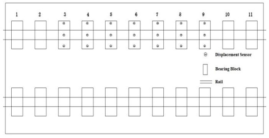
Figure 12.
Layout of measuring points for working condition 1.
Condition 2: Apply lateral and vertical coupled loads to multiple supporting blocks simultaneously through long rails to verify the mechanical properties of LVT under lateral loads.
Apply the load at a constant speed to 225 kN at No. 6, as shown in Figure 13. At the same time, the displacement meter is used to measure the lateral and vertical displacement of the supporting block numbered 3–9 and the lateral and vertical displacement of the steel rail. The measuring point arrangement is shown in Figure 14.
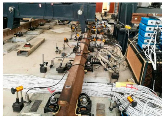
Figure 13.
Loading mode of working condition 2.
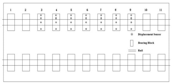
Figure 14.
Layout of the second measuring point in working condition.
2.3. Experimental Results and Data Analysis
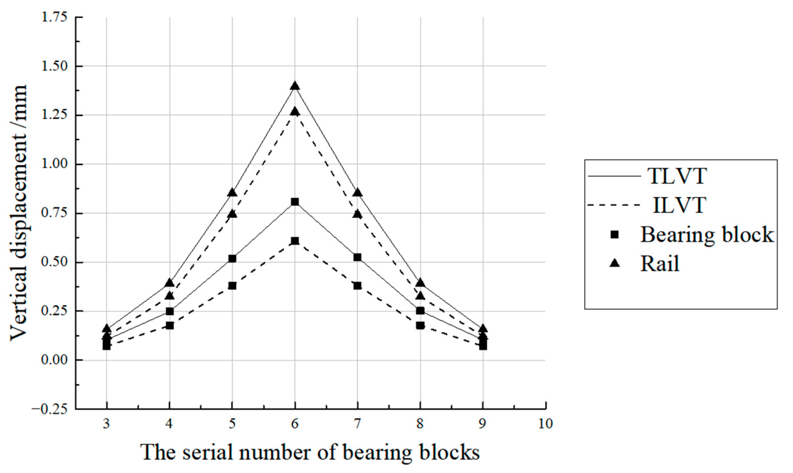
2.3.1. Vertical Displacement Analysis
In the loading mode of working condition 1, the vertical displacement test results of the rails and supporting blocks at the loading points 3–9 under the load of 225 kN are plotted as shown in Figure 15. At the same loading point, the vertical displacement of the ILVT rail and the supporting block is less than that of the TLVT. It can be seen from the data comparison and analysis that the ILVT design can reduce the vertical displacement of the rail and the supporting block, better control the track sinking, and improve the driving safety of LVT.
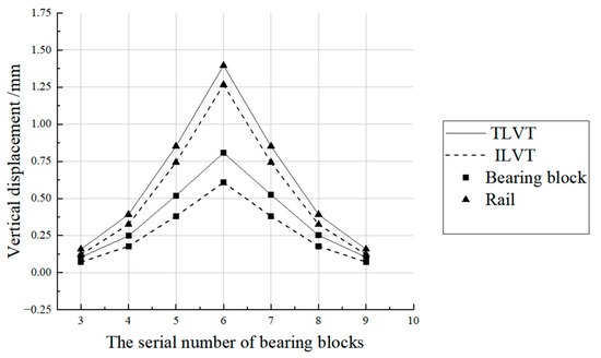
Figure 15.
The vertical displacement of the rail and bearing block in Working Condition 1.
2.3.2. Analysis of Longitudinal Load Sharing
When the No. 6 loading point is only subjected to a vertical load of 225 kN, the vertical displacement of the steel rail at the No. 3–9 loading point is measured to calculate the longitudinal load sharing law (Table 1). When the long rail only bears the vertical load, the vertical load sharing law of the two types of rail structures is basically the same. The load sharing value is the largest at the loading point, with TLVT being 32% and ILVT being 34%. The design of ILVT has little effect on the vertical load sharing, but because its sharing rate has been improved, it shows that the support block at the loading point has a stronger bearing capacity.

Table 1.
The law of longitudinal sharing of vertical load.
2.3.3. Analysis of Gauge Expansion
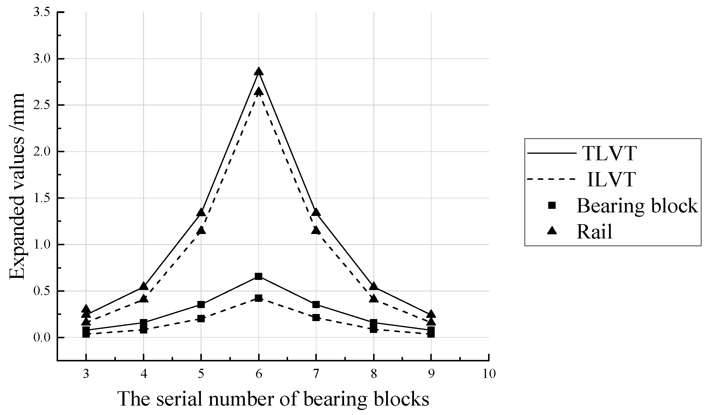
Under the loading mode of working condition 2, draw the test results of the lateral displacement of the rails and supporting blocks at the loading points 3–9 under a vertical load of 225 kN (Figure 16); among them, the expansion of the gauge is calculated from the lateral displacement of the rail heads on both sides, and the expansion of the lateral spacing between the supporting blocks is calculated from the lateral displacement of the supporting blocks on both sides. Part of the gauge expansion is caused by the overturning of the steel rail and the supporting block. According to the data comparison and analysis, the design of ILVT can reduce the expansion of the gauge and the lateral spacing of the supporting block, and improve the stability of the track structure.

Figure 16.
Expansion of lateral spacing of rail and bearing blocks in Working Condition 2.
2.3.4. Analysis of Turnover Angle of Rail and Support Block
It can be seen from Figure 16 that the expansion of the transverse distance between the rail and the supporting block is the largest at the load application point, and it gradually decreases along the longitudinal direction of the track structure to both sides. At the same loading point, the expansion of the lateral distance between the ILVT rail and the support block is less than that of the TLVT, so it is necessary to analyze the turning angle of the rail and the support block (Table 2).
Table 2.
Turnover angle of rail and support block.
According to the experimental data, under the same load at the same loading point, the turning angle of the rail and support block of ILVT is slightly smaller than that of TLVT (Table 2). The turning angle of the rail and support block of TLVT and ILVT is the largest at the load application point. The turning angle of ILVT is 4% smaller than that of TLVT, and the turning angle of ILVT support block is 13% smaller than that of TLVT. The design of ILVT improves the anti-overturning ability of rails and supporting blocks under lateral load to a certain extent.
2.3.5. Analysis of Transverse Load and Longitudinal Sharing
When loading 225 kN vertical load and 60 kN lateral load at No. 6 loading point in the slab, by measuring the lateral displacement of No. 3–9 rail heads, the law of lateral load and longitudinal sharing can be calculated (Table 3). When the long rail is subjected to 1.5 times the vertical static wheel load and 0.4 times the lateral static wheel load, the two types of track structures have basically the same transverse load and longitudinal sharing laws. The load sharing value at the loading point is the largest, 40% for TLVT and 44% for ILVT. The load sharing value of ILVT is slightly larger than that of TLVT.
Table 3.
Law of longitudinal sharing of transverse load.
3. LVT Finite Element Statics Analysis
Due to the limitations of test conditions, instruments and equipment, the indoor full-scale model test cannot meet all the working conditions required for comparison. Therefore, we use the finite element software to establish the LVT structure model, and compare the model values with the test results to verify the reliability of the model established by the finite element software.
3.1. Model Establishment
The finite element model of the LVT structural system includes rails, fasteners, support blocks, rubber boots, steel bars, track bed slabs and base slabs. For better verification with the full-scale model test, the established track structure parameters are the same as the full-scale test model.
- (1)
- Rail
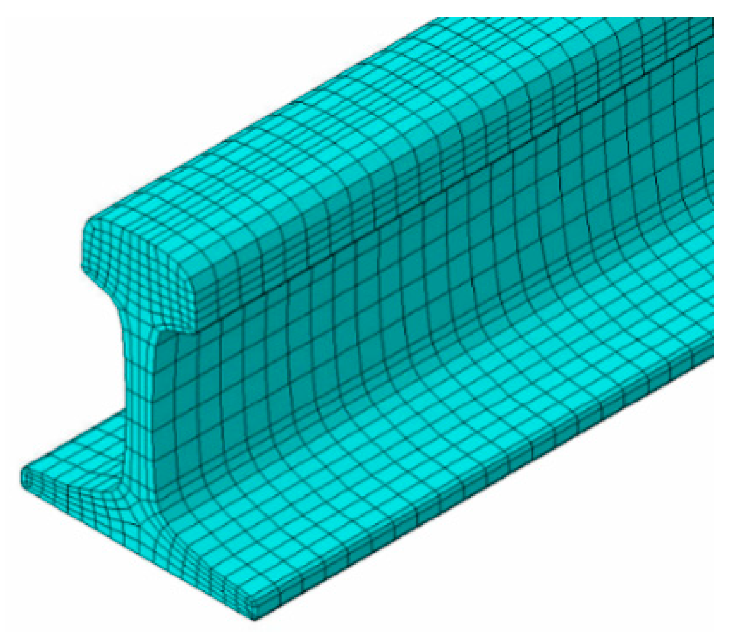
The rail is 60 kg/m with the modulus of elasticity of 210,000 MPa, Poisson’s ratio of 0.3, and density is 7800 kg/m3. To accurately measure the lateral displacement and flip angle of the rail, the solid element simulation was used and the rail section was drawn according to the actual size (Figure 17).
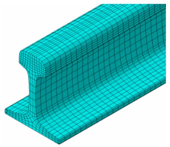
Figure 17.
Finite element model of rail.
- (2)
- Fasteners
The fasteners are elastic strip VII fasteners at a spacing is 600 mm. The fasteners were simulated using spring elements connecting the rail and the bearing block, while the rail was restrained by vertical and lateral and torsional stiffness. The vertical, lateral and longitudinal stiffness of the fastener is 140 kN/mm, 100 kN/mm, and 15 kN/mm respectively
- (3)
- Bearing block
The bearing block settings are designed with two sizes of TLVT and ILVT (Figure 18), and the parameters of C50 concrete are adopted. The elastic modulus is 34,500 MPa, the Poisson’s ratio is 0.2, and the density is 2500 kg/m3.
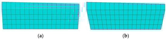
Figure 18.
Finite element model of TLVT and ILVT bearing block. (a) TLVT elastic support block. (b) ILVT elastic support block.
- (4)
- Elastic boots and the pad under the bearing block
Simulated by solid elements, the thickness of the elastic boots is 7 mm, and the thickness of the pad under the bearing block is 12 mm.
- (5)
- Track bed slab
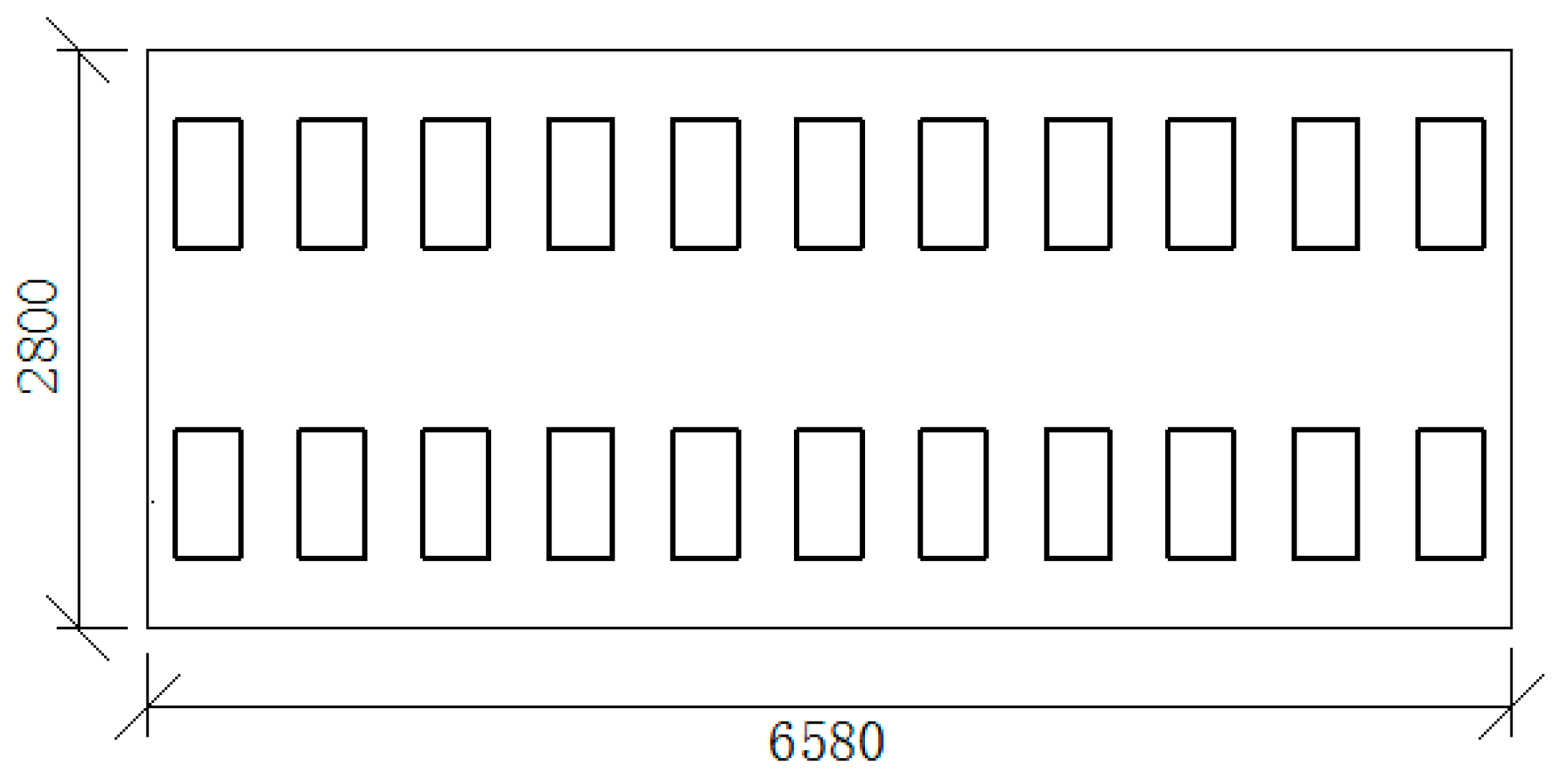
The track bed slab has a block structure with a width of 2800 mm, a thickness of 393 mm, and a length of 6580 mm. The C40 concrete parameters was adopted for the track bed slab with elastic modulus of 32,500 MPa, Poisson’s ratio of 0.2, and density of 2500 kg/m3 [15,16].
- (6)
- Reinforcing bars
The HRB400 grade reinforcing bars was adopted for the simulations. The reinforcing bars include 20 mm diameter upper longitudinal reinforcement, upper lateral reinforcement, lower longitudinal reinforcement and lower lateral reinforcement, 12 mm diameter bearing block stirrup and erecting reinforcement (Figure 19). The elastic modulus, poisson’s ration and density of the bar is 210,000 MPa, 0.3, 7800 kg/m3 respectively.
Figure 19.
Finite element model of reinforcing bars.
- (7)
- Base plate
The base plate is made of C20 concrete and has elastic modulus of 25,500 MPa, Poisson’s ratio of 0.2, and density of 2500 kg/m3 [18]. The support block and the rubber boots, the rubber boots and the track bed plate are in frictional contact, and the friction coefficient is taken as 0.3.
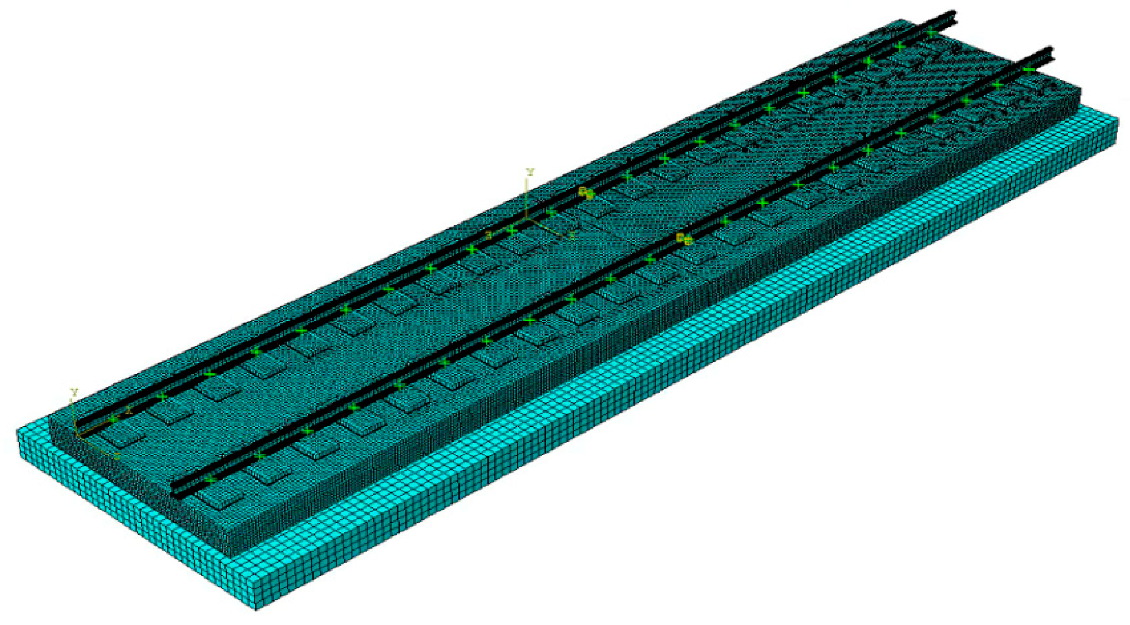
Combining the above parameters, a finite element calculation model for the long track of the LVT track is established (Figure 20).
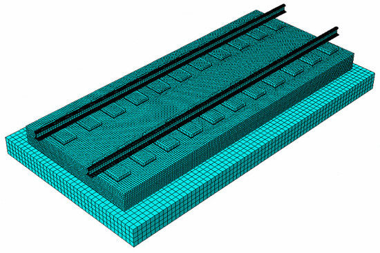
Figure 20.
LVT finite element model.
3.2. Finite Element Model Verification
In order to verify the reliability of the two LVT finite element models of TLVT and ILVT, we selected our static test geometry and static test mechanical properties to establish the finite element model, and compared and analyzed the corresponding test results. The calculation results are shown in the Table 4 and Table 5. Through the comparison test and the finite element model, the results of various indicators of the track structure are basically the same. The model can be applied to the research of LVT geometry and mechanical properties.
Table 4.
Comparative analysis of geometric shape from Finite element and Experiment.
Table 5.
Comparative analysis of mechanical performance research model and experiment.
4. Analysis of Mechanical Characteristics of LVT under Large Axle Load
The increase in axle load has a significant adverse effect on the performance of the track structure, and the axle load of heavy-haul railways is relatively large, so the vehicle load is the factor that has the greatest impact on the track structure [22]. In order to meet the needs of operating larger axle load trains in the future, we established a finite element model under the load of 30t, 35t, and 40t axle load. The applicability of the two LVT structures under a larger axle load was compared and analyzed, and the weak position of the track structure was found, and optimization suggestions were put forward.
4.1. Load Coupling Mode and Loading Basis
In order to better compare and analyze the geometry and mechanical properties of the slab and the end of the slab, we select two track bed slabs to establish a finite element model (Figure 21), and the expansion joint between the slabs is set to 20 mm.

Figure 21.
LVT finite element model with two slabs connected.
The track was loaded in two ways, single-axis and double-axis. The effects of the two loading modes on the performance analysis of the track structure were analyzed and compared. The single-axis load was applied at the center of the slab (position of No. 6 bearing block), the single-axis load of the track slab end was loaded at the position of No. 11 bearing block. The double-axis load at the center of the slab was loaded at the position of No. 6 and No. 9 bearing blocks, while the double-axis load was applied to the track slab end loaded at points 8 and 11.
- (1)
- Single-axis loading method
According to reference [36], the heavy-haul axle load of 30t and above with dynamic coefficient of 3.0, and lateral force coefficient of 0.8 was adopted. the. The vertical design load is 3 times the static wheel load, and the lateral design load is 0.8 times the static wheel load. The values of the three different axle loads acting on the single long rail are as follows:
- ①
- Taking the 30t axle heavy-haul train as the research object, the vertical force is 450 kN, and the lateral force is 120 kN;
- ②
- Taking the 35t axle heavy-haul train as the research object, the vertical force is 525 kN and the lateral force is 140 kN;
- ③
- Taking the 40t axle heavy-haul train as the research object, the vertical force is 600 kN and the lateral force is 160 kN.
- (2)
- Double-axis loading method
In the double-axis load analysis, the bogie is analyzed with the parameters of Chinese C96 train, and has wheelbase of 1860 mm. for the purpose of this study, a wheelbase value of 1800 mm was adopted to corresponds to the distance between the three bearing blocks [36].
4.2. Geometry Analysis under Double-Axis Load
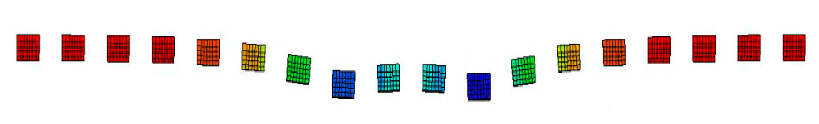
From the conclusions the vertical load distribution law and the lateral load distribution law, it can be deduced that the load influence range is mainly at the loading point and the distance between three adjacent bearing blocks. The wheelbase of the 30t axle-loaded train is 1860 mm, and the train loads between adjacent axles will superimpose each other. In this section, double-axle load is used for loading to analyze the influence of adjacent axle loads on a bogie. Taking the 30t axle heavy-haul train as the research object, the deformation cloud diagram of the rail and the bearing block under the double-axis load is shown in Figure 22 and Figure 23. It can be seen that the main longitudinal influence range of the load under the double-axis load is 10 bearing blocks.
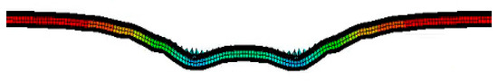
Figure 22.
Cloud diagram of rail deformation under double-axis load.
Figure 23.
Deformation cloud diagram of bearing block under double-axis load.
4.2.1. Vertical Displacement
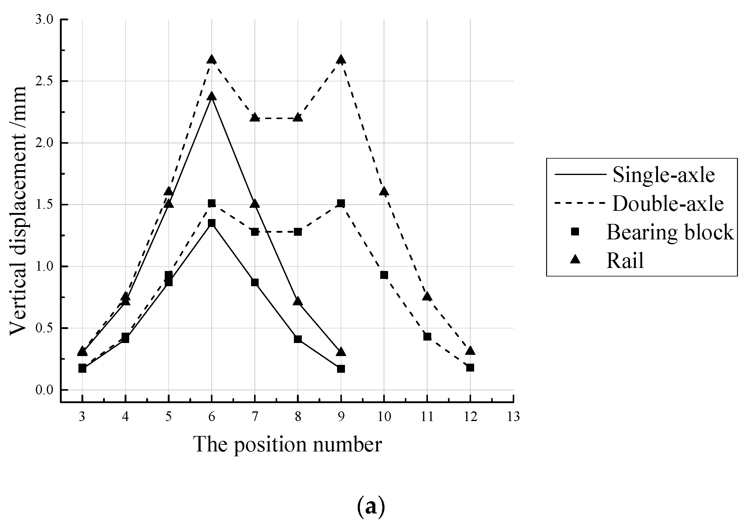
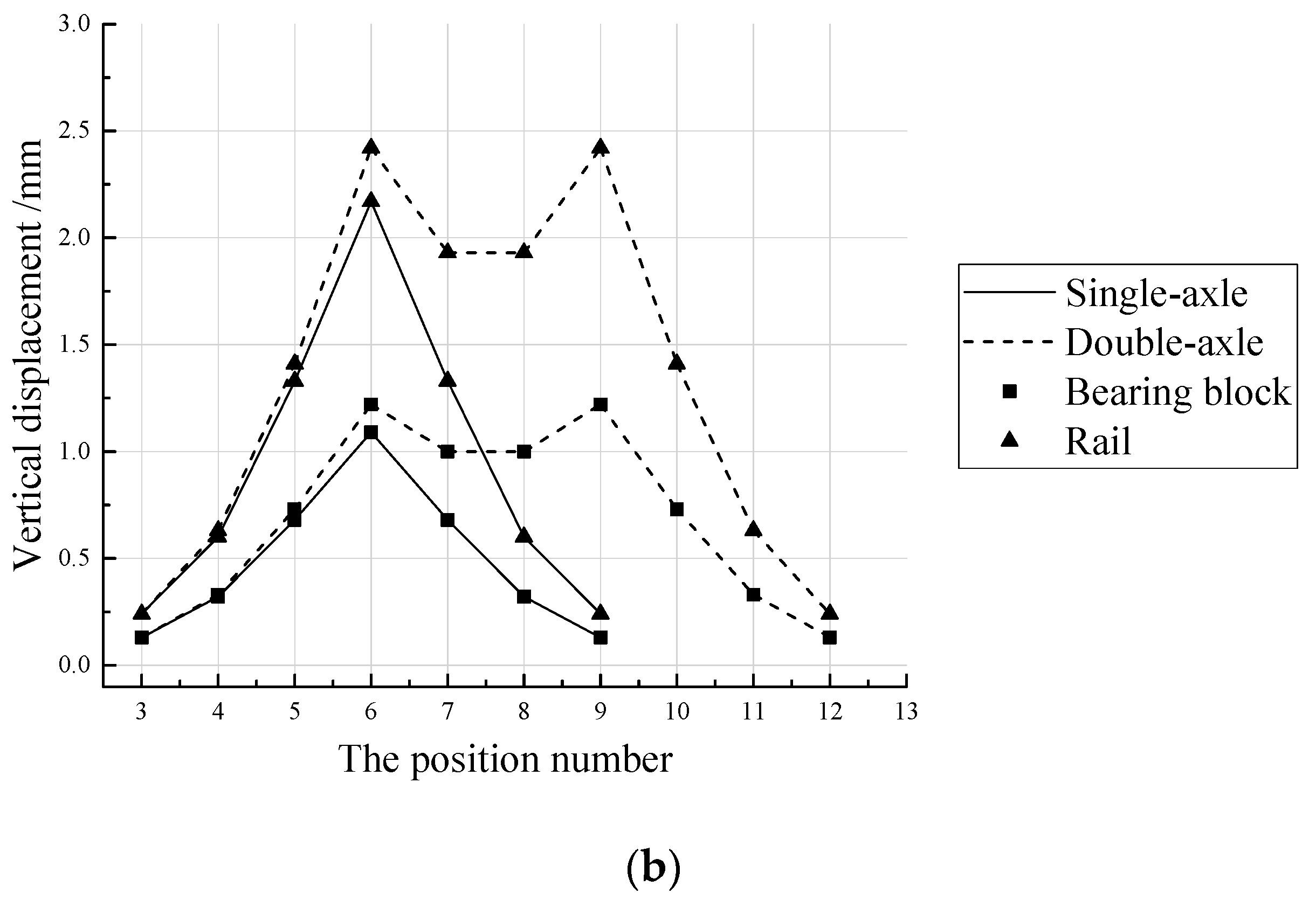
The plots of the vertical displacement curves of the rail and bearing blocks of the two track structures under single-axis and double-axis loads (Figure 24), which shows that the vertical displacement of rail and bearing block of ILVT at the same loading point is less than those of TLVT. At the loading point, the vertical displacement of the TLVT rail under double-axis load was recorded as 2.67 mm, which is more than 11% compared to single-axis load while that of ILVT is 2.42 mm, which is more than 10% compared to single-axis load. The vertical displacement of the bearing block of TLVT under double-axis load is 1.51 mm, which is more than 11% compared with single-axis load while that of the ILVT is 1.22 mm, which is more than 11% compared with single-axis load. However, the vertical displacement of the rail and bearing blocks of TLVT and ILVT under double-axis loading are all within the allowable deviation value.


Figure 24.
Vertical displacement of rail and bearing block under vertical load. (a) TLVT. (b) ILVT.
4.2.2. Deformation Analysis
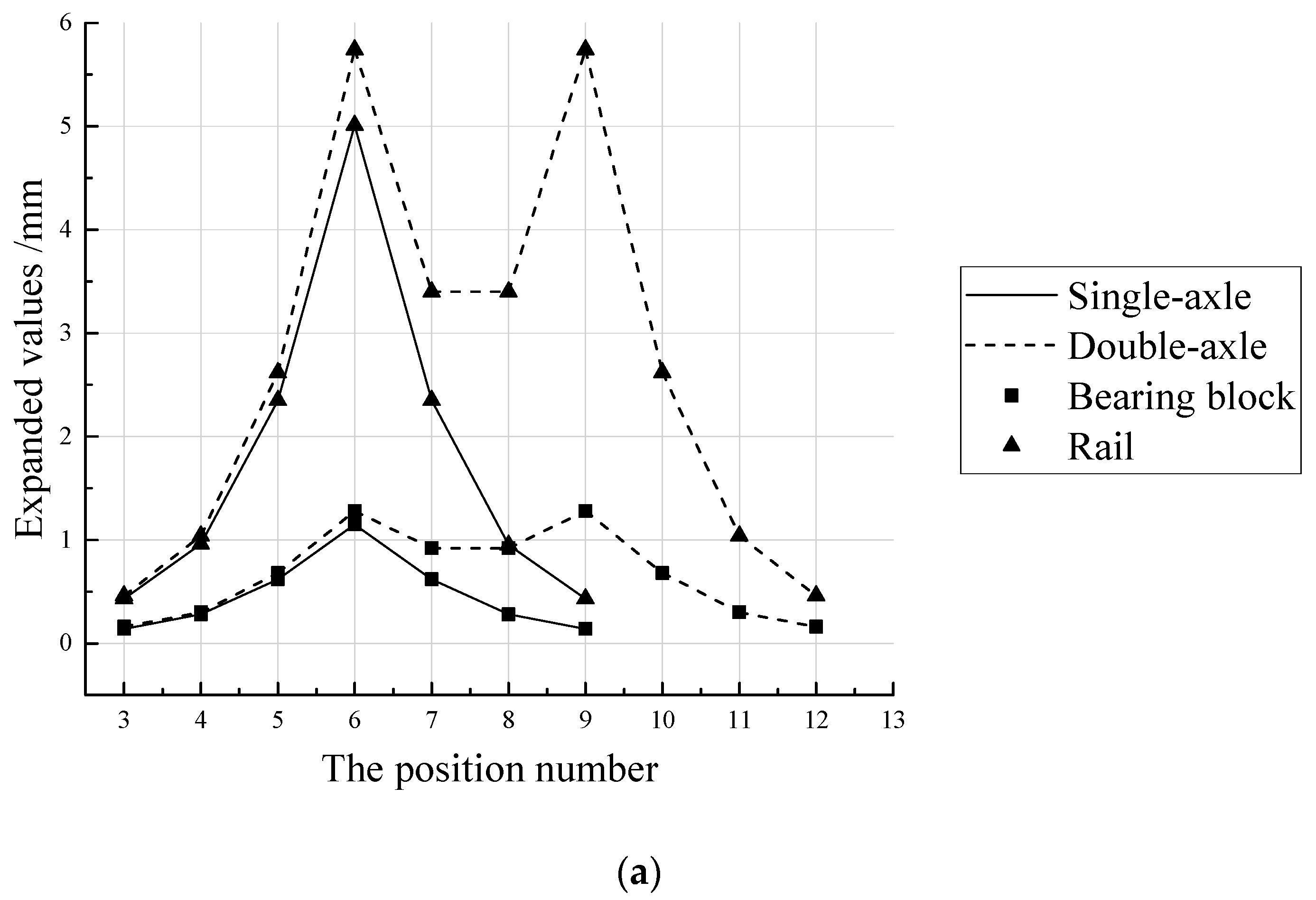
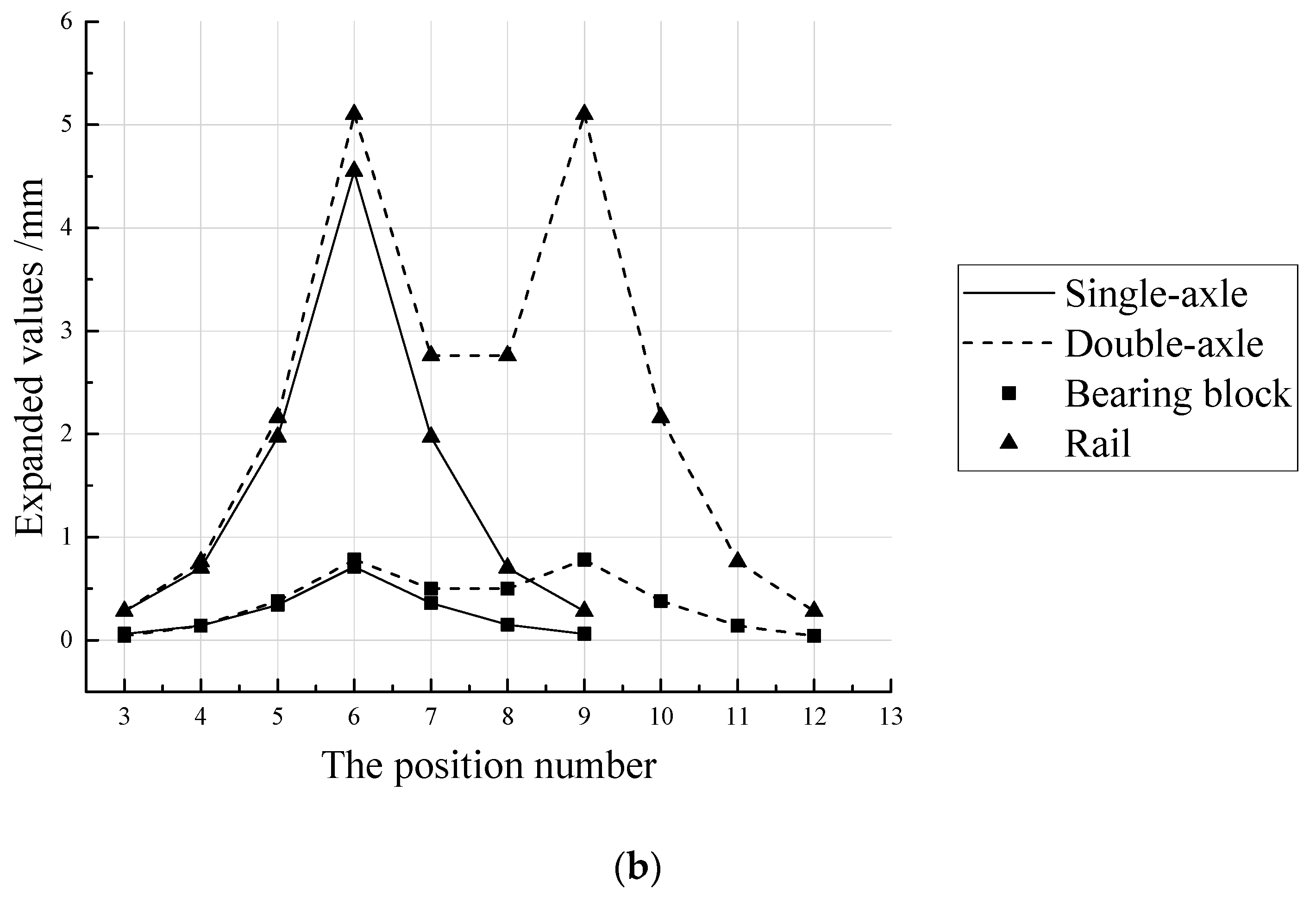
The Plots of the expansion curve of the lateral spacing of the rails and bearing blocks of the two track structures under single-axis and double-axis loads (Figure 25) shows that at the same point, the expansions of the rail and the bearing block of ILVT are less than that of the TLVT. At the loading point, the track gauge expansion of TLVT under double-axis load was recorded as 5.74 mm, which is more than 13% compared with single-axis load while that of ILVT is 5.1 mm, which is more than 11% compared with single-axis load. Under double-axis load, the expansion of the lateral spacing of the bearing blocks of TLVT was recorded as 1.28 mm, which is more than 10% compared with single-axis load while that of ILVT is 0.78 mm, which is more than 9% compared with single-axis load.

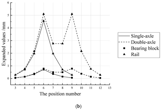
Figure 25.
The expansion of the lateral distance of the track gauge and the bearing blocks under the lateral and vertical coupled load. (a) TLVT. (b) ILVT.
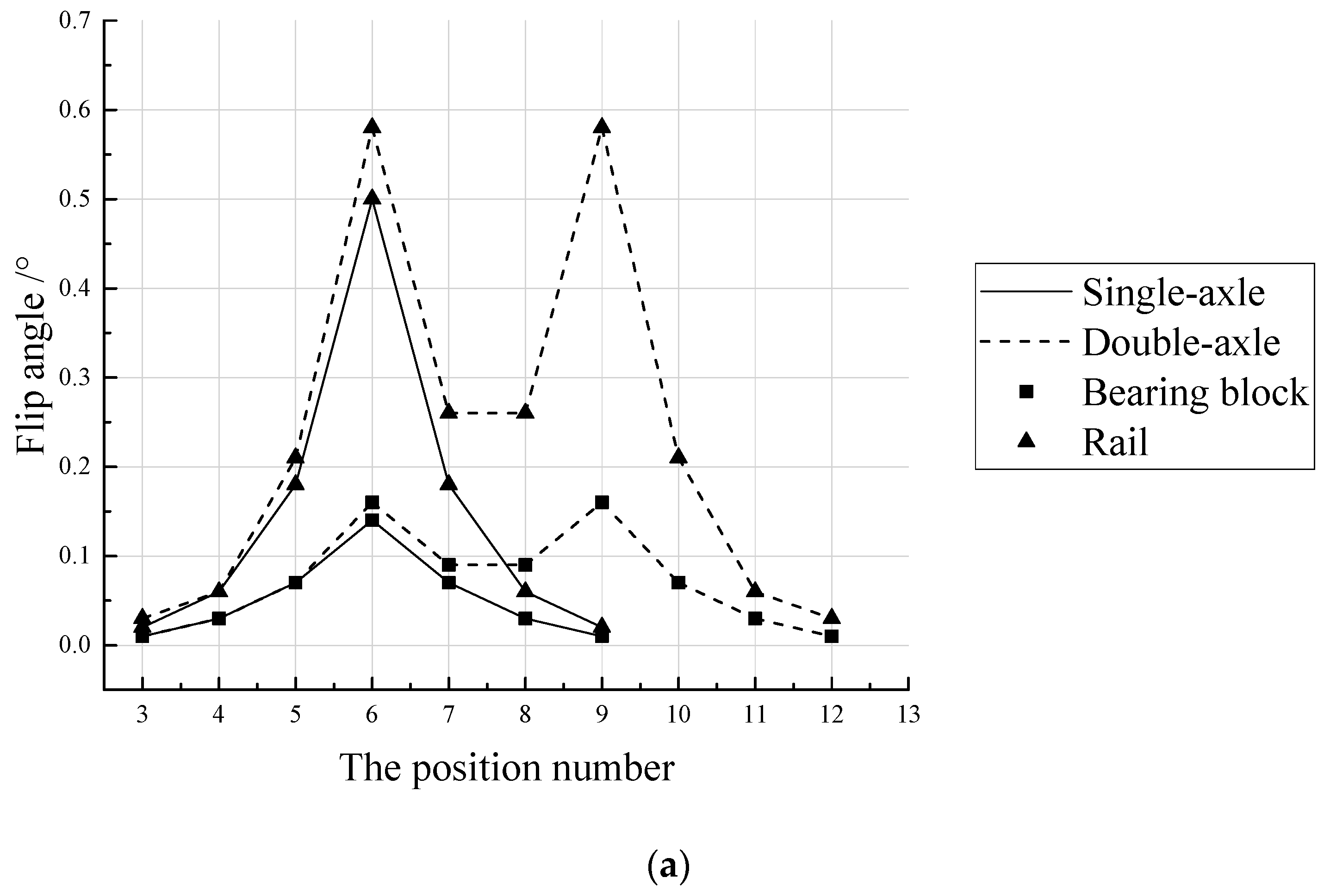
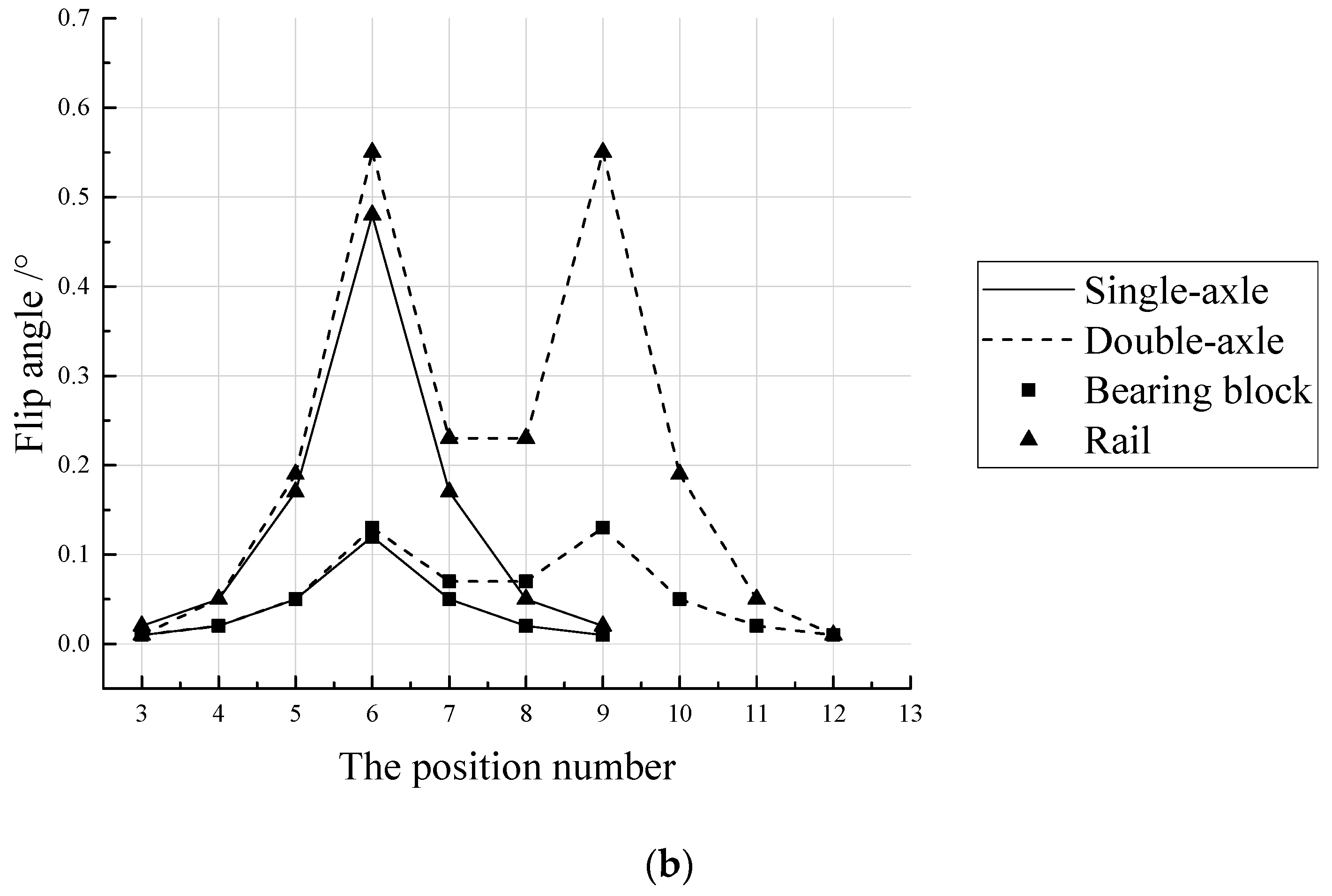
The plots of the the turning angle curves of the rail and bearing blocks of the two types of track structures under single-axis and double-axis loads (Figure 26) show that at the same loading point, the turning angle of the rail of TLVT reaches 0.58°, which is more than 14% compared to the single-axis load while that of the ILVT is 0.55°, which is more than 13% compared to the single-axis load. The turning angle of TLVT bearing block reaches 0.16°, which is more than 13% compared to the single-axis load while that of ILVT is 0.13°, which is more than 8% compared to the single-axis load.
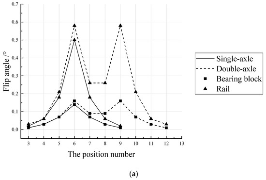

Figure 26.
Turning angle of rail and bearing block under lateral and vertical coupled load. (a) TLVT. (b) ILVT.
4.3. Analysis of Geometry under Axle Load of 30t and Above
Using double axles for loading, to apply the axle load values of 30t, 35t, 40t that is, the load acting at a single loading point of a single rail is vertical force 450 kN (30t axle load), 525 kN (35t axle load), 600 kN (40t axle load); lateral force: 120 kN (30t axle load), 140 kN (35t axle load), 160 kN (40t axle load), to both track types, the expansion, flip angle and displacement results at the same single-axis loading point are shown in Table 6.
Table 6.
Summary of geometric shape and position value under the axle load of 30t and above.
For the indicators in the table below for the same axle load, ILVT is less than TLVT. With reference to [37], it can be seen that:
- (1)
- The maximum vertical displacement of the rail is 4 mm, and the maximum vertical displacement of the support block is 2.5 mm. The vertical displacement of the TLVT and ILVT rails and the supporting block under the 40t axle load and biaxial load obey the recommended value.
- (2)
- The vertical displacement of TLVT rail is 3.51 mm, reaching 88% of the recommended value; the vertical displacement of ILVT rail is 3.19 mm, reaching 80% of the recommended value.
- (3)
- The vertical displacement of the TLVT support block is 1.96 mm, reaching 49% of the recommended value; the vertical displacement of the ILVT support block is 1.64 mm, reaching 41% of the recommended value.
4.4. Analysis of Mechanical Properties of Track Slab End under Axle Load of 30t and Above
According to the reference [15], the track structure is weak at the end of the slab, so the biaxial load is used for vertical and lateral loading at the loading points of No. 8 and No. 11 at the end of the slab. The load value is the same as that in Section 4.1. The stress cloud diagrams of the two track structures are shown in Figure 27, Figure 28, Figure 29 and Figure 30, which can be seen:
- (1)
- Great tensile stress was observed at approximately one-third of the bottom surface of the TLVT bearing block, whereas the maximum tensile stress on the bottom surface of the ILVT bearing block appears at the center under the action of vertical load. The maximum tensile stress position on the bottom surface of the bearing block is near the edge of the track bed under the action of lateral and vertical coupled loads.
- (2)
- The stress of the track bed slab mainly appears at the corner points of the bearing block, this implies that the unfavorable position of the TLVT track bed slab is mainly at the corner surface of the bearing block, and that of the ILVT track bed slab appears at the corner of the bearing block downward from the surface of the track bed slab which extends to the bottom of the groove and the short side of the end of the track slab.
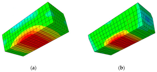
Figure 27.
Stress cloud diagram of bearing block under vertical load. (a) bearing block of TLV. (b) bearing block of ILVT.
Figure 27.
Stress cloud diagram of bearing block under vertical load. (a) bearing block of TLV. (b) bearing block of ILVT.

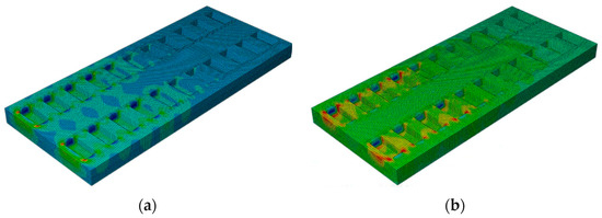
Figure 28.
Stress cloud diagram of track bed under vertical load. (a) Track bed of TLVT. (b) Track bed of ILVT.
Figure 28.
Stress cloud diagram of track bed under vertical load. (a) Track bed of TLVT. (b) Track bed of ILVT.

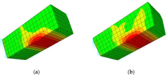
Figure 29.
Stress cloud diagram of bearing block under lateral and vertical coupled load. (a) bearing block of TLVT. (b) bearing block of ILVT.
Figure 29.
Stress cloud diagram of bearing block under lateral and vertical coupled load. (a) bearing block of TLVT. (b) bearing block of ILVT.

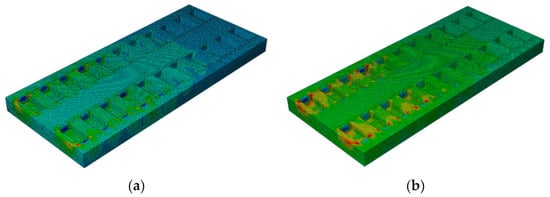
Figure 30.
Stress cloud diagram of track bed slab under lateral and vertical coupled load. (a) TLVT track slab. (b) ILVT track slab.
Figure 30.
Stress cloud diagram of track bed slab under lateral and vertical coupled load. (a) TLVT track slab. (b) ILVT track slab.

4.4.1. Stress Analysis under Vertical Load
According to the positions of the measuring points, the inner, middle, outer and bottom surfaces of the bearing block are marked as T1, T2, T3, and T4, respectively. The two track structures are are subjected to loading at points No. 8 and No. 11 under different axial loads (Table 7 and Table 8). From the knowledge of ultimate tensile strength of C40 and C50 concrete as 2.7 MPa and 3.1 MPa the results obtained for tensile strength test shows that under vertical loads of 30t, 35t, and 40t axle loads, the stress of the the two track bed slab and bearing block at similar loading points are within the ultimate tensile strength of concrete.
Table 7.
Stress value at No. 8 loading point under vertical load (MPa).
Table 8.
Stress value at No. 11 loading point under vertical load (MPa).
4.4.2. Stress Analysis under Lateral and Vertical Coupled Load
When the train is running, the rail will be subjected to lateral force, and the force response on the track structure is most unfavorable at this time. The stress of bearing blocks of the two track structures at the loading points of No. 8 and No. 11 under different axial loads and lateral and vertical coupled loads were also calculated (Table 9 and Table 10). Under the lateral and vertical coupled load of 30t, 35t, 40t axle load, the stress of the track bed slab and bearing block are within the ultimate tensile strength of concrete.
Table 9.
Stress value at No. 8 loading point under lateral and vertical coupled load (MPa).
Table 10.
Stress value at No. 11 loading point under lateral and vertical coupled load (MPa).
5. Research on Optimization Design of ILVT Structure
5.1. Scheme Optimization Design
The quest to accommodate larger axle load train drive through the ILVT in heavy-haul railway, based on the calculation results on the mechanical performance and full-scale test of the two track structures under the axle load of 30t and above, coupled with the quests to accommodate larger axle load train through LVT in tunnel, the optimization was suggested for the weakest position of the track structure. It can be seen from Section 4 that under the lateral and vertical design loads of the 30t and 35t axle heavy-haul train, the maximum stress of the track bed slabs and bearing blocks of the two track structures are within the ultimate tensile strength of concrete. Therefore, we took the 40t axle heavy-haul train as the research object, and used the double-axis load to apply the lateral and vertical design load at the No. 8 and No. 11 loading points of the track slab end in order to optimize geometric dimension of the track bed slab. The original dimensions and optimized design of the track bed are shown in Figure 31, Figure 32 and Figure 33.
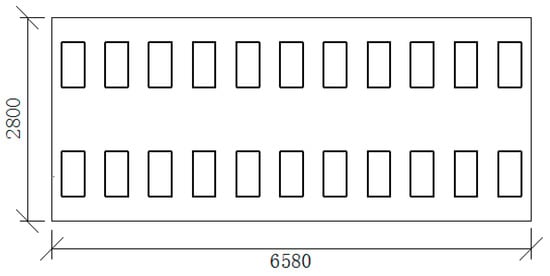
Figure 31.
Original size of track bed.
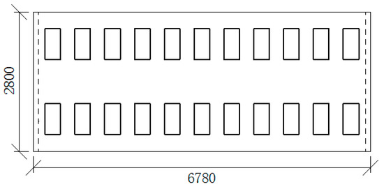
Figure 32.
Optimal design of track bed slab length.
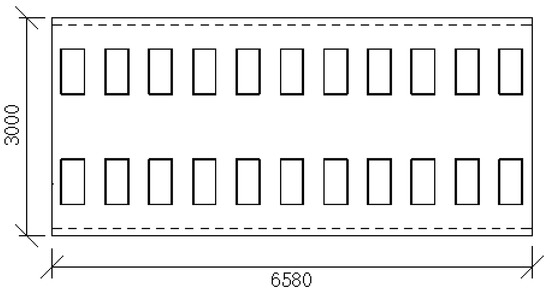
Figure 33.
Optimized design of track bed width.
5.2. Comparison of Mechanics of Different Geometrical Dimensions of the Track Structures
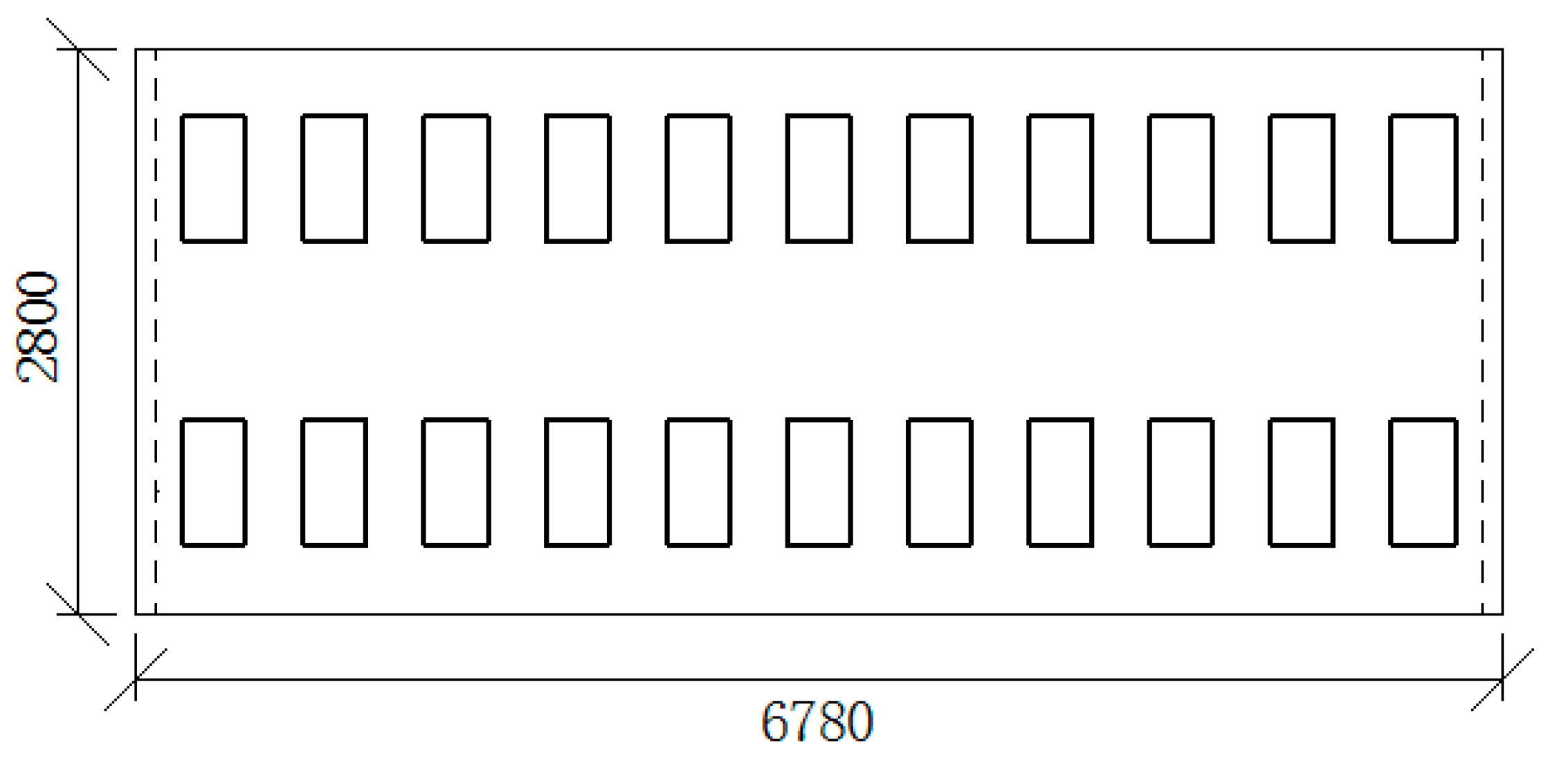
The initial dimensions of the track bed slabs of the two track structures are t similarwith a length of 6580 mm and width of 2800 mm. The optimizations of the length and width of the two track slabs are as follows:
5.2.1. Length Optimization
The length of the track bed slab was optimized by considering six sizes of the track bed end as follows; 20 mm, 40 mm, 60 mm, 80 mm, 100 mm and 120 mm (Figure 32). The length of the track bed slab was increased by 100 mm as an example, so that the track bed slab is 6780 mm long and 2800 mm wide. The inside, the middle the outside parts of the bearing block are marked as T1, T2, and T3 respectively. The stress of T1, T2 and T3 at loading point No. 11 of the six sizes were also calculated (Table 11 and Table 12).
Table 11.
Lengthen TLVT in the longitudinal direction (MPa).
Table 12.
Lengthen ILVT in the longitudinal direction (MPa).
5.2.2. Width Optimization
Similar to the sizes considered for the optimization of the length of the track bed slab, the optimization of the width of the track bed slab was attempted by considering six different sizes increment as follows: 20 mm, 40 mm, 60 mm, 80 mm, 100 mm and 120 mm. By increasing the track bed slab width by 100 mm (Figure 33), the track slab length becomes 6580 mm, and width becomes 3000 mm. The stress of T1, T2 and T3 at the loading points of No. 8 and No. 11 of six sizes were calculated (Table 13 and Table 14).
It can be seen that widening the width of the track bed will affect the end and internal force performance of the track bed at the same time. As the width of the track bed increases, the stress gradually decreases. When the length increases to 40 mm, the change tends to be gentle. At this time, the stress at T1 and T2 drops to 77% and 85% of the original size, and the stress at T3 changes less. At the load point of No. 11, the stress at T1 position gradually decreases with the increase in the width of the track bed slab, and the stress at other positions changes little.
Table 13.
Widen TLVT in the lateral direction (MPa).
Table 13.
Widen TLVT in the lateral direction (MPa).
| Position | Original Size | 20 mm | 40 mm | 60 mm | 80 mm | 100 mm | 120 mm | |
|---|---|---|---|---|---|---|---|---|
| Loading point 8 | T1 | 2.53 | 2.23 | 1.99 | 1.94 | 1.90 | 1.86 | 1.82 |
| T2 | 0.84 | 0.78 | 0.72 | 0.71 | 0.70 | 0.70 | 0.70 | |
| T3 | 0.54 | 0.54 | 0.54 | 0.52 | 0.50 | 0.49 | 0.48 | |
| Loading point 11 | T1 | 3.06 | 3.00 | 2.96 | 2.91 | 2.89 | 2.86 | 2.83 |
| T2 | 1.50 | 1.50 | 1.50 | 1.50 | 1.50 | 1.50 | 1.50 | |
| T3 | 2.20 | 2.21 | 2.21 | 2.19 | 2.16 | 2.14 | 2.11 | |
Table 14.
Widen ILVT in the lateral direction (MPa).
Table 14.
Widen ILVT in the lateral direction (MPa).
| Position | Original Size | 20 mm | 40 mm | 60 mm | 80 mm | 100 mm | 120 mm | |
|---|---|---|---|---|---|---|---|---|
| Loading point 8 | T1 | 2.52 | 2.34 | 2.21 | 2.14 | 2.11 | 2.06 | 2.02 |
| T2 | 1.09 | 1.10 | 1.11 | 1.10 | 1.10 | 1.09 | 1.09 | |
| T3 | 1.15 | 1.09 | 1.05 | 1.03 | 1.02 | 1.01 | 1.01 | |
| Loading point 11 | T1 | 2.65 | 2.61 | 2.57 | 2.53 | 2.49 | 2.46 | 2.42 |
| T2 | 1.40 | 1.47 | 1.54 | 1.54 | 1.55 | 1.55 | 1.55 | |
| T3 | 2.09 | 2.04 | 2.00 | 1.97 | 1.96 | 1.95 | 1.95 | |
6. Discussion
By carrying out the analysis and optimization of the LVT track structure under the load of a heavy-haul train, we have completed the research goal. According to the analysis of experiments and finite element data, it is not difficult to see that ILVT has better mechanical properties than TLVT. When ILVT is subjected to the same load, the ILVT design can reduce the vertical displacement of the rail and the supporting block, better control the sinking amount of the track, and improve the driving safety of LVT. As the load sharing rate of LVT at the loading point has been improved, it shows that the supporting block at the loading point has a stronger bearing capacity.
Because part of the gauge expansion is caused by the overturning of the steel rail and the supporting block. For this type of track structure, as the axle load increases, the various indicators of the track structure response show a linear increase trend, and the maximum displacement of the rail is 2.67 mm. Comparing the test results in the literature [38], the displacement is less than the test value when the 39t axle load vehicle passes, and it can be considered that the vertical displacement of the rail meets the requirements. It can be seen from the data comparison and analysis that the design of ILVT can reduce the expansion of the gauge and the lateral spacing of the supporting block, and also improve the anti-turning ability of the rail and the supporting block under the lateral load to a certain extent, and improve the stability of the track structure.
According to reference [37], the general railway track dynamic quality tolerance management value specifies the gauge tolerance value of +8 mm, and the track static geometric dimension tolerance management value specifies the gauge tolerance value of +6 mm. Under the action of 40t axle load and double axle load, the gauge expansion of TLVT and ILVT did not exceed the management value of dynamic quality tolerance of track, but both exceeded the management value of static geometric dimension tolerance.
Calculated from the data in Table 6, the gauge expansion of TLVT reaches the static management value when the axle load is 31.4t; the gauge expansion of ILVT reaches the static management value when the axle load is 35.2t. The comparison shows that ILVT track has better geometrical position retention capability than TLVT when running a 40t axle load train, and it can be better adapted to the operation of larger axle load trains in terms of geometrical position.
According to the stress cloud diagrams of the two LVT structures (Figure 27, Figure 28, Figure 29 and Figure 30), it can be seen that great tensile stress was observed at approximately one-third of the bottom surface of the TLVT bearing block, whereas the maximum tensile stress on the bottom surface of the ILVT bearing block appears at the center under the action of vertical load. The maximum tensile stress position on the bottom surface of the bearing block is near the edge of the track bed under the action of lateral and vertical coupled loads. The stress of the track bed slab mainly appears at the corner points of the bearing block, this implies that the unfavorable position of the TLVT track bed slab is mainly at the corner surface of the bearing block, and that of the ILVT track bed slab appears at the corner of the bearing block downward from the surface of the track bed slab that extends to the bottom of the groove and the short side of the end of the track slab. Therefore, these positions should be the focus of LVT structure optimization at 40t. It can also be seen that although the two structures are similar, their force characteristics are significantly different.
Under the vertical load of 40t axle load, the stress at the bottom of the supporting block at the point of load application reaches the ultimate tensile strength of concrete. At the point of load 11, the stresses at T1, T2, T3, and T4 of TLVT reach 89%, 82%, 56%, and 90% of the ultimate tensile strength of concrete, respectively, the stresses at T1, T2, T3, and T4 of ILVT reach 77%, 62%, 62%, and 99% of the ultimate tensile strength of concrete, respectively.
Under the lateral and vertical coupled load of 40t axle load, the stress at the bottom of the supporting block at the load application point of the two track structures exceeded the ultimate tensile strength of concrete, with TLVT exceeding 15% and ILVT exceeding 14%. At No. 8 load point, the maximum stress of TLVT and ILVT track bed slabs reached 94% and 93% of the ultimate tensile strength of concrete, respectively. At the load point of No. 11, the track bed slab stress is the largest at the T1 position, TLVT exceeds the ultimate tensile strength of concrete by 14%, and ILVT reaches 98% of the ultimate tensile strength of concrete. T3 is also the weak position of the track bed slab, and the stresses at TLVT and ILVTT3 reach 81% and 77% of the ultimate tensile strength of concrete, respectively. The above-mentioned scenes all show that ILVT has a better structure, which can further delay the cracking of the structure.
Under the lateral and vertical design loads of the 30t and 35t heavy-haul train for the two types of track structures, the maximum stress of the track bed slab and the bearing block are within the ultimate tensile strength of the concrete.
However, under the lateral and vertical design loads of the 40t axle heavy-haul train, the maximum stress of the TLVT track bed slab exceeds the ultimate tensile strength of concrete, with a stress on the bottom surface of the bearing blocks of the two track structures of 3.5 MPa. Therefore, the following methods are advised to optimize the design of the track structure to better application to the operation of 40t axle heavy-haul train:
- (1)
- By lengthening the track bed by 50 mm and above, the maximum stress of the track bed can be reduced.
- (2)
- By increasing the concrete grade of the track bed slab to C50 concrete, the mechanical performance of the track bed slab can be improved.
- (3)
- By adopting C60 concrete and arranging steel bars at the bottom, the stress performance of LVT can be improved.
7. Conclusions
Taking the LVT in the heavy-haul railway tunnel as the research object, based on the two LVT full-scale test models of TLVT and ILVT, the geometric shape retention ability and mechanical properties of the LVT are studied. Based on this, the length and width of the track slab are optimized, and the following conclusions are drawn:
- (1)
- Compared with TLVT, the design of ILVT can reduce the vertical displacement of the rail and support block, better control the amount of track sinking, and improve the driving safety of LVT. At the same time, ILVT also improves the anti-overturning ability of the rail and support block under lateral load, reduces the expansion of the gauge and the lateral spacing of the support block, improves the stability of the track structure, and is more suitable for heavy-haul railways.
- (2)
- When conducting experiments and finite element analysis, it can be clearly found that under the action of vertical load, the longitudinal load sharing value of ILVT at the loading point is significantly greater than that of TLVT. It can be seen that the improvement of the short side slope of the support block can indeed increase the efficiency of the structure at the loading point in the load sharing of the wheel load. From another perspective, it reflects that the ILVT has a better load bearing capacity.
- (3)
- Combining relevant specifications, it is calculated that TLVT reaches the static management value when the axle load is 31.4t; the ILVT reaches the static management value when the axle load is 35.2t. It can be seen that ILVT has better resistance to gauge changes and can be applied to heavy-haul railway lines with larger axle loads.
- (4)
- The unfavorable position of the TLVT track bed is mainly at the surface of the support block corner point, while the unfavorable position of the ILVT track bed occurs at the corner of the support block extending from the surface of the track bed to the bottom of the groove and the short side of the slab end. It can be seen that although the two structures are similar, their force characteristics are significantly different.
- (5)
- Research shows that the LVT structure, which is generally considered to be only used for low axle loads, can indeed meet the operation of heavy-haul trains with axle loads of 35t and below. However, considering the possible operation of the 40t axle-loaded heavy-haul train in the future, it is necessary to appropriately lengthen the longitudinal length of the structure, increase the reinforcement and increase the strength of the structural material to ensure its possible future force performance.
Author Contributions
Conceptualization, Z.Z. and G.P.; methodology, W.G.; software, G.P.; validation, Z.Z., G.P. and X.H.; formal analysis, W.W.; investigation, J.H.; resources, S.L.; data curation, A.A.S.; writing—original draft preparation, Z.Z.; writing—review and editing, Y.Y.; visualization, Z.Z.; supervision, Z.Z.; project administration, X.D.; funding acquisition, X.D.; All authors have read and agreed to the published version of the manuscript.
Funding
This research was funded by the Open Fund Project of State Key Laboratory of High-speed Railway Track Technology, grant number [2021K002]; Hunan Provincial Natural Science Foundation Project, grant number [2019JJ40384]; Scientific Research Test Project of China Railway Corporation, grant number [SY2016G001]; the Fundamental Research Funds for the Central Universities of Central South University, grant number [2019zzts873].
Institutional Review Board Statement
Not applicable.
Informed Consent Statement
Not applicable.
Data Availability Statement
Experimental data has been presented in the context.
Conflicts of Interest
The authors declare no conflict of interest. The authors declare no potential conflicts of interest with respect to the research, authorship, and/or publication of this article.
References
- Sampaio, R.; Chan, T. Modal parameters identification of heavy-haul railway RC bridges—Experience acquired. Struct. Monit. Maint. 2015, 2, 1–18. [Google Scholar] [CrossRef]
- Hart, J.M.; Fern, L.; Molina, O.; Resendiz, E.; Edwards, J.R.; Ahuja, N.; Barkan, C.P. Development of a Machine Vision System for the Inspection of Heavy-Haul Railway Turnout and Track Components; CiteSeerX: State College, PA, USA, 2011. [Google Scholar]
- Cleante, V.G. Effects of Railway Track Vibration Induced by Passing Trains on an Energy Harvesting Device. 2015. Available online: https://repositorio.unesp.br/handle/11449/128026 (accessed on 24 July 2015).
- Busatta, F.; Moyo, P. Vibration Monitoring of a Large Scale heavy-haul Railway Viaduct. In MATEC Web of Conferences; EDP Sciences: Ulis, France, 2015; Volume 24, p. 04007. [Google Scholar]
- Kumar, S. Vibration in operating heavy-haul trucks in overburden mining. Appl. Ergon. 2004, 35, 509–520. [Google Scholar] [CrossRef] [PubMed]
- Zhang, D.; Zhai, W.; Wang, K. Dynamic interaction between heavy-haul train and track structure due to increasing axle load. Aust. J. Struct. Eng. 2017, 8, 190–203. [Google Scholar] [CrossRef]
- Zhong, W.; Hu, J.J.; Shen, P.; Wang, C.Y.; Lius, Q.Y. Experimental investigation between rolling contact fatigue and wear of high-speed and heavy-haul railway and selection of rail material. Wear 2011, 271, 2485–2493. [Google Scholar] [CrossRef]
- Zhao, X.; Yang, J.; An, B.; Liu, C.; Cao, Y.; Wen, Z.; Jin, X. Determination of dynamic amplification factors for heavy-haul railways. Proc. Inst. Mech. Eng. Part F J. Rail Rapid Transit 2018, 232, 514–528. [Google Scholar] [CrossRef]
- Zeng, Z.; Wang, J.; Yin, H.; Shen, S.; Shuaibu, A.A.; Wang, W. Experimental investigation on the vibration reduction characteristics of an optimized heavy-haul railway low-vibration track. Shock. Vib. 2019, 2019, 17. [Google Scholar] [CrossRef] [Green Version]
- Li, M. Type selection design and construction key technology of ballastless track in heavy-haul railway tunnel. Railw. Constr. 2014, 12, 99–102. (In Chinese) [Google Scholar]
- Zeng, Z.; Huang, Z.; Yin, H.; Meng, X.; Wang, W.; Wang, J. Influence of track line environment on the temperature field of a double-block ballastless track slab. Adv. Mech. Eng. 2018, 10, 1687814018812325. [Google Scholar] [CrossRef] [Green Version]
- Zhu, S.; Cai, C. Interface damage and its effect on vibrations of slab track under temperature and vehicle dynamic loads. Int. J. Non-Linear Mech. 2014, 58, 222–232. [Google Scholar] [CrossRef]
- Luo, J.; Zhu, S.; Zhai, W. An advanced train-slab track spatially coupled dynamics model: Theoretical methodologies and numerical applications. J. Sound Vib. 2021, 501, 116059. [Google Scholar] [CrossRef]
- Luo, J.; Zhu, S.; Zhai, W. Development of a track dynamics model using Mindlin slab theory and its application to coupled vehicle-floating slab track systems. Mech. Syst. Signal Process. 2020, 140, 106641. [Google Scholar] [CrossRef]
- Guo, W.; Zeng, Z.; Li, S.; Wang, W.; Shuaibu, A.A.; Chen, Z. Experimental study on mechanical properties of heavy-haul low-vibration track under train static load. Sci. Prog. 2020, 103, 1–17. [Google Scholar] [CrossRef] [PubMed]
- Zhang, T.; Zhang, J.; Sheng, Y.; Sun, C. Analysis of the contact between wheel and rail with different wear profiles in curve on heavy-haul railway. J. Mech. Eng. 2014, 50, 148–154. [Google Scholar] [CrossRef]
- Ono, K.; Yamada, M. Analysis of railway track vibration. J. Sound Vib. 1989, 130, 269–297. [Google Scholar] [CrossRef]
- Hamilton, B.A. International Approaches to Tackling Transport Congestion: Paper 12 (Final): Urban freight. Highway Traffic Control. 2006. Available online: https://trid.trb.org/view/1155813 (accessed on 12 April 2006).
- Wang, W.J.; Guo, H.M.; Du, X.; Guo, J.; Liu, Q.Y.; Zhu, M.H. Investigation on the damage mechanism and prevention of heavy-haul railway rail. Eng. Fail. Anal. 2013, 35, 206–218. [Google Scholar] [CrossRef]
- Zhai, W.; Gao, J.; Liu, P.; Wang, K. Reducing rail side wear on heavy-haul railway curves based on wheel–rail dynamic interaction. Veh. Syst. Dyn. 2014, 52, 440–454. [Google Scholar] [CrossRef]
- Santos, A.A.; Lopes, M.V.; Gonalves, V.; Eckert, J.J.; Martins, T.S. Vibration Energy Harvesting to Power Ultrasonic Sensors in heavy-haul Railway Cars. In Proceedings of the ASME 2018 International Mechanical Engineering Congress and Exposition, Pittsburgh, PA, USA, 15 January 2019. [Google Scholar]
- Kaewunruen, S.; Remennikov, A.M. Influence of Ballast Conditions on Flexural Responses of Railway Concrete Sleepers. Concr. Aust. J. Concr. Inst. Aust. 2009, 35, 57–62. [Google Scholar]
- Magel, E.E.; Kalousek, J. The application of contact mechanics to rail profile design and rail grinding. Wear 2002, 253, 308–316. [Google Scholar] [CrossRef]
- Öberg, J.O.H.A.N.; Andersson, E. Determining the deterioration cost for railway tracks. Proc. Inst. Mech. Eng. Part F J. Rail Rapid Transit 2009, 223, 121–129. [Google Scholar] [CrossRef]
- Kumar, A.K.; Worden, B.D. System and Method for Improved Detection of Locomotive Friction Modifying System Component Health and Functionality. U.S. Patent 7,152,888, 26 December 2006. [Google Scholar]
- Behbahani, H.; Yaghoubi, H.; Rezvani, M.A. Development of technical and economical models for widespread application of magnetic levitation system in public transport. Int. J. Civ. Eng. 2012, 10, 13–24. [Google Scholar]
- Ung, C.; Ung, S.D.; Chiu, W.K. A comparison between 1- and 2-degree of freedom electromagnetic energy harvester for heavy haul railcar application. In Proceedings of the 8th Australasian Congress on Applied Mechanics 2014 (ACAM 8), Melbourne, Australia, 25–26 November 2014; Engineers Australia: Barton, ACT, Australia, 2014; pp. 1–8. [Google Scholar]
- Ferreira, P.A.; López-Pita, A. Improving Ballasted High-Speed Railway Track Design for Reduction of Vibration Levels and Maintenance Needs. In Proceedings of the Transportation Research Board Meeting, Washington, DC, USA, 16 January 2014. [Google Scholar]
- Miyamoto, T.; Matsumoto, N.; Sogabe, M.; Shimomura, T.; Nishiyama, Y.; Matsuo, M. Full-scale Experiment on the Dynamic Behavior of Railway Vehicles against Heavy Track Vibration. J. Environ. Eng. 2007, 2, 419–428. [Google Scholar] [CrossRef] [Green Version]
- Feng, F.-L.; Dan, L. Heavy-haul Train’s Operating Ratio, Speed and Intensity Relationship for Daqin Railway Based on Cellular Automata Model. Inf. Technol. J. 2012, 11, 126–133. [Google Scholar] [CrossRef] [Green Version]
- Yu, Z.; Shan, Z.; Yuan, J.; Li, X. Performance Deterioration of Heavy-Haul Railway Bridges under Fatigue Loading Monitored by a Multisensor System. J. Sens. 2018, 2018, 5465391. [Google Scholar] [CrossRef] [Green Version]
- Izvolt, L.; Smalo, M.; Malchova, J. The quality evaluation of the ballastless track construction in the area of Bratislava tunnel No.1. In MATEC Web of Conferences; EDP Sciences: Ulis, France, 2016; Volume 86, pp. 5001–5007. [Google Scholar]
- Giannakos, K. Deflection of a railway reinforced concrete slab track: Comparing the theoretical results with experimental measurements. Eng. Struct. 2016, 122, 296–309. [Google Scholar] [CrossRef]
- González-Nicieza, C.; Álvarez-Fernández, M.I.; Menéndez-Díaz, A.; Álvarez-Vigil, A.E.; Ariznavarreta-Fernández, F. Failure analysis of concrete sleepers in heavy-haul railway tracks. Eng. Fail. Anal. 2008, 15, 90–117. [Google Scholar] [CrossRef]
- Sadeghi, J.; Liravi, H.; Esmaeili, M.H. Experimental investigation on loading pattern of railway concrete slabs. Constr. Build Mater. 2017, 153, 481–495. [Google Scholar] [CrossRef]
- TB 10625-2017. Code for Heavy-Haul Railway; China Railway Press: Beijing, China, 2017. (In Chinese) [Google Scholar]
- TG/GW102-2019. Regular-Speed Railway Line Repair Rules; China Railway Press: Beijing, China, 2019. (In Chinese) [Google Scholar]
- Bilow, D.; Li, D. Concrete Slab Track Test on the High Tonnage Loop at the Transportation Technology Center. In Proceedings of the AREMA Annual Conference & Exposition, Chicago, IL, USA, 25–28 September 2005. [Google Scholar]


Publisher’s Note: MDPI stays neutral with regard to jurisdictional claims in published maps and institutional affiliations. |
© 2021 by the authors. Licensee MDPI, Basel, Switzerland. This article is an open access article distributed under the terms and conditions of the Creative Commons Attribution (CC BY) license (https://creativecommons.org/licenses/by/4.0/).