1. Introduction
Cardiovascular diseases, including heart failure, remain one of the major health challenges in developed countries [
1]. Heart pumps had become unrivaled tools in situations of heart failure without adequate donor heart availability [
2]. While a total artificial heart (TAH) replaces the heart, ventricular assist devices (VAD) support a failing heart. Recently, heart pumps (VAD or TAH) are used to bridge the time to heart transplantation, as a bridge to recovery or as a permanent solution [
3,
4].
Based on the type of flow, heart pumps can be divided into two categories: pulsatile and continuous flow pumps. The pulsatile flow heart pump is a positive displacement volumetric pump, while the continuous flow pump is a rotary pump [
5]. Years of research and implementation have shown that pumps with continuous flow output cause less blood damage and have superior properties [
6,
7,
8]. In terms of engineering aspects, a centrifugal pump is superior to an axial flow device: higher efficiency, less power consumption, and less blood damage [
9,
10].
To this day, multiple clinical data showed major complications with infections, thrombosis, hemolysis, and hemorrhagic events [
11,
12,
13]. Reliability, lifetime, and the type of bearing also have a significant impact on pump hemocompatibility [
14,
15]. The influence of the pump design on blood can be significant, hence hemocompatibility should be a priority when designing the heart pump. Hemocompatibility depends on multiple categories representing specific blood functions: thrombosis, coagulation, platelet function, hematology, and immunology (in accordance with ISO 10993-4). Therefore, minimizing the amount of mechanical damage to blood cells is important for hemocompatibility [
16].
Blood is a suspension of elastic particulate cells in a liquid plasma which can be modeled as a multiphase non-Newtonian fluid with time dependent viscosity. In blood rheology, many different blood models are developed [
17,
18]. To date, there is no best commonly accepted model, and no model can fully express the complex blood rheology and dependence on many parameters. Therefore, at this stage of our research, more attention is paid to the design of the pump with a simplified blood model. According to [
18], if the fluid is not exposed to high shear stresses, the difference between the non-Newtonian and Newtonian models is minimal. The incompressible Newtonian approximation for blood was employed with a fluid density of 1050 kg/m
3 and a viscosity of 0.0035 kg/(m·s) [
19].
The basic concept of a bladeless heart pump consisting of several flat rotating disks is presented in
Figure 1 [
20,
21]. To prevent fluid from circulating continuously in the space between the two disks, a flow separator is inserted in the space between the inlet and outlet pipes. It forces the fluid to stop rotating and directs it to the outlet pipe. The uniqueness of this pump is that the mechanical energy is transferred to the fluid by rotation of flat disks without blades to ensure good hemocompatibility of the pump.
The construction principles of the Tesla pump have been known for many years [
22,
23]. However, construction of the bladeless heart pump presented in this paper is significantly different. The Tesla pump has a fluid inlet axial to the disk, while the outlet is tangential to the disk rotation. The disks are fixed to each other with solid links due to the geometric design. In contrast, the input to the presented pump is tangential rather than axial, which makes the first essential difference. Another important difference is that due to the geometric design of the tangential input, it is possible to directly connect the disks to the shaft, so the disks are not interconnected. The main benefit of the new design is that there is no negative impact of the disk links on the fluid, precisely because of the direct connection of the disks to the shaft [
19].
While the Penn State University continuous flow left ventricular assist device has the same basic principle of several flat rotating disks, the flow throughout the pump is different because of the particular geometry of the inlet and outlet placement [
22]. In this paper, the previously published concept of a bladeless continuous flow heart pump (
Figure 1) is further developed and improved using numerical analysis and computational fluid dynamics methods. As a result, a new design for a bladeless continuous flow heart pump is presented.
2. Theoretical Analysis of Heart Pump Parameters
During the pump design, the following parameters had to be determined: the pump head Δp, the pump flow Q, the internal disk radius R1, the external disk radius R2, the disk distance h, the number of disks n, and the angular velocity ω.
The most important criteria are the head pump and the flow. The parameters have to be within strictly defined limits to ensure normal blood circulation through the body. The parameters used for the calculation are:
[
24]. Another important criterion is high hemocompatibility with minimal negative pump impact on the blood (minimal thrombosis and hemolysis). The acceptable amount of shear stress is in the range of 1–150 Pa [
25,
26,
27,
28,
29]. Amounts of shear stress of less than 1 Pa have been linked with thrombosis and above 150 Pa have been associated with hemolysis. The third important criterion is to achieve the smallest possible pump volume. The diameter and number of disks are adjusted to achieve the minimum pump volume. The fourth criterion is high efficiency to allow the longest possible autonomy without charging the batteries.
The rotational Reynolds number is defined with Equation (1)
where
is the blood density,
is the blood dynamic viscosity,
is the distance between two disks, and
is the relative fluid velocity. The maximum rotational Reynolds number is
Re ≈ 1600, so the flow is considered as laminar [
30]. The assumption of laminar fluid flow is not valid in the regions near to the inlet and outlet of the disk and to the flow separator. The area of laminar fluid flow is within the range of
(
Figure 1) and consequently the flow may be determined using the Navier-Stokes equations.
It is necessary to introduce restrictions to analyze the flow between two parallel rotating disks. The flow is stationary
and uniform
. There is no flow in the vertical direction (
) and the influence of mass forces is negligible (
). The continuity equation and the Navier-Stokes equations describe the fluid flow in a cylindrical coordinate system [
31], Equations (2)–(5).
Considering the assumptions above, the following expressions in Equations (6) and (7) are derived by solving Equations (2)–(5).
The pressure field Equation (8) is defined by implementation of Equation (7) in the
r component of the Navier-Stokes Equation (6).
The rate of change of pressure with respect to radius depends on the variables
z and
r as shown in Equation (8) and it is calculated in three positions, Equations (9)–(11):
The rate of change of pressure with respect to the radius in the space between the disks Equation (11) depends on three variables
α,
β,
γ. The magnitude of each individual variable is calculated for a typical working condition of the heart pump:
,
,
,
,
. From the numerical results, term α in Equations (9) and (11) is eleven times smaller than the other two terms, so it can be neglected. The rate of change of pressure with respect to radius, Equation (12):
The assumptions that the angular pressure rate is constant and is (the pressure increment is achieved on the disks in angle range 0–1.5π) and that there is no pressure rate by height: are introduced.
The equation for the total pressure gradient is defined in Equation (13).
The pressure Equation (14) is derived by integrating Equation (13).
The shear stress (represented in a cylindrical coordinate system), Equation (15):
The expression for shear stress Equation (16) has its maximum on the surface of the disk (
).
The torque required to rotate one side of the disk Equation (17) is obtained by integrating the shear stress across the disk surface.
To obtain the torque required for the disk rotation (both sides) Equation (18), the Equation (17) must be multiplied by two. The expression for shear stress on the disk surface (16) is implemented in Equation (17).
The power required to rotate the disk is defined by the Equation (19):
Equations (20) and (21) defines the flow in a cylindrical coordinate system.
The design point for this pump is
[
24] and the disk angular velocity ω = 6000 rpm. The pump rotor has
n disks and
n − 1 interspaces (between two disks) through which the fluid is transported. The disk thickness is 1 mm and the distance between disks is
h = 1 mm.
According to Equation (16), the inner disk radius
R1 Equation (22) is a function of the pressure increment ∆
p, the acceptable shear stress
τϴz = 150 Pa, and the distance between the disks
h = 1 mm.
The inner radius R1 = 9.1 mm is calculated for the typical operating condition. Any pressure increase above the designed pressure of would result in shear stresses greater than those allowed at the bottom of the disk (R1 = 9.1 mm). The inner rotor radius is designed in a way that the shear stress increases to its acceptable value at pressures 30% greater than design value (). The inner radius R1 = 12 mm is calculated for the operating conditions defined above.
The maximum value of the outer radius R2 = 21.6 mm is calculated using Equation (21). With such large disks the pump can achieve a required nominal flow of with one pair of disks. In the z direction the minimal pump height is defined by the diameter of inlet and outlet pipe (10 mm). The space in the z direction allows six disks to be embedded. The rotor with six disks can have the same nominal flow with a smaller outer radius. A reduction in the rotor size decreases the pump volume and decreases the residence time (time that blood spends in the pump). The rotor with an outer radius R2 = 14.8 mm with six disks achieves a nominal flow of . Based on the performed analysis for the bladeless heart pump, an inner radius of R1 = 12 mm and an outer radius of R2 = 15 mm is adopted.
The main geometrical and hydrokinetics parameters are defined using a relatively simplified flow model. The pump operating point is
and the disk angular velocity is ω = 6000 rpm. An inner radius of
R1 = 12 mm and an outer radius of
R2 = 15 mm is adopted. The rotor has six disks, where each disk is 1 mm thick and the distance between the disk is
h = 1 mm. The shear stress at the bottom of the disks is
τϴz =115 Pa and at the top of the disks it is
τϴz = 92 Pa. The power required to rotate the disks is
P = 1.324 W Equation (19) and the power transferred to the fluid is 0.785 W, with pump efficiency at 59%. The part of mechanical energy converted to the heat is 0.538 W, resulting in the fluid temperature increase of 0.0014 K. No significant impact on the blood is expected due to such a small temperature increase [
32]. These values for the parameters represent the final range of the applied model. Additional analysis must be performed using numerical simulation to further improve the pump design.
3. Numerical Analysis of Bladeless Heart Pump
Hemodynamic analysis of the heart pump flow is performed using computational fluid dynamics (CFD) available in the ANSYS Fluent 15.0 software (Ansys, Canonsburg, PA, USA).
The geometry of the computational domain of the basic design is shown in
Figure 1 where the inside radius is
R1 = 12 mm and the outside radius is
R2 = 15 mm. Due to the geometrical symmetry of the heart pump design, the computational domain is defined as one slice of flow in between two rotating disks, with a height of
h = 1 mm.
The final geometry of a computational domain with boundary conditions and mesh is depicted in
Figure 2. The outer vertical circular boundary between the two disks and the housing is modeled with the boundary condition of no-slip stationary wall. Vertical surfaces of the inflow and outflow pipes are also modeled as no-slip stationary wall. The boundary between the separator and the fluid is modeled as an impermeable boundary (stationary wall) due to the assumption of an ideal sealing of the flow separator. The boundary condition on the inlet is constant velocity inlet calculated from the pump flow, while the outlet is defined as the outflow. Flat disks are defined as a no-slip moving wall with defined revolutions per minute. The position of the coordinate system in numerical analysis is the same as in the theoretical analysis.
Before numerical simulations, a grid independence study was conducted over four grid resolutions to ensure that the simulation results were grid independent. The grid of 1.1·105 cell elements and the grid of 4·105 cell elements did not have a significant difference in the numerical results (2.21%). Therefore, the accepted mesh consists of 1.1·105 cell elements. To ensure quality spatial discretization, the height of the domain is discretized with 20 control volumes. A finer mesh is applied on boundary layers, in regions of geometric detail and connections between the flow separator and inflow and outflow pipes. The orthogonal quality ranges from 0–1, where values close to 0 correspond to a low-quality mesh. The minimum orthogonal quality in all cases is 0.62, depicting the good quality of mesh.
Turbulence was modeled using the well-established k-epsilon model [
19]. Furthermore, the k-omega SST model was used in several cases for crosscheck [
26]. The incompressible Newtonian approximation for blood was employed with a fluid density of 1050 kg/m
3 and a viscosity of 0.0035 kg/(m·s) [
19].
The improvements on the pump construction are made through several iterative solutions, as shown in
Figure 3. The geometry iterations included different outflow and in-flow positions and geometries of the flow separator, while radii and distance between disk are kept the same.
The CFD analysis of the basic design is depicted in
Figure 3a. Two recirculation zones appear in the basic design. The smaller one is in the inflow pipe and the larger one in the outflow pipe. Recirculation zones are extremely unfavorable because the blood stays in the pump for a long time and the probability of thrombus formation increases significantly. The main goal is to avoid all recirculation and stagnation zones with geometric improvements of the pump geometry regarding the inlet and outlet position.
The first improvement of basic design (
Figure 3b) is to eliminate the recirculation zones. Based on the streamlines shown in
Figure 3a, the connection of the inlet/outlet pipe to disk is modeled by circular arcs in a way that the flow is gradually directed in a circular direction. Additionally, the distance between the inlet and outlet pipes is reduced.
When the outlet pipe connection is curved, as shown in
Figure 3b, the flow separates in the outlet pipe and a recirculation zone appears [
33]. Therefore, attention was paid to the connection of the outlet and inlet pipe to the disk to avoid recirculation zones. The tangential connection to the disk segment is changed to a connection, as shown in
Figure 3c. This improvement resulted in the elimination of recirculation zones for the nominal flow.
Further CFD analysis showed that with a reduced flow the recirculation zone appears at the connection point. Hence, the connection point of the outlet and inlet pipe is repositioned as shown in
Figure 3d. Additionally, the distance between the connection pipes is further reduced. The geometric configuration, shown in
Figure 3d, achieved a smooth flow in a wide flow range.
At extremely reduced flows, a recirculation zone appears in the outlet pipe. Further improvement is obtained by reducing the connection cross section in a way that a smooth transition is achieved. The inlet and outlet pipes are longer and with reduced cross sections, accordingly. This results in a construction of a bladeless centrifugal heart pump that has no stagnation and recirculation zones.
The cross section of the flow separator is shown in
Figure 4. The flow separator directs the blood flow from the rotational motion between the two disks in the outlet channel. Its main function is to prevent flow recirculation between the disks. In this paper, an ideal separator with no fluid leakage between the separator and the disks is mathematically modeled.
The authors of [
26] numerically studied the connection between increased hemolysis and shear stresses. Experimental results confirmed that hemolysis increases linearly with exposure time and exponentially with respect to shear stress [
26,
27]. CFD simulation investigations indicate exposure times are increased because of stagnation and recirculation zones [
28]. The wall shear stress is a parameter that can be used to predict thrombus formation. Thrombus formation occurs when wall shear stress is less than 1 Pa [
29,
30]. Hemolysis and thrombosis are both linked to shear stress induced trauma to erythrocytes, platelets, and the von Willebrand factor. Hence, when applying CFD simulations, shear stress is the main parameter that is used to predict pump hemocompatibility [
34]. Stagnation and recirculation zones are monitored accordingly.
Wall shear stress and the shear stresses the cells experienced in the bulk flow are not the same things. While fluid shear stresses near the wall will be the largest, the volume of blood not in contact with the wall should not be neglected. The fluid shear stress for computational domain is expressed as scalar shear stress (SSS), that is calculated from the shear stress components
using the following Equation (23) [
35]:
The Equation (23) is implemented in ANSYS Fluent with a custom field function. The SSS for the entire volume of the pump was calculated.
The residence time is defined with Equation (24) [
35]:
where
Q is the flow rate through the pump and
V is volume of the pump or the rotor, etc.
4. Results and Discussion
The design parameters used are the inner radius
R1 = 12 mm, the outer radius
R2 = 15 mm, the distance between the disks
h = 1 mm, and the number of disks
n = 6. The final design of bladeless continuous flow heart pump is presented in
Figure 4. For the defined computational domain, the streamlines, colored by velocity magnitude, are depicted for the pump operating point (∆
p = 65 mmHg,
Q = 5.43 L/min, and
ω = 6000 rpm).
The boundary layer is very difficult to display in the
xy plane (floor plan). The fluid next to the upper disk moves at the speed of the disk. Therefore, the streamlines in the
xy plane always have a dominant representation of the fluid flow close to the top plate (
Figure 5a). The boundary layer is nicely depicted in the isometric view (
Figure 5b).
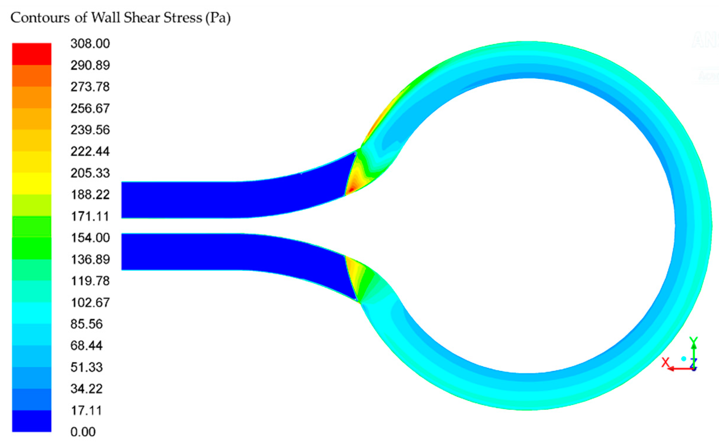
The wall shear stress (WSS) in the rotor is within the range of 46–108 Pa, depicted in
Figure 6. There is a small area near the follow separator where the wall shear stress exceeds the defined acceptable value of 150 Pa. The acceptable amount of wall shear stress is achieved in more than 95% of the pump volume [
26]. The residence time in the pump is 0.0194 s, while the residence between two disks is 0.0127 s. The exposure residence time in the area with higher values of the wall shear stress is 5·10
−4 s. According to Hellums shear stress-exposure time [
26], for exposure residence time of 5·10
−4 s, the acceptable value of shear stress is 700 Pa. The calculated maximum shear stress is 308 Pa, and it is smaller than Hellums.
The scalar shear stress (SSS) for the computational domain is depicted in
Figure 7. The SSS in the rotor is within the range between 4.8·10
−5 and 667.85 Pa.
Figure 6 depicts the SSS on the multiple planes between two disks with different offset from the disk (
z = 0 mm (
Figure 7a),
z = 0.05 mm (
Figure 7b),
z = 0.2 mm (
Figure 7c), and
z = 0.5 mm (
Figure 7d)). The first disk surface is at plane
and the second disk surface is at plane
.
The low SSS is in a range of 0–10 Pa, mid SSS 10–100 Pa, and high SSS >100 Pa. The high SSS is in 10% of the volume, mid SSS is in 10% of the volume, and the low SSS is in the remaining 80% of the volume between disks.
Furthermore, the ∆
p-
Q characteristic curve is presented in
Figure 8. The numerically calculated ∆
p-
Q characteristic curve for the k-omega and the k-epsilon turbulence model are depicted in the diagram, together with the theoretical ∆
p-Q characteristic (Equation (21)).
The theoretical and numerical models concur, as shown in
Figure 8. The numerical ∆
p-
Q characteristic curve is calculated considering flow in the computational domain (with flow separator and connection tubes), while the theoretical ∆
p-
Q characteristic curve has considered only disks. This results in the discrepancy between theoretical and numerical ∆
p-
Q characteristic curves.
The ∆
p-
Q characteristic curve obtained with the theoretical model has a slightly flatter slope. The slope is flatter because the original assumption is that 3/4 of the disk is active and 1/4 is inactive in the flow separator (
Figure 1). The final pump design has 9/10 of the disk as active and 1/10 as inactive in the flow separator, as shown in
Figure 5. Therefore, the ∆
p-
Q characteristic curve obtained with the numerical model has a steeper slope (
Figure 8).
The pump hemocompatibility assessment is only possible through clinical studies and comparison with the existing heart pump. The quality of a bladeless heart pump cannot be fully assessed without experimental research. The only thing that is possible, at this stage of research, is to compare parameters from numerical simulation between two heart pumps. A comparison between the bladeless heart pump presented in this study and HeartMate II (Thoratec Corporation) is conducted numerically. The HeartMate II showed acceptable hemocompatibility and overall good quality during many years of implantation [
36,
37,
38].
The pumps are numerically compared at operating point Δp = 65 mmHg and angular velocity ω = 6000 rpm. The HeartMate II flow is Q = 5 L/min while the bladeless heart pump flow is Q = 5.43 L/min. The HeartMate II pump has a WSS in the range of 0 to 1025 Pa and a SSS in the range of 0.0632 to 3302 Pa. The bladeless heart pump has a WSS in the range of 0 to 308 Pa and an SSS in the range of 0 to 667 Pa. The developed bladeless heart pump has no recirculation zones or stagnation zones, which is very beneficial from the hemocompatibility viewpoint. In addition, WSS and SSS parameters of the bladeless pump are lower than the HeartMate II, which positively affects the hemocompatibility performance of the pump.
In further research, more attention will be focused on the recognized limitations in this study. The numerical analysis is derived for operating point (∆p = 65 mmHg and ω = 6000 rpm). Therefore, further analysis on different operating points is advisable.
The results of the present study show that the shear stress and exposure times in bladeless heart pump are relatively low and acceptable; however, due to assumption of ideal flow separator, the effects of the gap between flow separator and disk are not taken into consideration. The pump is considered as five separate computational domains (five spaces between disks). A numerical CFD simulation, covering a complete computation domain with small gaps, is required to explore effects of gaps on shear stress, which can be subject to future studies. Furthermore, a distance between the two rotating disks is relatively small so the effects of a flow in narrow channels should be considered [
32,
39].
Another limitation of this study is that the blood is assumed as an incompressible single-phase Newtonian fluid. Blood is a multiphase non-Newtonian fluid. In further research, more attention will be focused on a more realistic blood model. In the numerical analysis, the inlet speed is constant although there is a pulsation due to a heartbeat. Therefore, the model with the pulsatile inlet velocity profile is advised for future studies. Moreover, the time dependent non-Newtonian model of blood should be considered.
Separation of blood particles and plasma occurs in the boundary layer of the disk, which has a negative impact on the blood. Blood and disks rotate mostly as a rigid body and the amount of relative velocity between the disk and the blood is small Equation (7). The smaller impact on separation is expected. In further research, it is necessary to investigate the effect of the separation and its influence on the hemocompatibility of this pump.
The results of numerical analysis presented in this paper require experimental validation. From a technological viewpoint, the pump is easy to manufacture, allowing for easy prototyping. The experimental study of the bladeless heart pump prototype, in an ‘open-loop’ mock circulatory system, would provide valuable results and enable the validation of the numerical results.
5. Conclusions
In this paper, a bladeless heart pump design is proposed. Both theoretical and numerical analysis is used to determine the bladeless heart pump design parameters. The pump design parameters are calculated using the Navier-Stokes equations. For the pump operating point of ∆p = 65 mmHg, Q = 5.43 L/min, and ω = 6000 rpm, the design parameters are inner radius R1 = 12 mm, outer radius R2 = 15 mm, a distance between disk of h = 1 mm, and the number of disks is n = 6. The power required to rotate the disks is P = 1.324 W.
The application of computational fluid dynamics is used to define the final geometric design. The evolution of the bladeless heart pump has been continued via improvement of the geometrical aspects to eliminate the recirculation of the blood flow in the inflow and outflow pipes. The turbulence flow regime is modeled with the k-epsilon and k-omega SST turbulence model. The finite volume method has been utilized. The incompressible Newtonian approximation for blood was employed with a fluid density of 1050 kg/m3 and a viscosity of 0.0035 kg/(m·s). It has been shown that the pump does not have recirculation and stagnation zones, which is important from the viewpoint of hemocompatibility.
Wall shear stress, scalar shear stress, and residence (exposure) time are calculated and used to predict pump hemocompatibility. Stagnation and recirculation zones are monitored accordingly. The shear stress in the rotor is in the range 46–108 Pa and the pump residence time is 0.0194 s. The acceptable amount of wall shear stress is achieved in more than 95% of the pump volume. The exposure residence time in the area with higher values of the wall shear stress is 5·10−4 s. According to Hellums shear stress-exposure time, the acceptable value of shear stress is 700 Pa for exposure residence time of 5·10−4 s. The calculated maximum shear stress is 308 Pa, and it is smaller than Hellums. The scalar shear stress SSS in the rotor is within the range between 4.8·10−5 and 667.85 Pa. The high SSS (>100 Pa) is in the 10% of the volume, mid SSS (10–100 Pa) is in the 10% of the volume, and the low SSS (0–10 Pa) is in the remaining 80% of the volume between disks.
Moreover, the ∆p-Q characteristic curve of the bladeless heart pump design is presented. The operating pump conditions can be changed by varying the rotation speed or by adding one or more disks. Due to the positive properties enumerated, the idea of a bladeless pump deserves further development, both numerically and experimentally.


