Abstract
Reliable bond of steel fiber in concrete is a key problem relating to the reinforcing effect of steel fiber on concrete matrix and for the guide in significance for the optimal design of the geometry and mechanical properties of steel fiber. In this paper, on the basis of multi-indices of evaluation for the bond properties of single hooked-end steel fiber, the indices for the evaluation of synergistic bond properties of different deformed steel fibers are proposed. The pull-out tests were carried out for different deformed steel fibers embedded in mortar wet-sieved from self-compacting SFRC with manufactured sand. Fourteen types of steel fibers were used, including six hooked-end, two crimped, four indentation, one milling, and one large-end. The bond strength, bond energy, and bond toughness of single and per unit weight steel fiber were evaluated with the correspondence to the loading status of cracking resistance, normal serviceability, and ultimate bearing capacity of concrete. Results show that the deformed steel fibers presented different bond behaviors, hooked-end, and crimped steel fibers with circular cross-sections and a tensile strength of higher than 1150 MPa have excellent effects of strengthening, energy dissipation, and toughening capacity on self-compacting concrete with a cubic compressive strength of 60 MPa at normal serviceability and ultimate bearing capacity. Indentation, milling, and large-end steel fibers are more suitable for reinforcing the concrete strength due to the rigid bond before concrete cracking. The synergistic working of steel fibers with concrete matrix should be concerned to realize the effects of only or simultaneously reinforcing the strength and toughness of concrete.
1. Introduction
Steel fiber reinforced concrete (SFRC) is a concrete admixing short and random distributed steel fibers [1,2,3]. The main features of SFRC concentrate on the promotion of the tensile performance of conventional concrete by strengthening the tensile properties and related performances with the addition of a certain amount of steel fibers [4,5,6,7]. The structural application of SFRC can improve the mechanical properties and durability of reinforced and prestressed concrete structures [8,9]. To realize the above purposes, the bond performance of steel fiber in concrete matrix is a key point that should ensure its synergistic workings [2,7,10,11].
After decades of research, the mechanism of steel fiber reinforcing concrete becomes clearly understood. Similar to the deformed steel bars in concrete, the bond between deformed steel fiber and a cementitious matrix comes from the chemical adhesion, the physical friction, and the mechanical anchorage [6,7,10]. The chemical adhesion is mainly determined by the properties of the interfacial transition zone between steel fiber and matrix, which plays a role in the initial pull-out process of deformed fiber in matrix. The physical friction is mainly dependent on the surface characteristic of steel fiber. The mechanical anchorage is mainly provided by the geometric deformation of steel fiber and the matrix with rational tensile property, which acts accompanied with the physical friction and plays a major role if the slip of steel fiber takes place [11,12]. Therefore, the deformed geometry of steel fiber has a decisive effect on the bond behavior. This provides plenty of space for the design of steel fiber geometry. Accompanied with different manufacturing techniques, many kinds of steel fibers are supplied in the market.
Theoretically, rational bond performance comes from the properties of steel fiber and concrete themselves, and it matches through their interface. As complex geometry and the rough surface of steel fiber provide higher bond strength, a high tensile strength of steel fiber is needed to avoid breakage during the pulling out of concrete. However, high-strength steel fiber tends to pull out more from a low-strength matrix and presents a smaller anchoring effect compared to low-strength steel fiber [13,14]. These results show insufficient work of high-strength steel fiber. In high-strength concrete, low-strength steel fiber is more prone to break compared to high-strength steel fiber at the same length, which contributes a to the pull-out work and bond toughness [15]. Thus, to determine the reinforcement effects on concrete strength and toughness, the bond behaviors of steel fiber is essential to the rational application of deformed steel fibers. Meanwhile, this is also important to upgrade the mix proportion design of SFRC with high-performance coming from the matching up of steel fibers with concrete [1,2,3,4,16,17,18].
The bond properties of some deformed steel fibers in a cement-based matrix have been experimentally studied [19,20,21]. The bond of straight steel fiber relies on the material characteristics and has no relation to fiber diameter [22,23]. Hooked-end steel fiber presents more flexible characteristics and higher fracture toughness in the pull-out process, and it fails due to the end hook being straightened without fiber breakage [24,25,26]. The peak pull-out load increases with the strength and diameter of hooked-end steel fiber in a concrete matrix with a constant strength [13,24]. The peak pull-out load of hooked-end steel fiber with a tensile strength of 2600 MPa embedded in concretes with a cubic compressive strength of 84 MPa and 44 MPa are nearly two times those of hooked-end steel fiber with a tensile strength of 1250 MPa, respectively [24]. In addition, excellent bond properties and pull-out behaviors were observed in 4D-type and 5D-type hooked-end steel fibers [27,28]. Crimped steel fiber always has a large peak pull-out load, and it tends to increase the tensile strength of concrete [29]. Due to the surface roughness and end hook, the milling steel fiber has a similar bond strength to crimped steel fiber, but it is markedly higher than hooked-end steel fiber. The indentation steel fiber has good mechanical anchorage which could transfer tensile stress to the matrix during the pull-out process, and in turn the matrix splitting may be caused [30]. The helix steel fiber with a flattened end would pull out in normal strength concrete, of 42~54 MPa; however, it would rupture in super-high-strength concrete than 134 MPa [28]. The twin-twisted steel fiber has a higher peak and residual pull-out load compared to the hooked-end steel fiber, and it can significantly improve the toughness and cracking resistance of concrete [31].
However, even though some comparative studies focused on several types of steel fiber, the bond properties were always evaluated separately and without a suitable method [28,30], except for a study in which the pull-out energy per unit volume of steel fiber was used to compare the pull-out energies of steel fibers with different embedded volumes [30]. This leads to the fact that the manufacture of steel fiber is only based on a basic cognition of SFRC, and no in-depth studies have been done on the mechanism of synergistic working of steel fibers with concrete matrix. Therefore, SFRC can be produced with many kinds of steel fibers. This causes confusion on how to select a suitable steel fiber to reach the expected properties of SFRC.
Inherently, a reliable bond of steel fiber in concrete matrix is the foundation of steel fiber reinforcing concrete. The evaluation of bond properties is the focus of this study, and so is optimizing the morphology and geometry of steel fiber and the economic use of steel fiber. Based on the preliminary study of a multi-index synergistic revaluation of bond behavior of single hooked-end steel fiber [32], an experimental study was carried out on the bond properties of different deformed steel fibers in this paper. Meanwhile, to reflect the reasonable composition, workability, and hardened performance of the mortar in concrete, and to simulate the bond condition of steel fibers in SFRC, the mortar used in this study was wet sieved from fresh self-compacting SFRC. Fourteen trials of pull-out specimens were prepared with different types of deformed steel fibers, including hooked-end, crimped, indentation, milling, and large-end. After that, the synergistic bond properties of per unit weight steel fibers that corresponded to the loading conditions of cracking resistance, normal serviceability, and ultimate bearing capacity of concrete were evaluated. Finally, the adaptability of different deformed steel fibers was proposed with the expectation of reinforcing the strength and toughness of concrete.
2. Materials and Methods
2.1. Steel Fibers
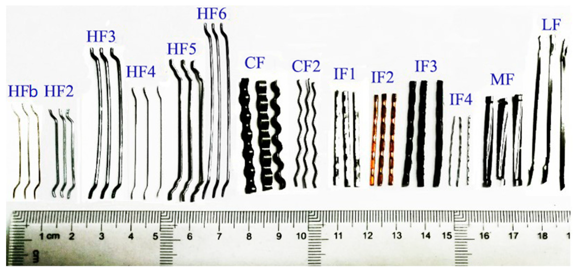
Fourteen types of steel fibers were used, including six hooked-end, two crimped, four indentation, one milling, and one large-end. Their geometry and basic properties are presented in Figure 1 and Table 1. The length lf, the equivalent diameter df, and the tensile strength fsf of steel fiber were tested according to the specification of China code CECS 13 [33].
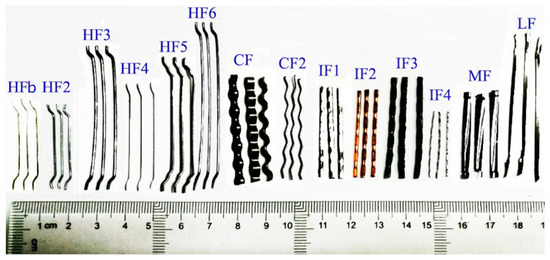
Figure 1.
Different deformed steel fibers.

Table 1.
The characteristic parameters of deformed steel fibers.
2.2. Preparation of Mortar
The mortar was wet sieved from fresh self-compacting SFRC to keep consistent with the bond performance of steel fiber in concrete matrix. All the raw materials of self-compacting SFRC are the same as the previous study [32]. The cement was ordinary silicate cement of grade P.O 42.5 with a density of 3195 kg/m3 and compressive strength of 28 d of 53.8 MPa. The mineral admixture was class-II fly ash with a density of 2349 kg/m3 and an activity index of 80.9%. The crushed limestone was continuous grading with a maximum particle size of 16 mm. The manufactured sand with a fineness modulus of 2.73, an apparent density of 2740 kg/m3 and a stone-powder content of 7.3%. The water reducer was a high-performance polycarboxylic acid type with a water-reducing rate of 30% and a solid content of 35%. The mix water was tap-water.
Self-compacting SFRC was prepared by using the mix proportion design method based on the steel fiber-aggregate skeleton packing test [18,34,35]. The steel fiber, marked as HFb in reference [32], was used with a volume fraction of 1.2%. The detailed mix proportion, the workability, and the basic mechanical properties of self-compacting SFRC and wet-sieved mortar are presented in Table 2. The cube compressive strength fcu and splitting tensile strength fst of self-compacting SFRC were tested according to the specification of China code GB/T50081 [36]. The compressive strength fcm and flexural strength ffm of wet-sieved mortar were tested according to the specification of China code GB/T17671 [37]. Both self-compacting SFRC and wet-sieved mortar had excellent fresh workability.
Table 2.
The mix proportion and properties of self-compacting SFRC and wet-sieved mortar.
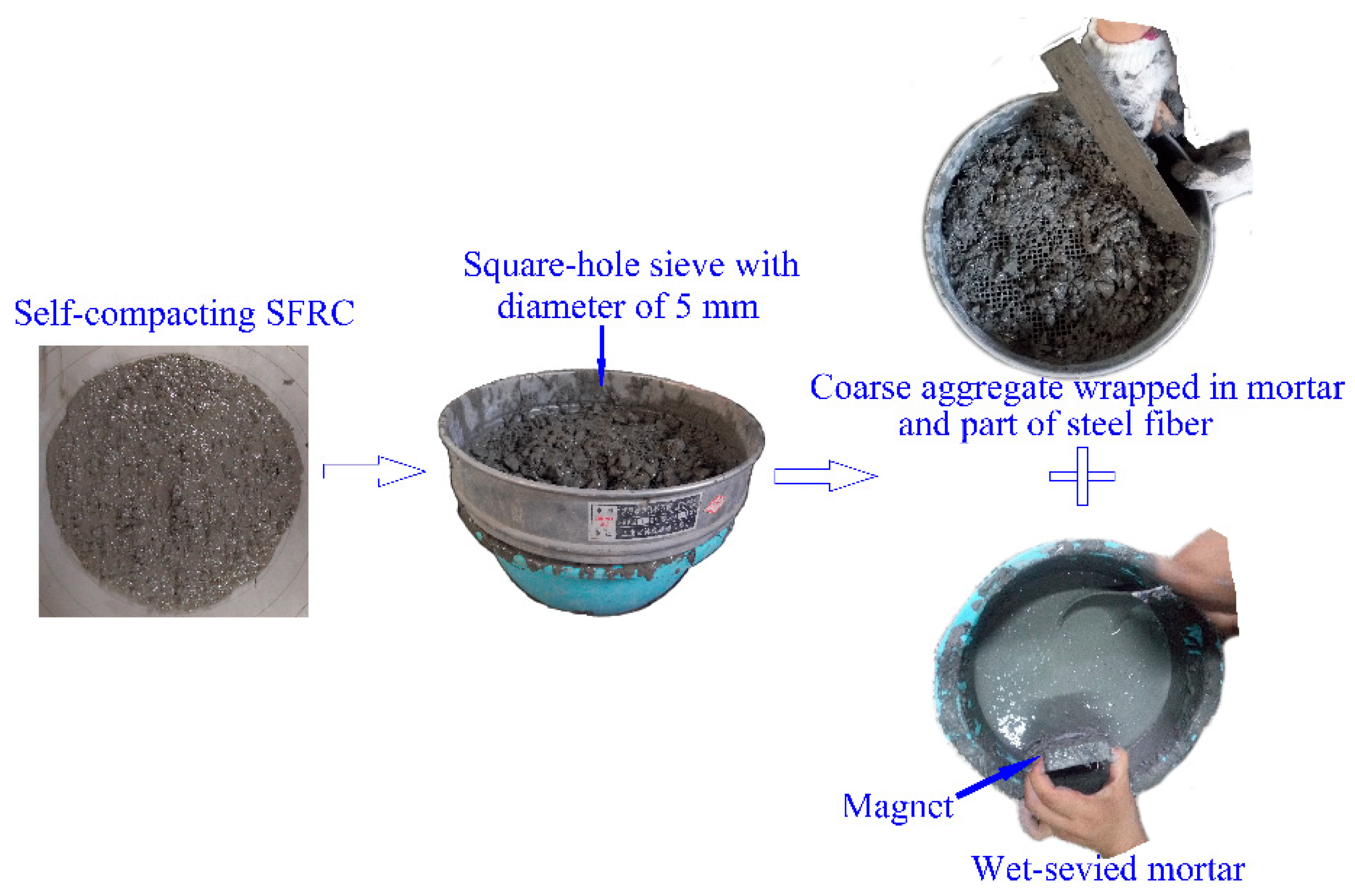
The mixing procedure of self-compacting SFRC was the same as the previous study [18]. Figure 2 presents the detailed wet-sieved process of mortar. First, a certain amount of fresh self-compacting SFRC was put in a sieve with a square hole of 5 mm diameter. Then, the fresh mortar with steel fibers were sieved out. After the steel fibers were sucked out using the magnet, the wet-sieved mortar was obtained.
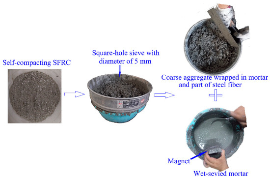
Figure 2.
Detailed wet-sieved process.
The slump flow and flow time T500 were tested on the remaining fresh self-compacting SFRC. The compressive and splitting tensile strengths of self-compacting SFRC were measured with the cubic specimens in the dimension of 150 mm. The micro-slump flow test was carried out for the wet-sieved mortar. The mechanical properties of mortar were tested with prism specimens of 40 mm × 40 mm × 160 mm, and, simultaneously, the tests photos are shown in Figure 3. Results are presented in Table 2.
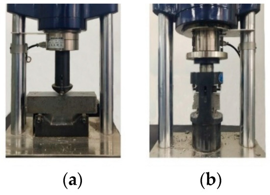
Figure 3.
Tests for mortar: (a) flexural strength; (b) compressive strength.
2.3. Experimental Design for Pull-Out Test
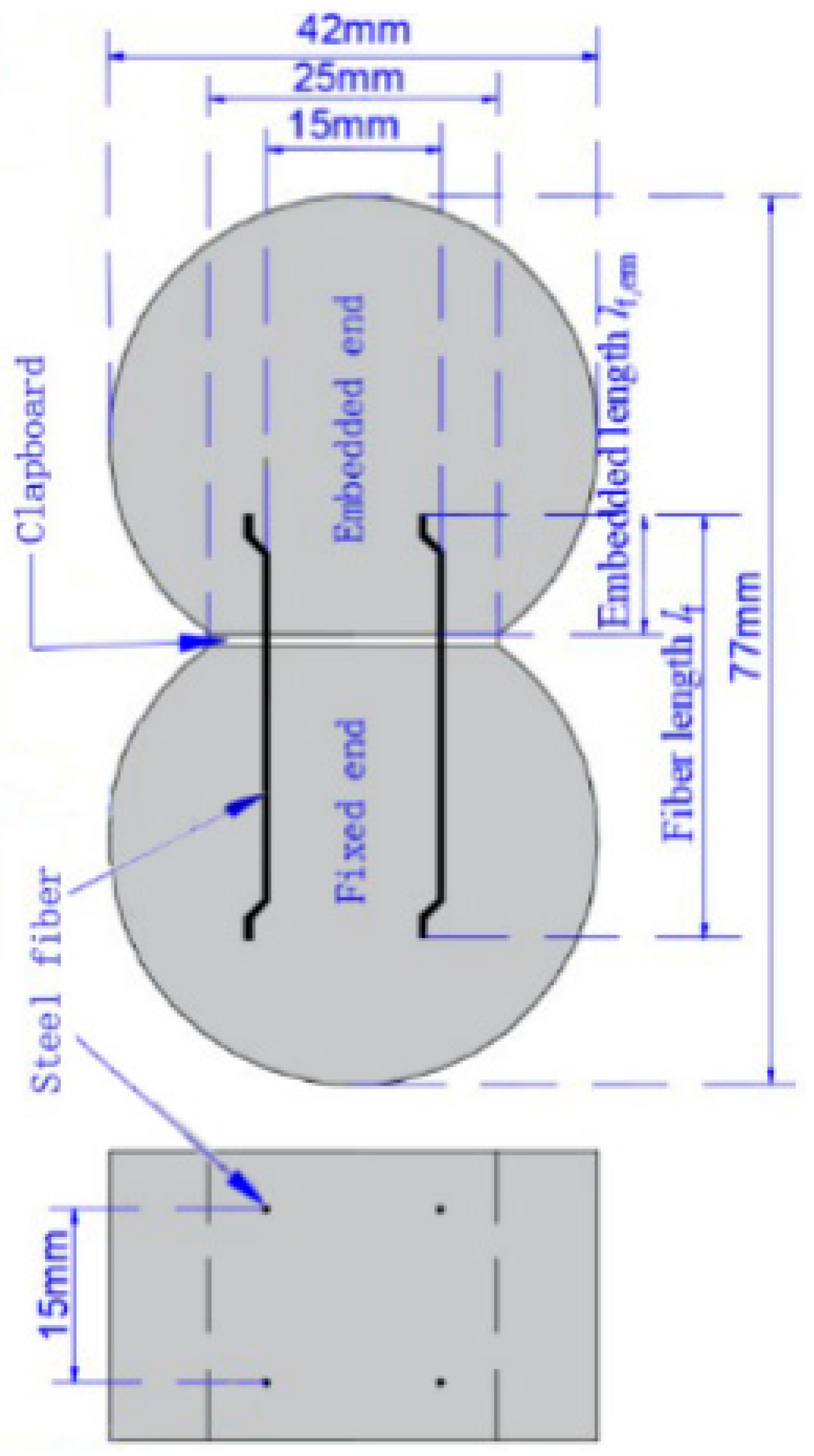
The bond of steel fiber in mortar was measured by the pull-out tests using the figure-eight specimens. Fourteen trials of pull-out tests were designed, each trail has four specimens. For each specimen, four steel fibers were embedded in two-sided mortar specimens. One side is for the fiber with embedded length, and the other side is for the fiber with anchored length. The detailed geometry design of specimens is presented in Figure 4. The embedded length lf.em and anchored length lf.f of steel fibers are given in Table 3. According to the specification of China code CECS 13 [33], the embedded length of each fiber is less than 0.4 times of its length. All the tests were carried out in a lab with a temperature of (20 ± 5) °C. The specimens were cured for 24 h in a standard curing box with a temperature of 20 °C and a humidity of 99%. After that, they were demolded and cured in the standard curing box for 28 d before testing.
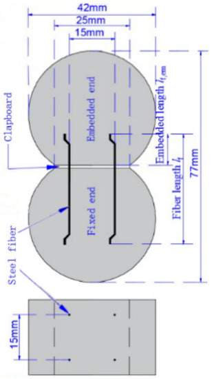
Figure 4.
Detailed specimen design.
Table 3.
The embedded length and anchored length of steel fibers in specimens.
According to the specification of China code CECS13 [33], the specimen was stretched under a loading speed of 0.3 mm/min on an electronic universal testing machine with the load capacity of 10 kN. The load was measured by a loading transducer with a range of 5 kN (produced by Huadong Electronics Co., Ltd., Yantai, China). The relative displacement between fibers and mortar was obtained by the average displacements of two LVDTs with a range of 20 mm (produced by Huayan Electronics Co., Ltd., Wuhan, China). The data were recorded by the Donghua DH3821 static stress-strain testing and analytic system with the frequency of 2 Hz. The testing devices are presented in Figure 5.
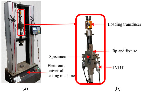
Figure 5.
Detailed test devices: (a) testing machine; (b) pull-out test devices.
2.4. Test Data Processing Method for Pull-Out Test
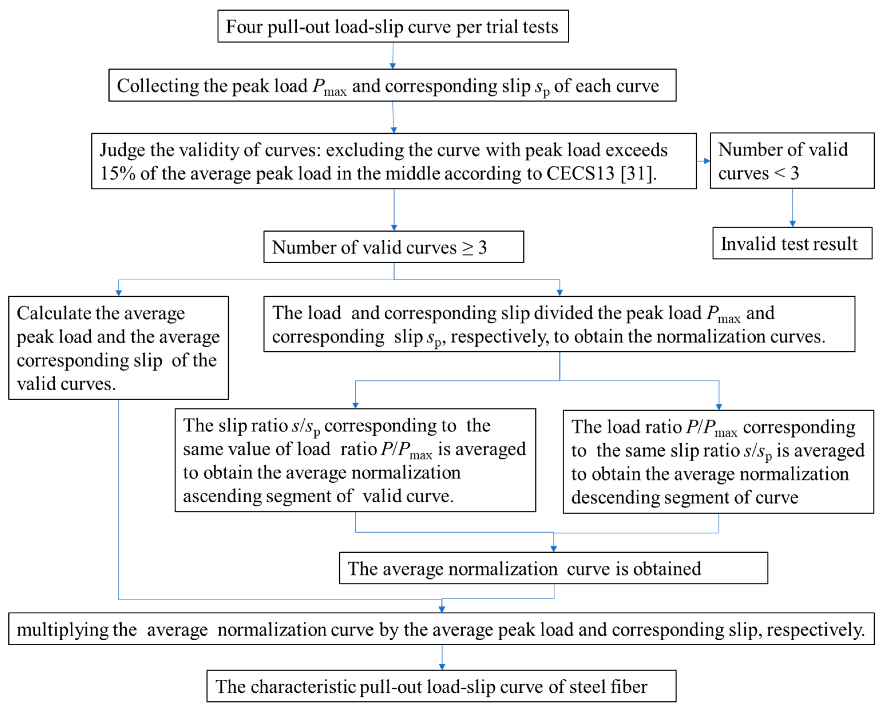
According to the experiment design, one characteristic pull-out load-slip curve of steel fiber was got from the four tested pull-out load-slip curves. The test data is processed according to the specification of China code CECS 13 [33], the procedure is presented in Figure 6.
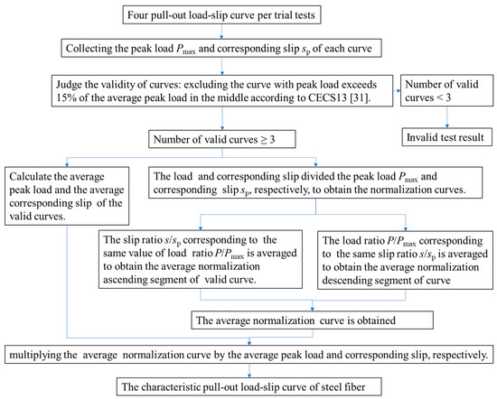
Figure 6.
The procedure of determining the characteristic pull-out load-slip curve.
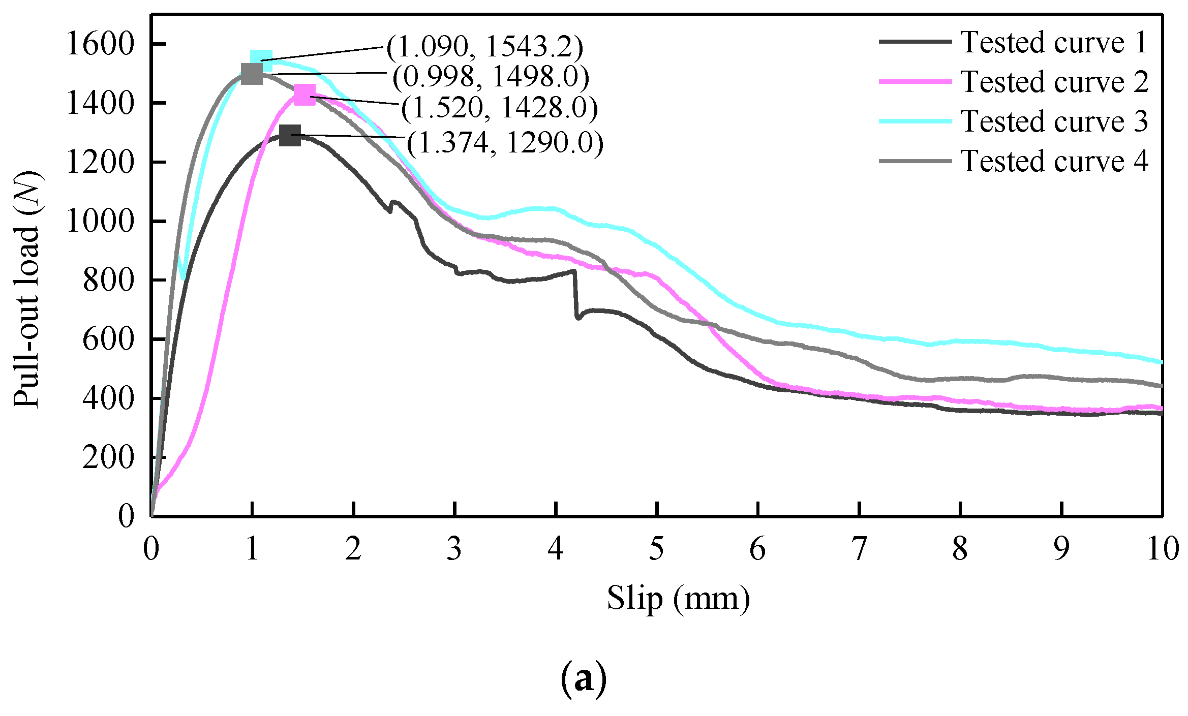
Take the pull-out test of HF6 as example. Four test curves are presented in Figure 7a with their peak loads and corresponding slips. As the load difference was within 15% of the average, all four test curves are valid. The average peak load is 1439.8 N with a corresponding slip of 1.246 mm. As presented in Figure 7b, the normalized curve of each curve is obtained with load and corresponding slip divided by the peak load Pmax and corresponding slip sp, respectively. The slip ratio s/sp, corresponding to the same value of load ratio P/Pmax, is averaged to obtain the average normalized ascending segment of the valid curve. The load ratio P/Pmax, corresponding to the same slip ratio s/sp, is averaged to obtain the average normalized descending segment of the curve. Then, the average normalization curve is obtained. At last, as shown in Figure 7c, the characteristic pull-out load-slip curve of HF6 is obtained by multiplying the average normalized curve with the average of the peak load and corresponding slip, respectively.
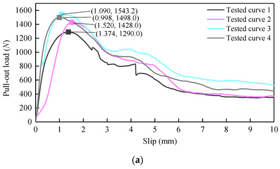
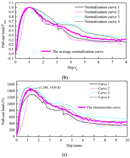
Figure 7.
An example of determining the characteristic pull-out load-slip curve: (a) four test curves; (b) the normalized curves; (c) the characteristic pull-out load-slip curve.
3. Multi-Index Synthetical Evaluation Method of Bond Properties
3.1. Evaluation for Bond Property of Single Steel Fiber
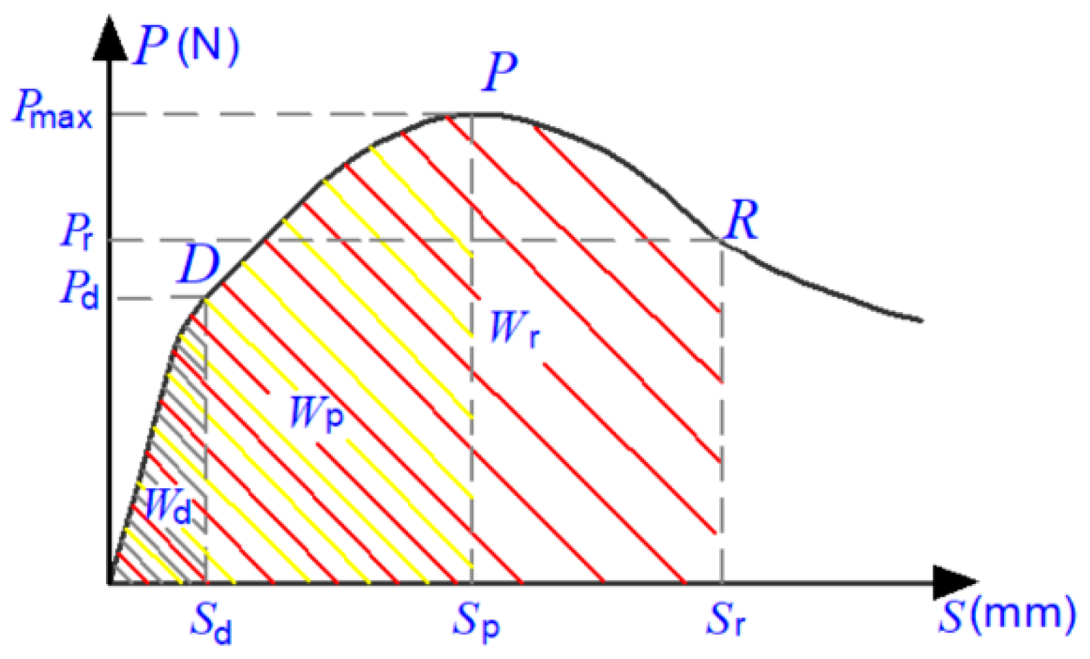
Based on the previous study [32], three key points (marked as points D, P, and R) are noted at the characteristic pull-out load-slip curve of Figure 8, with the characters of slope changing in the ascending portion, at the peak, and in the descending portion. The chemical adhesion is lost at point D, with the debonding pull-out load Pd and corresponding slip sd. The mechanical anchorages accompanied the physical friction along the steel fiber at the D-P-R part, and they obtained the maximum bond strength at the peak point P, with the peak pull-out load Pmax and corresponding slip sp. The mechanical anchorage is lost at point R, with the residual pull-out load Pr and corresponding slip sr.
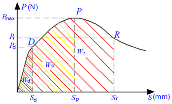
Figure 8.
Typical diagram of characteristic pull-out load-slip curve [32].
The bond strength τmax and strength use efficiency usf, the debonding strength τd and strength ratio ude, the residual bond strength τres and strength ratio ures, the debonding work Wd, the slipping work Wp and the pull-out work Wr, the debonding energy ratio Rd, the slipping energy ratio Rdp, and the pull-out energy ratio Rpr of single steel fiber are calculated as follow:
3.2. Evaluation for Synergistic Bond Property of Unit Weight Steel Fibers
The reinforcement of steel fiber on concrete is dependent on the type, volume fraction, and distribution of fibers [1,2,3,4]. The bond properties of a single fiber could not reflect the synergistic action of steel fibers in concrete. Thus, the unit weight of steel fibers is supposed as a unit of measurement to comprehensively express the synergistic bond properties in this paper.
The mechanical anchoring of hooked-end steel fiber is mainly on the end hook, and embedded length has little influence on its bond properties [32]. Therefore, the synergistic bond strength indices of per unit weight steel fiber, including the debonding load Ld, the bonding load Lm, and the residual bond load Lr, are proposed for hooked-end steel fibers. Their calculation equations are listed as follows:
The mechanical anchoring of the crimped steel fiber, indentation steel fiber, milling steel fiber, and large-end steel fiber are almost linear with the embedded length. Therefore, the synergistic bond strength indices of per unit weight steel fibers, including the debonding load on per embedded length Ldl, the bonding load on per embedded length Lml, and the residual bond load per embedded length Lrl, are proposed with the equations as follows:
The synergistic expended energy indices of per unit weight steel fibers, including the debonding work UWd, the slipping work UWp, and the pull-out work UWr, are proposed for all types of steel fiber in this study as follows:
The equations of synergistic toughness indices of per unit weight steel fibers are the same as those of a single fiber. The debonding energy ratio Rd, slipping energy ratio Rdp, and pull-out energy ratio Rpr are also suitable to evaluate the synergistic energy dissipation capacity of per unit weight steel fiber.
4. Test Results and Analyses
4.1. Failure Modes
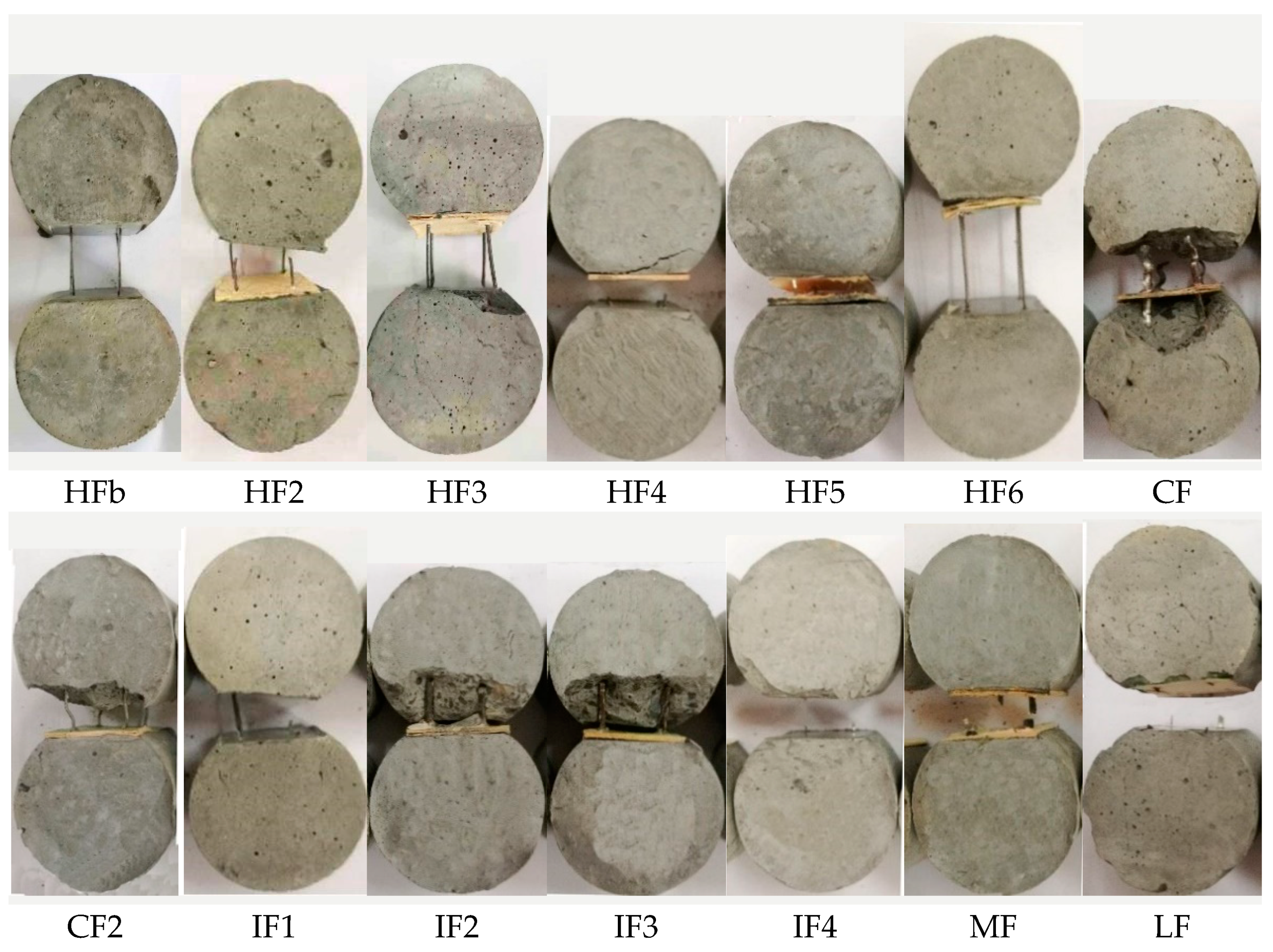
The failure modes of the pull-out tests are listed in Table 4. The typical failure specimens are displayed in Figure 9. Three failure modes of fiber pull-out, mortar cracking, and fiber breakage were observed in this experiment. Fibers would pull out from mortar when the relationships of fiber strength, mortar strength, bond properties, and embedded length are compatible. Fibers would break when the specimen had a relatively long embedded length and strong bond strength or a relatively weak fiber strength. In contrast, mortar cracking occurs when the transversal tensile stress of mortar was induced by the wedged effect of crimped and indentation fiber.
Table 4.
Failure modes of different deformed steel fiber.
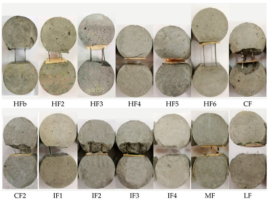
Figure 9.
Typical failure modes of pull-out tests with different steel fibers.
The hooked-end steel fiber HFb, HF2, HF3, and HF6 were pulled out of the mortar. HF4 was broken due to the weak fiber strength of 600 MPa. Due to the mismatch between the strength of 1150 MPa and the strong mechanical anchorage of double hooked-end, HF5 was also broken in the test.
The failure of mortar cracking took place on specimens with crimped steel fibers CF and CF2 and indentation fibers IF2 and IF3. With the pull-out loading increasing, the mortar would crack once the transverse tension component reached the tensile strength of mortar. IF4 broke due to the mismatch between strong mechanical anchorage of indentation and long embedded length. IF1, MF, and LF broke due to their low fiber strengths of 550 MPa, 850 MPa, and 350 MPa.
4.2. Pull-Out Load-Slip Curves
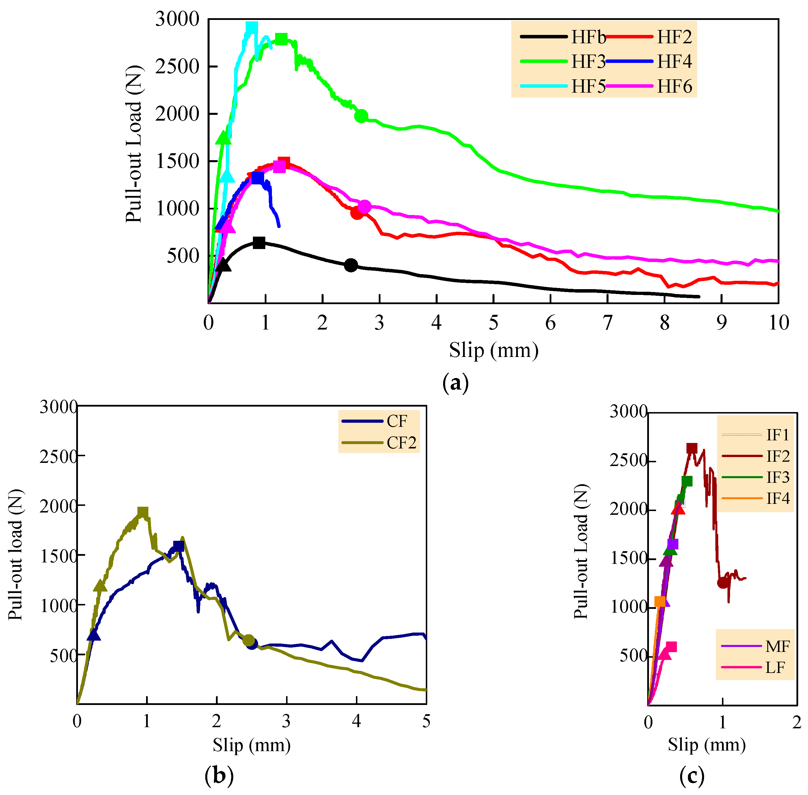
Figure 10 and Table 5 present the characteristic pull-out load-slip curves and their key points of different deformed steel fibers. Steel fibers with the failure modes of fiber breakage would not obtain the characteristic point R.

Figure 10.
The characteristic pull-out load-slip curves of different deformed steel fibers: (a) hooked steel fiber; (b) crimped steel fiber; (c) steel fibers of indentation, milled, and large-end.
Table 5.
Key points of pull-out load-slip curves.
The slip sd ranged from 0.252 mm to 0.335 mm for hooked-end steel fibers, 0.156 mm to 0.404 mm for indentation steel fibers, 0.241 mm and 0.333 mm, respectively, for CF and CF2, and the same as 0.220 mm for LF and MF. No obvious differences were regularly observed in the sd.
The slip sp ranged from 0.760 mm to 1.322 mm for hooked-end steel fibers, 0.156 mm to 0.590 mm for indentation steel fibers, 1.457 mm and 0.944 mm, respectively, for CF and CF2, and 0.314 mm and 0.334 mm, respectively, for LF and MF. The slip sr ranged from 2.50 mm to 2.74 mm for hooked-end steel fibers, 2.50 mm and 2.46 mm, respectively, for CF and CF2, and 1.01 mm for indentation steel fiber IF2.
It could be observed that the hooked-end and crimped steel fibers obviously have larger sp and sr than indentation, milling, and large-end steel fibers. This is due to their different bonding mechanisms. The hooked-end and crimped steel fibers are flexible in the process of the pull-out test, and they have obvious changes in shape. The bond performance of hooked-end steel fiber mainly depends on the mechanical anchoring of shape deformation at the hooked end. The bond performance of crimped steel fiber is mainly decided by the mechanical anchoring of shape deformation of the crimps. Their energy dissipations are dependent on the shape deformations of the fiber with a small damage of mortar.
The indentation, milling, and large-end steel fibers are rigid with less changes in shapes and lengths in the test. Their bond performances are mainly dependent on the mechanical anchoring of fiber surfaces. Their energy dissipations largely depend on the failures of mortar near the interface. These lead to small sp with large damages of mortar observed in the tests.
4.3. Bond Properties of Single Steel Fiber
4.3.1. Bond Strength
Figure 11 presents the bond strength τd, τmax, and τres of steel fibers. The hooked-end steel fiber HF3 has the maximum τd, τmax, and τres. HF2, HF4, and HF5 have a similar τd of about 53~55% of HF3, and their τmax are 61%, 53%, and 70% of HF3, successively. HF2 has the τres of 55% of HF3. HF4 and HF5 have no τres due to their broken fibers. HFb has the smaller τd, τmax, and τres of about 39%, 39%, and 36% of HF3, successively. HF6 has the smallest τd, τmax, and τres of 22%, 24%, and 22% of HF3, successively.
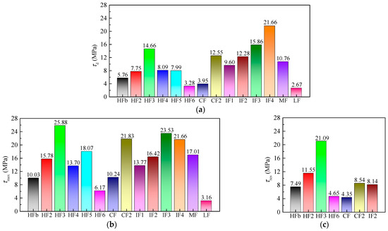
Figure 11.
The bond strengths of characteristic points of different deformed steel fibers: (a) τd; (b) τmax; (c) τres.
The crimped steel fiber CF2 has the maximum τd, τmax, and τres. CF has the τd, τmax, and τres about 31%, 47%, and 51% of CF2, successively. The indentation steel fiber IF3 has the maximum τmax. Next is IF4 and IF2. IF1 has the smallest τd and τmax of about 61% and 59% of IF3. IF4 has the same τd and τmax due to no slope changing observed in the ascending portion of the pull-out load-slip curves of IF4. Compared with other types of steel fibers, the milling steel fiber MF has a good τd and τmax, and the large-end steel fiber LF has the smallest τd and τmax. These differences are also caused by their different mechanical anchoring mechanisms.
Figure 12 presents the strength use efficiency usf of different deformed steel fibers. Considering the safety coefficient of 1.40 for the tensile strength of steel fiber higher than 1100 MPa as that of a high-strength steel bar [38], the usf of 71.4% would keep sufficient reliability to avoid the fracture of steel fiber. At the same time, ensuring the full use of fiber strength, HFb, CF2, and IF3 are suitable in the mortar of this test.
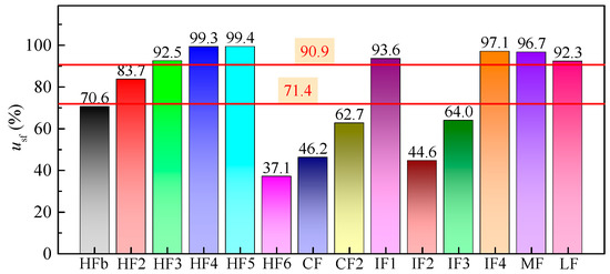
Figure 12.
The strength uses efficiency usf of different deformed steel fibers.
The usf of HF6 is only 37%. This indicates that the fiber strength has not fully played due to the weak mechanical anchoring in the mortar. Therefore, the hooked-end shape of HF6 does not match its fiber strength. The usf of IF2 is 44.6%, due to the mortar cracking in the test. This indicates that the designed embedded length of IF2 is too long, and IF2 would be suitable for concrete higher than 60 MPa.
Considering the safety coefficient of 1.10 for the tensile strength of steel fiber less than 800 MPa as that of normal-strength steel bar [38], the usf of 90.9% would keep sufficient reliability to avoid the fracture of steel fiber. The usf of HF4, IF1, MF, and LF are higher than 90.9%, which corresponds to the fibers broken in the tests. Only the CF has usf of 46.2% with the cracking of mortar.
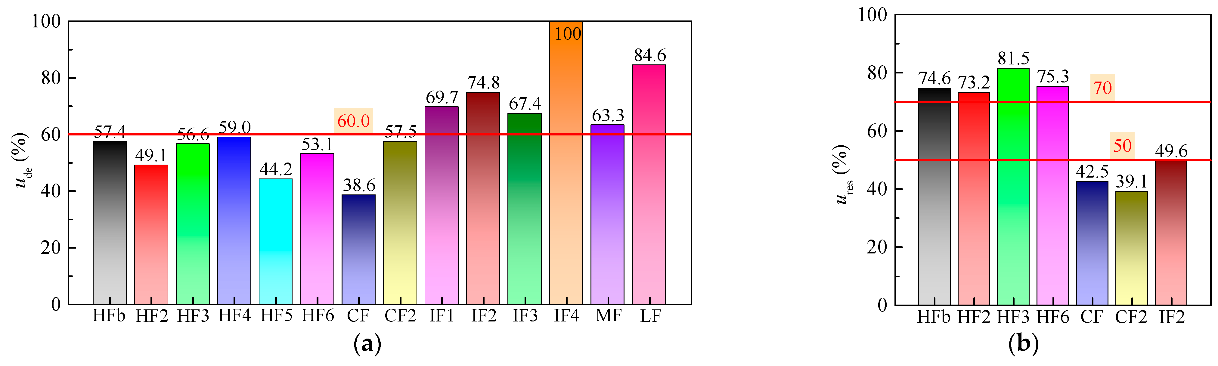
Figure 13 presents the strength ratios ude and ures of different deformed steel fibers. All ude for hooked-end and crimped steel fibers are less than 60%. Those of indentation, milling, and large-end steel fibers are higher than 60%. This indicates that the chemical adhesion accounts for a large proportion in indentation, large-end, and milling steel fibers.

Figure 13.
The strength ratios of different deformed steel fibers: (a) ude; (b) ures.
The ures of hooked-end steel fibers are higher than 70%, while those of CF, CF2, and IF2 are less than 50%. This corresponds to the CF, CF2, and IF2 with failure mode of mortar cracking at point P due to the mechanical anchorages and the physical friction along steel fibers obviously decreasing.
4.3.2. Energy Ratios
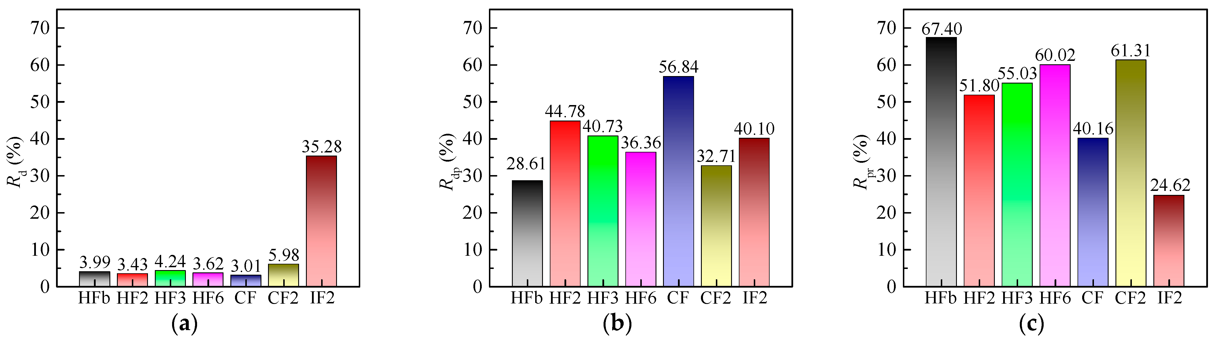
Figure 14 displays the energy ratios of different deformed steel fibers. Hooked-end and crimped steel fibers have a low toughening capacity before the concrete cracking, with the debonding energy ratios Rd no more than 6%, while the indentation steel fiber IF2 has an excellent toughening capacity with an Rd of 35.28%.
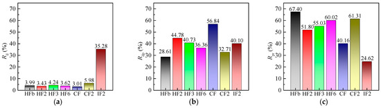
Figure 14.
The energy ratios of different deformed steel fibers: (a) Rd; (b) Rdp; (c) Rpr.
Suitable toughening capacities in the normal serviceability of concrete were observed in hooked-end, crimped, and indentation steel fibers. The slipping energy ratios Rdp of hooked-end steel fibers are 28.61~44.78%, while those of CF, CF2, and IF2 are 56.84%, 32.71% and 40.10%, respectively.
Excellent toughening capacities in the ultimate bearing capacity of concrete were observed in hooked-end steel fibers and crimped steel fiber CF2, with the pull-out energy ratios Rpr higher than 50%. The indentation steel fiber IF2 has a low toughening capacity in the ultimate bearing capacity of concrete with Rpr of 24.62%.
4.4. Synergistic Bond Properties of Per Unit Weight Steel Fiber
4.4.1. Bond Loads of Hooked-End Steel Fiber
Table 6 presents the bond loads of per unit weight hooked-end steel fibers. HF2 has the highest bond loads Lm and Lr. Next are HF3 and HFb. HFb, HF2, and HF3 have similar values of Ld, which are almost 1.59~2.22 times that of HF4, HF5, and HF6. Combined with the analysis of a single fiber, HF4 and HF5 are unsuitable for the self-compacting SFRC in this test, due to the fact that their strengths and shapes are mismatched with the concrete strength. HF6 is also unapplicable due to its low bond strength.
Table 6.
The bond loads of per unit weight hooked-end steel fibers.
4.4.2. Bond Loads on Per Embedded Length of Other Types of Steel Fiber
Table 7 presents the bond loads on per embedded length of per unit weight steel fibers. Compared with CF, CF2 has better bond strength in the whole pull-out process. Ldl, Lml, and Lrl of CF2 are 4.98, 3.37, and 3.07 times that of the CF, successively. IF4 has the best bond strength in the ascending segment of pull-out load-slip curves. Ldl and Lml of IF4 are 3.70 and 2.13 times that of the CF2, respectively.
Table 7.
The bond loads on per embedded length of per unit weight steel fibers.
MF has a suitable bond strength in the ascending segment of pull-out load-slip curves; Ldl and Lml of MF are 91% and 83% of the CF2, respectively, while LF has the worst bond strength. Ldl and Lml of LF are 13% and 9% of the CF2, respectively. This is due to the low fiber strength of LF. Compared with hooked-end steel fibers, IF1, IF2, IF3, IF4, MF, and LF are bond strength enhanced type fibers.
4.4.3. Pull-Out Works of Per Unit Weight Steel Fibers
Table 8 presents the pull-out works of per unit weight steel fibers. HF2 has the best pull-out work UWmax and UWres. It means that HF2 has a good energy dissipation effect, from normal serviceability to ultimate bearing capacity. Next is HF3 and HFb. UWde and UWmax of HF4, HF5, and HF6 are about half of HF2. These also show the inapplicability of HF4, HF5, and HF6 in the self-compacting SFRC of this test.
Table 8.
The pull-out works of per unit weight steel fibers.
Compared with CF, CF2 has better pull-out work in the whole pull-out process. UWde, UWmax, and UWres of CF2 are about 5.94, 1.93, and 2.98 times that of the CF, successively. CF2 has good restriction of cracking developing, the UWde of which is about 1.41 times that of the HF2. The energy dissipation effect of CF2, from normal serviceability to ultimate bearing capacity, is between HFb and HF3. The UWmax and UWres of CF2 are about 65% and 81% of the HF2, due to the reduced wrapping effect of mortar after cracking.
IF4 has the best restriction of cracking developing, the UWde of which is 1.96 times that of the HF2. Nest is IF2, the UWde of which is 1.21 times that of the HF2. However, the indentation steel fibers show a poor energy dissipation from normal serviceability to ultimate bearing capacity; the UWmax of IF1, IF2, IF3, and IF4 are only about 15%, 18%, 7%, and 14% of the HF2.
MF has a suitable restriction of cracking developing, the UWde of which is 0.78% of the HF2. While LF has the worst pull-out work in the ascending segment of pull-out process among all steel fibers, the UWde and UWmax are only 22% and 3% of the HF2, respectively.
5. Conclusions
Based on the studies of this paper, conclusions can be drawn as follows:
- Based on the multi-index synthetical evaluation of pull-out behaviors of hooked-end steel fiber embedded in mortars, the indices for evaluating the synergistic bond properties of different deformed steel fibers are proposed by using the concept of per unit weight of steel fibers. The bond strength indices of the loads of per unit weight steel fibers and the load on per embedded length of per unit weight steel fibers, the expended energy indices of the work of per unit weight steel fibers and the toughness indices of energy ratios are proposed to comprehensively express the bond properties, considering the geometry and numbers of different deformed steel fibers.
- Hooked-end steel fibers with a tensile strength higher than 1150 MPa are strength and toughness enhanced type fibers with different degrees of enhancement. HFb, HF2, and HF3 with tensile strengths between 1150–1500 MPa have excellent strengthening, energy dissipation effect, and toughening capacity in the normal serviceability and ultimate bearing capacity of concrete. Their strength use efficiency usf was close to the limit of 71.4% for high-strength steel bar. However, HF5 with a tensile strength of 1150 MPa could develop a higher strength use efficiency usf that reached about 100%, which led the broken steel fiber due to the strong anchorage of a 4-D type hooked-end. HF6 with a tensile strength of 2200 MPa had a large affluence with a smaller strength use efficiency usf of 37.1%. Although they all match the self-compacting SFRC with cubic compressive strength of 60 MPa, it is better to produce steel fiber with appropriate geometry and tensile strength for the economical application with the premise of reliability. Hooked-end steel fiber HF4 with a tensile strength of 600 MPa was broken during the pull-out process, which can be used mainly for the improvement of the strength of concrete.
- Crimped steel fiber CF2 with a tensile strength of 2000 MPa had excellent bond strength and toughness, which provides the strengthening and energy dissipation effect and the toughening capacity in the cracking resistance, normal serviceability, and ultimate bearing capacity of concrete, due to matching with the self-compacting SFRC with a cubic compressive strength of 60 MPa. The rectangular sectional crimped steel fiber CF with a tensile strength of 800 MPa had a poor bond behavior in this test.
- The indentation, milled, and large-end steel fibers are strength enhanced type fibers with a certain energy dissipation ability and toughening capacity, before the bond strength reached the maximum. The bond relies mainly on the geometry of steel fiber with different tensile strength.
- To realize the expected properties of concrete reinforced by steel fibers, the bond property of steel fiber in mortar can be used for the fiber selection. Not all kinds of steel fiber can simultaneously improve the strength and toughness of concrete. Even if the same kind of steel fiber is used, the reinforcing effect may be different in quantity. Therefore, the in-depth study of bond properties in relation to the mechanical properties of SFRC is necessary to increase the reinforcing and economic efficiency of steel fibers.
Author Contributions
Conceptualization and methodology, X.D. and M.Z.; validation, J.L.; formal analysis, X.D. and M.Z.; investigation, H.G., M.Z. and Z.C.; data curation, X.D. and H.G.; writing—original draft preparation, M.Z., X.D. and Z.C.; writing—review and editing, funding acquisition, X.D. and J.L. All authors have read and agreed to the published version of the manuscript.
Funding
This research was funded by Natural Science Foundation of Henan, China, grant number “212300410192”; Key Scientific and Technological Research Project of University in Henan, China, grant number “20A560015”; Attracting Foreign Talents Fund of Henan, China, grant number “YWZ2018-6-HS2”.
Institutional Review Board Statement
Not applicable.
Informed Consent Statement
Not applicable.
Data Availability Statement
Not applicable.
Conflicts of Interest
The authors declare no conflict of interest.
Nomenclature
| lf | the length of steel fiber, |
| df | The equivalent diameter of steel fiber. |
| lf/df | The aspect ratio of steel fiber. |
| Nsf | The number of steel fiber per kilogram. |
| fsf | The tensile strength of steel fiber. |
| fcu | The cube compressive strength of self-compacting SFRC. |
| fst | The splitting tensile strength of self-compacting SFRC. |
| fcm | The compressive strength of wet-sieved mortar. |
| ffm | The flexural strength of wet-sieved mortar. |
| lf.em | The embedded length of steel fiber in mortar. |
| lf.f | The anchored length of steel fiber in mortar. |
| P | The pull-out load of steel fiber. |
| Pmax | The peak value of pull-out load of steel fiber. |
| Pd | The debonding pull-out load of steel fiber. |
| Pr | The residual pull-out load of steel fiber. |
| s | The bond slip of steel fiber under the P. |
| sp | The peak bond slip of steel fiber under the Pmax. |
| sd | The bond slip corresponded to the Pd. |
| sr | The bond slip corresponded to Pr. |
| τmax | The bond strength of steel fiber. |
| usf | The strength use efficiency of steel fiber. |
| τd | The debonding strength of steel fiber. |
| ude | The strength ratio corresponded to the τd. |
| τres | The residual bond strength of steel fiber. |
| ures | The strength ratio corresponded to the τres. |
| Wd | The debonding work of single steel fiber. |
| Ws | The slipping work of single steel fiber. |
| Wp | The work corresponded to the peak load. |
| Wr | The pull-out work of single steel fiber. |
| Rd | The debonding energy ratio. |
| Rdp | The slipping energy ratio. |
| Rpr | The pull-out energy ratio. |
| Ld | The debonding load of per unit weight hooked-end steel fibers. |
| Lm | The bonding load of per unit weight hooked-end steel fibers. |
| Lr | The residual bond load of per unit weight hooked-end steel fibers. |
| Ldl | The debonding load on per embedded length of per unit weight steel fibers except for hooked-end ones. |
| Lml | The bonding load on per embedded length of per unit weight steel fibers except for hooked-end ones. |
| Lrl | The residual bond load on per embedded length of per unit weight steel fibers except for hooked-end ones. |
| UWd | The debonding work of per unit weight steel fibers. |
| UWp | The slipping work of per unit weight steel fibers. |
| UWr | The pull-out work of per unit weight steel fibers. |
References
- Ministry of Housing and Urban-Rural Development of the People’s Republic of China. Steel Fiber Reinforced Concrete, JG/T 472-2015; China Architecture & Building Press: Beijing, China, 2015. [Google Scholar]
- Zhao, M.L.; Li, J.; Law, D. Effects of flowability on SFRC fibre distribution and properties. Magaz. Concr. Res. 2017, 69, 1043–1054. [Google Scholar] [CrossRef]
- Ding, X.X.; Li, C.Y.; Han, B.; Lu, Y.Z.; Zhao, S.B. Effects of different deformed steel-fibers on preparation and fundamental properties of self-compacting SFRC. Constr. Build. Mater. 2018, 168, 471–481. [Google Scholar] [CrossRef]
- Zhao, M.L.; Zhao, M.S.; Chen, M.H.; Li, J.; David, L. An experimental study on strength and toughness of steel fiber reinforced expanded-shale lightweight concrete. Constr. Build. Mater. 2018, 183, 493–501. [Google Scholar] [CrossRef]
- Ding, X.X.; Li, C.Y.; Zhao, M.L.; Li, J.; Geng, H.B.; Lian, L. Tensile strength of self-compacting steel fiber reinforced concrete evaluated by different test methods. Crystals 2021, 11, 251. [Google Scholar] [CrossRef]
- Li, C.Y.; Shang, P.R.; Li, F.L.; Feng, M.; Zhao, S.B. Shrinkage and mechanical properties of self-compacting SFRC with calcium sulfoaluminate expansive agent. Materials 2020, 13, 588. [Google Scholar] [CrossRef] [Green Version]
- Ding, X.X.; Li, C.Y.; Li, Y.Z.; Song, C.; Zhao, S.B. Experimental and numerical study on stress-strain behavior of self-compacting SFRC under uniaxial compression. Constr. Build. Mater. 2018, 185, 30–38. [Google Scholar] [CrossRef]
- Jerath, S.; Shibani, M.M. Dynamic modulus for reinforced concrete beams. J. Struct. Eng. 1984, 110, 1405–1410. [Google Scholar] [CrossRef]
- Bonopera, M.; Chang, K.C.; Chen, C.C.; Sung, Y.C.; Tullini, N. Prestress force effect on fundamental frequency and deflection shape of PCI beams. Struct. Eng. Mech. 2018, 67, 255–265. [Google Scholar]
- Zhao, M.S.; Zhang, X.Y.; Song, W.H.; Li, C.Y.; Zhao, S.B. Development of steel fiber reinforced expanded- shale lightweight concrete with high freeze-thaw resistance. Adv. Mater. Sci. Eng. 2018, 2018, 9573849. [Google Scholar] [CrossRef] [Green Version]
- Cunha, V.M.C.F.; Barros, J.A.O.; Sena-Cruz, J.M. Pullout behavior of steel fibers in self-compacting concrete. J. Mater. Civil. Eng. 2010, 22, 1–9. [Google Scholar] [CrossRef] [Green Version]
- Abdallah, S.; Fan, M.; Cashell, K.A. Bond-slip behaviour of steel fibres in concrete after exposure to elevated temperatures. Constr. Build. Maters. 2017, 140, 542–551. [Google Scholar] [CrossRef]
- Soetens, T.; Gysel, A.V.; Matthys, S.; Taerwe, L. A semi-analytical model to predict the pull-out behaviour of inclined hooked-end steel fibres. Constr. Build. Mater. 2013, 43, 253–265. [Google Scholar] [CrossRef]
- Isla, F.; Ruano, G.; Luccioni, B. Analysis of steel fibers pull-out. Experimental study. Constr. Build. Mater. 2015, 100, 183–193. [Google Scholar] [CrossRef]
- Oliveira, F.L.D. Design-Oriented Constitutive Model for Steel Fiber Reinforced Concrete. Ph.D. Thesis, Universitat Politècnica De Catalunya, Barcelona, Spain, 2010. [Google Scholar]
- Zhao, S.B.; Du, H.; Qian, X.J.; Li, C.Y. Study on direct mix design method for steel fiber reinforced high-strength concrete. China Civ. Eng. J. 2008, 41, 1–6. [Google Scholar]
- Zhao, S.B.; Li, C.Y.; Du, H.; Qian, X.J. Study of steel fiber reinforced high-strength concrete containing large coarse aggregate. J. Build. Mater. 2010, 13, 155–160. [Google Scholar]
- Ding, X.X.; Zhao, M.L.; Li, J.; Shang, P.R.; Li, C.Y. Mix proportion design of self-compacting SFRC with manufactured sand based on the steel fiber-aggregates skeleton packing test. Materials 2020, 13, 2833. [Google Scholar] [CrossRef]
- Caggiano, A.; Xargay, H.; Folino, P.; Martinelli, E. Experimental and numerical characterization of the bond behavior of steel fibers recovered from waste tires embedded in cementitious matrices. Cement. Concrete. Comp. 2015, 62, 146–155. [Google Scholar] [CrossRef]
- Xu, J.E.; Sun, J.Y.; Luo, G.D. Experimental study on the bond load between steel fiber and concrete based on orthogonal design method. In Proceedings of the Fourth National Conference on Fiber Cement and Fiber Concrete (I), Jiujiang, China, 20–23 July 1992. [Google Scholar]
- Yang, M. Strengthening and Toughening Mechanism of Steel Fiber Reinforced High-Strength Concrete and Design Method Based on Toughness. Ph.D. Thesis, Dalian University of Technology, Dalian, China, 2006. [Google Scholar]
- Sun, W.; Gao, J.M.; Qin, H.G. Studies on bond strength of interface between fiber and matrix in steel fiber reinforced concrete. J. Chin. Ceram. Soc. 1985, 3, 292–300. [Google Scholar]
- Banholzer, B.; Brameshuber, W.; Jung, W. Analytical evaluation of pull-out tests-the inverse problem. Cement. Concrete. Comp. 2006, 28, 564–571. [Google Scholar] [CrossRef]
- Meschke, R.B.G.; Song, F.B.; Zhan, Y.J. Experimental, analytical and numerical analysis of the pullout behaviour of steel fibres considering different fibre types, inclinations and concrete strengths. Struct. Concr. 2014, 15, 126–135. [Google Scholar]
- Esmaeili, J.; Andalibi, K.; Gencel, O.; Maleki, F.K.; Malekid, V.A. Pull-out and bond-slip performance of steel fibers with various ends shapes embedded in polymer-modified concrete. Constr. Build. Mater. 2021, 271, 121531. [Google Scholar] [CrossRef]
- Kim, D.J.; El-Tawil, S.; Naaman, A.E. Effect of matrix strength on pullout behavior of high strength deformed steel fibers. In Symposium—Four Decades of Progress in Prestressed Concrete, Fiber Reinforced Concrete, and Thin Laminate Composites; Montesinos, G.J., Balaguru, P., Eds.; ACI Special Publications: Farmington Hills, MI, USA, 2010; pp. 135–150. [Google Scholar]
- Lu, J.; Lin, L. Upgrading effect of new end-hooked steel fiber on properties of concrete. New Build. Mater. 2014, 2, 19–22. [Google Scholar]
- Abdallah, S.; Rees, D.W.A. Comparisons between pull-out behaviour of various hooked-end fibres in normal–high strength concretes. Int. J. Concr. Struct. Mater. 2019, 13, 27. [Google Scholar] [CrossRef]
- Zhao, L.J.; Li, N. Drawing test of profiled steel fiber in cement mortar matrix. Opencast Min. Technol. 2015, 9, 99–101. [Google Scholar]
- Feng, H.; Sheikh, M.N.; Hadi, M.N.S.; Feng, L.; Gao, D.Y.; Zhao, J. Pullout behaviour of different types of steel fibres embedded in magnesium phosphate cementitious matrix. Int. J. Concr. Struct. Mater. 2019, 13, 33. [Google Scholar] [CrossRef]
- Lee, J.H.; Kighuta, K. Twin-twist effect of fibers on the pullout resistance in cementitious materials. Constr. Build. Mater. 2017, 146, 555–562. [Google Scholar] [CrossRef]
- Ding, X.X.; Zhao, M.L.; Li, C.Y.; Li, J.; Zhao, X.S. A multi-index synthetical evaluation of pull-out behaviors of hooked-end steel fiber embedded in mortars. Constr. Build. Mater. 2021, 276, 122219. [Google Scholar] [CrossRef]
- China Association for Engineering Construction Standardization. Standard Test Methods for Fiber Reinforced Concrete, CECS13: 2009; China Planning Press: Beijing, China, 2009. [Google Scholar]
- Zhao, M.L.; Ding, X.X.; Li, J.; Law, D. Numerical analysis of mix proportion of self-compacting concrete compared to ordinary concrete. Key Eng. Mater. 2018, 789, 69–75. [Google Scholar] [CrossRef]
- Ding, X.X.; Zhao, M.L.; Zhou, S.Y.; Fu, Y.; Li, C.Y. Statistical analysis and preliminary study on the mix proportion design of self-compacting steel fiber reinforced concrete. Materials 2019, 12, 637. [Google Scholar] [CrossRef] [Green Version]
- Ministry of Housing and Urban-Rural Development of the People’s Republic of China. Standard for Test Methods of Concrete Physical and Mechanical Properties, GB/T 50081-2019; China Building Industry Press: Beijing, China, 2019. [Google Scholar]
- The State Bureau of Quality and Tehnical Supervision. Method of Testing Cements-Determination of Strength, GB/T 17671-1999; Standards Press of China: Beijing, China, 1999. [Google Scholar]
- Ministry of Housing and Urban-Rural Development of the People’s Republic of China. Design Code for Concrete Structures, GB/T 50010-2010; China Building Industry Press: Beijing, China, 2015. [Google Scholar]


Publisher’s Note: MDPI stays neutral with regard to jurisdictional claims in published maps and institutional affiliations. |
© 2021 by the authors. Licensee MDPI, Basel, Switzerland. This article is an open access article distributed under the terms and conditions of the Creative Commons Attribution (CC BY) license (https://creativecommons.org/licenses/by/4.0/).