Abstract
This paper analyses the construction time and advance rate of a 3 km long drill and blast tunnel under various geological conditions using an upgraded NTNU drill and blast prediction model. The analysis was carried out for the five types of Korean tunnel supports according to the rock mass quality (from Type 1, meaning a very good rock mass quality; to Type 5, meaning a very poor rock mass quality). Four kinds of rock properties, as well as the rock mass quality, for each tunnel support type were applied to simulate different geological conditions based on previous studies and the NTNU model. The construction time was classified into five categories: basic, standard, gross, tunnel and total, according to the operation characteristics to more effectively analyse the time. In addition, to consider the actual geological conditions in tunnelling, the construction times for the three mixed geological cases were analysed. It was found that total construction time of a tunnel covering all the operations and site preparations with a very poor rock mass quality was more than twice that of a tunnel with a very good rock mass quality for the same tunnel length. It is thought that this study can be a useful approach to estimating the construction time and advance rate in the planning or design stage of a drill and blast tunnel.
1. Introduction
In tunnel construction, it is typical to compare the advantages and disadvantages of two major methods, drill and blast (D&B), and TBM, in the planning or design stage. Essentially, a tunnel excavation method is chosen as a result of interaction among various elements such as safety, cost and time schedule [1]. The construction time is an important factor in the selection of the construction scheme (number of construction lots and intermediate construction access) and the construction method (excavation method, lining system) [2].
Hence, for a TBM tunnel, many studies focused on estimating advance rates [3,4,5,6,7,8,9], and thus CSM model [10], NTNU model [11], QTBM [12], etc., were established.
Meanwhile, the D&B method is a very flexible and adaptable process with respect to the excavation of intermediate cross sections or cross sections of any shapes and sizes, and it has advantages in installing the various types of primary rock supports such as shotcrete, wire-mesh, rock-bolt and forepoling. Furthermore, D&B has a short time-mobilisation, as standard equipment is used during the excavation, and has a lower advance rate (performance rate) in most cases, compared to the TBM technology [13].
For a D&B tunnel, some researchers also studied and suggested the usual advance rate of a D&B tunnel. Daller (2017) found that in tunnelling by the New Austrian Tunnelling Method (NATM), the average daily advance rates could reach 10 to 15 m in favourable rock conditions with peak rates up to 20 m/day. Even in poor conditions (e.g., in fault zones), rates of 2 to 3 m/day are possible due to the high flexibility of the method. In crushed zones, it can be easier than TBM to advance due to the high versatility of the method [3], and the advance rate of D&B in a good rock mass is usually 6 m/day [14] or generally 3–9 m/day [15] Hence, when analysing or mentioning advance rates, geological conditions always need to be taken into account.
In addition, some previous studies estimated the construction time or advance rate for the D&B method. Einstein et al. [16,17] suggested Decision Aids for Tunnelling (DAT), a computer-based simulation tool used to determine tunnel construction cost and time through a probabilistic approach. Špačková et al. [18] also suggested a probabilistic model considering the uncertainties in geotechnical conditions, excavation performance, and the risk of extraordinary events based on the Dynamic Bayesian Network technique to estimate tunnel construction time. Nataadiningrat et al. [19] simulated the operations of NATM (New Austrian Tunnelling Method) to analyse the productivity and sensitivity of the method using CYCLONE softwares. Periku and Aga [20] defined the time needed for any particular process using the drill and blast tunnel excavation method with 737 field measurements, concluding that the best construction performance is reached when distance from tunnel adit and tunnel face is smaller than 200 meters.
Kim et al. [21] estimated the tunnel construction time for three tunnels by using the Korean Standard of Construction Estimate, which is usually applied to tunnel design in Korea and was established on a deterministic basis, and the results showed differences of between 7% and 50% from the actual operation times.
Meanwhile, in Norway, the model for prediction of advance rate as well as excavation cost of D&B tunnels has been developed since 1975 [22,23,24], which is called a NTNU D&B prediction model. This is an empirical prediction model established on the basis of a substantial amount of field data from various subsurface excavations such as road and railway tunnels, hydropower, and rock caverns in Norway [25,26]. Using the NTNU model, the productivity and efficiency of the D&B and TBM options for excavating certain size tunnels were also examined [27].
Finally, this study aims to analyse the variations in the construction time and advance rates for the tunnels with various sizes, tunnel supports, and mixed geologies by using the NTNU D&B prediction model, which is one of the most integral parts of a D&B tunnel design or plan.
2. Updated NTNU Drill and Blast Prediction Model
The NTNU D&B model consists of three models for the blast design, advance rate, and excavation cost models. Among these, the advance rate model can estimate the advance rate of tunnel excavation, including drilling, charging, loading and hauling, scaling, and regular rock supports, such as shotcrete and rock bolts, for tunnel cross-sections between 10–120 m2 [22,26]. The tunnel geometry, blast design parameters (drillhole diameter and length and type of explosives), and rock properties (i.e., blastability and wear quality) are considered in the model.
For a fast calculation of the advance rate and excavation cost, a simulation tool, TUNSIM (Tunnel Simulation), was developed as an Excel spreadsheet [26], with which the effect of variation in any input parameter related to the advance rate and excavation cost could be calculated. Since the NTNU model is an empirical model established through investigations on the time spent on detailed operation activities, the time calculation for every operation is performed by the combination of detailed sub-operation time as depicted in Figure 1.
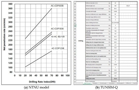
Figure 1.
Typical examples of the NTNU advance rate prediction model (Modified from [23]) and TUNSIM-Q.
The analysis of the construction time and advance rate in the TUNSIM; however, is available only for the excavation, without considering the rock supports and installations in the tunnel [28]. In addition, even though the rock properties such as the Rock Blastability Index (SPR of “SPRengbarhet” in Norwegian, rock blastability), Drilling Rate Index (DRI), and Vickers Hardness Number Rock (VHNR) that are produced from lab tests are used in the model, the effects of the rock mass quality, which is generally used in a tunnel by the Q-value or RMR, are not considered.
Thus, in this study, TUNSIM-Q, updated in 2009 [29,30] and based on project reports of NTNU [31,32], is used, where the effects of rock properties such as SPR, DRI, VHNR, as well as the rock mass quality in the Q-value, can be considered. In addition, the usual tunnel supports and various installation methods such as shotcrete, rock bolts, steel ribs, forepoling, water protection, and concrete lining, etc., were included in the updated model.
Meanwhile, the construction method of a Korean tunnel that is analysed for this study is different from the one of a Norwegian tunnel, which is the basis of the NTNU model, as well as for the tunnel sizes. For example, rock mass classification is conducted by the Q-value, and a concrete lining is installed for an extremely poor rock mass quality in Norway. On the other hand, the rock mass quality is classified by RMR, and a concrete lining is always installed for the whole length of a tunnel in Korea. Additionally, the amount and kinds of tunnel supports are different. Hence, the NTNU model is slightly modified for this study.
Initial SPR, DRI and VHNR are automatically given according to the rock mass quality (Q-value) in the Excel simulation sheets unless they are provided by the user, and the variation of Q-values in the model influences the initial SPR, round/drill length and others factors, as shown in Figure 2.
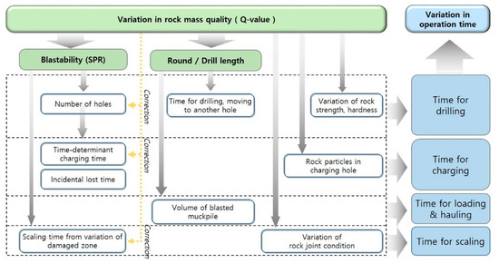
Figure 2.
Effects of rock mass quality variation in the NTNU model (Modified from [29]).
Scheme 3 needs to break the rock to a certain degree of fragmentation, where 50% of the blasted rock size is under 250 mm (d50 = 250 mm) [22]. Furthermore, the variation of SPR leads to the adjustment in time of the number of charge holes, time determinant charging time, incidental lost time, and scaling time. The variation in round/drill length results in an adjustment of the time for drilling and moving to the other holes, as well as the volume of the blasted muck pile.
The DRI is determined from the brittleness value, which is a measure of the rock resistance from repeated impacts until crushing, and the SJ value, which is a measure of the rock resistance to miniature drill penetration (surface hardness) [23]. The DRI affects the penetration rate of the charge holes and rock bolt holes in the model.
The Vickers Hardness Number (VHN) is used as a measure of the abrasiveness of each mineral. The mineral hardness numbers are combined to generate a hardness number for the rock VHNR according to the mineral percentages of the actual rock [33,34]. VHNR has an influence on the bit changing factor in drilling [23].
3. Tunnel Size and Support Types
The tunnel shapes and sizes used for the construction time analyses are presented in Figure 3, which are the standard tunnel cross-sections and tunnel support designs established by the Korean Ministry of Land, Infrastructure and Transport (MOLIT) in 2021. The design is for a tunnel with two lanes and consists of a total of five sizes and tunnel support types according to RMR. The tunnel widths and heights are between 10.5 and 10.7 m, and between 7.0 and 7.4 m, respectively, as shown in Table 1, which is summarised from MOLIT [35]. The allowed overbreak and drill length decreases from 19 cm to 12 cm, and from 3.8 m to 1.3 m, respectively, with lower RMR (higher tunnel support types).
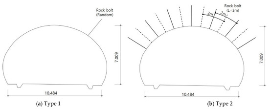
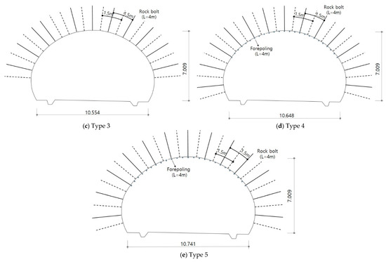
Figure 3.
Analysed tunnel size and support types (Modified from [35]).

Table 1.
Tunnel specifications by support type.
The kinds and number of tunnel supports increased from Tunnel Support Type 1 through 5, as presented in Table 2, summarised from [35]. In Tunnel Support Type 1, 5 cm of shotcrete and 3 m of rock bolts were randomly installed. For Type 1 through Type 3, only shotcrete and rock bolts were installed. For Tunnel Support Type 4, steel ribs or lattice girders were also installed with a 1.5 m interval, in addition to the shotcrete and rock bolts. For Type 5, forepoling was added to the tunnel supports used in Type 4. In Korea, a concrete lining of at least 30 cm thickness is installed for the whole length of a typical tunnel after the breakthrough of the tunnel or far behind the face.
Table 2.
Tunnel support specifications in Korea.
The rock mass quality in the updated NTNT D&B model is expressed by a Q-value; however, the tunnel sizes and support types vary with RMR. Hence, the RMR values in Table 2 are converted into Q-values by the relationship suggested by Bieniawski [36].
4. Classification of Construction Time
The construction time in this study is separated into five categories: basic, standard, gross, tunnel, and total according to tunnel support and operation types in Korea. Table 3 shows the definitions of these categories of construction time and the kinds of tunnel supports, as well as the operations for each construction time type.
Table 3.
Classification of construction time and operations in this study.
The basic construction time is the time spent on pure excavation operations such as drilling, charging, ventilation, loading and hauling, and scaling. The standard construction time includes the implementation of the usual tunnel supports to ensure tunnel safety such as shotcrete, rock bolts, forepoling, steel ribs, and injection (grouting), as well as the basic construction time in the NTNU model. The grouting operation time is excluded from this study since it is not included in the tunnel support types described in Table 2.
The gross construction time is the time spent on permanent or secondary tunnel supports after the tunnel breakthrough, in addition to the standard construction time. The pure gross construction time in this study consists of final scaling, water protection and concrete lining. The tunnel construction time is related to the installation operations inside the tunnel to finalise tunnel construction.
Lastly, the total construction time includes the site preparation time, portal excavation, and unforeseen rock conditions. Regarding this, Macias and Bruland [37] concluded that it would take 5–6 months for a tunnel start-up when using a new machine. Daller [2] mentioned that 3–4 months are needed for mobilisation, site installation and portal excavation. Accordingly, it is assumed in this study that the time required for site preparation, portal excavation, and demobilisation is 3 months (13.5 weeks), 2 weeks, and 1 week/km, respectively, based on values reported in previous studies and the author’s experiences. Furthermore, uncertainties in the geology and complexity of tunnel construction processes often result in construction delays and cost overruns [38]. Hence, for additional time due to unforeseen rock conditions, 7% of the standard construction time covering tunnel supports is recommended to be used in the NTNU model.
Meanwhile, advance rates are the tunnel length excavated during each construction time, excluding the tunnel, and total construction time.
5. Analysis and Results
The construction method of a Korean tunnel is different from the one of a Norwegian tunnel, not to mention tunnel sizes. For example, the rock mass classification is conducted by the Q-value, and a concrete lining is installed for extremely poor rock mass quality in Norway. On the other hand, the rock mass quality is classified by RMR, and a concrete lining is always installed for the whole length of a tunnel in Korea. Therefore, to consider the characteristics in the tunnelling practice of Korea, the analysis starts from the modification of TUNSIM-Q that was established based on a Norwegian tunnel specification.
The second step is to set up the tunnel sizes, such as the cross-sectional area, perimeter length of a tunnel, round length, etc., as well as the tunnel support types based on a Korean tunnel specification. The rock mass conditions such as SPR, DRI, and VHNR are set up according to the converted Q-value given for each tunnel support type.
The final step is to analyse the operation times for each tunnelling operation such as drilling, charging and blasting, shotcreting, and rock bolting, etc., for the standard Q-values given by each tunnel support type, followed by the basic, standard, gross, tunnel and total construction time by summing up the operation times corresponding to each construction time category and correction factors.
5.1. Construction Time with Tunnel Support Types
Table 4 shows the summary for rock and rock mass conditions for each tunnel support type that is given from the Korean government [35]. The Q-value is converted from RMR by this relationship [36] and the rock properties; SPR, DRI and VHNR are automatically given from the Q-value in this study.
Table 4.
Rock properties and rock mass conditions for each case.
When applying these conditions, as well as the tunnel and support conditions given in Table 1, Table 2, Table 3 and Table 4, the construction time determined from the NTNU D&B model is presented in Table 5 and Figure 4a.
Table 5.
Construction time and advance rates with tunnel support types.
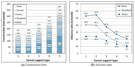
Figure 4.
Construction time and advance rates with tunnel support types.
Table 6 shows the operation time for each specific operation and how the basic, standard and gross operation times result from each operation time. Each operation time is the time needed to perform the operation during one blasting round, and thus the time unit used is minutes. The subtotal time in hour for one whole tunnel length (3 km) is calculated by the subtotal time (min) of one round/60 (min) × 3000 m/round length (m), as indicated in Table 5.
Table 6.
Breakdown of each operation time.
In Figure 4a, the numbers inside each bar in the chart indicate the ratios of the respective construction times to the total construction time, and the numbers above each bar indicate the total construction times.
The results show that the basic construction time, i.e., the pure excavation time not considering tunnel supports, increases from about 57 weeks to 146 weeks for a 3 km tunnel with a variation of tunnel support types from type 1 to type 5, except for type 2. Despite the higher number of holes drilled in Type 2 (96 holes) than Type 1 (88 holes), the reason that more basic construction time is needed in Type 1 is mainly because the drilling rate in Type 1 (177 cm/min) is slower than that in Type 2 (198 cm/min) due to the very hard rock mass quality, even though the drill length is the same for the two types. In other words, the drill times in Types 1 and 2 are 144 and 118 min, respectively, as shown in Table 6. The ratios of the basic construction time to the total construction time increase from 34% to 40% with higher tunnel support types, as the round length decreases considerably from 3.5 m for Type 1 to 1.2 m for Type 5, even though the round cycle time needed for one blasting round, excluding the tunnel supports, decreases slightly from 482 min to 426 min with higher tunnel support types; in turn, the basic construction time (= round cycle time × tunnel length/round length) increases.
For the standard construction time, which includes the usual tunnel supports such as shotcrete and rock bolts, etc., in addition to the basic construction time, the time gradually increases from 74 weeks to 259 weeks with higher support types, and more time is needed for Type 2 than Type 1, unlike the basic construction time. The ratio of the standard operation time increases from 10% to 31% with higher tunnel support types (Figure 4a), which is attributed to the increase in the kinds and amount of tunnel supports, as indicated in Table 2. In addition, the standard advance rate, which is generally used as the usual advance rate of a D&B tunnel, decreases from 40.8 m/week to 11.6 m/week with the variation of support types from Type 1 to Type 5 (Figure 4b), corresponding to 6.8 m/day for Type 1 and 1.9 m/day for Type 5 because there are assumed to be six working days per week (Table 3) in this study. This means that 1.9 and 1.6 blasting rounds can be performed during one day for Types 1 and 5, respectively. For Type 3, in which the round length is 2 m, however, the standard advance rate is 25.6 m/week, i.e., 4.3 m/day, which corresponds to more than two blasting rounds per day. In connection with this, Kim et al. [21] investigated the blasting cycle time (the time spent for one blasting round including the usual tunnel supports) for three Korean tunnels and the results showed that the typical cycle time for Type 3 was approximately 8 h. Hence, it is thought that the advance rate determined in this study is within a reasonable range.
The gross construction time covers the operation time for final scaling, water protection and concrete lining in addition to standard construction time, and the gross operation time accounts for between 30% and 14%, decreasing with increasing tunnel support types since little variation occurs in the gross operation time (Table 6), 50 weeks for all the types, but the total construction time increases.
The tunnel construction time consists of pavement and various installations in the tunnel, in addition to the gross construction time. It is found that the tunnel operation time excluding the gross construction time is approximately 20 weeks, almost the same for all the tunnel support types, taking between 12% and 5% of total construction time.
Lastly, the total construction time covering all the operations, site preparations, and unforeseen rock conditions, etc. (at least 7% of the standard construction time is recommended in the NTNU model), is between 167 and 365 weeks, which corresponds to between 3.8 and 8.2 years, provided that one year is 44 weeks. This means that total construction time of a tunnel of very poor rock mass quality is more than twice that of a tunnel of very good rock mass quality for the same tunnel length.
Meanwhile, Table 6 shows a breakdown of the basic, standard and gross operation times. For Type 1, it is found that the operation in which the most time is taken is drilling (144 min), due to the very hard rock mass quality, followed by loading and hauling (129 min) because of the longest round length of Type 1. The rig time is the time needed to move the drilling jumbo to the face, and connect and disconnect the power supply and water, etc. The incidental lost time for drilling and blasting covers the technically dependent lost time occurring at random during tunnelling operations, e.g., machine breakdown, which is assumed to be 10% of the total operation time in the NTNU model [23]. The correction factor for tunnel length and job training is used to consider the variation in operation time resulting from the efficiency in operations according to excavated tunnel length, which is 1 for 3 km tunnel length, i.e., no additional time, as can be seen in Figure 5.
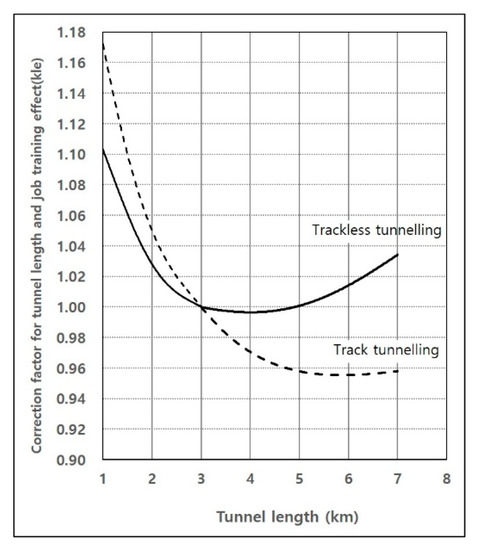
Figure 5.
Correction for tunnel length and job training (Modified from [23]).
Regarding the tunnel support operations, shotcrete is generally placed all at once for small thickness, on the other hand, twice or three times in small thickness in the case of large thickness. Hence, much time is required to place shotcrete for Type 1 due to a long round length (3.5 m and a thickness of 14.3 cm including the overbreak and rebound) as well as for Type 5 due to a great thickness (22 cm including the overbreak and rebound). Furthermore, for Type 1, rock bolts are installed randomly when necessary, which are quantified into two bolts per 3.5 m round length [33], and it takes an average of 20 min per round to install the bolts. The operation time for the steel rib/lattice girders installed in Type 4 and Type 5 is, on average, 45 min per round, and the forepoling installed in Type 5 only takes an average of 44 min per round for the given conditions in the NTNU model. Finally, it is estimated that the total operation time for the tunnel supports is only between 144 min and 330 min per round, which corresponds to 17 weeks and 113 weeks, respectively, for the whole length of the tunnel.
Furthermore, it is shown that the operation time of the final scaling, water protection and concrete lining that are included in the gross construction time of 50 weeks is almost the same for all the types.
5.2. Construction Time with Mixed Geological Conditions
In the actual tunnelling, the geological condition is not identical for the whole tunnel length; rather, the geological types vary from a soft rock or soil to a hard rock. Hence, based on the study on the effects of the five different tunnel supports varied with the Q-value on the construction time in Section 5.1, three cases (Table 7) representing mixed geological conditions are analysed. Figure 6 shows a typical example for the ratios given in Table 7. Case A, a good condition, consists of 20%, 30%, 30%, 10%, and 10% of the 3 km tunnel lengths for Types 1, 2, 3, 4, and 5, respectively, which are given in Table 2, where a favourable rock mass quality of over 60 in RMR forms 50% of the length, assuming that the tunnel excavation is carried out in the geological conditions presented in Figure 6. In Case B, the tunnel support types in medium geological conditions are made up of 10%, 25%, 30%, 25%, and 10%, respectively. In Case C, a bad geological condition, the distribution of the support types is 10%, 10%, 30%, 30%, and 20%, respectively, and a rock mass quality of below 40 in RMR forms 50% of the tunnel length.
Table 7.
Assumed ratio and tunnel length for each tunnel support type.
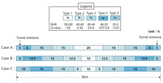
Figure 6.
Typical example of the ratios of tunnel support types for analysed cases.
Meanwhile, the terms used to define the geological condition of a tunnel in this study, i.e., good, medium or bad conditions, are only qualitative expressions, which leave ambiguity as to how good or bad these conditions are. Hence, a quantitative term, equivalent to the rock mass quality (ERQ), is suggested with Equation (1) to express the overall rock mass condition of a tunnel:
where n is the number of total tunnel sections, Li is the length of each tunnel section (m), RMRi or Qi represents RMR or Q for each tunnel section, and Lt is whole tunnel length (m).
If ERQ is applied to this study, the overall rock mass quality of Cases A, B and C become 58, 50 and 42, respectively, based on RMR in Table 4 and the length of each tunnel section in Table 7.
The analyses show that basic construction times for Cases A, B and C are 77, 85, and 97 weeks, respectively, and account for 36–38% of total construction time, as shown in Figure 7a. Additionally, the basic construction time of Case C in bad geological conditions increases by 26% compared to Case A under good conditions (Table 8), meaning that the time spent for basic operations (pure excavation), excluding tunnel supports, increases by 26% when the geology worsens from good to bad conditions.
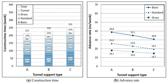
Figure 7.
Construction time and advance rates by case.
Table 8.
Construction time and advance rates by case.
The increase ratio in the standard operation time is 18% and 48% for Case B and Case C, respectively, compared to Case A, which is much more than the ratio in the basic operation time. This is because the increased ratio of the standard operation time with higher tunnel support types is much more than the ratio of the basic operation time. In other words, as shown in Table 5, the basic operation time for Type 5 increases 2.6 times (= 146 weeks/57 weeks) relative to that of Type 1; on the other hand, the standard operation time for the Tunnel Support Type 5 increases 6.6 times relative to that of Type 1. This means that although the ratio of the basic operation time to the total construction time, i.e., 34–40% (Figure 4a), is generally more than that of standard operation time (10–31%), the increase ratio of the standard operation time is far more than that of the basic operation time, with an increasingly poor rock mass quality. Meanwhile, the standard advance rate that is usually used as the advance rate of a D&B tunnel, shows about 26, 23, and 20 m/week for Cases A, B, and C, respectively (Figure 7b), corresponding to 4.3 m/day (=25.9 m/6 days), 3.8 m/day (=23.0 m/6 days), and 3.3 m/day (19.5 m/6 days) for good (Case A), medium (Case B) and bad rock mass quality (Case C), respectively. This implies that the advance rate of a D&B for a bad rock mass quality tunnel decreases by 25% compared to those of a tunnel with a good rock mass quality, even though this ratio can be varied with given geological conditions, tunnel sizes and operation conditions.
Regarding the gross operation time and the tunnel operation time, it is found that the variation in time with a worsening rock mass quality is almost 0 since the variation in the operation time of final scaling, water protection, and concrete lining in the gross operation time, as well as roadway construction and the installation of electricity, etc., in the tunnel operation time, is hardly related to geological conditions, as can be seen in Table 8.
Lastly, it is shown that total construction time for Case A is 212 weeks and increases to 8% or 19% compared to Case A with worsening geological conditions. Furthermore, when considering that the ERQ of Case B is 52, the total construction time of Case B (228 weeks) shows a similar level to Type 3 (214 weeks) in Table 5, of which the RMR is 50.
6. Conclusions
This paper analyses the construction time and advance rate of a 3 km long D&B tunnel under various geological conditions using an upgraded NTNU drill and blast prediction model. The analysis was carried out for the five types of Korean tunnel supports according to rock mass quality, ranging from Type 1 (very good rock mass quality) through to Type 5 (very poor rock mass quality), and four kinds of rock properties, as well as the rock mass quality for each tunnel support type, were applied to simulate different geological conditions based on the previous studies and the NTNU model.
The construction time was classified into five categories: basic, standard, gross, tunnel and total, according to the characteristics of the operations for a more effectively analysis of the construction times; the standard construction time covers not only the operations for excavation, such as drilling, charging, loading and hauling, etc., but also usual the tunnel supports such as shotcrete and rock bolts, etc., In addition, to properly consider the actual geological conditions in tunnelling, the construction times for the three mixed geological cases were analysed.
The primary conclusions of the study are summarised below:
(1) The ratio of the basic construction time to total construction time increases from 34% to 40% with the increasing tunnel support type. Despite the greater number of drill holes in Type 2 (96 holes) relative to Type 1 (88 holes), the reason for a more basic construction time in Type 1 is mainly that the drilling rate in Type 1 (177 cm/min) is slower than that in Type 2 (198 cm/min) due to the very hard rock mass quality, even though the drill length is the same for the two types.
(2) The ratio of the standard operation time for the operations of the usual tunnel supports to total construction time increases from 10% to 31% with a worsening rock mass quality, which is attributed to the increase in the kinds and amounts of tunnel supports. In addition, the standard advance rate that is generally used as the usual advance rate of a D&B tunnel decreases from 40.8 m/week to 11.6 m/week with the variation of support types from Type 1 to Type 5, which correspond to 6.8 m/day for Type 1 and 1.9 m/day for Type 5; it is assumed that there are six working days per week in this study. This means that 1.9 and 1.6 blasting rounds can be performed during one day for Types 1 and 5, respectively.
(3) The gross construction time covers the operation time for the final scaling, water protection and concrete lining, in addition to standard construction time. The gross operation time accounts for between 30% and 14%, decreasing with the increase in the tunnel support types since little variation occurs in the gross operation time (50 weeks for all the types) but the total construction time increases.
(4) The total construction time covering all the operations, site preparations, and unforeseen rock conditions, etc., is between 167 and 365 weeks, which corresponds to between 3.8 and 8.2 years, provided that one working year is considered to be 44 weeks. This means that the total construction time of a tunnel in a very poor rock mass quality is more than twice that of a tunnel in very good rock mass quality for the same tunnel length.
(5) Three cases representing mixed geological conditions, i.e., Case A (good geological conditions; 20%, 30%, 30%, 10%, and 10% of a 3 km tunnel length for Tunnel Support Types 1, 2, 3, 4, and 5, respectively); Case B (medium geological conditions; 10%, 25%, 30%, 25%, and 10%, respectively) and Case C (bad geological conditions; 10%, 10%, 30%, 30%, and 20%, respectively) were also analysed. The results show that the standard advance rate is 26, 23 and 20 m/week for Cases A, B and C, respectively, and the total construction time for Case A is 212 weeks and increases to 8% or 19% compared to Case A with worse geological conditions.
(6) A quantitative term, equivalent rock mass quality (ERQ), is suggested in this study to intuitively express the overall rock mass condition of a tunnel. The total construction time of Case B (228 weeks) in the ERQ of 52 shows a similar level to the Tunnel Support Type 3 (214 weeks), of which RMR is 50.
Author Contributions
Conceptualisation, Y.K.; validation, S.S.L.; formal analysis, Y.K.; data curation, Y.K.; writing—original draft preparation, Y.K.; writing—review, S.S.L.; supervision, S.S.L.; project administration, Y.K. and S.S.L.; funding acquisition, Y.K. and S.S.L. All authors have read and agreed to the published version of the manuscript.
Funding
This research was funded by the Korean Agency for Infrastructure Technology Advancement (KAIA).
Institutional Review Board Statement
Not applicable.
Informed Consent Statement
Not applicable.
Data Availability Statement
The study did not report any data.
Acknowledgments
This work is supported by the Korea Agency for the Infrastructure Technology Advancement (KAIA) grant funded by the Ministry of Land, Infrastructure and Transport (Grant 21CTAP-C163775-01).
Conflicts of Interest
The authors declare no conflict of interest. The funders had no role in the design of the study; the collection, analyses, or interpretation of data; the writing of the manuscript; or the decision to publish the results.
References
- Hoek, E. Big tunnel in bad rock. J. Geotech. Geoenviron. 2001, 127, 726–740. [Google Scholar] [CrossRef]
- Daller, J. Selection of Construction Methods in Rock Tunneling. In Proceedings of the 11th International Tunnelling and Underground Structures Conference, Ljubljana, Slovenian, 23 November 2017; pp. 51–57. [Google Scholar]
- Lislerud, A. Hard Rock Tunnel Boring: Prognosis and Costs. Tunn. Undergr. Space Technol. 1988, 3, 9–17. [Google Scholar] [CrossRef]
- Nelson, P.; O’Rourke, T.D.; Kulhawy, F.H. Factors Affecting TBM Penetration Rates in Sedimentary Rocks. In Proceedings of the 24th US Symposium on Rock Mechanics, College Station, TX, USA, 20–23 June 1983; pp. 227–237. [Google Scholar]
- Bamford, W.F. Rock Test Indices Are Being Successfully Correlated with Tunnel Boring Machine Performance. In Proceedings of the 5th Australian Tunneling Conference, Melbourne, Australia, 22–24 October 1984; Volume 2, pp. 9–22. [Google Scholar]
- Hughes, H.M. The relative cuttability of coal-measures stone. Min. Sci. Technol. 1986, 3, 95–109. [Google Scholar] [CrossRef]
- Boyd, R.J. Hard rock continuous mining machine: Mobile Miner MM-120. In Rock Excavation Engineering Seminar; Howarth, D.F., Ed.; Department of Mining and Metallurgical Engineering, University of Queensland: Brisbane, Australia, 1986. [Google Scholar]
- Innaurato, N.; Mancini, R.; Rondena, E.; Zaninetti, A. Forecasting and effective TBM performances in a rapid excavation of a tunnel in Italy. In Proceedings of the Seventh International Congress ISRM, Aachen, Germany, 16 September 1991; pp. 1009–1014. [Google Scholar]
- Sundin, N.O.; Wanstedt, S. A boreability model for TBM’s. Rock Mechanics Models and Measurements Challenges from Industry. In Proceedings of the 1st North American Rock Mechanics Symposium; Austin, TX, USA, 1–3 June 1994, Nelson, P., Laubach, S.E., Eds.; The University of Texas at Austin: Austin, TX, USA; Balkema: Rotterdam, The Netherlands, 1994; pp. 311–318. [Google Scholar]
- Rostami, J. Design Optimization, Performance Prediction and Economic Analysis of Tunnel Boring Machine for the Construction of the Proposed Yucca Mountain Nuclear Waste Repository. Master’s Thesis, Colorado School of Mines, Golden, CO, USA, 1993. [Google Scholar]
- Bruland, A. Hard Rock Tunnel Boring. Ph.D. Thesis, Norwegian University of Science and Technology, Trondheim, Norway, 1998. [Google Scholar]
- Barton, N. TBM performance in rock using QTBM. Tunnels Tunnell. Int. 1999, 31, 41–48. [Google Scholar]
- Girmscheid, G.; Schexnayder, C. Drill and blast tunneling practices. Pract. Period. Struct. Des. Constr. 2002, 7, 125–133. [Google Scholar] [CrossRef] [Green Version]
- European Commission. Annex 13 of Assessment of Unit Costs (Standard Prices) of Rail Projects (CAPital EXpenditure); European Commission: Brussels, Belgium, 2018. [Google Scholar] [CrossRef]
- Putzmeister. Available online: http://bestsupportunderground.com/tbm-drill-and-blast/?lang=en (accessed on 31 July 2021).
- Einstein, H.; Indermitte, C.; Sinfield, J.; Descoeudres, F.; Dudt, J.-P. Decision Aids for Tunneling. Transp. Res. Rec. 1999, 1656, 6–13. [Google Scholar] [CrossRef]
- Einstein, H. The decision aids for tunnelling(dat)—A brief review. Mag. Korean Tunn. Undergr. Space Assoc. 2001, 3, 37–49, ISSN 2233-7482. [Google Scholar]
- Špačková, O.; Šejnoha, J.; Straub, D. Probabilistic assessment of tunnel construction performance based on data. Tunn. Undergr. Space Technol. 2013, 37, 62–78. [Google Scholar] [CrossRef] [Green Version]
- Nataadiningrat, B.B.; Prabowo, A.W.; Rasmawan, I.M.A.B.; Putri1, A.T.; Abduh, M.; Wirahadikusumah, R.D. Analysis of NATM tunneling method using CYCLONE modeling and simulation tools. IOP Conf. Ser. Mater. Sci. Eng. 2020, 933, 012002. [Google Scholar] [CrossRef]
- Periku, E.; Algest, A. Construction time analysis for different steps in drill-and-blast method of hydro power tunnel excavation. Int. J. Eng. Res. Appl. 2015, 5, 95–101. [Google Scholar]
- Kim, Y.; Kim, H.; Lee, S.S. An analysis of excavation cycle time for Korean tunnels and the comparison with the Standard of Construction Estimate. J. Korean Tunn. Undergr. Space Assoc. 2019, 21, 137–153. [Google Scholar] [CrossRef]
- NTNU. Report 2A-05 Drill and Blast Tunnelling-Blast Design; NTNU, Department of Civil and Transport Engineering: Trondheim, Norway, 2007. [Google Scholar]
- NTNU. Report 2B-05 Drill and Blast Tunneling-Advance Rate; NTNU, Department of Civil and Transport Engineering: Trondheim, Norway, 2007. [Google Scholar]
- NTNU. Report 2C-05 Drill and Blast Tunneling-Cost; NTNU, Department of Civil and Transport Engineering: Trondheim, Norway, 2007. [Google Scholar]
- Norwegian Tunnelling Society. Norwegian Tunnelling; Publication No. 14; Norwegian Tunnelling Society: Oslo, Norway, 2004. [Google Scholar]
- Zare, S. Prediction Model and Simulation Tool for Time and Costs of Drill and Blast Tunnelling. Ph.D. Thesis, Norwegian University of Science and Technology, Trondheim, Norway, 2007. [Google Scholar]
- Zare, S.; Bruland, A.; Rostami, J. Evaluating D&B and TBM tunnelling using NTNU prediction models. Tunn. Undergr. Space Technol. 2016, 59, 55–64. [Google Scholar]
- Zare, S.; Bruland, A. Progress of Drill and Blast Tunneling Efficiency with Relation to Excavation Time and Costs; ITA World Tunnel Congress: Prague, Czech, 2007; pp. 805–809. [Google Scholar]
- Kim, Y.; Bruland, A. Effect of rock mass quality on construction time in a road tunnel. Tunn. Undergr. Space Technol. 2009, 24, 584–591. [Google Scholar] [CrossRef]
- Kim, Y. Tunnel Contour Quality Index in a Drill & Blast Tunnel. Ph.D. Thesis, Norwegian University of Science and Technology, Trondheim, Norway, 2009. [Google Scholar]
- NTNU. Report 2E-95 Tunelling Road Tunnels-Completion and Installations; NTNU, Department of Building and Transport Engineering: Trondheim, Norway, 1996; pp. 10–148. (In Norwegian) [Google Scholar]
- NTNU. Report 2F-99 Tunnelling Unit Time System for Excavation, Rock Support and Installations; NTNU, Department of Civil and Transport Engineering: Trondheim, Norway, 2000. (In Norwegian) [Google Scholar]
- Bruland, A. Report 13A-98 Drillability Test Methods; NTNU, Department of Civil and Transport Engineering: Trondheim, Norway, 1998. [Google Scholar]
- Adebayo, B.; Okewale, I.A. Analysis of the potential of some Nigerian rocks to wear drill bit. AU J. Technol. 2007, 11, 1–5. [Google Scholar]
- MOLIT (Ministry of Land, Infrastructure and Transport of Korea). Practical Design Tips for the Construction of National Roadway; MOLIT: Sejong City, Korea, 2021.
- Bieniawski, Z.T. Rock Mechanics Design in mining and Tunneling; Balkema: Rotterdam, The Netherlands; Boston, MA, USA, 1984; ISBN 13:978-9061915072. [Google Scholar]
- Macias, F.J.; Bruland, A. D&B versus TBM: Review of the Parameters for a Right Choice of the Excavation Method. In Proceedings of the ISRM Regional Symposium-EUROCK, Vigo, Spain, 27–29 May 2014. [Google Scholar]
- Mahmoodzadeh, A.; Mohammadi, M.; Abdulhamid, S.N.; Ibrahim, H.H.; Ali, H.F.H.; Salim, S.G. Dynamic reduction of time and cost uncertainties in tunneling projects. Tunn. Undergr. Space Technol. 2021, 109, 103774. [Google Scholar] [CrossRef]
- NGI. Using the Q-system: Handbook; NGI: Oslo, Norway, 2015. [Google Scholar]
Publisher’s Note: MDPI stays neutral with regard to jurisdictional claims in published maps and institutional affiliations. |
© 2021 by the authors. Licensee MDPI, Basel, Switzerland. This article is an open access article distributed under the terms and conditions of the Creative Commons Attribution (CC BY) license (https://creativecommons.org/licenses/by/4.0/).