Abstract
Research in the process of internal combustion engines shows that their efficiency can be increased through several technical and functional solutions. One of these is turbocharging. For certain engine operating modes, the available energy of the turbine can also be used to drive an electricity generator. The purpose of this paper is to highlight the possibilities and limitations of this solution. For this purpose, several investigations were carried out in the virtual environment with the AMESim program, as well as experimental research on a diesel engine for automobiles and on a stand for testing turbochargers (Turbo Test Pro produced by CIMAT). The article also includes a comparative study between the power and torque of the naturally aspirated internal combustion engine and equipped with a hybrid turbocharger. The results showed that the turbocharger has a very high operating potential and can be coupled with a generator without decreasing the efficiency of the turbocharger or the internal combustion engine. The main result was the generation of electrical power of 115 W at a turbocharger shaft speed of 140,000–160,000 rpm with an electric generator shaft speed of 14,000–16,000 rpm. There are many constructive solutions for electrical turbochargers with the generator positioned between the compressor and the turbine wheel. This paper is presenting a solution of a hybrid turbocharger with the generator positioned and coupled with the compressor wheel on the exterior side.
1. Introduction
Research in the process of internal combustion engines shows that their efficiency can be increased through several technical and functional solutions. After preliminary investigations of the performance of engines equipped with advanced axial turbocharger turbines [1,2], it was considered that turbochargers have a huge development potential. Hybrid power trains for city cars were also developed in tight contact with turbocharger systems [3]. Furthermore, these applications were made for hybrid city cars [4]. The center development area was the turbocharger, which was tested with experimental and CFD calculation for better performances optimization [5].
Relatively recently, the idea that exhaust gases from the tailpipes of internal combustion engines can be used as an energy source has been advanced. Normally, a turbocharger has the role of helping to introduce a greater amount of fresh air into the cylinders of an engine and at the same time to reduce emissions [6]. Moreover, they can be used to produce electricity. In the literature there are very few references to this technology, which seems to have been used since 2012, in the case of a Jaguar XJR-15 equipped with YGK EER-Hybrid system [7]. A similar system was used by Mercedes for the AMG Project One Formula 1 model. The electric flue gas turbocharger used an excessive part of the flue gas flow to generate electricity as an alternator and to store it either by recovery in the high voltage lithium-ion battery or to transmit it as additional propulsion to another electric motor [8]. This process of energy recovery through the turbocharger and the scientific works dealing with this aspect is presented in [3]. This technology has also been applied to natural gas marine engines [9].
The aim of this paper is to present the results of the experimental research of a hybrid turbocharger, simulating and validating the new solution for increasing the energy performance of the internal combustion engine through hybrid turbochargers using a coupled electric generator. The simulation will be performed using AMESim software developed by Siemens and the test will be performed using a diesel internal combustion engine with a cylinder capacity of 1.9 L. The article also includes a comparative study between the power and torque of the naturally aspirated internal combustion engine equipped with a hybrid turbocharger.
The main focus in this work lies in affirming the electrical energy generation from the exhaust gasses of the internal combustion engine through the turbocharger and showing the great exploitation potential of the turbocharger (which has a high mechanical efficiency).
There are many constructive solutions for electrical turbochargers with the generator positioned between the compressor and the turbine wheel [10]. This paper presents a solution of a hybrid turbocharger with the generator positioned and coupled with the compressor wheel on the exterior side. This is a much better solution since the solution with an electric generator placed between the compressor and the turbine is blocked due to the heat transfer from the turbine (this being an unreliable constructive solution). This electric turbocharger solution is used to recover energy as well as to increase the efficiency of the internal combustion engine system [11].
Another problem implicitly solved by this constructive solution is the significant decrease of the vibration of the compressor and the turbine system. The vibration of the turbine rotor and compressor wheel was stabilized by the external fixing points by coupling with gear ratio and also by the generator [12].
2. Turbocharging Principles
If a turbocharger is attached to an internal combustion engine, then the cycle efficiency increases compared to that of the naturally aspirated engine. Figure 1 shows the mixed turbocharged cycle [13].
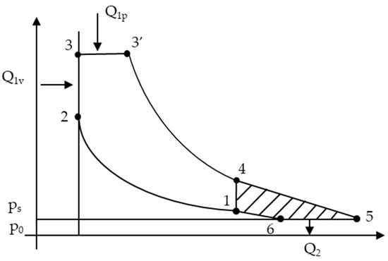
Figure 1.
Mixed turbocharged cycle [14].
In this case, the flue gas energy (area 1-4-5-6-1) is used to drive a compressor. Prolonged expansion (4-5) is achieved in the blade network of the turbine, which drives the compressor. The air is compressed (6-1) to the pressure ps. So, the pressure and density of the air in the cylinder will increase [15,16]. As a result, a larger amount of air will enter the engine cylinders, compared to the naturally aspirated one and, consequently, more fuel can be introduced into the combustion chamber. The result would be more energy per engine displacement unit [17].
The mechanical losses in the turbocharger are lower than those recorded in the case of prolonged expansion in the engine cylinders. Increasing the air pressure allowed in the supercharged engine cylinders leads to a maximum pressure per cycle of 30–40% [18,19]. Increasing the system components raises the engine mechanism’s requirements (engine block, cylinder head, piston, bolt, connecting rod, crankshaft) [20,21,22]. Due to the higher air temperature, which is retained in the cylinders at the end of the intake process, there is also an increase in the thermal regime (maximum temperature per cylinder) and the thermal stresses of the pistons, valves, and vanes of the tubing rotor [23,24]. The reduction of the thermal regime can be obtained by cooling the forced air from the compressor (intercooler), changing the distribution phases (increasing the crossing angle of the valve opening), and increasing the air flow on the cycle [25,26].
A surge occurs when high internal combustion engine speeds are used and may stall the turbocharger [27]. The transient operation of turbocharged diesel engines has also been associated with poor driving as well as gaseous emissions [28]. It is well known that the turbocharger contributes to an optimized combustion process for the engine [29]. Also, the transient operation is mostly optimized in the light of response and provides the demanded torque above the maximum torque generated by a natural aspired engine [30]. The difference in time from the boosted torque and the maximum torque provided by the natural aspired engine is known as turbo-lag; this can be another problem of the turbocharger [31].
Research showed that power and torque can be improved by 30–50% by turbocharging internal combustion engines compared to those naturally aspirated. Therefore the fuel consumption is reduced by 15–25% [32].
Since car engines operate in a wide range of speeds and loads, it is necessary to provide the turbocharger with the motor for critical speeds (low speeds and loads) [33]. For the other operating modes (maximum power and speed) it is possible to use a turbine with variable geometry or the solution through which a part of the exhaust gases to bypass the turbine (bay-pass valve), which results in a decrease of the available energy [34]. This involves providing the turbocharger with the engine for the range of speeds characteristic of the maximum torque, and for those specific to the maximum speed the excess energy available in the flue gas to be harnessed by generating electricity using a generator connected in series with the turbocharger shaft [35,36].
Another method to determine some turbocharger parameters is the acoustic method [37]. With this method the performance over the axial inflow turbocharger turbine can be evaluated [38]. Some diesel turbocharger engines have failure diagnosis, which can be also analysed with the acoustic method. Therefore, it is very efficient [39]. After obtaining the parameter result, more aerodynamic designs can be optimized [40]. The new optimized design evaluation shows a higher turbocharger efficiency [41].
3. Materials and Methods
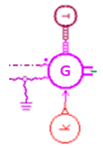
The configuration of the hybrid cogenerator hybrid turbocharger is as follows (Figure 2):
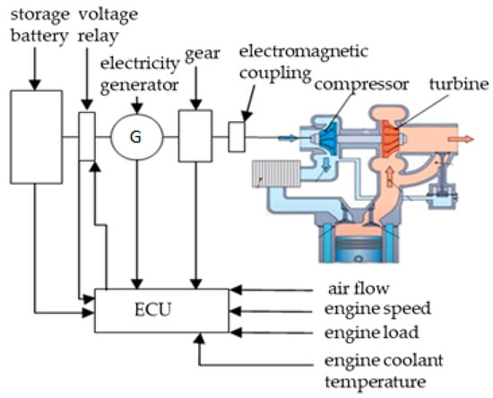
Figure 2.
The structure of the hybrid turbocharger design [42].
- Turbocharger: drive shaft electric generator;
- Electromagnetic coupling (electrically controlled);
- Gear, ratio 1:10;
- Electricity generator;
- Voltage regulator;
- Battery pack;
The technical specification of the electrical generator has a nominal speed of 10,000 rpm, but we used an overstressed mode for the electrical generator at a speed of 16,000 rpm for a short interval of time (0–20 s).
Table 1 contains all the important components of the hybrid turbocharger, such as the turbocharger components, gear ratio (1:10), and the 100 W electrical generator, as well as with the main symbols used by the simulation with AMESim software.

Table 1.
Main component parts of the hybrid turbocharger.
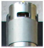
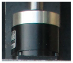
This conception was concretized by physical (Figure 3) and virtual (Figure 4) models that were tested in laboratories.
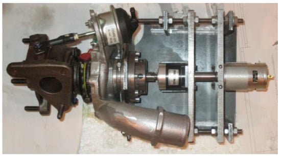
Figure 3.
Real construction of the hybrid turbocharger.
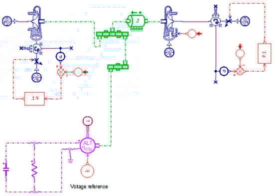
Figure 4.
Overview of hybrid turbocharger components with AMESim software.
The used turbocharger presented in Figure 3 is a 72 trim turbocharger with 0.35 A/R without variable geometry and without cooling fluid.
Details on the theoretical and experimental investigations, as well as the resulting conclusions, are summarized in the following chapters.
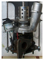
In Figure 5, the hybrid turbocharger connected to compressed air of the CIMAT Turbo Test Pro can be seen.
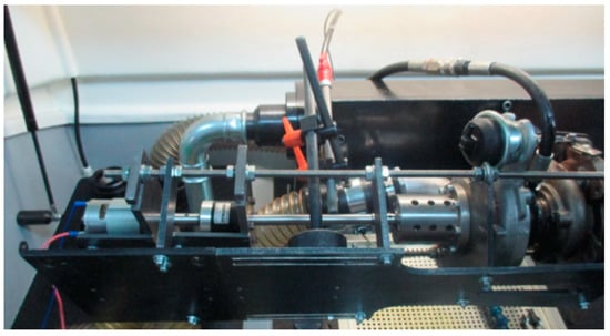
Figure 5.
The hybrid turbocharger connected to compressed air of the CIMAT Turbo Test Pro.
The operating principle of this hybrid turbocharger cogenerator of electrical energy can be found in the development of marine ship engines. The turbocharger applied for the ship engines is one with axial blades on the exhaust gas side and radial blades on the compressor side. Mitsubishi Heavy Industries, Ltd. (MHI), Tokyo, Japan developed the MET83MAG hybrid turbocharger for a marine ship diesel engine equipping the Shin Koho marine ship, which represents its first application worldwide [43]. The application presented in this article is intended for automotive internal combustion engines. This approach is also feasible and sustainable for automotive internal combustion engines.
The operation limits for an internal combustion engine with spark ignition equipped with a hybrid turbocharger are the same as by a diesel engine [44].
3.1. Stand Testing of Generator Hybrid Turbocompressor Equipment
To validate the functional characteristics of the new concept, subsystems were designed such as the coupling shaft between the turbocharger and the electricity generator, the reducer, and the generated electricity measurement system. The physical model was experimentally subjected to a stand for testing the CIMAT turbocharger (Figure 5). This allows for the evaluation of the functional characteristics of the compressed air-driven turbocharger at pressures of 0.1… 0.2 MPa, which replaces the flue gas flow discharged from the cylinders of the internal combustion engine [45].
The research undertaken under the stabilized regime allowed the evaluation of the following functional parameters of the system (Table 1):
- Compressed air pressure intended to drive the turbine;
- Speed of the turbocharger shaft of the electricity generator;
- Voltage and current values (excitation and load) of the generated electric current.
The experimental investigations, undertaken on the stand dedicated to the diagnosis of turbochargers, allowed us to obtain technical data which ensured the evaluation of the following dependencies:
- The speed variation of the turbocharger rotor over time (Figure 6). The start-up time of the turbine is 3.2 s, and the maximum rotational velocity of the shaft is 160,000 rpm;
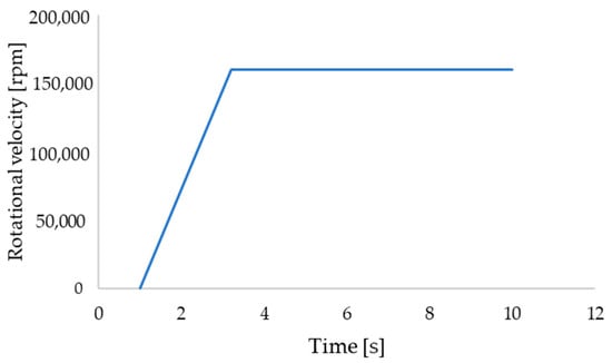 Figure 6. Turbocharger shaft speed variation (experimental result).
- 2.
- The variation, over time, of the current voltage and the power developed by the electric generator (Figure 7); the voltage resulting from the experimental work in relation to the time has the value from 0 to 23 Volts; the current intensity resulting from the experiments range between 0 and 4.5 Amperes; and the electrical power ranges from 0 to 102 Watts.
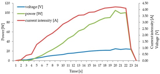 Figure 7. Time dependence of current, voltage current, and power generated by the hybrid turbo-charger (experimental result).
Analog measuring devices and appropriate calculation programs were used to determine the electrical measurements of the generator (Figure 8).
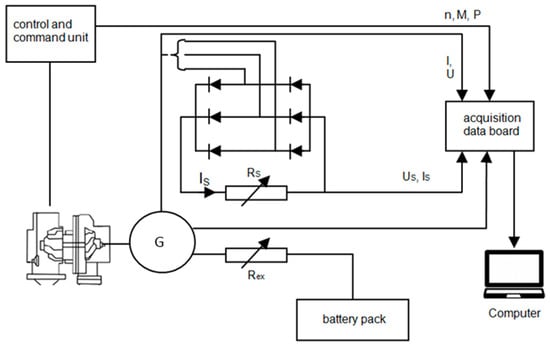
Figure 8.
Diagram of the exhaust system [46].
Table 2 indicates the resulting parameters, namely the evaluated parameter, the unit of measurement, and the value of the parameter.
Table 2.
The resulting parameters.
The conclusions formed from the tests are the following:
- The concept of hybrid turbocharger works feasibly;
- The turbocharger shaft speed is positioned in the interval from 140,000–160,000 rpm and due to the mechanical reducer/gear ratio 1:10, the electric generator shaft speed is 14,000–16,000 rpm;
- The electric generator (XD-3420) can be driven by the turbinel it generates energies of 0.67–0.68 Wh in approximate 21 s of the proved experimental phase, depending on the values of pressure and compressed air flow in the turbine blades;
- An electromagnetic coupling controlled by an electronic processor must be inserted between the turbocharger and the speed reducer;
In order to study in the virtual environment and the variation of the functional parameters of the designed system, a model was designed that was tested with AMESim software [45,47].
3.2. The Mathematical Model of the Electric Hybrid Turbocompressor
The evaluation of the energy performance of internal combustion engines can be performed based on the power supplied after the combustion of the fuel mixture in the cylinders. By increasing the air pressure in the cylinders and the amount of fuel injected per cycle, they can be increased. The effect of overfeeding on efficiency can be estimated based on the analysis of the ideal cycle and that can be seen in Figure 1 [48].
In this sense, according to the laws 1 and 2 of thermodynamics considering an isolated system (which does not lose mass, in the ideal case) and which evolves from 1 to 2, the following can be written (Figure 9):
where:
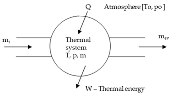
Figure 9.
Configuration of the thermal machine analysis system.
The turbine and compressors usually are considered open systems and transfer energy. It is desirable to demonstrate that the heat energy comes from a closed system (internal combustion engine) and it is used in an open system (turbocharger). According to thermodynamical principles, Equation (1) above refers to the transformation from the initial state (which is denoted by 1) to the final state (which is denoted by 2), the internal energy being a quantity of state.
Useful energy will be:
The maximum value of the useful energy will be obtained when the final state of the system is in thermal and mechanical equilibrium. The availability of this system depends on the status parameters:
So, the useful energy is:
For any process, which evolves and interacts only with the atmosphere, the availability is given by the relation:
The availability of the system depends on the result of heat transfer, mechanical work and mass:
because energy transfer and entropy are possible.
Availability is lost by the irreversibility that characterizes any real process:
For the calculation, the thermodynamic model is adopted, which admits that the cylinders are loaded with a mass of homogeneous thermal and chemical mixture (homogeneous mixture of fuel and air in which there are no temperature gradients, pressure waves and imbalance) [49].
Using the energy and mass conservation equations, an evaluation of the energy balance of the internal combustion engine can be performed.
Internal combustion engine power system is modeled by:
The heat transfer to the walls of the combustion chamber (cylinder head, cylinder, piston) is evaluated with relation 12:
Theoretical and experimental evaluations of the thermodynamic processes in internal combustion engines show that the energy of the flue gases discharged from the combustion chamber represents 25–35% of that developed by burning the fuel mixture and that can be seen in Figure 10.
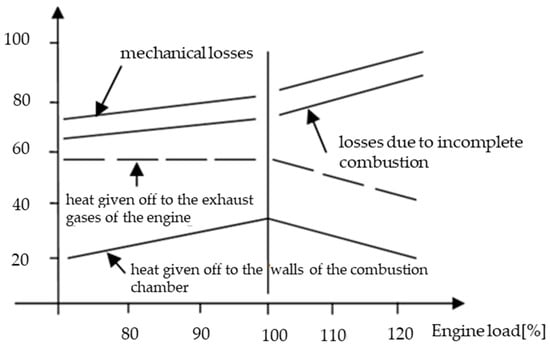
Figure 10.
Distribution of energy available in the combustion chamber of the engine by burning fuel.
Part of the flue gas energy can be used to drive the turbine or the power generator, respectively. Its size depends on the power and operating mode (speed and load) of the internal combustion engine. Its determination is done with the calculation program AMESim [50,51].
The diagram in Figure 11 can be used to calculate the mathematical model of the turbocharger.
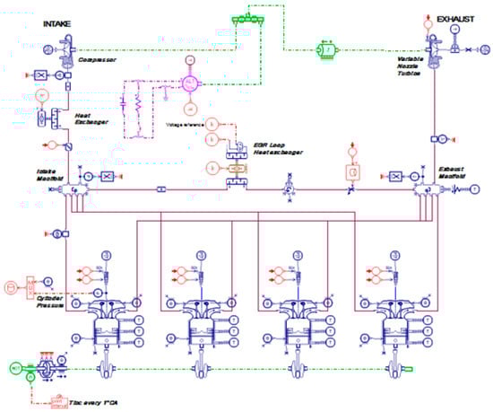
Figure 11.
Diesel 1.9 dm3 engine equipped with hybrid turbocharger simulated with AMESim software.
Since the mass of flue gases and air entering the turbine or compressor, respectively, is conserved as follows:
- The corrected and reduced speed of the turbine and the rotor are:
- The corrected flow of the gas mass expanding in the turbine blade network is:
- The power of the turbine is:
- The corrected and reduced speed of the compressor rotor are:
The equations presented above (18 and 19) determine the corrected and reduced speed of the compressor rotor, this being among the most important equations in the turbocharger system since they determine the different parametric values of the system. In this case, the unit of measurement may be “rpm”.
- The corrected flow rate of the air mass entering the compressor is:
- The air compression ratio in the compressor is:
- If the compressor is not switched on, the power generated by the alternator (Palt) is:
Under real operating conditions, the power available to the turbine shaft is distributed to the compressor and alternator. The simulations performed with the AMESim program for the case of equipping a diesel engine with a cylinder capacity of 1.9 dm3 with a hybrid turbocharger (Figure 11) allowed us to evaluate the availability of the system to generate electricity.
There are also simulations performed with the AMESim program for the case of a diesel engine without a hybrid turbocharger (naturally aspired) with a cylinder capacity of 1.9 dm3 and a hybrid turbocharger (Figure 12).
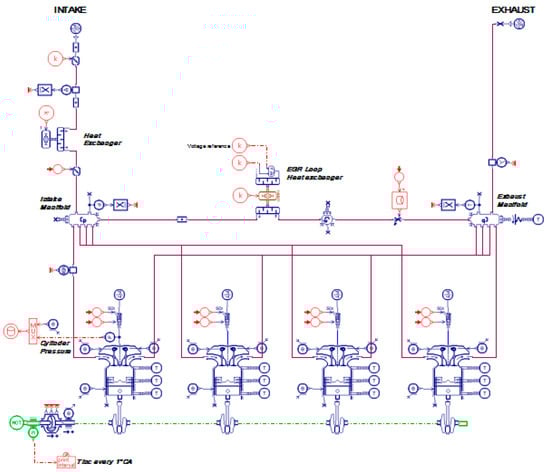
Figure 12.
Diesel 1.9 dm3 engine without a hybrid turbocharger simulated (naturally aspired) with AMESim software.
4. Results of Investigations on Virtual and Physical Models
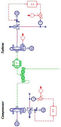
The mathematical model, developed for the study of processes in internal combustion engines, respectively, for evaluating the functional parameters of the hybrid turbocharger was used as a reference system for simulations undertaken with the AMESim program for a 1.9 dm3 diesel engine (Figure 13).
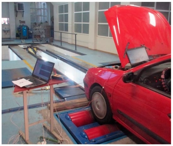
Figure 13.
Experimental research for 1.9 dm3 engine with hybrid turbocharger on Maha Dynamometer Stand.
The input data necessary to determine the characteristics of the hybrid turbocharger with the AMESim program resulted from the thermodynamic and experimental calculation undertaken on the naturally aspirated and supercharged diesel engine. The results of the virtual investigations facilitated the study of the following dependencies:
- The evolution of the speed of the turbocharger rotor shaft over time (Figure 14). The values are obtained according to the Equations (13), (14), (18) and (19). In the interval time from 0 to 2 s, it can be seen that the turbocharger rotor shaft speed increases from 0 to 135,000 rpm. After 2 s, due to the constant pressure of the exhaust gases, the turbocharger rotor shaft speed remains constant at 150,000 rpm;
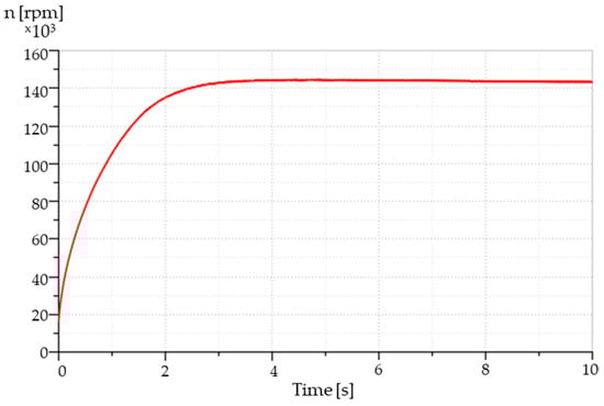 Figure 14. Turbocharger rotor speed variation simulated with AMESim software.
- 2.
- Variation of the air pressure in the vane network of the turbine and determination of the time of entry into operation of the turbocharger (Figure 15). The values are obtained according to the Equation (22);
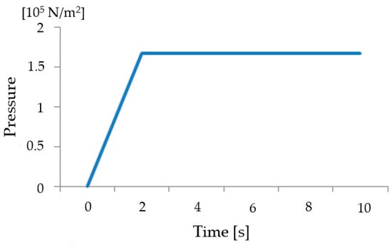 Figure 15. The compressor outlet pressure from the experimental results in relation to time.
Figure 15 illustrates the compressor outlet pressure from the experimental results over time. The range of the experimental working value is from 0 to 1.6 × 10⁵ N/m2. In the interval time from 0 to 2 s it can be seen that the compressor outlet pressure increases from 0 to 1.6 × 10⁵ N/m2. After 2 s, because of the constant pressure of the exhaust gases, the compressor outlet pressure remains constant at 1.6 × 10⁵ N/m2.
Figure 16 illustrates the compressor outlet pressure simulated with AMESim in relation to the time with the simulation value between 0 and 1.6 × 10⁵ N/m2. Due to the variable mathematical equation, in the time interval 0–10 s variable values can be seen of the compressed air pressure simulated with AMESim software.
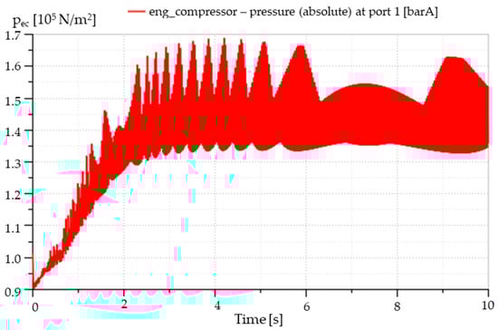
Figure 16.
Variation of compressed air pressure simulated with AMESim software.
The experiments carried out on a car equipped with a naturally aspirated 1.9 dm3 diesel engine and equipped with a hybrid turbocharger, allowed the evaluation of power and torque at the drive wheels and the energy generated by the electric generator. Figure 17 shows the experimental values for torque relative difference between hybrid turbo engine and naturally aspirated engine at 100% load. 3500 rpm represents the maximal point area of the torque relative difference between hybrid turbo engine and naturally aspirated engine at 100% load.
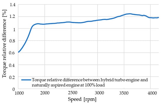
Figure 17.
Experimental values for torque relative difference between hybrid turbo engine and naturally aspired engine at 100% load.
Figure 18 presents the simulated values of torque relative difference between hybrid turbo engine and naturally aspired engine at 100% load, with AMESim software.
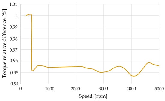
Figure 18.
Simulated torque relative difference between hybrid turbo engine and naturally aspired engine at 100% load.
Figure 19 presents the experimental values of the engine normalized power for a naturally aspired engine at 100% load, the values of the engine normalized power for a hybrid turbocharged engine at 100% load, and the variation of electrical power developed by the generator depending on the engine speed. The values are obtained according to Equation (17), including 3000 rpm as the maximal point area of the values of the engine normalized power for naturally aspired engine at 100% load and the values of the engine normalized power for hybrid turbocharged engine at 100% load.
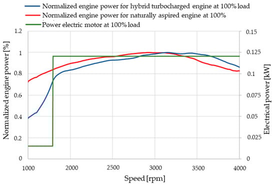
Figure 19.
Engine power and variation of power developed by the electric generator depending on the engine speed.
Figure 20 shows the voltage resulting from the AMESim simulation in relation to the time with the value of the simulation range from 0 to 23 Volts. It also illustrates the current intensity resulting from the AMESim simulation in relation to time, with the simulation value between 0 and 5 Amperes. The electrical power resulting from the AMESim simulation is also and is presented in relation to the time with the value of the simulation range from 0 to 115 Watt. The values are obtained according to the Equations (23)–(25).
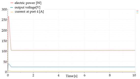
Figure 20.
The current intensity, the voltage and the power from the AMESim simulation results in relation to time.
It can be seen in Figure 7 and Figure 20 that the results from the experiments and simulations are almost similar.
The experimental diagram was built in Excel after data acquisition and the simulation diagram was built in AMESim software, therefore there are some differences, but the engine used was the same, 4 cylinder in line, 1.9 dm3 Diesel with turbocharger and 1.9 dm3 Diesel natural aspired engine.
5. Discussion
Research in the process of internal combustion engines shows that their efficiency can be increased through several technical and functional solutions, such as turbocharging. For certain engine operating modes, the available energy of the turbine can also be used to drive an electricity generator. The purpose of the paper is to highlight the possibilities and limitations of this solution. For this purpose, several investigations were carried out in the virtual environment with the AMESim program, but also experimental research on a diesel engine for cars and on a stand for testing turbochargers (Turbo Test Pro produced by CIMAT).
All compared values validated between the experimental part and the simulation part are approximately equal due to the mathematical formulas in the simulation software and also due to the minimal measurement errors.
Studies and research undertaken on physical and virtual models of the hybrid turbocharger concept adapted to internal combustion engines for automobiles have allowed the formulation of several interesting conclusions and proposals:
- The system can equip supercharged diesel engines. This requires adaptations that involve designing a well-balanced coupling system from a dynamic point of view, identifying the space available in the engine compartment for the location of the electric generator, coupling, and reducer;
- If the supercharger is tuned for the operation of the heat engine within the power range, then the electric generator can generate energy of 115–150 W in the characteristic range of the maximum motor;
- The turbine-electric generator unit can be mounted on the route of the exhaust manifolds, and it can generate electricity in the characteristic braking regimes of the car.
The use of an electric generator coupled to the compressor axle may compromises the delay of the system, but his situation was not detailed in this article, not being the subject of this study.
With the recorded and validated efficiency values, power levels of up to 1 kW could be recovered with larger electric components. Of course, implementing an inverter-based solution that runs to electric machine in motor/generator mode would be required, so as to avoid issues correlated with the increase in inertia and therefore delayed response. Nonetheless, this does not infer on the advantages of the proposed solution.
The rotational speeds of 7000 rpm were determined in a virtual simulation environment and, in this case, will be compared only on the rotational speed segment up to maximum 4000 rpm according to the experimental part. The rotational speed difference between 4000–7000 rpm is not validated in the real environment, and is only the result of the simulated calculation of the standard parameters of the engine with the AMESim software. It can be observed that the maximum points in the simulated diagrams and the real experimental diagrams correspond in the range from 0–4000 rpm. The remaining 4000–7000 rpm range in the virtual environment can be ignored in this case. It was used the same internal combustion engine 1.9 L Diesel for the simulation part as well (and was included with all specifications).
6. Conclusions
The main conclusion that may result from these experiments is that the turbocharger has a very high operating potential and can be coupled with a generator without decreasing the efficiency of the turbocharger and also the internal combustion engine. The present paper provides detailed results for the generation of electrical power at 115 W by a turbocharger shaft speed of 140,000–160,000 rpm with an electric generator shaft speed of 14,000–16,000 rpm. In the same time, this solution compress air at a range of 1.5 bar.
Figure 17, Figure 18 and Figure 20 are part of the simulation process calculated with the AMESim software, which couldn’t be limited to 5000 rpm. We compared just the interval from 0 to 5000 rpm, therefore the interval 5000–7000 rpm can be ignored on the AMESim simulation graphic results.
A weak point of this study is the loss of the mechanical power of the turbocharger due to the coupled gearbox and generator. Frictions are produced through them, and this is the main cause of the power losses. This perspective was not detailed in our research paper since the power losses of the system are very low and it is not the topic of this paper.
Regarding the possible problems for this application that can appear, we would mention the following: a reduced lifetime for the turbocharger, overheating of the generator, and the generator and gear ratio seizure.
Finally, it needs to be mentioned that none of the results presented in this study consider any electrical and mechanical losses, such as the alternator, gear ratio, or shaft transmission, which will obviously reduce the net amount of harvested energy. Future work will include investigations also on gasoline and multi-turbo systems with a comprehensive turbine/compressor.
Also, for future research improvements of the hybrid energy cogenerator turbocharger system, various constructive optimizations can be made, such as the introduction of an electromagnetic coupling on the shaft between the generator and the ratio reducer. It would have the role of disconnecting at the time of an oversaturation or overcharging the production of the electrical energy over the capacity of the generator. The electromagnetic coupling is connected to the operating parameters of the hybrid turbocharger through the main software of the vehicle.
Author Contributions
Conceptualization, R.-L.C. and A.C.; methodology, A.C.; software, R.-L.C. and R.G.B.; validation, R.-L.C., formal analysis, U.K. and R.-L.C.; investigation, R.-L.C.; data curation, R.-L.C.; writing—original draft preparation, R.-L.C. and A.C.; writing—review and editing, U.K. and R.-L.C.; visualization, R.-L.C.; supervision, A.C. All authors have read and agreed to the published version of the manuscript.
Funding
This research received no external funding.
Institutional Review Board Statement
Not applicable.
Informed Consent Statement
Not applicable.
Acknowledgments
We would like to thank for the cooperation to the company Garrett by Honeywell- turbocharger producers, Company Siemens for the AMESim software, Turbocar Serv SRL for the experimental work.
Conflicts of Interest
The authors declare no conflict of interest.
Nomenclature
| Symbol, units | Description |
| U [J] | The internal energy |
| W [J] | The transferred energy |
| Q [J] | The heat Transferred |
| S [J] | The entropy |
| T0 [J] | The atmospheric temperature |
| V [dm3] | The volume of the thermal machine |
| The total energy of the volume | |
| mc [kg] | The mass |
| μ [J] | The specific internal energy |
| The mechanical work developed as a result of burning the fuel mixture | |
| The heat release rate | |
| The enthalpy change due to crankcase leaks (hBB) | |
| pc [N/m2] | The pressure in the engine cylinder |
| α | The angle of rotation of the crankshaft |
| dmi | The mass element entering the cylinders |
| dme | The mass element coming out of the cylinders |
| hi | The specific enthalpy of the mass of flue gas which is admitted into the cylinder |
| he | The specific enthalpy of the mass of flue gas coming out of the cylinder |
| qev | Th especific heat of the exhaust gases |
| f | The fraction of heat released for fuel evaporation |
| mev [kg] | The mass of evaporated fluid |
| η | The energetic efficiency |
| Qw | The heat transferred by convection to the walls of the combustion chamber |
| αw | The convective coefficient of heat transfer (Woschwni model) |
| TC [°C] | The temperature of the gases in the cylinder |
| TW [°C] | The combustion chamber temperature |
| [rpm] | The effective turbine rotor speed |
| Te [°C] | The flue gas temperature at the turbine inlet |
| mc [kg/s] | The corrected flow rate |
| wt [rad/s] | The angular speed of the turbine rotor |
| Mt [Nm] | The torque at the turbine shaft |
| Ao | The ratio of the speed of sound in the air entering and evacuating from the compressor |
| The increase in entropy associated with irreversibility | |
| U [V] | The voltage of the current generated |
| I [A] | The current intensity generated |
| R [Ω] | The electrical resistance of the circuit |
| rpm | Revolutions per minute |
| A/R | Area over Radius |
References
- Guarda, G.; Pesyridis, A.; Sam, A.A. Preliminary Investigation of the Performance of an Engine Equipped with an Advanced Axial Turbocharger Turbine. Appl. Sci. 2020, 10, 7452. [Google Scholar] [CrossRef]
- Baietta, L.; Alshammari, M.; Pesyridis, A.; Gohil, D. Design of an Axial Turbine for Highly Downsized Internal Combustion Engines. Appl. Sci. 2020, 10, 5935. [Google Scholar] [CrossRef]
- Capata, R.; Sciubba, E. Study, Development and Prototyping of a Novel Mild Hybrid Power Train for a City Car: Design of the Turbocharger. Appl. Sci. 2021, 11, 234. [Google Scholar] [CrossRef]
- Cuturi, N.; Sciubba, E. Design of a Tandem Compressor for the Electrically-Driven Turbocharger of a Hybrid City Car. Energies 2021, 14, 2890. [Google Scholar] [CrossRef]
- Borovkov, A.; Voinov, I.; Galerkin, Y.; Kaminsky, R.; Drozdov, A.; Solovyeva, O.; Soldatova, K. Design, Plant Test and CFD Calculation of a Turbocharger for a Low-Speed Engine. Appl. Sci. 2020, 10, 8344. [Google Scholar] [CrossRef]
- Píštěk, V.; Kučera, P.; Fomin, O.; Lovska, A.; Prokop, A. Acoustic Identification of Turbocharger Impeller Mistuning—A New Tool for Low Emission Engine Development. Appl. Sci. 2020, 10, 6394. [Google Scholar] [CrossRef]
- Harvesting Exhaust Gas Energy. Available online: https://www.bmwrockville.com/harvesting-exhaust-gas-energy.htm (accessed on 15 October 2021).
- Mercedes-AMG Project One Show Car. Available online: https://www.mercedes-amg.com/en/vehicles/mercedes-amg-one.html (accessed on 15 October 2021).
- Altosole, M.; Benvenuto, G.; Campora, U.; Silvestro, F.; Terlizzi, G. Efficiency Improvement of a Natural Gas Marine Engine Using a Hybrid Turbocharger. Energies 2018, 11, 1924. [Google Scholar] [CrossRef] [Green Version]
- El-Shahat, A.; Hunter, A.; Rahman, M.; Wu, Y. Ultra-High Speed Switched Reluctance Motor-Generator for Turbocharger Applications. Energy Procedia 2019, 162, 359–368. [Google Scholar] [CrossRef]
- Dimitriou, P.; Burke, R.; Zhang, Q.; Copeland, C.; Stoffels, H. Electric Turbocharging for Energy Regeneration and Increased Efficiency at Real Driving Conditions. Appl. Sci. 2017, 7, 350. [Google Scholar] [CrossRef] [Green Version]
- Chung, J.E.; Lee, S. Measurement of Inertia of Turbocharger Rotor in a Passenger Vehicle. Trans. Korean Soc. Automot. Eng. 2016, 24, 33–38. [Google Scholar] [CrossRef]
- Naundorf, D.; Bolz, H. Turbocharger test stand with a hot gas generator for high-performance supercharging systems. MTZ Worldw. 2008, 69, 22–24. [Google Scholar] [CrossRef]
- Schutting, E.; Neureiter, A.; Fuchs, C.; Schatzberger, T.; Klell, M.; Eichlseder, H.; Kammerdiener, T. Miller- and Atkinson-Cycle on a turbocharged diesel engine. MTZ Worldw. 2007, 68, 21–23. [Google Scholar] [CrossRef]
- Khoa, N.X.; Lim, O.T. The effects of bore-stroke ratio on effective release energy, residual gas, peak pressure rise and combustion duration of a V-twin engine. J. Mech. Sci. Technol. 2020, 34, 2657–2666. [Google Scholar] [CrossRef]
- Fei, C.W.; Choy, Y.S.; Hu, D.Y.; Bai, G.C.; Tang, W.Z. Dynamic probabilistic design approach of high-pressure turbine blade-tip radial running clearance. Nonlinear Dyn. 2016, 86, 205–223. [Google Scholar] [CrossRef]
- Schlemmer-Kelling, U.; Ghetti, S.; Methfessel, P.; Marten, C. Variable Compression for Large Engine. MTZ Worldw. 2017, 78, 50–55. [Google Scholar] [CrossRef]
- Chebli, E.; Müller, M.; Leweux, J.; Gorbach, A. Development of an exhaust-gas turbocharger for HD Daimler CV engines. Auto. Tech. Rev. 2013, 2, 34–39. [Google Scholar] [CrossRef]
- Mayer, M.; Hofmann, P.; Williams, J.; Tong, D. Influence of the Engine Oil on Pre-ignitions at Highly Supercharged Direct-injection Gasoline Engines. MTZ Worldw. 2016, 77, 36–41. [Google Scholar] [CrossRef]
- Lee, Y.; Lee, S.; Choi, H.; Min, K. Analysis of Vibration on an Engine Block Caused by Combustion in a Diesel Engine. Int. J. Automot. Technol. 2019, 20, 187–195. [Google Scholar] [CrossRef]
- Hezel, B.; Ulrich, M. Cylinder head cover made of polyamide for the six-cylinder diesel engine from BMW. MTZ Worldw. 2005, 66, 6–7. [Google Scholar] [CrossRef]
- Zhou, L.; Sun, G.H.; Guo, Y.Y.; Bai, M.L. Effects of Ring Pack Friction Heat on Temperature Fields of Piston Set-Liner. Int. J. Automot. Technol. 2020, 21, 1569–1578. [Google Scholar] [CrossRef]
- Hedhli, T.; Bessrour, J. Thermomechanical behavior of the piston of an aircooled diesel engine in semi-permanent mode. Int. J. Automot. Technol. 2016, 17, 947–958. [Google Scholar] [CrossRef]
- Elbanhawy, A.; Turan, A. On Two-dimensional Predictions of Turbulent Cross-flow Induced Vibration: Forces on a Cylinder and Wake Interaction. Flow Turbul. Combust. 2010, 85, 199–224. [Google Scholar] [CrossRef]
- Liu, S.; Zhang, Y. Research on the Integrated Intercooler Intake System of Turbocharged Diesel Engine. Int. J. Automot. Technol. 2020, 21, 339–349. [Google Scholar] [CrossRef]
- Liu, Z.C.; Yuan, X.; Tian, J.; Han, Y.Q.; Yu, K.B.; Teng, P.K. Effects of Injection Timing on Transient Performance of A Regulated Two-Stage Turbocharged Diesel Engine with Turbine Bypass Valve. Int. J. Automot. Technol. 2018, 19, 783–794. [Google Scholar] [CrossRef]
- Azizi, M.A.; Brouwer, J. Stall/surge dynamics of a multi-stage air compressor in response to a load transient of a hybrid solid oxide fuel cell-gas turbine system. J. Power Sources 2017, 365, 408–418. [Google Scholar] [CrossRef] [Green Version]
- Rakopoulos, C.D.; Giakoumis, E.G. Diesel Engine Transient Operation. In Principles of Operation and Simulation Analysis; Springer: London, UK, 2009. [Google Scholar]
- Kozak, D.; Mazuro, P.; Teodorczyk, A. Numerical Simulation of Two-Stage Variable Geometry Turbine. Energies 2021, 14, 5349. [Google Scholar] [CrossRef]
- Kasprzyk, P.; Hunicz, J.; Rybak, A.; Gęca, M.S.; Mikulski, M. Excess Air Ratio Management in a Diesel Engine with Exhaust Backpressure Compensation. Sensors 2020, 20, 6701. [Google Scholar] [CrossRef]
- Zsiga, N.; Voser, C.; Onder, C.; Guzzella, L. Intake Manifold Boosting of Turbocharged Spark-Ignited Engines. Energies 2013, 6, 1746–1763. [Google Scholar] [CrossRef]
- Sturm, W.L.; Kruithof, J. Development of a heavy-duty diesel engine with two-stage turbocharging. Auto. Technol. 2001, 1, 50–53. [Google Scholar] [CrossRef]
- Piotrowski, W.; Lodefier, K.; Kubacki, S.; Elsner, W.; Dick, E. Comparison of Two Unsteady Intermittency Models for Bypass Transition Prediction on a Turbine Blade Profile. Flow Turbul. Combust 2008, 81, 369–394. [Google Scholar] [CrossRef]
- Zamboni, G.; Moggia, S.; Capobianco, M. Effects of a Dual-Loop Exhaust Gas Recirculation System and Variable Nozzle Turbine Control on the Operating Parameters of an Automotive Diesel Engine. Energies 2017, 10, 47. [Google Scholar] [CrossRef] [Green Version]
- Hu, B.; Yang, J.; Li, J.; Li, S.; Bai, H. Intelligent Control Strategy for Transient Response of a Variable Geometry Turbocharger System Based on Deep Reinforcement Learning. Processes 2019, 7, 601. [Google Scholar] [CrossRef] [Green Version]
- Yang, J.; Gao, Y.; Liu, Z.; Zhao, C.; Kang, T.; Gu, L.; Xu, B. A method for modeling and analyzing the rotor dynamics of a locomotive turbocharger. Nonlinear Dyn. 2016, 84, 287–293. [Google Scholar] [CrossRef]
- Varbanets, R.; Fomin, O.; Píštěk, V.; Klymenko, V.; Minchev, D.; Khrulev, A.; Zalozh, V.; Kučera, P. Acoustic Method for Estimation of Marine Low-Speed Engine Turbocharger Parameters. J. Mar. Sci. Eng. 2021, 9, 321. [Google Scholar] [CrossRef]
- Minasyan, A.; Bradshaw, J.; Pesyridis, A. Design and Performance Evaluation of an Axial Inflow Turbocharger Turbine. Energies 2018, 11, 278. [Google Scholar] [CrossRef] [Green Version]
- Knežević, V.; Orović, J.; Stazić, L.; Čulin, J. Fault Tree Analysis and Failure Diagnosis of Marine Diesel Engine Turbocharger System. J. Mar. Sci. Eng. 2020, 8, 1004. [Google Scholar] [CrossRef]
- Atac, O.F.; Yun, J.-E.; Noh, T. Aerodynamic Design Optimization of a Micro Radial Compressor of a Turbocharger. Energies 2018, 11, 1827. [Google Scholar] [CrossRef] [Green Version]
- Píštěk, V.; Kučera, P.; Fomin, O.; Lovska, A. Effective Mistuning Identification Method of Integrated Bladed Discs of Marine Engine Turbochargers. J. Mar. Sci. Eng. 2020, 8, 379. [Google Scholar] [CrossRef]
- Aufladung. Available online: https://docplayer.org/110428339-Aufladung-_.html (accessed on 15 October 2021).
- Ono, Y.; Shiraishi, K.; Yamashita, Y. Application of a Large Hybrid Turbocharger for Marine Electric-power Generation. Mitsubishi Heavy Ind. Tech. Rev. 2012, 49, 29–33. [Google Scholar]
- Mounaïm-Rousselle, C.; Bréquigny, P.; Dumand, C.; Houillé, S. Operating Limits for Ammonia Fuel Spark-Ignition Engine. Energies 2021, 14, 4141. [Google Scholar] [CrossRef]
- Friedrich, H.; Schier, M.; Häfele, C.; Weiler, T. Electricity from exhausts—development of thermoelectric generators for use in vehicles. ATZ Worldw. 2010, 112, 48–54. [Google Scholar] [CrossRef]
- Khajepour, A.; Fallah, S.; Goodarzi, A. Electric and Hybrid Vehicles-Technologies, Modeling and Control: A Mechatronic Approach, 1st ed.; Wiley: Hoboken, NJ, USA, 2014; ISBN 978-1-118-34151-3. [Google Scholar]
- Ghouli, Z.; Hamdi, M.; Belhaq, M. Energy harvesting from quasi-periodic vibrations using electromagnetic coupling with delay. Nonlinear Dyn. 2017, 89, 1625–1636. [Google Scholar] [CrossRef]
- Pobezhimov, V.N. Simulation of a working process in the pulsejet engine with an aerodynamic valve on the basis of the thermodynamic cycle analysis. Russ. Aeronaut. 2007, 50, 60–64. [Google Scholar] [CrossRef]
- Lim, O.T. Investigation of thermal stratification effect on n-Heptane/iso-Octane-Air mixture HCCI combustion. Int. J. Automot. Technol. 2013, 14, 843–855. [Google Scholar] [CrossRef]
- Li, P.; Mi, J. Influence of Inlet Dilution of Reactants on Premixed Combustion in a Recuperative Furnace. Flow Turbul. Combust 2011, 87, 617–638. [Google Scholar] [CrossRef]
- Qu, Z.; Nwaboh, J.; Werhahn, O.; Ebert, V. Towards a dTDLAS-Based Spectrometer for Absolute HCl Measurements in Combustion Flue Gases and a Better Evaluation of Thermal Boundary Layer Effects. Flow Turbul. Combust 2021, 106, 533–546. [Google Scholar] [CrossRef]

Publisher’s Note: MDPI stays neutral with regard to jurisdictional claims in published maps and institutional affiliations. |
© 2021 by the authors. Licensee MDPI, Basel, Switzerland. This article is an open access article distributed under the terms and conditions of the Creative Commons Attribution (CC BY) license (https://creativecommons.org/licenses/by/4.0/).