Article

Dynamic Modeling and Vibration Characteristics for a High-Speed Aero-Engine Rotor with Blade Off

1
Light Alloy Research Institute, Central South University, Changsha 410083, China
2
State Key Laboratory of High Performance Complex Manufacturing, Central South University, Changsha 410083, China
*
Author to whom correspondence should be addressed.
Appl. Sci. 2021, 11(20), 9674; https://doi.org/10.3390/app11209674
Submission received: 27 September 2021 / Revised: 15 October 2021 / Accepted: 15 October 2021 / Published: 17 October 2021
(This article belongs to the Section Acoustics and Vibrations)

Abstract

:
Blade off that occurs during operation will generate a sudden imbalance excitation and make the rotor become inertially asymmetric, which leads to large instantaneous impact load and induces more complex rotor dynamic phenomena. In order to study the transient dynamic characteristics for complex rotors suffering from blade off, a mathematical model for solving the response of the gas generator rotor in the aero-turboshaft engine is established based on the FE method and DOF condensation, in which the complex structural characteristics, transient impact load, and inertia asymmetry of the rotor are considered. The complex impeller structure is modeled by piecewise linear fitting with cylindrical beam elements and tapered beam elements. Without loss of generality, the modeling method suitable for complex rotors is verified through a general complex test rotor with modal experiments. Based on this, the responses are solved for carrying out parametric studies and an understanding of the transient dynamic characteristics of the rotor under the extreme working conditions of blade off. The results show that the blade off has a great impact effect on the time-domain waveform, frequency components, and rotor orbits. At the instantaneous stage after blade off, the complex motion is composed of synchronous motion and some lower-order natural modes excited by blade off. Although the transient responses with blade off at different rotational speeds have similar time-varying characteristics, the impact factor is sensitive to the rotating speed. Most important is that the parameter of the blade off location will not only have a significant effect on the impact factor, but also on the frequency spectrum. These dynamic characteristics as well as impact effect provide certain guidance for the fault recognition and dynamic analysis to these complex rotors suffering blade off.

1. Introduction

Blade off is a typical extreme load condition [1] that an aero-engine may suffer, which may lead to severe vibration of the aircraft and even cause the failure of some parts of the aero-engine. The fracture of a part of the blade or even the entire blade is caused by various reasons such as the fatigue failure of the blade or the mortice, bird strike, or the impact of other foreign objects. The blade off event not only can lead to large mass imbalance and blisk asymmetry but also can impose a large impact load on the rotor system, which will make the response and dynamic phenomena become more complicated. Because the blade loss may cause serious damage to the aero-engine, many authorities have made clear safety requirements [2,3] for the loss of aero-engine blade. In order to ensure the strength and integrality of the aero-engine [4], considering the testing fee and time cost, it is necessary to develop an aero-engine model to predict the complex dynamic response under the condition of blade loss before carrying out a success blade off test. Therefore, the dynamic characteristic analysis and response prediction based on analytical modeling and numerical simulation are of great importance for the aero-engine suffering blade off.
In view of the fact that the blade loss can easily cause severe vibration which may cause greater damage to the whole unit and seriously threatens flight safety, a lot of works on the blade off event have been done by scholars and demonstrated that the dynamic characteristics of the rotor suffering blade off fault are those primarily affecting aircraft safety. Obviously, the instantaneous sudden imbalance load due to blade off has a significant impact on the vibration response of the rotor system. Wang et al. [5], Kailinowski et al. [6], and Genta et al. [7], respectively, built a dynamic model for a Jeffcott rotor with blade off fault. Their research results show that the transient unbalance excitation generated by the blade off causes an instantaneous increase in rotor amplitude, and its vibration magnitude is closely related to the weight of the lost blade, the axial position, and the initial operating condition. Kalinowski et al. [6] defined the ratio of the transient response peak to the steady-state amplitude as the impact coefficient due to sudden imbalance, which is used to measure the impact effect under blade off fault. An overhung fan rotor was taken as the research object by Wang et al. [8,9] for investigating the sudden imbalance response and carrying out a fusing design suffering blade out. Li et al. [10] also investigated the transient dynamic characteristics of a cantilever single-disk rotor under sudden unbalance load. In order to analyze the response characteristics of the rotor system under sudden unbalanced excitation during the blade loss process, Sinha et al. [11,12] simplified the low-pressure rotor of a turbofan engine with a high bypass ratio to a cantilever rotor model with blades. Wei et al. [13] constructed a dynamic model of fan shaft-gear system using a Euler–Bernoulli beam element considering shear deformation. Based on this, they studied the shaft center orbits under blade loss load and vibration characteristics under windmill status. By simplifying the turbofan engine low-pressure flexible rotor into a single-disk cantilever rotor, Hong et al. [14] established a dynamic model with sudden unbalance excitation, which considered stiffness and mass distribution characteristics and load transfer characteristics. With the help of Dyrobes dynamics software, Bin et al. [15] simulated the transient response due to the last stage blade loss in a 600 MW supercritical steam turbine low-pressure rotor by applying the transient excitation force under the condition that the rotation speed was fixed at 3000 r/min and disk asymmetry was not considered. Li et al. [16] studied the dynamic characteristics of a single-disk cantilever rotor under extreme load with blade loss and carried out the safety design of support. Wang et al. [17,18,19] derived the motion equation of a typical disk-type rotor by means of the lump parameter method [17,18] and finite element method [19], respectively. Based on the model established, the internal resistance effect [17], imbalance effect [18], and bi-stable vibration characteristics [19] were studied. Based on Galerkin and Ansys, Wang et al. [20] investigated the nonlinear dynamics of the blade tip impacted, where the research object was still the cantilever fan rotor of the turbofan engine. Meanwhile, the impact effect caused by blade loss was not studied. For these complex vibration signals, Mercorelli [21,22] and Schimmack et al. [23,24] proposed a method for denoising and harmonic detection by using a non-orthogonal wavelet packet, which can isolate interference or non-coherent parts well.
In terms of rotor dynamics of turboshaft engines, Lei et al. [25] and Zhang et al. [26] established a finite element three-dimensional solid model of a turboshaft engine rotor by using ANSYS. Based on the ANSYS model, they studied the coupling vibration characteristics of a dual rotor with flexible supports. Based on the modal similarity criterion, Liao et al. [27] designed a simulated rotor test bench for the turboshaft engine gas generator rotor. Deng et al. [28] used SAMCEF to construct a dynamic model of a power turbine rotor and modified the supporting stiffness in consideration of the influence of stator. In summary, the above-mentioned research mainly focused on the natural characteristics of turboshaft engines with ANSYS. Ma et al. [29] studied the unbalanced response of a double-disk rotor system with nonlinear support. HAI et al. [30] used NASTRAN software to solve the modal parameters of the dual-rotor system and MATLAB to numerically solve the nonlinear dynamic response of the dual-rotor supported by SFD. Yang et al. [31] took the double-rotor test bench as an example and, based on the finite element method, constructed the motion equation of the rotor system by using the fixed interface modal synthesis method and carried out experimental verification. Meng et al. [32] used the transfer matrix method to calculate the critical speed, vibration mode, and unbalance response of a heavy gas turbine rotor.
It can be noted that most researchers or scholars focused their attention mainly on impact effects originated from the blade off incident but seldom paid attention to the transient response characteristics of actual rotating machinery suffering from the blade off event. In most research cases, simple rotors (Jeffcott rotors or single-disk cantilever rotors) simulated with lower degrees of freedom (DOFs) or oversimplified rotor models are adopted to explore the dynamic characteristics under extreme working conditions such as blade loss. The gas generator rotor, which is the core component of the aero-turboshaft-engine, usually runs between the second-order critical speed and the third-order critical speed and has richer dynamic characteristics than simple rotors. At present, works on the dynamic response of the turboshaft aero-engine with blade off are not reported. In addition, previous research on the dynamic modeling of aero-engine rotors mainly takes aeronautical twin-rotor engines with intermediary bearing coupling as the research object and basically simplifies the inherently complex rotor structure to a straight shaft plus rigid disk associated structure, which neglects the main structural features of the rotor and is unable to obtain dynamic characteristics consistent with reality. For the gas generator rotor used in the turboshaft engine, there is very little research on its dynamic modeling and response analysis. This is no doubt because the previous dynamic models based on constant-section beam elements or ANSYS solid elements are difficult for characterizing variable-section rotors with complex profiles, the calculation cost is very large, and the conclusions or laws obtained provide limited guidance to the actual engineering. Obviously, the vibration laws obtained by the simplified rotor in the past are no longer simply applicable to those complex turboshaft engines. Therefore, it is extremely necessary to establish a dynamic model, with a small calculation time and characterizing the complex structure of the rotor well, in order to obtain response characteristics that can guide the actual situation. Therefore, this article focuses on complex rotor dynamics modeling and transient response analysis, with the purpose of providing more valuable guidance for engine rotor dynamics design.
In order to better understand the fault features of complex aero-engines when blade loss occurs during operation, this paper aims at establishing a more reasonable dynamic model to study the dynamic response of the complicated rotor suffering blade off. Taking the typical gas generator rotor in an aero turboshaft engine (ATE) as the research object, a more reasonable rotor dynamical model is proposed based on the FE method and DOF condensation theory. The model not only considers the complex structural features and mechanical properties of the rotor, but also the coupling effects of sudden unbalance and the asymmetric inertia due to blade off. The advantage of this rotor modeling method is that the mechanical and structural features of the complicated structure can be considered and characterized with fewer DOFs, which greatly reduce the difficulty of response calculation, especially for these complex aero-engine rotors. On this basis, numerical simulations and associated experiments are both performed to verify the validity of the modeling method. Furthermore, the linear analysis and the vibration mechanism with the blade off incident in high-speed aero turboshaft engines are studied. The work can provide better theoretical and technical support for rotor modeling and fault identification of aviation turboshaft engines suffering from the blade off event.

2. Mathematical Model

The gas generator rotor is the core part for ATEs, in which the vibration intensity of the rotor directly influences the normal operation of ATEs, and even causes the whole machine to fail. Figure 1 shows the structural diagram of a gas generator rotor with 3AC1CC + 2GT layout for a typical ATE with a high power-to-weight ratio, which is composed of a front shaft head, three stage axial compressors, one stage centrifugal compressor, two stage gas turbines, and a rear shaft head. The 1-0-1 supporting form with rolling bearings is used to support the rotor. As shown in Figure 1, the gas generator rotor belongs to a typical variable cross-section structure rotor, with many conical structures, blade disks, and annular cavities, which increase the difficulty in modeling and solving. As mentioned above, the commonly used stepped cylindrical modeling method is difficult for accurately characterizing the mechanical characteristics of the rotor and predicting the vibration response easily, especially the transient response prediction under the condition of blade loss. Therefore, this paper proposes an efficient modeling method by using a combination of cylindrical elements and conical elements to simulate the complex rotor, in which Guyan DOF reduction technology is used to reduce the DOFs of system, so that a mathematical model with few DOFs but which can truly reflect the dynamic characteristics of the rotor is established.

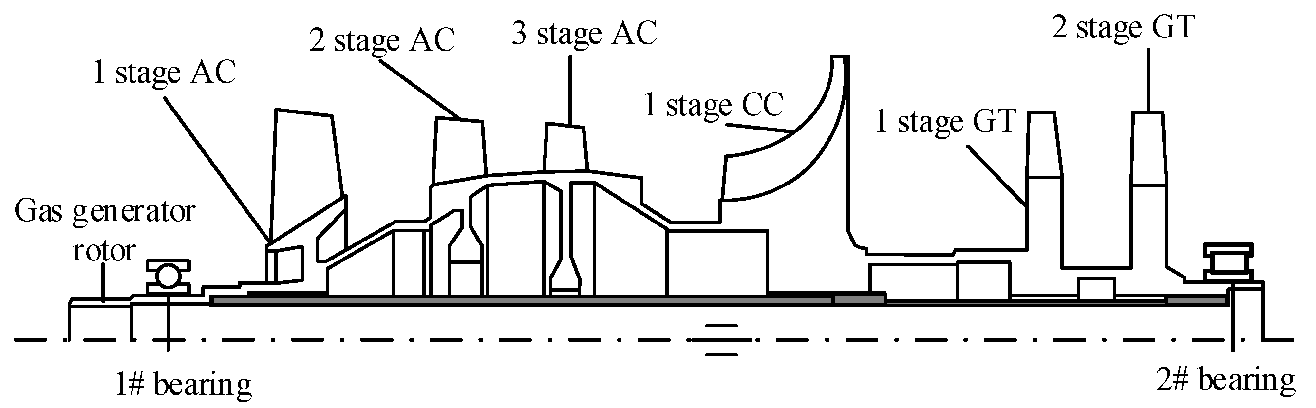
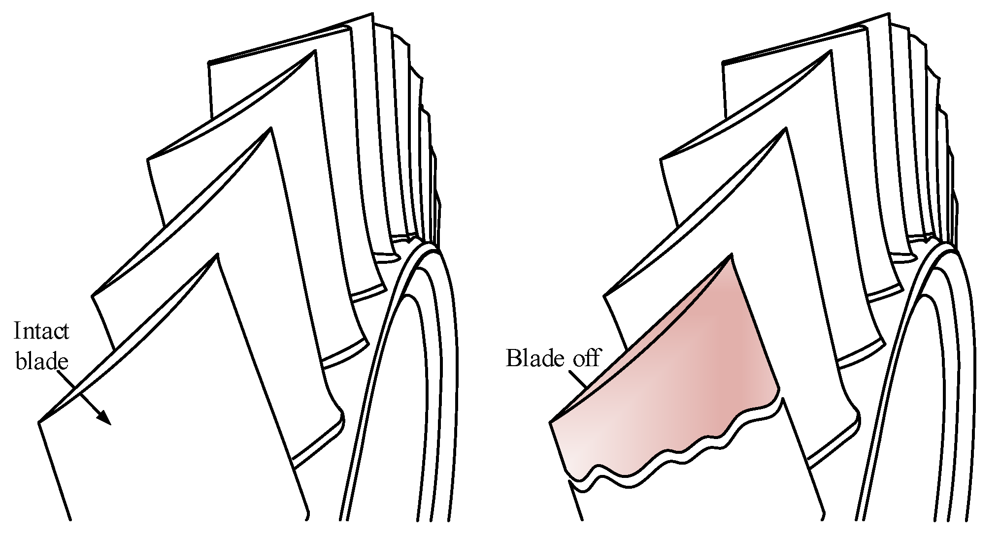
2.1. Mechanical Characteristics and Sudden Unbalance Excitation Caused by Blade Off

The gas turbine of the gas generator usually works under high-speed, -temperature, and -pressure conditions. Since the first-stage gas turbine works at the highest working temperature and is in a high-frequency vibration and high-temperature air impact environment, it is subjected to the largest thermal and impact fatigue. Therefore, the first stage gas turbine may be the earliest possible position where the blade may be broken and lost in the rotor system. Of course, blade loss events may also occur at other locations.
When the blade is lost at the moment of t1, as shown in Figure 2, the mass size of the blisk is changed suddenly, and the position of the center of mass is moved instantaneously to a new position, resulting in a larger eccentricity and impact load. Furthermore, the inertial symmetry of the blisk is also destroyed so that the rotor with blade off has significant asymmetric characteristics.

2.1.1. Sudden Unbalance Excitation

Generally, the mass center and centroid of the rotor are nearly coincident due to the highly precise machining and initial dynamic balancing technique. Hence, the initial eccentricity is assumed to be zero [3]. As the sudden load caused by the blade off is time-varying, the sudden unbalance load in x and y directions can be expressed as
{ F x = { 0 , t < t 1 m l o s s R ω 2 cos ( ω ( t t 1 ) + ϕ ) ,     t t 1 F y = { 0 , t < t 1 m l o s s R ω 2 sin ( ω ( t t 1 ) + ϕ ) ,     t t 1
where mloss is the mass of the lost blade, R is the blade centroid radius, ω denotes the rotating speed, R is the distance from the lost blade centroid to the center line of the rotating shaft, and ϕ represents the initial phase angle. When the blade is lost at the moment of t1, an instantaneous impact load will be generated. Thereafter, the steady-state unbalance force is maintained, as shown in Equation (1).

2.1.2. Inertial Asymmetry of the Blade-Disk System

As mentioned above, the blade off event will make the disk become asymmetric in structure. The motion equation of the damaged blade-disk system can be deduced by
d d t ( T d q ˙ d ) ( T d q d ) = 0
where q = [xd, yd, θxd, θyd]T. The subscript d is used to identify the disk parameters. xd and yd are the translational displacements in the x and y directions, respectively. θxd and θyd are the rotational displacements around the x and y directions, respectively. When the blade loss occurs, the polar moment of inertia of the blisk system is reduced to
J l o s s = J p m l o s s R 2
where Jp is the polar moment of the inertia of the intact blisk, and mloss denotes the lost mass of the blade.
The diameter moments of inertia around the X-axis and Y-axis change to J x = J p / 2 m l o s s R 2 and J y = J p / 2 , respectively. Then, the kinetic energy of the damaged blade-disk system can be expressed in the form
T d = 1 2 m b ( x ˙ d 2 + y ˙ d 2 ) + 1 2 J x ( θ ˙ x d cos ω t + θ ˙ y d sin ω t ) 2 + 1 2 J y ( θ ˙ x d sin ω t θ ˙ y d cos ω t ) 2 + 1 2 J l o s s ( ω 2 + ω ( θ ˙ x d θ y d θ ˙ y d θ x d ) )
where mb is the mass of the blisk after the blade is lost. The average diameter moment of inertia (Jm) and the asymmetrical increment of inertia ( Δ J y x ) of the blisk system can be expressed as
J m = 1 2 ( J x + J y ) = 1 2 J p Δ J
Δ J = 1 2 ( J y J x ) = 1 2 m l o s s R 2
Equation (6) indicates the asymmetry between Jy and Jx. By substituting Equation (4) into Equation (2), the motion equation of the damaged blade-disk system can be derived as
( M d s + M d v ( t ) ) q ¨ + ( G d s + G d v ( t ) ) q ˙ = 0
where Mds and Gds represent the constant components of mass and gyroscopic matrices, respectively, and Mdv(t) and Gdv(t) denote the corresponding time-varying components of mass and gyroscopic matrices, respectively, of which the time-varying period T = π/ω. Those matrices are expressed as follows.
M d s = [ m b 0 0 0 0 m b 0 0 0 0 J m 0 0 0 0 J m ]
M d v ( t ) = Δ J [ 0 0 0 0 0 0 0 0 0 0 cos 2 ω t sin 2 ω t 0 0 sin 2 ω t cos 2 ω t ]
G d s = [ 0 0 0 0 0 0 0 0 0 0 0 J l o s s ω 0 0 J l o s s ω 0 ]
G d v ( t ) = 2 ω Δ J [ 0 0 0 0 0 0 0 0 0 0 sin 2 ω t cos 2 ω t 0 0 cos 2 ω t sin 2 ω t ]

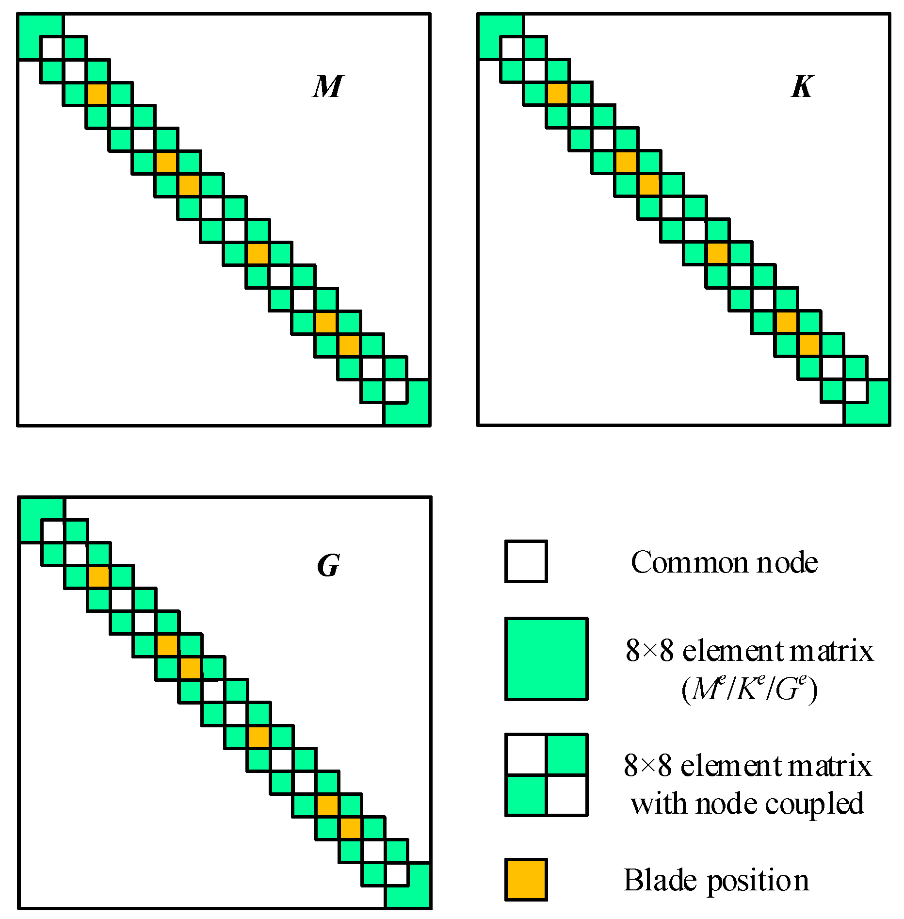
2.2. The Motion Governing Equation of Gas Turbine Rotor with Blade off

Considering the complexity of the rotor structure investigated, the varying cross-section structures are simulated with a series of cylindrical and conical beam elements; after that, the system’s DOFs are reduced by Guyan theory. On the basis of this, a typical high-speed gas generator rotor with complex structures shown in Figure 1 is discretized based on the FE method and Guyan reduction technology, as shown in Figure 3a. To facilitate the understanding of the modeling process, the final equivalent mechanical model is presented in Figure 3b, in which the rotatory inertia, shear effect, and gyroscopic moment are considered. Each node of the main element has four DOFs (two translational and two rotational DOFs). In view of the fact that the left and right bearings are rolling bearings, the supports are modeled as linear spring-damping models, where the supporting stiffness and damping are 2 × 10⁴ N/mm and 0.5 N·s/mm, respectively. The blades at each stage are regarded as lumped mass [33] applied to the corresponding nodes, such as nodes 4, 7, 8, and so on.
For a cylindrical or conical beam element shown in Figure 3a, the (8 × 8) inertia or stiffness matrixes can be expressed in the general form
A e = [ a 11 0 a 22 s y m 0 a 32 a 33 a 41 0 0 a 44 a 51 0 0 a 54 a 55 0 a 62 a 63 0 0 a 66 0 a 72 a 73 0 0 a 76 a 77 a 81 0 0 a 84 a 85 0 0 a 88 ]
Corresponding to Equation (12), the (4 × 4) stiffness and inertia matrixes in XOZ plane are well documented in any book [34] or reference [35,36] about rotor dynamics. Once the 4-by-4 matrix is known, the 8-by-8 matrix (Equation (12)) can be obtained according to the relationships between the XOZ and YOZ planes [37]. The gyroscopic matrix can be written as
G e = [ 0 G 21 0 skew   s y m G 31 0 0 0 G 42 G 43 0 0 G 52 G 53 0 0 G 61 0 0 G 64 G 65 0 G 71 0 0 G 74 G 75 0 0 0 G 82 G 83 0 0 G 86 G 87 0 ] G 21 = ρ I 15 L ( 1 + Φ ) 2 ( 36 ) ,   G 31 = ρ I 15 L ( 1 + Φ ) 2 ( 3 15 Φ ) L , G 43 = ρ I 15 L ( 1 + Φ ) 2 ( 4 + 5 Φ + 10 Φ 2 ) L 2 ,   G 83 = ρ I 15 L ( 1 + Φ ) 2 ( 1 5 Φ + 5 Φ 2 ) L 2 , G 61 = G 21 , G 71 = G 31 ,   G 42 = G 31 , G 52 = G 21 , G 82 = G 31 , G 53 = G 31 , G 64 = G 31 ,   G 74 = G 83 , G 65 = G 21 , G 75 = G 31 , G 86 = G 31 ,   G 87 = G 43 .
where ρ, I, L, E, and G represent the density, area moment, length, elastic modulus, and shear modulus, respectively. Φ = 12EI/(0.886AGL2).
Once all of the sub-element beam equations in each main element are deduced into the 8 × 8 main matrix on the basis of Guyan theory, the mass matrix (Mr), the stiffness matrix (Kr), and the gyroscopic matrix (Gr) for the whole rotor system can be obtained by assembling all of the main element matrices, and the assembly procedure is depicted in Figure 4. Then, based on the rotor dynamics theory, the dynamic governing equation with 72 DOFs describing the rotor motion induced by blade off is deduced as
( M + M b ( t ) ) q ¨ + ( C + G + G b ( t ) ) q ˙ + K q = F ( t )
where q = [x1, y1, θx1, θy1, …, x18, y18, θx18, θy18]T is the generalized displacement vector. M and G are the constant components of the global mass matrix and gyroscopic matrix, respectively, while Mb(t) and Gb(t) are the corresponding time-varying components due to blade-loss, respectively. K denotes the stiffness matrix. F(t) is the sudden unbalance excitation when blade off occurs in a blade-disk. The structural damping matrix, C, is obtained by using the Rayleigh damping formulation [38], which can be written as
C = α M + β K
α = 4 π ω n 1 ω n 2 ( ξ 1 ω n 2 ξ 2 ω n 1 ) ( ω n 2 2 ω n 1 2 ) ,   β = ξ 2 ω n 2 ξ 1 ω n 1 π ( ω n 2 2 ω n 1 2 )
where ω n 1 and ω n 2 are the first- and second-order undamped natural frequencies calculated; ξ1 and ξ2 represent the first two-order modal damping ratios, which are set to 0.02.
The obtained sparse matrices (M, K, G) can improve the calculation speed for vibration responses. However, the obtained mode shapes are not smooth enough because the continuous rotor is discrete in a finite number of elements. Similar to other modeling methods, such as the lumped mass method, finite element method with beam theory, etc., [3,17,18], this is an inevitable defect, but it will not affect the calculation accuracy of natural frequency, mode, and response.

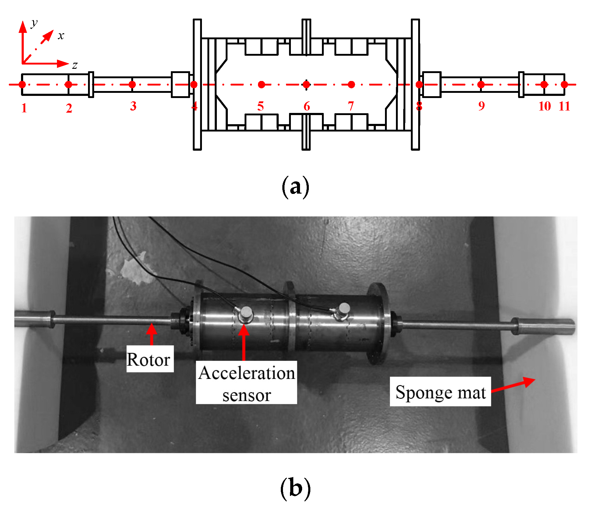
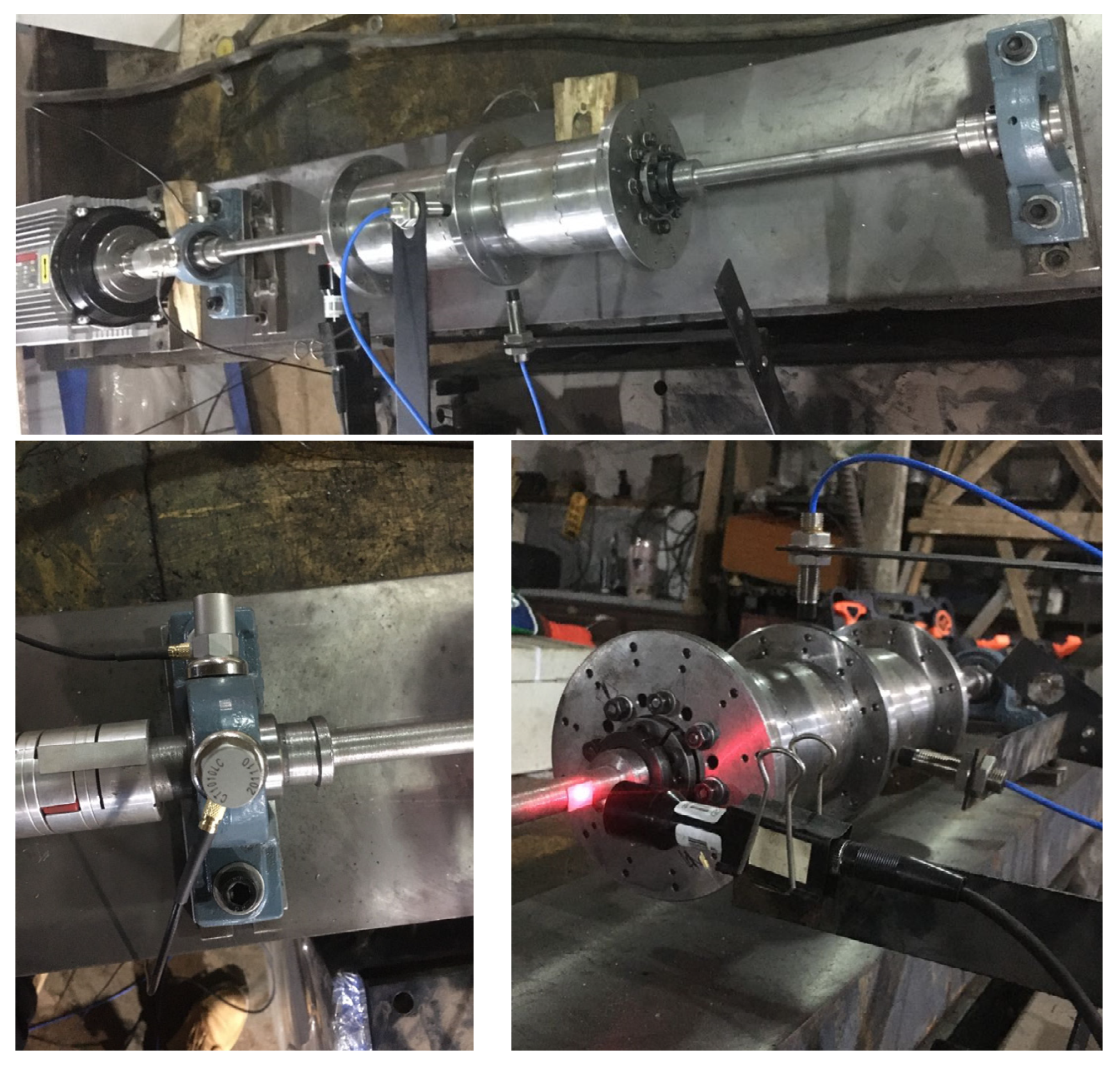
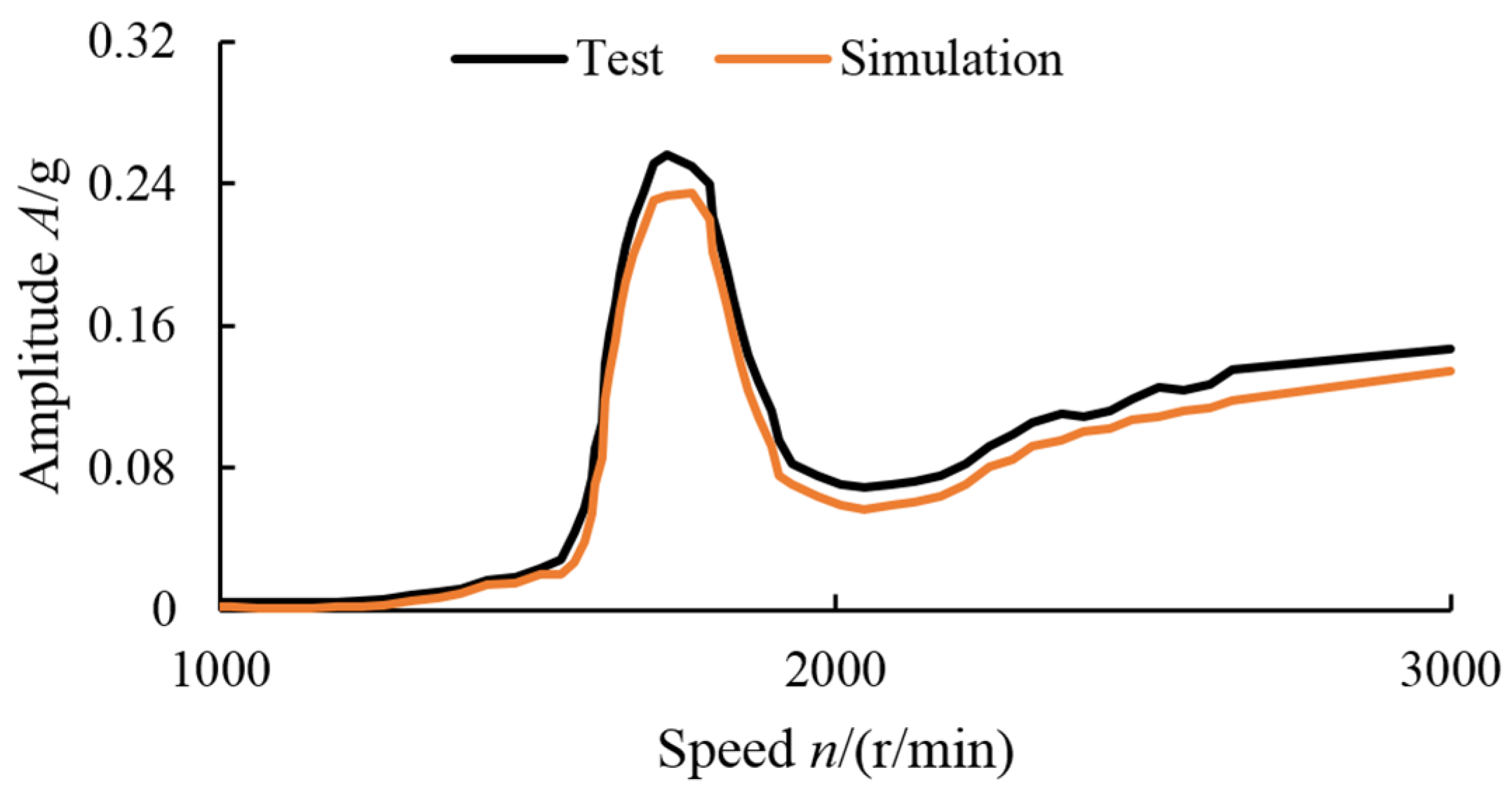
3. Modeling Method Validation through a Test Rotor

In order to verify the modeling method proposed in this paper, a rotor with both conical and cylindrical structures was designed, as shown in Figure 5. The dynamic model of the test rotor is established with 10 main elements, as shown in Figure 5a. The frequency response function of the test rotor is obtained by hammering method under approximately free boundary conditions (see Figure 5b). A comparison between the tested and the calculated results for the first three natural frequencies is shown in Table 1. The first three modes are cylindrical mode, conical mode, and bending mode, respectively. It can be seen from Table 1 that the calculated results agree well with those of the tested, and the maximum relative error is within 3.2%, which shows that the modeling method is correct and reliable.
To further verify the effectiveness of the proposed modeling method for complex rotors, response simulation and corresponding vibration tests were carried out. As shown in Figure 6, the test rotor is driven by a three-phase AC motor controlled by a frequency converter, with rolling bearings at both ends (Model: UCP205). The vibration signal of the bearing seat was collected by a piezoelectric acceleration sensor (sensitivity: 98.1 mV/g), and the rotor rotation pulse signal was collected by the combination of a non-contact photoelectric sensor and reflector. In order to simulate the unbalance force caused by blade loss, a screw was added to the hole corresponding to node 4. Within the speed range of 1000–3000 r/min, the vibration response was measured at an interval of 100 r/min, and the amplitude of the steady-state response at every speed was taken to obtain the amplitude-frequency response curve, which is compared with the simulation result, as shown in Figure 7. It can be seen from the comparison of the response curves that the simulation and test results show the same trend of vibration with rotation speed, and the difference between them is small. The amplitude difference between simulation and test results is because the test rotor has a certain residual imbalance caused by machining and assembling in addition to the unbalance screw applied, which is only applied on the simulated model.

4. Numerical Results and Discussion

The motion Equation (14) of the gas turbine rotor system suffering from a blade off incident is solved numerically by using the Newmark-beta integral algorithm, which is an efficient calculation algorithm and meets the research objective. A time step size of 1e-5 s is specified for the numerical integration. On the basis of this, the transient response of 1.5 s is solved to show the time-frequency characteristics and the impact effect when blade off occurs at t = 0.05 s. The corresponding parameters for blade off are listed in Table 2. Taking the rotational speed and blade off location as control parameters in the simulation, the vibration time-domain waveform, spectrum, and rotor orbit are adopted to investigate the transient response and blade off mechanism of the high-speed gas turbine rotor system with complicated structure characteristics. As discussed below, the obtained results reveal the transient dynamic response and evolution of the rotor system in the case of blade off.

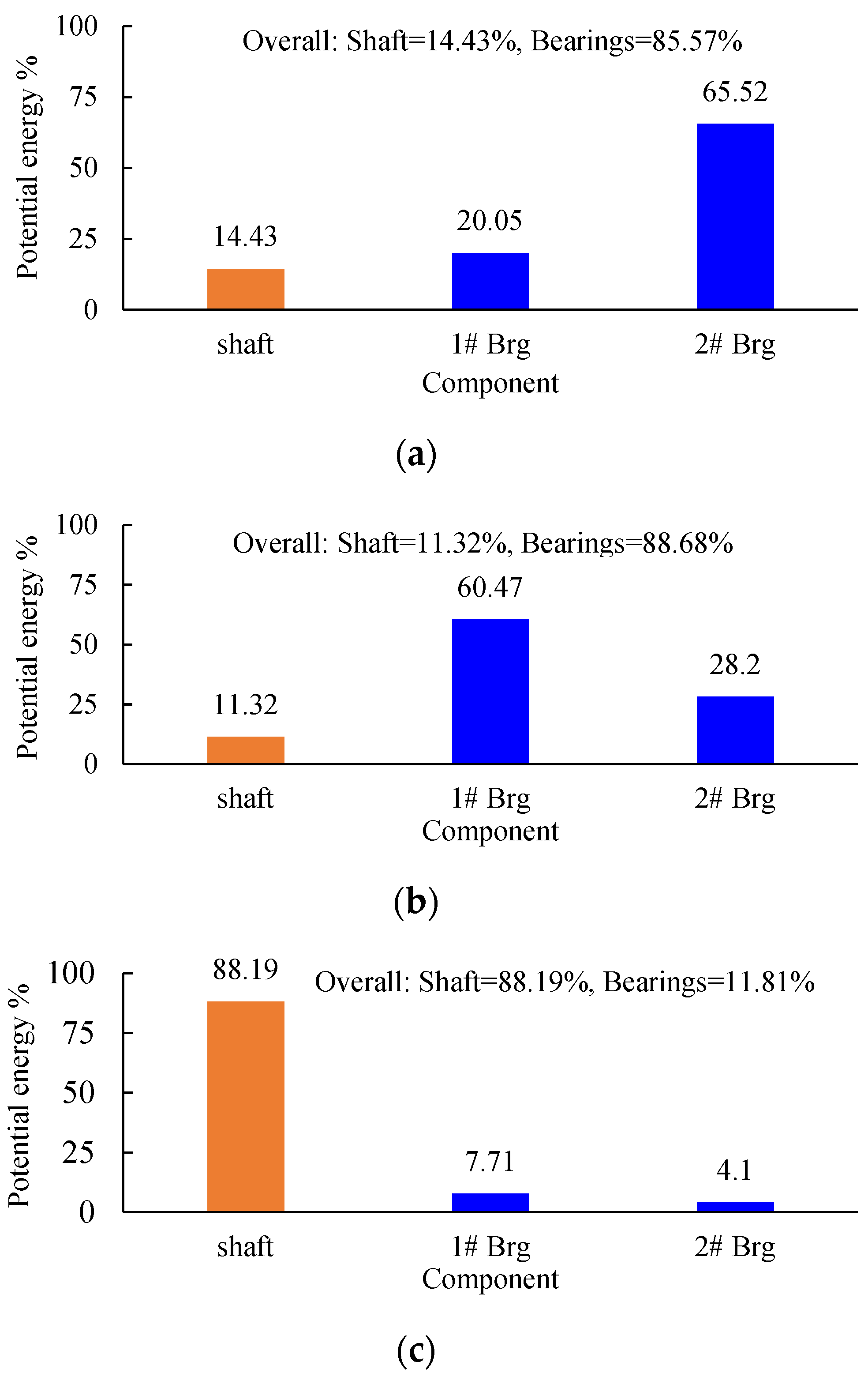
4.1. Critical Speeds and Mode Shapes

The critical speeds and corresponding mode shapes are helpful for giving insight into the dynamic characteristics of the gas turbine rotor with blade off. The first step is to conduct critical speed analysis. The first three-order critical speeds are calculated, respectively, to be 10,782 r/min, 22,856 r/min, and 73,527 r/min, which shows that there are two critical speeds below the maximum speed. Figure 8 represents the mode shapes corresponding to the first three-order critical speeds, which are respectively the translational mode, the pitching mode, and the first bending mode, where the first two can be regarded as rigid modes due to most of the strain energy being concentrated on the bearings (see Figure 9a,b). According to the rotor dynamics theory, the first two rigid body modes are most likely to be excited when the rotor is disturbed by internal or external interference. Obviously, the modal analysis is helpful for the understanding of the transient responses which will be discussed later.

4.2. Evolution of Transient Dynamic Response of Blade off

The transient response induced by blade off is complicated, as the sudden unbalance not only can produce a large impact force but also a constant unbalance force. In order to effectively reveal the time-frequency characteristics of the transient response for the gas generator rotor suffering blade off, on the basis of considering the actual operating conditions and the fact that the first stage gas turbine is the earliest possible position where the blade is most likely to be lost during operation, the transient response in 1.5 s is calculated at the highest speed of the engine with the blade off occurring at the first stage gas turbine at the moment of 0.05 s.

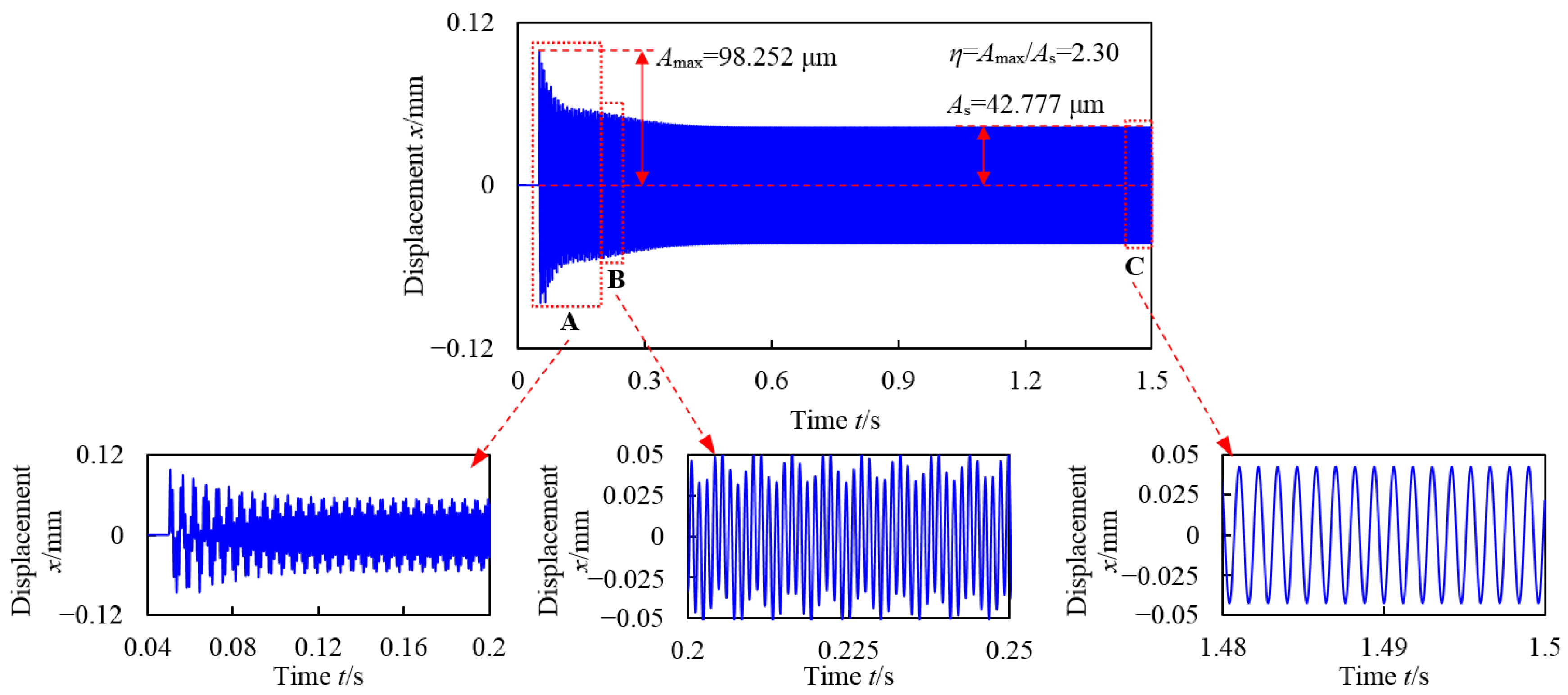
4.2.1. Time-Domain Response Characteristics

The time-domain responses at different nodes are respectively shown in Figure 10, Figure 11 and Figure 12, and corresponding motion orbits are depicted in Figure 13. It can be seen that when the sudden unbalance is applied on the rotor, i.e., the blade off occurs at the moment t = 0.05 s, the amplitude of the transient response increases suddenly and quickly reaches a peak point, then oscillates downward within a certain time range, and finally decays to a stable value after several revolutions due to the damping existing in the system. Obviously, the system response finally presents a typical synchronous vibration state due to the large steady-state unbalance excitation remaining. Figure 10, Figure 11 and Figure 12 also show that the tendency of the vibration amplitude at different positions over time is basically the same. The above-mentioned vibration amplitude changing process with time indicates that the sudden imbalance has a significant impact on the rotor system.

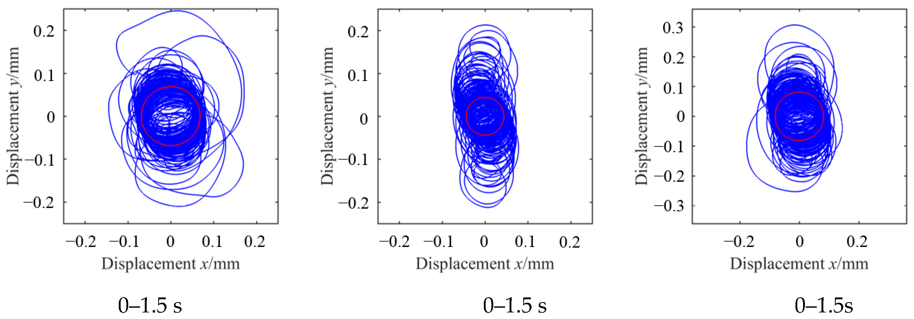
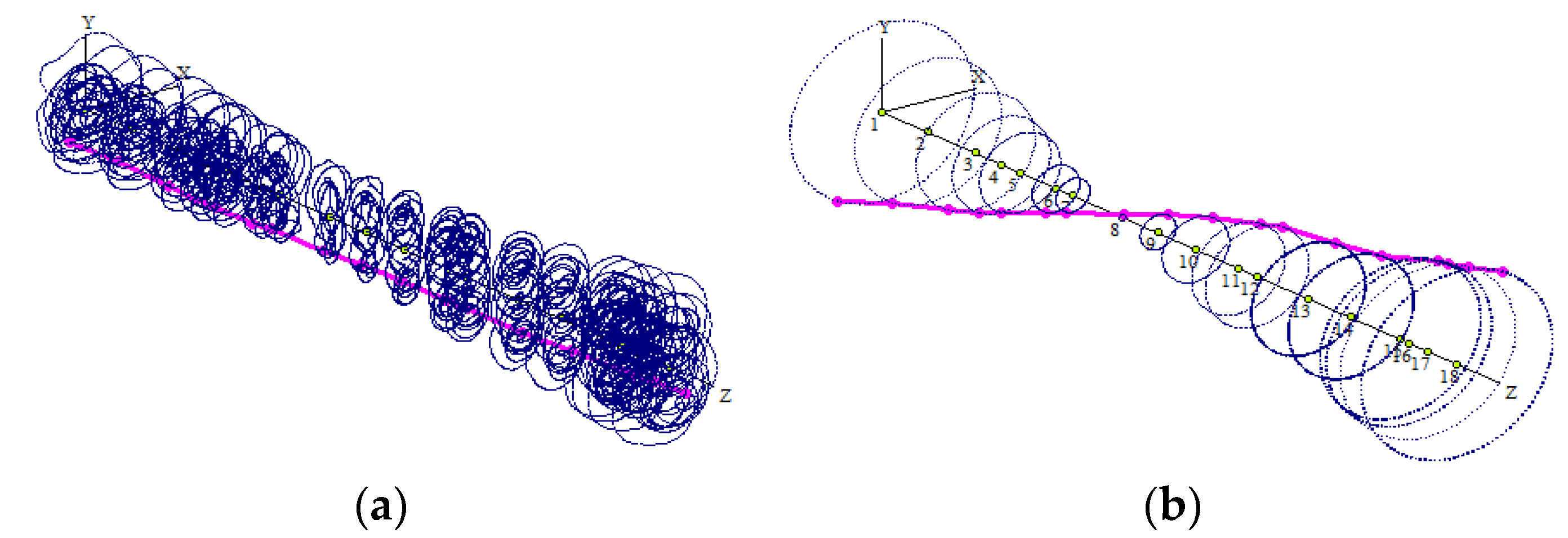
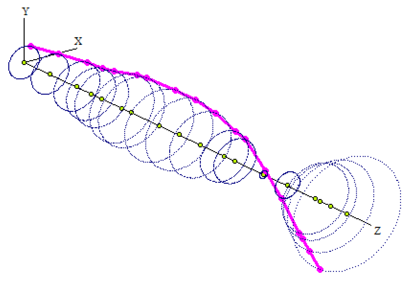
4.2.2. Transient Orbit Characteristics

In addition to the significant impact of blade off on the vibration displacement, it also has a significant influence on the trajectory and frequency components in the response. By comparing the orbits at different times, as shown in Figure 13, it can be seen that at the moment of the blade loss, the orbit is very turbulent, with a large initial vibration amplitude, but gradually becomes a regular circle, with the vibration waveform of a simple sine wave. In addition, the motion orbits at different positions are very similar, as shown in Figure 13a–c, while the maximum response displacement and steady-state amplitude of the bearings at both ends are greater than those at the center of gravity. The reason for this is due to the dynamic characteristics of the gas generator rotor operating at 50,000 r/min. The excitation at node 14 cannot effectively excite the third-order mode (see Figure 8c), and node 11 in the excited second-order mode is much closer to the node point (see Figure 8b), so the vibration at the center of gravity is smaller than those at other positions.

4.2.3. Frequency-Domain Response Characteristics

In order to learn about the instantaneous response frequency component and the steady-state response frequency components, the time-domain responses within 0.05–0.12 s and 1–1.5 s are respectively taken by FFT to obtain the corresponding frequency-domain responses, as shown in Figure 14. The results show that some natural vibration modes of the rotor system are excited by the sudden imbalance induced by the blade off occurring at the first stage gas turbine. The first natural frequency (fn1, the backward and forward frequencies are basically the same due to the weak gyroscopic effect on the first natural mode), the second backward frequency (fn1−), and the forward frequency (fn2+) exist in the spectrums of both bearings, while only the first natural frequency exists in the spectrum of Node 11, which is because the second natural mode is difficult to excite by the excitation near the C.G. position as mentioned above. Importantly, the high-order natural frequency components decay faster than the lower-order, while the rotational frequency (fr) is always present, and its vibration amplitude remains unchanged. The reason for this is self-explanatory.

4.2.4. Impact Effect Due to Sudden Unbalance

In order to quantitatively evaluate the impact effect, the impact factor [6] is defined as η = Amax/As, where Amax and As are respectively the transient peak amplitude and corresponding steady-state amplitude. By extracting the instantaneous displacement peak and steady-state vibration amplitude in the time series of vibration response, the impact factors at different locations are obtained, as shown in Figure 15. By comparing the transient peaks, steady-state amplitudes, and the impact factors at different locations, it shows that the vibration response and impact factors at both ends are greater than those at C.G. (node 11), while the values are similar, i.e., for this kind of rigid rotor located in the bearing span, the impact effects on different axial positions are similar with the range from 2.3 to 2.8, which also shows that the impact effect is obvious. Although the difference of the impact effect at different locations is small, the maximum transient responses of both bearings are much higher than that at the C.G., about 1/2 of the bearings. The reason for this is due to the special vibration characteristics when the rotor is subjected to blade off on the first stage gas turbine at a rotational speed of 50,000 r/min. The vibration modes shown in Figure 16 and the critical speed mode shapes shown in Figure 8 are sufficient to explain the reason for these dynamic phenomena appearing, i.e., the vibration amplitude of the bearings at both ends in the pitching vibration mode excited is greater than those near the C.G. of the entire system.
From the above analyses, it can be seen that the impact has time-dependent characteristics. The large unbalance force as well as the instantaneous impact force caused by the loss of blade are the fundamental reasons for the sharp increase in vibration response. The above-mentioned time-frequency characteristics can provide a better theoretical basis for the fault diagnosis to this type of rotor suffering from blade off.

4.3. Parametric Analysis

4.3.1. Influence of Rotational Speed

As we all know, the rotational speed has a significant influence on the dynamic characteristics. In view of this, this section studies the influence of rotating speed. Figure 17 represents the vibration response in time domain, and Figure 18 shows the response in the frequency domain at different nodes when the rotor operates at 30,000 r/min, which is the lower limit of the working speed. The corresponding impact factors at the maximum and minimum operating speeds are both shown in Figure 19. By comparing the time-domain and frequency-domain responses at different speeds, i.e., comparing Figure 5 with Figure 10 and comparing Figure 14 with Figure 18, it can be seen that the time-domain and frequency-domain responses at different speeds have similar characteristics (the vibration amplitude increases suddenly when blade off event occurs and then decays to a stable value; in addition, the first natural frequency and the second forward and backward processional frequencies can be excited by the impact load, while the amplitude with a higher-order frequency has a faster attenuation rate), while for all the nodes, the impact factor of 50,000 r/min is greater than that of 30,000 r/min (see Figure 19), which indicates that the higher the speed, the more susceptible the rotor motion state is to the impact load, i.e., within the working speed range, the rotor system operating at higher speeds is more sensitive to impact load, which is consistent with the results reported in [9,14].

4.3.2. Influence of Blade off Location

Considering that the first-stage axial compressor (1AC) is the most susceptible to foreign objects, it is also one of the most likely locations for blade loss in the turboshaft engine. This section studies the influence of the blade off location on the dynamic characteristics.
Figure 20 shows the comparison of impact factors when blade off occurs at 1AC and the first-stage gas turbine (1GT). It shows that the blade off location has a significant effect on the impact factor. When the blade off location is changed from 1GT to 1AC, the impact factor at 1# support is increased from 2.8 to 6.84. In contrast, the impact factor at 2# support and the center of gravity position does not increase but decrease, although the decrease is small. This is because the sudden unbalance excitation at different locations has a distinct sensitivity to each mode of the rotor operating at a certain speed. The details are as follows. It can be seen from the mode shapes shown in Figure 8 that the first three-order critical modes can be effectively excited by the excitation at 1AC, while the excitation at 1GT can only excite the first two modes. In addition, the effects of the sudden unbalance excitation at different locations on each mode are inconsistent. Namely, the first-order critical mode (Figure 8a) is easier to be excited by the excitation at 1GT than that at 1AC, while the second- and third-order critical modes are just the opposite, especially for the third-order mode (Figure 8c), which can hardly be excited by the excitation at 1GT since the vibration node point is near 1GT. The above reasons will cause the transient response excited by the blade loss of 1AC to be greater than that caused by the loss of the 1GT blade. From the steady-state vibration mode (Figure 21) caused by the large unbalance excitation at 1AC, it can be seen that the steady-state amplitude of 1# support is smaller than that of the C.G. position and 2# support. As a result, when the blade loss occurs at 1AC, the large transient response peak and the smaller steady-state vibration amplitude at 1# support cause a large impact factor. Apparently, the 1# bearing and its supporting structure are most vulnerable to damage, such that some safety design methods need to be adopted.
The frequency-domain responses at the instantaneous stage (0.05–0.12 s) when blade off occurs at two different locations (1AC and 1GT) are shown in Figure 22. Obviously, there are big differences in the frequency components between these two cases. It can be seen from Figure 22 that the sudden unbalance excitation at 1AC can excite the first three-order natural modes simultaneously (fn1, fn2−, fn2+, fn3−, fn3+), while the excitation at 1GT can only excite the first two modes (fn1, fn2−, fn2+). Furthermore, the amplitudes of the second-order modes (fn2−, fn2+) excited by the sudden unbalance excitation at 1AC are larger than those excited by 1GT. For example, when the blade off event changes from 1GT to 1AC, the amplitude of the second backward precession frequency component increases from 5.27 μm to 12.3 μm. Another significant vibration difference between these two cases of blade off can also be observed in Figure 22a,c, i.e., in all the natural modes excited by sudden unbalance excitation, when the blade off occurs at 1GT, the first natural frequency component has the largest amplitude; however, the amplitude of the second forward natural frequency component is the largest when the blade off occurs at 1AC.
In a word, the above analysis shows that the parameter of the blade off location will not only have a significant effect on the impact factor, but also on the frequency spectrum characteristics at each node of the rotor. The above-mentioned frequency spectrum difference and impact factor distribution characteristics can provide a better theoretical basis for the fault recognition and safety design for this type of rotor suffering from blade off. What needs to be pointed out is that some noise signals are generally mixed in the vibration signals obtained in the actual test. In order to isolate these low-frequency noises, a method using non-orthogonal wavelet packet denoising and harmonic detection proposed in [21,22,23,24] is recommended to eliminate these disturbances, as it can isolate interference or non-coherent parts well.

4.4. Comparison of Simulation and Test Data

In order to verify the reliability of the rotor model established, the unbalance response obtained by simulation is compared with the measured data. According to the data of the residual unbalance displayed by the dynamic balancing machine, unbalances of 35 g·mm and 25 g·mm are applied to node 7 and node 15 of the dynamic model established, respectively. The amplitude-frequency response curves corresponding to node 13 obtained by the simulation and measurement are shown in Figure 23. The comparison analysis shows that the simulation and test results are basically consistent, which indicates that the model has enough accuracy. Because node 13 is close to the node position of the second-order mode shape (see Figure 8b), there is no second-order resonance peak in the unbalance response versus speed curves. The response error between simulation and measured data is mainly caused by machining and assembly. Overall, the dynamic model established in the study is effective and suitable.

5. Conclusions

This paper focuses on the dynamic modeling and transient response characteristics of a complicated gas generator rotor in a turboshaft engine with blade off. It is proposed that the finite element method with cylindrical and conical elements combined with the reduction of system degrees of freedom is used to establish the dynamic model of the complex rotors, in which the complex structural characteristics, sudden unbalance excitation, and inertia asymmetry can be considered. Then, the validity of the modeling method proposed for complicated rotors is verified through experiments with a general complex rotor. On the basis of the established dynamical model used for blade off transient response analysis, the vibration mechanism of blade off for the actual rotating machinery is studied by time-frequency analysis. Furthermore, parametric studies including the rotational speed and blade off location are carried out in detail. The main conclusions are as follows:
(1)
The validity of the rotor modeling method is verified by a test. The proposed dynamic model can reflect the dynamic characteristics of the complicated rotor well. It is suitable for vibration analysis because the complex rotor structure is characterized with fewer degrees of freedom. Based on the dynamic model established, the natural characteristics and transient response evolution, including the time-domain, frequency-domain, and orbit, of a high-speed gas generator rotor with blade off are revealed.
(2)
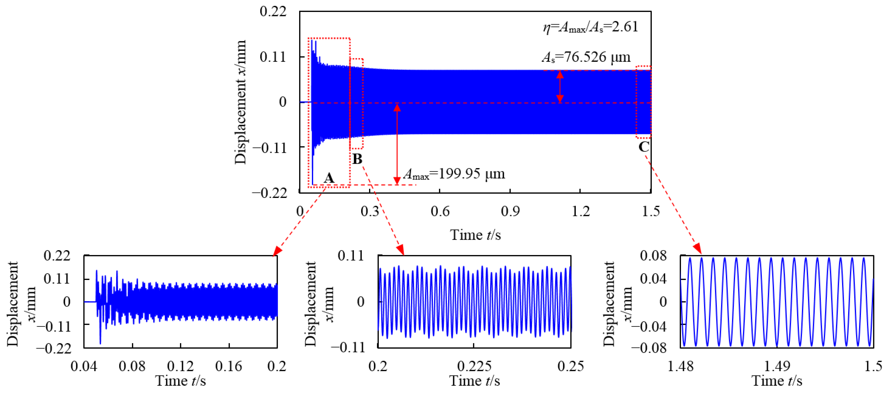
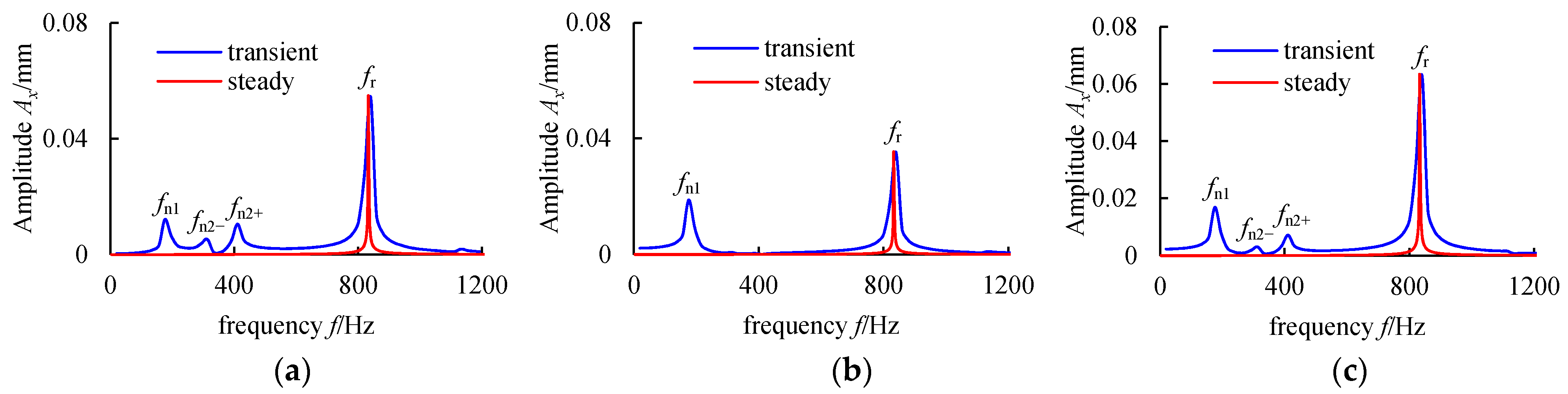
The impact effect due to blade off has time-dependent and location-dependent characteristics. When the blade off occurs, the amplitude of transient response increases suddenly and reaches to a peak point soon and then oscillates downward to a stable value with several revolutions. The instantaneous impact force due to blade off is the fundamental reason for the sharp increase in vibration response, and the generated large unbalance after blade off and system damping are the reason for the finally stable amplitude reached. The blade off excites some lower-order natural modes, such that the transient response contains some lower natural frequency components.
(3)
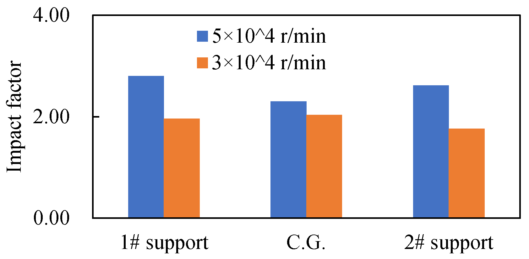
The responses of the rotor with blade off occurring at different rotational speeds have similar characteristics, while the rotational speed has a significant influence on the impact factor, i.e., the higher the speed, the greater the impact factor.
(4)
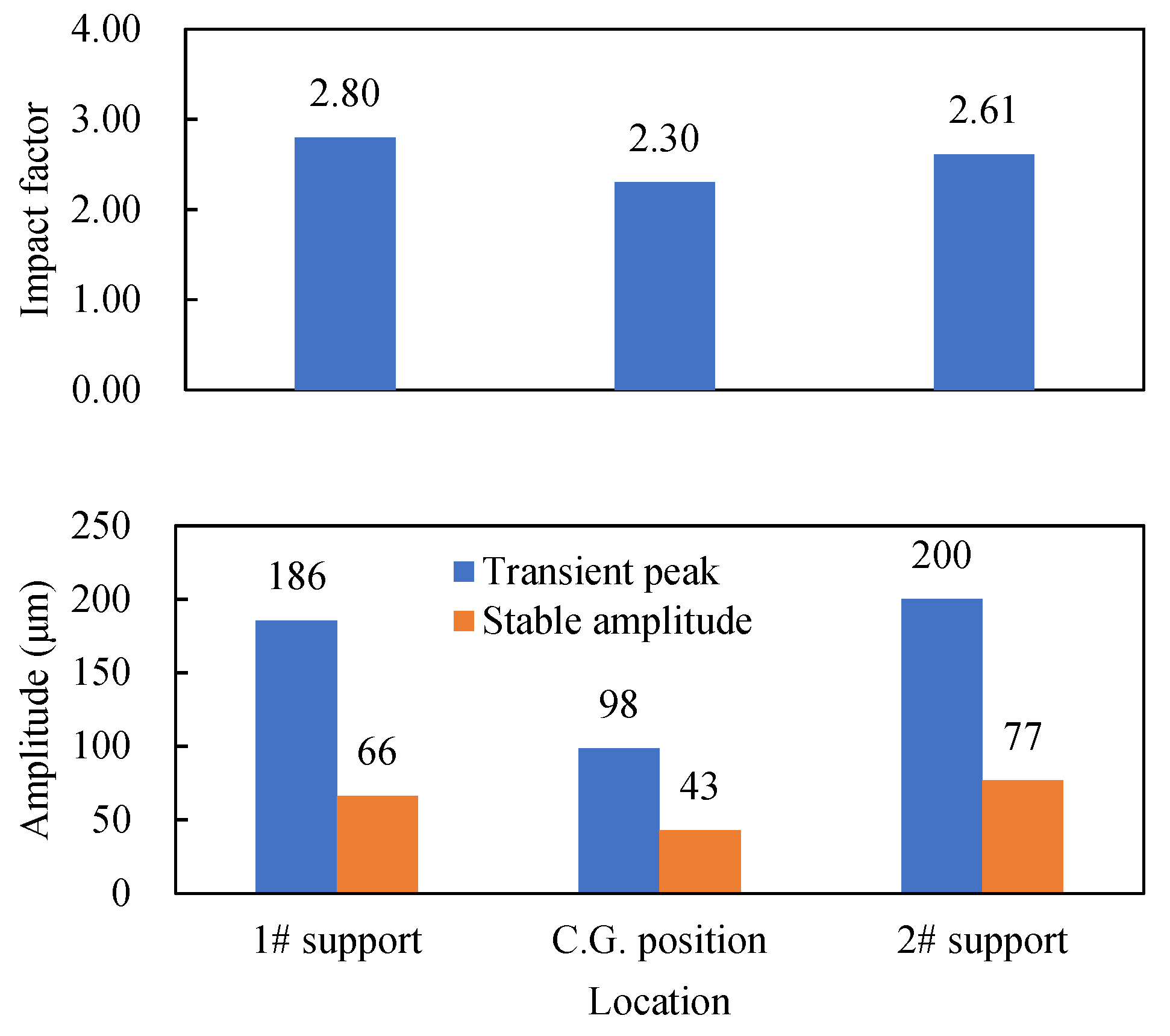
The parameter of the blade off location will not only have a significant effect on the impact factor, but also on the frequency spectrum characteristics at each node of the rotor. The transient response excited by the blade off of 1AC is greater than that caused by the loss of the 1GT blade. The sudden unbalance excitation at 1AC can excite the first three-order natural modes simultaneously (fn1, fn2, fn2+, fn3, fn3+), while the excitation at 1GT can only excite the first two modes (fn1, fn2, fn2+).
(5)
When blade off occurs at 1AC, 1# bearing and its supporting structure are most likely to be damaged and some safety design needs to be adopted because it has the largest transient and steady-state amplitude and a high impact factor.
(6)
The above-mentioned transient response time series, frequency spectrum difference, and impact factor distribution characteristics between two blade off cases can provide a good theoretical basis for the fault recognition of these complex rotors suffering from blade off. At the same time, the modeling method can be applied to other types of rotors.

Author Contributions

L.W., Writing—original draft, Investigation, Methodology, Data visualization, Validation. Y.Y.: Validation, Writing—review and editing. A.W.: Editing, Funding acquisition. X.H.: Data curation. M.J.: Data visualization, Funding acquisition. All authors have read and agreed to the published version of the manuscript.

Funding

This work was supported by the Major State Basic Research Development Program of China (No. 2013CB035706) and the Fundamental Research Funds for the Central Universities of Central South University (No. 2019zzts256).

Institutional Review Board Statement

Not applicable.

Informed Consent Statement

Not applicable.

Data Availability Statement

All data generated or analyzed during this study are included in this article.

Conflicts of Interest

The authors declare that they have no competing interests.

References

  1. Wang, N.; Liu, C.; Jiang, D. Prediction of transient vibration response of dual-rotor-blade-casing system with blade off. Proc. Inst. Mech. Eng. Part G J. Aerosp. Eng. 2019, 233, 5164–5176. [Google Scholar] [CrossRef]
  2. Heidari, M.; Carlson, D.; Sinha, S.; Sadeghi, R.; Heydari, C.; Bayoumi, H.; Son, J. An Efficient Multi-Disciplinary Simulation of Engine Fan-Blade Out Event Using MD Nastran. In Proceedings of the 49th AIAA/ASME/ASCE/AHS/ASC Structures, Structural Dynamics, and Materials Conference; Multidisciplinary Design Optimization Specialists Conference, Schaumburg, IL, USA, 7 April 2008; 2008. [Google Scholar] [CrossRef]
  3. Yu, P.; Zhang, D.; Ma, Y.; Hong, J. Dynamic modeling and vibration characteristics analysis of the aero-engine dual-rotor system with Fan blade out. Mech. Syst. Signal Process. 2018, 106, 158–175. [Google Scholar] [CrossRef]
  4. Chen, G.; Hong, J.; Ma, Y.H. Aviation gas turbine engine structure; Beihang University Press: Beijing, China, 2010. [Google Scholar]
  5. Wang, Z.Y.; Gong, B.; Wen, B.C. Research on rotor dynamics with sudden change of mass and excitation magnitude. J. Vib. Shock. 2008, 27, 48–51. [Google Scholar]
  6. Kalinowski, P.; Bargen, O.V.; Liebich, R. Vibrations of rotating machinery due to sudden mass loss. In Proceedings of the 8th IFToMM International Conference on Rotor Dynamics, Seoul, Korea, 12–15 September 2010; pp. 584–590. [Google Scholar]
  7. Genta, G. Dynamics of Rotating Systems; Springer Science & Business Media: Berlin/Heidelberg, Germany, 2007. [Google Scholar]
  8. Wang, C.; Zhang, D.; Ma, Y.; Liang, Z.; Hong, J. Dynamic behavior of aero-engine rotor with fusing design suffering blade off. Chin. J. Aeronaut. 2017, 30, 918–931. [Google Scholar] [CrossRef]
  9. Wang, C.; Zhang, D.; Ma, Y.; Liang, Z.; Hong, J. Theoretical and experimental investigation on the sudden unbalance and rub-impact in rotor system caused by blade off. Mech. Syst. Signal Process. 2016, 76-77, 111–135. [Google Scholar] [CrossRef]
  10. Li, T.; Ren, X.M.; Yue, C. Transient response of single-disc rotor system under sudden unbalance. Mech. Sci. Technol. Aerosp. Eng. 2012, 31, 924–927. [Google Scholar]
  11. Sinha, S.K. Rotordynamic analysis of asymmetric turbofan rotor due to fan blade-loss event with contact impact rub loads. J. Sound. Vib. 2013, 332, 2253–2283. [Google Scholar] [CrossRef] [Green Version]
  12. Sinha, S.K.; Dorbala, S. Dynamic Loads in the Fan Containment Structure of a Turbofan Engine. J. Aerosp. Eng. 2009, 22, 260–269. [Google Scholar] [CrossRef]
  13. Wei, J.; Bai, P.; Qin, D.; Lim, T.C.; Yang, P.; Zhang, H. Study on Vibration Characteristics of Fan Shaft of Geared Turbofan Engine with Sudden Imbalance Caused by Blade Off. J. Vib. Acoust. 2018, 140, 041010. [Google Scholar] [CrossRef]
  14. Hong, J.; Li, T.R.; Wang, Y.F.; Hong, J. Dynamic response of the aero-engine flexible rotor system under the blade-off. J. Aerosp. Power 2018, 33, 257–264. [Google Scholar]
  15. Bin, G.F.; Liao, Z.H.; Yao, J.F.; Guo, S.P. Study on blade loss vibration characteristics for low pressure rotor of 600 MW supercritical steam turbine generator units. Lubr. Eng. 2017, 42, 72–78. [Google Scholar]
  16. Li, C.; Liu, D.; Ma, Y.H.; Hong, J. Dynamic characteristics of rotor and safety design of support structure with fan blade off. J. Aerosp. Power 2020, 35, 2263–2274. [Google Scholar]
  17. Wang, L.K.; Wang, A.L.; Jin, M.; Yin, Y.J. Bistable vibration characteristics of rod fastening rotor with internal damping. China Mech. Eng. 2021, 32, 512–522, 564. [Google Scholar]
  18. Wang, L.K.; Wang, A.L.; Jin, M.; Huang, Q.K.; Yin, Y.J. Nonlinear effects of induced unbalance in the rod fastening rotor-bearing system considering nonlinear contact. Arch. Appl. Mech. 2020, 90, 917–943. [Google Scholar] [CrossRef]
  19. Wang, L.K.; Wang, A.L.; Jin, M.; Yin, Y.J.; Heng, X.; Ma, P.W. Nonlinear dynamic response and stability of a rod fastening rotor with internal damping effect. Arch. Appl. Mech. 2021, 91, 3851–3867. [Google Scholar] [CrossRef]
  20. Wang, N.F.; Liu, C.; Jiang, D.X.; Behdinan, K. Casing vibration response prediction of dual-rotor-blade-casing system with blade-casing rubbing. Mech. Syst. Signal Process. 2019, 118, 61–77. [Google Scholar] [CrossRef]
  21. Mercorelli, P. Denoising and harmonic detection using nonorthogonal wavelet packets in industrial applications. J. Syst. Sci. Complex. 2007, 20, 325–343. [Google Scholar] [CrossRef]
  22. Mercorelli, P. Biorthogonal wavelet trees in the classification of embedded signal classes for intelligent sensors using machine learning applications. J. Frankl. Inst. 2007, 344, 813–829. [Google Scholar] [CrossRef]
  23. Schimmack, M.; Mercorelli, P. A structural property of the wavelet packet transform method to localise incoherency of a signal. J. Frankl. Inst. 2019, 356, 10123–10137. [Google Scholar] [CrossRef]
  24. Schimmack, M.; Mercorelli, P. An on-line orthogonal wavelet denoising algorithm for high-resolution surface scans. J. Frankl. Inst. 2018, 355, 9245–9270. [Google Scholar] [CrossRef]
  25. Lei, B.L.; Li, C.; He, K.; Ma, Y.H.; Hong, J. Coupling vibration characteristics analysis and experiment of shared support-rotors system. J. Aerosp. Power 2020, 35, 2293–2305. [Google Scholar]
  26. Zhang, J.; Zhang, D.Y.; Wang, Y.F.; Ma, Y.H.; Hong, J. Coupling vibration characteristics analysis of shared support-rotors system. J. Beijing Univ. Aeronaut. Astronaut. 2019, 45, 1902–1910. [Google Scholar]
  27. Liao, Z.H.; Bin, G.F.; Li, C.; Yuan, W. Design method of the simulated-rotor test rig for the turboshaft engine based on the critical speed and the similarity of vibration mode. J. Mach. Des. 2021, 38, 45–50. [Google Scholar]
  28. Deng, W.Q.; Wu, S.Z.; Liu, W.K.; Sun, Y.; Tang, H.B. Support stiffness modification method for a high-speed rotor with flexible stator. J. Vib. Shock. 2020, 39, 29–35, 66. [Google Scholar]
  29. Ma, Y.H.; He, T.Y.; Zhang, D.Y.; Hong, J. Imbalance response of rotor system with nonlinear bearing stiffness. J. Aerosp. Power 2014, 29, 1527–1534. [Google Scholar]
  30. Hai, P.M.; Bonello, P. An Impulsive Receptance technique for the time domain computation of the vibration of a whole aero-engine model with nonlinear bearings. J. Sound Vib. 2008, 318, 592–605. [Google Scholar] [CrossRef]
  31. Yang, X.G.; Luo, G.H.; Wen, W.D.; Tang, Z.H.; Wang, F. Impacts of support’s nonlinear characteristics on response characteristics of dual-rotor system. J. Vib. Eng. 2014, 27, 572–582. [Google Scholar]
  32. Meng, C.; Su, M.; Wang, S.B. An Investigation on dynamic characteristics of a gas turbine rotor using an improved transfer matrix method. J. Eng. Gas Turbines Power 2013, 135, 122505. [Google Scholar] [CrossRef]
  33. Wang, L.K.; Bin, G.F.; Li, X.J.; Zhang, X.F. Effects of floating ring bearing manufacturing tolerance clearances on the dynamic characteristics for turbocharger. Chin. J. Mech. Eng. 2015, 28, 530–540. [Google Scholar] [CrossRef]
  34. Zhong, Y.E.; He, Y.Z.; Wang, Z.; Li, F.Z. Rotor Dynamics; Tsinghua University Press: Beijing, China, 1987. [Google Scholar]
  35. Ma, H.; Li, H.; Zhao, X.; Niu, H.; Wen, B. Effects of eccentric phase difference between two discs on oil-film instability in a rotor–bearing system. Mech. Syst. Signal Process. 2013, 41, 526–545. [Google Scholar] [CrossRef]
  36. Nelson, H.D. A finite rotating shaft element using Timoshenko beam theory. J. Mech. Des. 1980, 102, 793–803. [Google Scholar] [CrossRef]
  37. Wang, L.; Bin, G.; Li, X.; Liu, D. Effects of unbalance location on dynamic characteristics of high-speed gasoline engine turbocharger with floating ring bearings. Chin. J. Mech. Eng. 2016, 29, 271–280. [Google Scholar] [CrossRef]
  38. Li, Y.; Luo, Z.; Liu, J.; Ma, H.; Yang, D. Dynamic modeling and stability analysis of a rotor-bearing system with bolted-disk joint. Mech. Syst. Signal Process. 2021, 158, 107778. [Google Scholar] [CrossRef]
Figure 1. Schematic diagram of the turboshaft engine used gas generator rotors.
Applsci 11 09674 g001
Figure 2. Schematic diagram of a blade off event.
Applsci 11 09674 g002
Figure 3. Dynamic model of the rotor-support system with 18 master nodes. (a) FE model with master- and sub-elements. (b) The mechanical model equal to (a). (c) Supporting model.
Applsci 11 09674 g003
Figure 4. Assembly process for the total matrices after Guyan DOF reduction.
Applsci 11 09674 g004
Figure 5. The test rotor for the modal test. (a) Rotor model. (b) Rotor test bench.
Applsci 11 09674 g005
Figure 6. The test rig for response.
Applsci 11 09674 g006
Figure 7. The test rig for response.
Applsci 11 09674 g007
Figure 8. The first three-order mode shapes. (a) First order. (b) Second order. (c) Third order.
Applsci 11 09674 g008aApplsci 11 09674 g008b
Figure 9. Energy distribution corresponding to the first three modes. (a) First order. (b) Second order. (c) Third order.
Applsci 11 09674 g009
Figure 10. The time-domain response of 1# bearing in the horizontal direction.
Applsci 11 09674 g010
Figure 11. The time-domain response of Node 11 (C.G. position) in the horizontal direction.
Applsci 11 09674 g011
Figure 12. The time-domain response of 2# bearing in the horizontal direction.
Applsci 11 09674 g012
Figure 13. The motion orbits at different positions over time: (a) 1# bearing; (b) node 11 (C.G. position); (c) 2# bearing.
Applsci 11 09674 g013aApplsci 11 09674 g013b
Figure 14. Frequency spectrums at different locations: (a) 1# bearing; (b) node 11 (C.G. position); (c) 2# bearing.
Applsci 11 09674 g014
Figure 15. Response and corresponding impact factors at different locations.
Applsci 11 09674 g015
Figure 16. Vibration modes in different time periods: (a) 0.05–0.08 s; (b) 1–1.5 s.
Applsci 11 09674 g016
Figure 17. The time-domain response of 1# bearing in the horizontal direction when the rotor operates at 30,000 r/min: (A) 0.04–0.2 s; (B) 0.2–0.25 s; (C) 1.48–1.5 s.
Applsci 11 09674 g017
Figure 18. Frequency spectrums at different locations when the rotor operates at 30,000 r/min: (a) 1# bearing; (b) node 11 (C.G. position); (c) 2# bearing.
Applsci 11 09674 g018
Figure 19. Impact factors at different speeds.
Applsci 11 09674 g019
Figure 20. Impact factors for the blade off occurring at two different locations.
Applsci 11 09674 g020
Figure 21. Vibration modes with large unbalance due to blade off at the first stage axial compressor.
Applsci 11 09674 g021
Figure 22. Transient response (0.05 ≤ t ≤ 0.12 s) in frequency domain for the blade off occurring at two different locations: (a) 1# bearing; (b) node 11 (C.G. position); (c) 2# bearing.
Applsci 11 09674 g022
Figure 23. Unbalance response comparison obtained from simulation and test data.
Applsci 11 09674 g023
Table 1. The first three natural frequencies.
No.Simulation Result (Hz)Experimental Value (Hz)Relative Error (%)
1st order4134022.74
2nd order116411461.57
3rd order583957681.23
Table 2. Blade released parameters.
ParameterBlade Loss Mass (kg)Radius of Blade Mass Center (mm)
Value8.46 × 10−397.77
Publisher’s Note: MDPI stays neutral with regard to jurisdictional claims in published maps and institutional affiliations.

