Abstract
We aimed to increase the processing area of the roll-to-roll (R2R) nanoimprint lithography (NIL) process for high productivity, using a long roller. It is common for a long roller to have bending deformation, geometric errors and misalignment. This causes the non-uniformity of contact pressure between the rollers, which leads to defects such as non-uniform patterning. The non-uniformity of the contact pressure of the conventional R2R NIL system was investigated through finite element (FE) analysis and experiments in the conventional system. To solve the problem, a new large-area R2R NIL uniform pressing system with five multi-backup rollers was proposed and manufactured instead of the conventional system. As a preliminary experiment, the possibility of uniform contact pressure was confirmed by using only the pressure at both ends and one backup roller in the center. A more even contact pressure was achieved by using all five backup rollers and applying an appropriate pushing force to each backup roller. Machine learning techniques were applied to find the optimal combination of the pushing forces. In the conventional pressing process, it was confirmed that pressure deviation of the contact area occurred at a level of 44%; when the improved system was applied, pressure deviation dropped to 5%.
1. Introduction
Nanoimprint lithography (NIL), which was introduced by Chou in 1995, has been regarded as a promising technology with outstanding advantages. Based on the mechanical deformation of a curable resist, NIL is a fabrication method in which a substrate is coated and a desired pattern is pressed into the coating to replicate an inverse pattern [1]. Because it makes it possible to easily replicate patterns using molds with fine patterns, NIL technology is highly applicable to the manufacturing process of functional optical devices, semiconductors or display devices; it can reproduce not only micro-scale patterns but also nano-scale patterns. Recently, the fabrication of a pattern with a size of 10 nm or less by applying a nanoimprint process has been announced [2,3]. Because it has potential to pattern on a large area by the application of a step-and-repeat process, NIL is considered a next-generation patterning process that can replace photolithography [3,4,5,6].
When NIL was first introduced, an imprinted pattern was fabricated by pressing a flat mold with the pattern onto a flat substrate. However, with this method it is difficult to increase the pattern area, so it is difficult to improve productivity. To improve productivity, a new process with a long imprinting (pressing) roller with the pattern has been proposed. The roller pushes a master roller and a flexible substrate passes between the two rollers. When the substrate passes, the pattern is imprinted continuously. The process is called roll-to-roll (R2R) imprinting [7,8,9,10,11]. This process has the advantage of improving productivity, but has a disadvantage of contact pressure non-uniformity.
In general, the imprinting roller is brought close to the fixed pattern roller, and force is applied to both ends of this roller to generate imprinting pressure. Conventional R2R NIL systems inevitably cause the bending of the rollers in the pressing process, even if the roller’s axial length is relatively short. When a roller deforms, it is difficult to make a uniform pattern in the NIL process. In general, R2R NIL requires a high imprinting pressure to minimize the residual layer thickness and allow the resin to completely fill the pattern in the mold [12]. The residual layer thickness becomes an important characteristic of an imprint pattern that requires a subsequent process such as etching, and if the residual layer thickness is not uniform, the following etching profile is not uniform. As a result, the non-uniform residual film thickness causes yield loss and cost increase [13,14]. The precision of complex nano-sized patterns is demanding, and it is difficult to fill molds with resin, especially for patterns with high aspect ratios without high imprinting pressure [12].
Aarts et al. studied pressure distribution in the nip between rubber-covered rollers in a paper transport system. A mathematical model and simulation tools were implemented to determine the effects of axial pressure variation and transverse bending on the pressure distribution. Numerical results showed that the bending of the roller caused significant non-uniformity in pressure distribution [15]. Attempts to increase the imprinting pressure in the conventional R2R imprint system caused a larger bending deformation of the imprinting roller and uneven pressure along the roller, resulting in pattern defects and non-uniform residual layer thickness. To solve this problem, it is necessary to improve the conventional R2R NIL system imprinting module.
In addition, other causes have been reported for non-uniformity such as the deformation of the flexible material (skin) covering the roller, the roundness error of the roller and misalignment between the two rollers [16]. Pressure non-uniformity due to the bending deformation of the roller is generally symmetrical about the center, but pressure non-uniformity due to the above-described problem shows asymmetrical characteristics.
In this study, we try to minimize contact pressure non-uniformity in the conventional R2R NIL process with concentrated pushing force. To this end, we propose a system in which the pushing forces are distributed by several backup rollers to the imprinting roller. Additionally, the optimal combination of pushing forces is found using a machine learning technique.
2. R2R NIL Pressing System
2.1. Conventional Pressing System
For increased productivity, when applying the R2R pressing process, the axial length of the imprinting roller must be long for large-area NIL. To make conformal contact with the pattern roller on a wide substrate, a large force is applied to both ends of the imprinting roller.
As shown in Figure 1a, the imprinting module of the conventional R2R NIL system includes a master roller made of steel and an imprinting metal roller coated with rubber skin. Typically, a patterned flexible mold is wound on and adhered to the master roller and the substrate is passed between the two rollers during the process. After the resin is deposited on the substrate, the mold pattern on the master roller is duplicated on the resin-coated substrate by the application of a force to external force points and of the imprinting. The two forces generate the contact pressure between the substrate and the pattern roller. At this time, bending deformation of the imprinting roller occurs, which causes non-uniform pressure distribution on the contact area. This can be predicted through simple static modeling, as shown in Figure 1b.

Figure 1.
Conventional R2R NIL pressing process: (a) Imprinting module of conventional R2R NIL system; (b) Free body diagram of conventional R2R NIL pressing process.
Roller bending deformation is usually the largest contributor to nip pressure variations across the width. As seen in Figure 2, all end-loaded rollers will deflect and bow away from the nip, which causes pinching at the ends. Indeed, non-uniformity is caused on the metal roller’s nips. Even with only about the outer 10–20% of the ends in contact, there will be a gap in the center. Rubber coating on the imprinting roller can help even out the nip load variation; however, the tendency is still there [16].
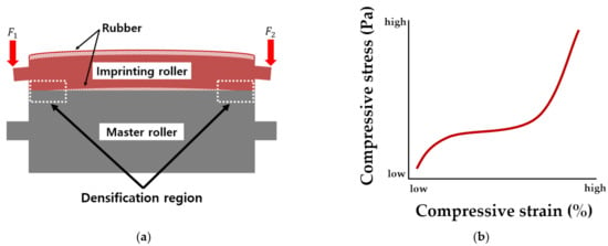
Figure 2.
(a) Roller bending deformation of imprinting roller when pushing against master roller; the master roller’s deformation is ignored, and the imprinting roller has rubber skin. (b) The curve of the compressive measure for rubber.
As shown in Figure 2b, stress–strain characteristics for rubber are mainly divided into three different regions. First, there is a linear deformation region where the stress linearly increases with the increase in strain. Second, a plateau region occurs, indicating that the stress remains constant despite the change in strain. Third, there is a densification region where the stress dramatically increases as the strain increases [17]. As shown in Figure 2a, the area at both ends of the rubber layer (skin) is densified due to the bending deformation of the roller. It can be seen that in this densification region, the pressure distribution in the contact area increases dramatically due to the high compressive elastic modulus of rubber.
Calculating the imprinting roller (rubber–steel composite) bending deformation and the contact pressure variation and the flexural properties is difficult [18,19,20,21]. Therefore, numerical solutions such as finite element modeling (FEM) analysis were used to analyze the mechanical behavior of composites [16,22].
Using the static structural analysis of ANSYS (analysis system) 2019 R3, FEM analysis was performed, as shown in Figure 3a, to check the non-uniform pressure distribution at the contact area between the master roller and the imprinting roller due to bending deformation during the pressing process. The specifications of the imprinting roller and the master roller used in the analysis are the same as the conventional system (PNT, R2R NIL system) specifications used in the industry. For efficient and accurate analysis, the global mesh was generated with coarse size, and the area of interest where the contact occurred was generated with the element size set to fine size. The area of interest was generated as a hexahedral element with the mesh size set to 2 mm. It can be confirmed from Figure 3b that when pressing both ends of the imprinting roller with a total force of 4000 N, the ends of the contact area showed a high pressure and the center of the roller showed a low pressure. Generally, the material properties in the FE analysis are assumed to be elastic and the conditions are ideal; however, the physical properties of the rubber skin were not accurate and the conditions are not ideal. Therefore, verification was conducted through an actual experiment.

Figure 3.
Pressure distribution along roller during simulation (FEM): (a) Imprinting module of conventional R2R NIL used in simulation (FEM); (b) Distributed pressure on the contact area.
An imprint pressing experiment was conducted to confirm the non-uniform pressure distribution on the contact area, the nip between the master roller and the imprinting roller, due to bending deformation during the actual pressing process. The experiment was conducted using a large-area R2R NIL system; the pressure and pressure distribution at the contact area were measured using a pressure measurement film (PMF, Model PRESCALE LLLW, Fujifilm, Tokyo, Japan). The experimental equipment and configuration are shown in Figure 4a. The pressure distribution was measured upon the master roller after pressing with 200kgf by using each of the pneumatic cylinders installed at both ends of the imprinting roller.

Figure 4.
Imprinting module of conventional R2R NIL system used in experiments: (a) Setup of pressure measurement film on conventional R2R NIL system for experiments; (b) Pressure distribution along roller.
The measurement results are shown in Figure 4b. After the pressing process, the PMF experienced color change. The change was analyzed and then averaged over an area, 1 , to transform to the measured pressure value. Since the actual measured values contain noise, the measured data were fitted using MATLAB; through this, it was found that the measured pressure at both ends of the contact area tends to be higher than the value at the center. However, the pressure at the central part is low and at both ends the pressure tends to be high compared to the value in FE analysis. Additionally, the maximum values of the pressure at the two ends are not the same in the real situation. However, the tendency of the pressure distribution from the central part toward both ends appears to be similar to the FE simulation. In Figure 3b, the contact pressure does not have a symmetrical distribution about the center of the roller. This means that other causes are involved.
Other than the bending, there are three more reasons why non-uniform pressure distribution exists when pressing the roller. During the pressing process, there are roller skin deflection, waviness error in the contact area due to roundness error and the straightness error of the roller and roller misalignment [16]. Other than roller deflection, all factors are caused during system manufacture. The best way to improve these problems is to improve the manufacturing process. However, to improve these problems, it is necessary to use precision machining and a precise assembly process, and thus the cost may be very high.
The waviness error of the roller causes a problem in which contact is not made uniformly during the pressing process; this can be improved to a certain degree by using the rubber skin coating on the surface of the imprinting roller. However, the combination of roller misalignment and roller skin deflection causes non-uniform pressure distribution on the contact area, and because the roller rotates during the imprinting process, the pressure distribution changes with the passage of time.
Therefore, there is a limitation to using the conventional roller pressing system to eliminate contact pressure non-uniformity.
2.2. New Large-Area R2R NIL Uniform Pressing System
The non-uniform pressure distribution caused by the bending deformation of the roller generated by the concentrated load at both ends can be improved by adding a load to the center of the roller. Additionally, the non-uniform pressure distribution by the rubber skin deflection, the waviness error and the misalignment of the rollers can be improved by dividing the three loads into several and controlling each of the divided loads.
The configuration of the large-area R2R NIL uniform pressing module to reflect this method is shown in Figure 5a. It has the same specifications of the imprinting roller, master roller and pressing module as the equipment used in the previous experiment in Figure 4a. Each backup roller is configured to be driven independently by installing a servo motor, which is an actuator. The system includes a guide roller made of steel to prevent deformation and fatigue damage of the rubber skin of the imprinting roller due to pressing by the backup rollers. All the actuators capable of applying a load include a load cell sensor that can measure the load value, so that individual load values can be measured and controlled when pressed. Figure 5b shows a large-area R2R NIL uniform pressing system that has actually been implemented.
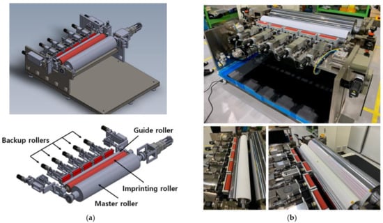
Figure 5.
Large-area R2R uniform pressing system capable of independent pressing: (a) Design of large-area R2R uniform pressing system; (b) Appearance of large-area R2R uniform pressing system.
Figure 6 shows the integrated control system. Each actuator that applies a load during pressing is configured to enable integrated control in the control PC using a servo driver and motion controller (Model SPiiPlusES, ACS Motion Control, Yokne’am Illit, Israel). In addition, the pressure value of each load cell sensor and the pressure value of the pneumatic cylinders are configured to be checked in real time from the control PC through the I/O module.
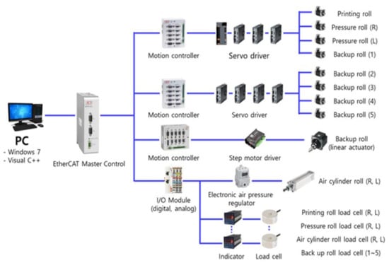
Figure 6.
Configuration of the control system for large-area R2R uniform pressing system.
This system was originally designed to eliminate contact pressure non-uniformities in real time. The non-uniformities caused by the bending deformation of the roller cannot be controlled by the load concentrated on both ends of the roller alone. Since adding one pressing roller in the center of the rollers could not solve the problems from roller skin deformation, waviness error and misalignment of the rollers, more pressing rollers were arranged. As the roller rotates, the deformation due to the error factors changes dynamically over time. Controlling this dynamic change is the ultimate goal of this system, but here we first try to solve the non-uniformity in the static state. The data obtained here will be used for dynamic control in the future.
3. Experiment for Uniform Pressure Distribution
3.1. Improving Uniformity Using the Center Roller
It was confirmed by conducting an experiment whether the individual backup roller applied to the large-area R2R uniform pressing system can affect the pressure distribution at the contact area during the actual pressing process. The experimental conditions were that the sum of the loads applied during pressing was 400 kgf, which is the sum of the load applied by the pneumatic cylinder installed at both ends of the imprinting roller and the load applied by the servo motor of the backup roller. The experiment was conducted using only one backup roller in the center of the roller span under the condition that the total sum of the loads did not change.
Figure 7 shows the results of the uniform pressure test using the backup roller. Figure 7a shows the result of applying loads of 170 kgf to both ends of the imprinting roller and 60 kgf to the center backup roller. In Figure 7b, 140 kgf was applied to both ends of the imprinting roller, and 120 kgf was applied to the center backup roller; in Figure 7c, 100 kgf was applied to both ends of the imprinting roller, and 200 kgf was applied to the center backup roller. It can be seen that the center backup roller can improve the pressure distribution uniformity on the contact area when it is actually pressed.
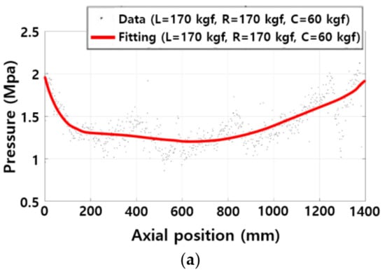

Figure 7.
Pressure distribution along roller using center backup roller pressing: (a) Left force 170 kgf, right force 170 kgf and center force 60 kgf; (b) Left force 130 kgf, right force 130 kgf and center force 140 kgf; (c) Left force 100 kgf, right force 100 kgf and center force 200 kgf.
It can be seen from Table 1 that, for various reasons such as skin deflection, waviness error and misalignment of the roller, it is difficult to press and obtain uniform pressure on the contact area with only the one center backup roller. As shown in Figure 5, even when a backup roller is installed in the center of the roller and pressure is applied, asymmetric non-uniform pressure distribution occurs in the contact area. This is caused by other factors such as the deformation of the roller skin, waviness error, misalignment of the rollers, etc. In consideration of this, the proposed system has five backup rollers and two actuators at both ends for an individual pressing mechanism in which more backup rollers are driven systematically. Because of the more number of rollers, numerous roller pressing force combinations exist for uniform pressure distribution. Since it would take a lot of time to test this large number of cases only by experiment, we intend to use machine learning techniques to derive the optimal uniform pressing conditions based on the results of pressing experiments.

Table 1.
Maximum and minimum pressure values and non-uniformity with only the center roller.
3.2. Improving Uniformity Using Multiple Rollers and Machine Learning
The most commonly used machine learning algorithms automate the decision-making process by creating generalized models based on known examples. This approach is called supervised learning: it provides inputs and expected outputs to the algorithm, and the algorithm finds a way to produce the desired output from the given inputs. This type of learned algorithm can produce an appropriate output from an arbitrary input. In supervised learning, there are processes of classification and regression. Classification is the prediction of one from several predefined, possible class labels. Regression predicts a continuous number. It is easy to distinguish between regression and classification problems based on whether the output has continuity or not [23].
In the large-area R2R uniform pressing system, the load value applied by the actuators during the pressing process was set as an input value and the pressure distribution value at the contact area was set as an output value. Regression analysis was performed assuming that the output values have continuity. The output value of the input value without the experimental result was predicted through the regression analysis supervised learning of the input value obtained by a relatively small number of experiments.
For this, the sensor for measuring the pressure distribution on the contact area was replaced with an electronic pressure measurement sensor (Model 5555, Tekscan), which can be analyzed in real time. The electronic pressure measurement sensor is shown in Figure 8a; this sensor uses the same measurement principle as the strain gage. The experiment was set up as shown in Figure 8b; three sensors were connected to measure the entire area of contact between the master roller and the imprint roller. In addition, the un-measured area between the connected sensors was predicted and measured using an interpolation method.
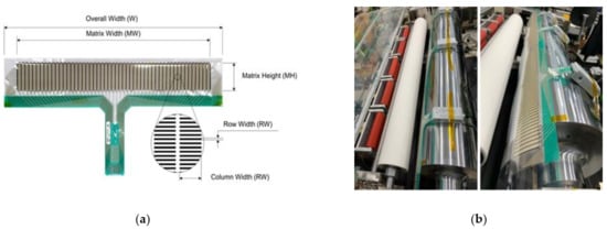
Figure 8.
Large-area R2R uniform pressing system used in experiments: (a) Electronic pressure measurement sensor; (b) Setup of electronic pressure measurement sensors on large-area R2R uniform pressing system.
In this study, we try to make the contact pressure of the rollers uniform under static conditions. The contact pressure of the master roller is divided into the left (, the center ( and the right (, and the uniformity is evaluated based on the average value of these areas. If the deviation of these values is not large, it is assumed that the uniformity is secured. To reduce this deviation, the pushing force of the left pneumatic cylinder (), the pushing forces of each backup roller (~) and the pushing force of the right pneumatic cylinder () should be optimally selected. Therefore, the inputs of supervised learning were set as , ~ and , and the outputs were set as , and .
If one output continuously changes with respect to one input, it can be determined that several outputs for several inputs also change continuously. Here, is selected as the input and is selected as the output. The relationship between them was regression-analyzed using the random forest method.
The experimental condition is such that the sum of the input pushing forces is 400 kgf, which is the sum of the forces applied by the pneumatic cylinders installed at both ends of the imprinting roller and the servo motors of the backup rollers. As shown from the left in Figure 9, the force at both ends of the imprint roller was set to , and the load of the center backup roller was set to , ~. The average values of the electronic pressure measurement sensors were set, from the left, to , and . The test conditions were 400 kgf in total force, and the ratio of the force value of the center backup roller was increased from 0~44%. In Figure 10, the output value data measured in the center are expressed in a boxplot. Regression analysis was conducted using the force of the center backup roller () and the average value of the center electronic pressure measurement sensor (). Linear regression, decision tree and random forest techniques were applied as basic regression analysis methods. Since the amount of analysis was not large, there was no significant difference in efficiency. The random forest technique with the highest training/test scores and improved reliability was applied. The applied random forest algorithm is shown in Equation (1). For , draw a bootstrap sample of size from the training data. Grow a random forest tree to the bootstrapped data, by recursively repeating the following steps for each terminal node of the tree, until the minimum node size is reached. As each individual model is built, variables are randomly selected from all variables, and the best variable/split point combination is chosen. Then, split the node into two daughter nodes [24]. Output the ensemble trees . To make a prediction at a new point :
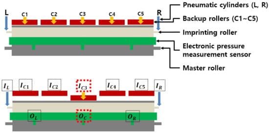
Figure 9.
Schematic diagram of large-area R2R uniform pressing system for experiments; three output pressing forces (, and ) are selected to check the uniformity by the input pushing forces (, , ~ and ). Firstly, ’s change is investigated by engaging only.
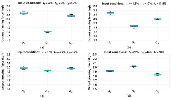
Figure 10.
Experimental results for regression analysis; output pressing force from left (), central () and right () sections of roller for the inputs: (a) Left force 200 kgf, right force 200 kgf; (b) Left force 165 kgf, right force 165 kgf and center force 70 kgf; (c) Left force 148 kgf, right force 148 kgf and center force 104 kgf; (d) Left force 112 kgf, right force 112 kgf and center force 176 kgf.
The regression analysis algorithm used the random forest algorithm provided by Scikit-learn, a Python machine learning library. Random forest regression analysis was performed as shown in Figure 11 to check whether the change in the output value has continuity according to the change in the input value. The total data volume used for training is 1520 sets, and the analysis was performed by adjusting the max depth of the hyper-parameter provided by Scikit-learn. Based on the training data, the random forest algorithm learned the correlation between the input and the output. As a result of learning, the average train score was 0.990 and the test score was 0.953. It was confirmed that there is continuity between them and the learning data followed the actual experimental data well. Therefore, the output value can be predicted for an input value for which the actual experiment was not conducted.
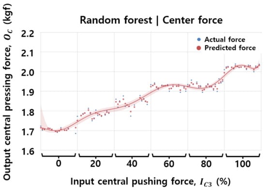
Figure 11.
Random forest regression analysis result of output () value according to input () value.
Regression analysis was performed on all input values applied by the pneumatic actuators at both ends of the imprinting roller and the actuators of the five backup rollers. Random forest regression analysis was performed for all inputs (, ~ and ) and for all outputs (, and ). The results of the performed regression analysis can be used to find an optimal combination of the input pushing force for the minimum difference of the output pressing forces. A combination of input values whose output value has a range of was found using the for statement. Figure 12 is a box plot showing input values that can be used to derive an output value having a range of , which is a uniform pressure distribution value at the contact area. Table 2 shows the maximum and minimum values and average values of the derived input values, as shown in Figure 12b.

Figure 12.
Optimal pressing for uniformity using multi regression analysis: (a) Output value with uniform pressing force (; (b) Input value optimization result of input pushing force.

Table 2.
Optimized load value of Figure 11b.
Figure 13 shows the experimental results obtained using the optimal input values found through the derived regression analysis. It was confirmed that the experimental result values coincide at a 95% level with the result in the regression analysis learning.
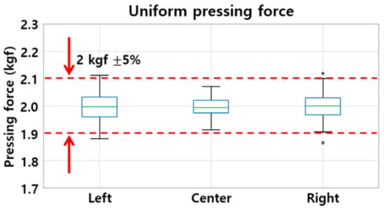
Figure 13.
Force distribution experiment results along rollers using regression analysis results.
4. Conclusions
The purpose of this study is to reveal the contact pressure non-uniformity problem of the conventional R2R NIL system and to propose a system to improve it. Simple modeling, FEM analysis and experiments were conducted to reveal the problem. In order to improve the problem, a new pressing system was proposed, and the experiment and optimization showed that the contact pressure was equalized. In the optimization process, machine learning regression analysis was used.
In the conventional R2R NIL system, the pressing process is mainly performed by applying concentrated loads to both ends of the roller during the pressing process for imprinting. For high productivity, the axial length of the imprinting roller must be long; the contact area increases due to the lengthened roller, and a higher pressing force is required. If the conventional pressing process is applied to a large-area R2R NIL system, the pressure distribution on the contact area is not uniform during imprinting due to the bending of the roller. If the rubber skin of the roller is deformed, if there is a waviness error in the contact area or if rollers are misaligned, this non-uniformity of the contact pressure becomes severe. In this study, a new roller pressing system, which applies a distributed load to the entire roller, was applied. The proposed system is different from the method of applying concentrated loads at both ends, which is the conventional pressing method.
In the conventional R2R NIL pressing process, the bending of the roller is predicted through mathematical modeling and simulation (FEM). Through actual experiments, it was confirmed that the conventional R2R NIL system has a non-uniform pressure distribution at an 85% level during the pressing process on the contact area. In addition, it was checked that the non-uniformity is not symmetrical, which means the other errors are engaged.
A uniform pressing system was designed and implemented to perform pressing by individual and distributed load. It was confirmed that the pressure distribution uniformity of the contact area can be improved to a level of 33% by improving the bending of the roller via pressing the backup roller, which is the core mechanism of this system. A number of backup rolls were used to improve the uniformity of the pressure distribution, which was irregular due to the other errors from skin, waviness error in the contact area and misalignment. The effect of each backup roller on the pressure distribution of the contact area was learned and analyzed using regression analysis of supervised learning, a machine learning technique. Using the results of regression analysis, the optimum force of each backup roller was found. As a result of testing by applying the derived value, it was confirmed that the uniformity of the pressure distribution on the contact area can be improved to a level of 5%.
In this research, to utilize the machine learning technique (regression), the pressure distribution value at the contact area was divided into three sections and averaged. To more closely measure the pressure distribution at the actual contact area, the average interval needed to be divided further. The proposed pressing system is designed to control the non-uniformity of the contact pressure in real time, but in this study, only the uniformity in the static state was studied. In the future, to perform compensation control in a dynamic state, these improvements can be used.
In spite of the limitations of the method, it was confirmed that the non-uniformity of the pressing process, one of the biggest issues for increased productivity and yield in large-area R2R NIL, can be improved by applying the system developed in this study. This method is expected to contribute to productivity and yield improvement of the NIL process.
Author Contributions
Conceptualization, project administration, supervision, funding acquisition, writing—review and editing, S.K.; conceptualization, project administration, supervision, validation, writing—review and editing, M.G.L.; formal analysis, data curation, visualization, investigation, writing—original draft, G.E.K.; data curation, visualization, software, investigation, H.K.; investigation, formal analysis, validation, K.W.; formal analysis, investigation, Y.K.; validation, resources, S.-H.L.; project administration, validation, methodology, Y.J. All authors have read and agreed to the published version of the manuscript.
Funding
This study is based on work supported by the Ministry of Trade, Industry, and Energy (MOTIE, Korea) under the Industrial Technology Innovation Programs (No. 20000665, No. N0002310); the National Research Foundation of Korea (NRF) funded by the Korean government (No. 2021M3H4A3A01050374, No. 2020M3H4A3106319).
Institutional Review Board Statement
Not applicable.
Informed Consent Statement
Not applicable.
Data Availability Statement
Not applicable.
Conflicts of Interest
The authors declare no conflict of interest.
References
- Chou, S.; Krauss, P.R.; Renstrom, P.J. Imprint of sub-20 nm vias and trenches in polymers. Appl. Phys. Lett. 1995, 67, 3114–3116. [Google Scholar] [CrossRef]
- Austin, M.D.; Ge, H.; Wu, W.; Li, M.; Yu, Z.; Wasserman, D.; Lyon, S.A.; Chou, S. Fabrication of 5 nm line width and 14 nm pitch features by nanoimprint lithography. Appl. Phys. Lett. 2004, 84, 5299–5301. [Google Scholar] [CrossRef]
- Wu, W.; Tong, W.M.; Bartman, J.; Chen, Y.; Walmsley, R.; Yu, Z.; Xia, Q.; Park, I.; Picciotto, C.; Gao, J.; et al. Sub-10 nm nanoimprint lithography by wafer bowing. Nano Lett. 2008, 8, 3865–3869. [Google Scholar] [CrossRef]
- Cho, Y.T.; Jung, Y.G. A Study on the expectation of residual layer thickness in roller pressing imprinting process. KSMPE 2013, 12, 104–109. [Google Scholar]
- McMackin, I.; Choi, J.; Schumaker, P.; Nguyen, V.; Xu, F.; Thompson, E.; Babbs, D.; Sreenivasan, S.V.; Watts, M.; Schumaker, N. Step and repeat UV nanoimprint lithography tools and processes. Proc. SPIE 2004, 5374, 222–231. [Google Scholar]
- Ahn, S.H.; Guo, L.J. Large-area roll-to-roll and roll-to-plate nanoimprint lithography: A Step toward high-throughput application of continuous nanoimprinting. ACS Nano 2009, 3, 2304–2310. [Google Scholar] [CrossRef] [PubMed]
- Kooy, N.; Mohamed, K.; Guan, O.S. A Review of roll-to-roll nanoimprint lithography. Nanoscale Res. Lett. 2014, 9, 320. [Google Scholar] [CrossRef]
- Ok, J.G.; Youn, H.S.; Kwak, M.K.; Lee, K.T.; Shin, Y.J.; Guo, L.J.; Greenwald, A.; Liu, Y. Continuous and scalable fabrication of flexible metamaterial films via roll-to-roll nanoimprint process for broadband plasmonic infrared filters. Appl. Phys. Lett. 2012, 101, 223102. [Google Scholar] [CrossRef]
- Kang, M.G.; Park, H.J.; Ahn, S.H.; Guo, L.J. Transparent Cu nanowire mesh electrode on flexible substrates fabricated by transfer printing and its application in organic solar cells. Sol. Energy Mater. Sol. Cells 2010, 94, 1179–1184. [Google Scholar] [CrossRef]
- Ahn, S.H.; Kim, J.S.; Guo, L.J. Bilayer metal wire-grid polarizer fabricated by roll-to-roll nanoimprint lithography on flexible plastic substrate. J. Vac. Sci. Technol. B Microelectron. Nanometer Struct. Process. Meas. Phenom. 2007, 25, 2388–2391. [Google Scholar] [CrossRef]
- Bae, S.K.; Kim, H.K.; Lee, Y.B.; Xu, X.; Park, J.S.; Zheng, Y.; Balakrishnan, J.; Lei, T.; Kim, H.R.; Song, Y.I.; et al. Roll-to-roll production of 30-inch graphene films for transparent electrodes. Nat. Nanotechnol. 2010, 5, 574. [Google Scholar] [CrossRef]
- Lee, H. Effect of imprinting pressure on residual layer thickness in ultraviolet nanoimprint lithography. J. Vac. Sci. Technol. B Microelectron. Nanometer Struct. Process. Meas. Phenom. 2005, 23, 1102–1106. [Google Scholar] [CrossRef]
- Lee, H.J.; Ro, H.W.; Soles, C.L.; Jones, R.L.; Wu, W.I. Effect of initial resist thickness on residual layer thickness of nanoimprinted structures. J. Vac. Sci. Technol. B Microelectron. Nanometer Struct. Process. Meas. Phenom. 2005, 23, 3023–3027. [Google Scholar] [CrossRef]
- Sun, H.W.; Wang, W.Y.; Wang, H.B.; Qi, B.S. Impact of imprint pressure on residual layer thickness in UV nanoimprint lithography. DEStech Trans. Comput. Sci. Eng. 2019. [Google Scholar] [CrossRef][Green Version]
- Aarts, A.C.T.; van Eijndhoven, S.J.L.; Saes, L.H.; Clevers, E. The pressure distribution in nips of systems of flexible rubber-covered rollers. Int. J. Mech. Sci. 2012, 64, 155–164. [Google Scholar] [CrossRef]
- Roisum, D.R. The Mechanics of Web Handling, 1st ed.; TAPPI PRESS: Atlanta, GA, USA, 1998; pp. 119–126. [Google Scholar]
- Xiang, B.; Jia, Y.; Lei, Y.; Zhang, F.; He, J.; Liu, T.; Luo, S. Mechanical properties of microcellular and nanocellular silicone rubber foams obtained by supercritical carbon dioxide. Polym. J. 2019, 51, 559–568. [Google Scholar] [CrossRef]
- Caminero, M.Á.; Romero, A.; Chacón, J.M.; Núñez, P.J.; García-Plaza, E.; Rodríguez, G.P. Additive manufacturing of 316L stainless-steel structures using fused filament fabrication technology: Mechanical and geometric properties. Rapid Prototyp. J. 2021, 27, 583–591. [Google Scholar] [CrossRef]
- Wang, Z.; Shen, H.; Wu, S.; Fu, J. Colourful fused filament fabrication method based on transitioning waste infilling technology with a colour surface model. Rapid Prototyp. J. 2021, 27, 145–154. [Google Scholar] [CrossRef]
- Travieso-Rodriguez, J.A.; Jerez-Mesa, R.; Llumà, J.; Gomez-Gras, G.; Casadesus, O. Comparative study of the flexural properties of ABS, PLA and a PLA–wood composite manufactured through fused filament fabrication. Rapid Prototyp. J. 2021, 27, 81–92. [Google Scholar] [CrossRef]
- Luke, S.S.; Soares, D.; Marshall, J.V.; Sheddden, J.; Keleş, Ö. Effect of fiber content and fiber orientation on mechanical behavior of fused filament fabricated continuous-glass-fiber-reinforced nylon. Rapid Prototyp. J. 2021, 27, 1346–1354. [Google Scholar] [CrossRef]
- Cereda-Avila, S.N.; Medellín-Castillo, H.I.; Lim, T. Analytical models to estimate the structural behaviour of fused deposition modelling components. Rapid Prototyp. J. 2021, 27, 658–670. [Google Scholar] [CrossRef]
- Müller, A.C.; Guido, S. Introduction to Machine Learning with Python: A Guide for Data Scientists, 1st ed.; O’Reilly Media: Sebastopol, CA, USA, 2017; pp. 53–171. [Google Scholar]
- Kosorok, M.R.; Freeman, N.B.; Leete, O.E. Precision Medicine: Lecture 03 Machine Learning; Department of Biostatistics lecture note; Gillings School of Global Public Health University of North Carolina: Chapel Hill, NC, USA, 2019. [Google Scholar]
Publisher’s Note: MDPI stays neutral with regard to jurisdictional claims in published maps and institutional affiliations. |
© 2021 by the authors. Licensee MDPI, Basel, Switzerland. This article is an open access article distributed under the terms and conditions of the Creative Commons Attribution (CC BY) license (https://creativecommons.org/licenses/by/4.0/).