Article

Development and Performance Evaluation of an Integrated Disc Cutter System for TBMs

1
School of Mechanical Engineering, Dalian University of Technology, Dalian 116024, China
2
China Railway Engineering Equipment Group Co., Ltd., Zhengzhou 450016, China
3
School of Mechanical Engineering, Harbin Institute of Technology, Shenzhen 518055, China
*
Authors to whom correspondence should be addressed.
Appl. Sci. 2021, 11(2), 644; https://doi.org/10.3390/app11020644
Submission received: 16 December 2020 / Revised: 6 January 2021 / Accepted: 7 January 2021 / Published: 11 January 2021
(This article belongs to the Section Mechanical Engineering)

Abstract

:
Changing the cutter is an essential procedure in tunnel boring machine (TBM) operations. The danger and low efficiency of manually replacing the disc cutter has led engineering equipment designers to study technologies to automate the changing of cutters. The key step is to design a new integrated disc cutter (simplifying the replacement process) to facilitate robot operation. Until now, the design and research of new integrated disc cutter systems has mainly relied on inspiration. In this paper, a solution space of a certain configuration of an integrated disc cutter system based on topology theory was designed. The evaluation system for the solution space was constructed by the analytic hierarchy process (AHP), and the optimal scheme of the configuration was finally obtained. In addition, experiments and simulations show that the structural strength and anti-loosening performance of the new disc cutter system meet the engineering requirements. Application of topology theory and the new evaluation system provides useful theoretical analyses and guidance for the design of new cutter systems.

1. Introduction

Tunnel boring machines (TBMs) have become the main tool of tunnel construction because of their high efficiency and safety compared with traditional blasting methods [1]. Disc cutters are parts that are distributed on TBM cutterheads according to certain rules. The weight of a 19 inch disc cutter is about 179 kg, as shown in Figure 1. As the key cutting tool of TBMs, the disc cutter acts directly with rock or soil, which easily causes it to experience wear or damage in the working process [2]. Some scholars have developed prediction models to calculate the performance of the disc cutter, which improves the safety of TBM construction to a certain extent [3,4,5,6]. Therefore, to make TBMs reliable, replacing the disc cutter is an essential process in TBM operation. However, the replacement tasks currently rely on manual work. The workers who change cutters are exposed to muddy water, high pressure, tunnel collapse, rock burst, and other problems when they are performing cutter-changing tasks underground. According to statistics, accidents due to cutter-changing operations have become the main source of accidents in the process of tunnel construction [7]. In addition, the changing processes occupy over a third of the whole construction period [8]. The same problems are experienced with micro tunnel boring machines (MTBMs), where the difficulties of changing disc cutters are higher due to the reduced dimensions of the tunnels: It takes 2 or 3 days to replace the cutters [9,10]. The danger and low efficiency of manually changing disc cutters has encouraged engineers to study technologies for the automatic changing of disc cutters.
The research into technologies for the automatic changing of cutters is mainly divided into two popular topics. The first is the study of heavy-load robots to change cutters (load greater than 400 kg), which can adapt to the narrow space of the TBM and high pressure and high humidity environments [11]. Its function is to disassemble and transport the old and new cutters. Initially, scholars and enterprises [11,12] used the traditional industrial robot body (6R) and installed a special end to implement cutter changes. The advantage of this kind of approach is that it can realize many kinds of actions. However, due to the limited space in the TBM and the load ratio of industrial robots, the cutter changing range of traditional industrial robots is limited, so they are not used in engineering applications. Recently, researchers [13,14,15,16,17,18] have begun to design other robot configurations (Combination of R and P) to achieve large load ratios and large working ranges. However, the disadvantage of this kind of robot is that its disassembly and assembly actions are relatively simple. Therefore, the second hot topic for the automatic changing of cutters is to design a new integrated cutter system to adapt to the disassembly and assembly of a robot with sample actions.
The traditional cutter system (TCS) has various kinds of parts, such as bolts, screw locking blocks, fixing blocks, and cutters, as shown in Figure 2. Obviously, the disassembly and assembly of the TCS is complex. Therefore, it is necessary to design an integrated cutter system (ICS) that is easy for a robot with low flexibility to disassemble and assemble. The French companies BOUYGUES and NFM [12] launched a link-slider mechanism type ICS, which does not require the structure of the cutter head to be changed. Moreover, the interface of the ICS is relatively simple. The Robot Innovation Center of the German Research Center for Artificial Intelligence (DFKI) [14] developed a slider-type ICS that has the advantages of a large impact load and simple interface at the end of the robot. HongRun Construction Group Co., Ltd. [11] proposed an ICS that uses an eccentric circle mechanism to lock the cutter.
In summary, most of the schemes created by scholars and enterprises thus far were designed through inspiration or experience, and no scholar systematically analyzed the configuration and scheme of the new cutter system from the perspective of topology theory. The performance evaluation method of the cutter system has not been established in industry, so it is impossible to determine the merits of different schemes. Therefore, this paper proposes an integrated cutter system configuration design method based on topology theory and obtains the solution space of one configuration of the integrated cutter. At the same time, the analytic hierarchy process (AHP) is used to construct the evaluation system of the solution space. The discriminant matrix was obtained from 30 TBM design experts, which has engineering-guidance significance. Through the evaluation system, the optimal scheme of a certain configuration can be obtained. Finally, a simple experiment was designed to verify the anti-loosening performance of the new cutter system. The contribution of this paper is as follows:
  • A design method of the ICS configuration based on topology theory is presented, which can obtain all schemes under this configuration.
  • Combined with engineering experience and the AHP, the evaluation system of the ICS is established.
  • A simple experiment suitable for verifying the tightening performance of the ICS is innovatively designed.
The rest of this paper is organized as follows: Section 2 is the design flow of the new integrated cutter system based on topology theory. The establishment process of the evaluation system of the integrated cutter system is described in Section 3. Section 4 shows the anti-loosening design of the scheme. The experimental verification of the anti-loosening performance is carried out in Section 5. The last section includes the summary and limitations.

2. Scheme Design of Integrated Cutter Systems

2.1. Design Objectives

According to the working environment of the ICS and the requirements for cutter changing robots, the following design requirements are proposed for the TBM ICS.
  • The removal and installation of the ICS should be as simple as possible to reduce the action of the end effector of the cutter changing robot and improve the efficiency of the cutter replacement process.
  • The ICS must have good mechanical properties to ensure that it can work in a dangerous, high stress, and alternating load environment for a long time.
  • Severe vibration during TBM operation will loosen the ICS, which can lead to a sharp decline in the lifespan of a cutter. Consequently, it is vital to improve the fastening performance of the ICS.

2.2. Mechanism Type Synthesis Based on Mechanism Topology Theory

This paper takes six-bar single-degree-of-freedom as an example to illustrate the novel integrated cutter system design method based on the theory of planar topological mechanisms.

2.2.1. Solution for the Kinematic Chain and Mechanism Diagram

From mechanism theory [19], the degrees of freedom of the kinetic chain and mechanism are indicated in Equations (1) and (2), respectively.
F k = 3 ( n k 1 ) 2 P k ,  
W k = 3 n k 2 P k ,
where Fk is the degree of freedom of the mechanism, Wk is the degree of freedom of the kinetic chain, nk is the number of mechanism components, and Pk is the number of kinematic pairs of the mechanism.
When the mechanism contains multiple joints, the multiple joints factor can be obtained by Equation (3).
v k = K f ( K f 1 ) P f ,
where vk is the multiple joints factor, Kf is the number of overlapped joints in the multiple joints, and Pf is the number of multiple joints composed of Kf overlapped joints.
The relationship between the number of members with i kinematic pairs and Pf and vk can be obtained by Equation (4).
max i n i = 2 P f v k ,
where ni is the number of members with i kinematic pairs.
The number of closed chains in the mechanism can be described by Equation (5).
L k = P k n k + 1 ,  
where Lk is the number of closed chains in the mechanism.
The relationship between ni and nk can be seen from Equation (6).
max n i = n k ,
from Equation (4)×3 Equation (2), n2 can be obtained by Equation (7).
n 2 = n 4 + 2 n 5 + + i max 3 n i max + W k + v k .
The relationship between imax and Lk and vmax can be shown in Equations (8) and (9).
i max L k + 1 ,  
v max 2 ( L k 1 ) .
For a six-bar single-degree-of-freedom planar mechanism without multiple joints, Fk = 1, Lk = 6, and vk = 0. According to Equations (1) to (9), we can obtain Wk = 4, Pk = 7, Lk = 2, imax ≤ 3, and
n 2 + n 3 = n k = 6 ,  
2 n 2 + 3 n 3 = 2 P k v k = 14 ,
n 2 = n 4 + W k + v k = 4 .  
We can obtain n2 = 4 and n3 = 2 by Equations (10)–(12). According to the allocation scheme, only one kind of topological contracted chart can be obtained, as shown in Figure 3a. To meet the design requirements of the ICS, the principle of the allocation of binary cranks is as follows. The load received by the cutter is mainly along the radial direction of the cutter and toward the direction of the cutter-locking mechanism, which is transmitted to the frame of the locking mechanism through the cutter shaft. Therefore, to better distribute the load, the mechanism needs to be symmetrically distributed, and the frame needs to be located on its central axis. In addition, for the new TBM ICS, to simplify the disassembly action, the locking and unlocking of the cutter must only rely on the rotating screw to drive the nut to move up and down along the screw. To simplify the design process, this paper regards the screw–nut pair as a moving pair, which also needs to be located on the symmetry axis of the mechanism to ensure the overall stability and rigidity of the system.
Based on the above allocation principle, binary charts are allocated to obtain their weighted topological contracted charts, as shown in Figure 3b.
The motion chain diagram of the unassigned frame and locking block is obtained according to the weighted topological contracted chart, and then the frame and the locking block are determined to obtain a schematic diagram of the ICS mechanism, as shown in Table 1.

2.2.2. Determination of the ICS Structure

It can be seen from Table 1 that schematic diagrams of the four ICSs were obtained, and then the structural design was carried out to obtain the four ICS schemes, as shown in Table 2.

3. Performance Evaluation of the ICS

3.1. Selection and Analysis of the Evaluation Parameters of the ICS

According to the design goals and actual engineering experience, this article selected six indicators as the parameters of the TBM ICS evaluation; the selected indicators are outlined in the following sections. The analysis process of the evaluation parameters are described using Solution 1 as an example.

3.1.1. Number of Disassembly Actions

The fewer disassembly actions required for the ICS, the simpler it is to design the TBM cutter changing robot. Therefore, the number of disassembly actions is a very important indicator for the ICS. For solution 1, cutter removal requires three actions, as shown in Figure 4. The first step is to rotate the screw to retract the locking block, the second step is to grasp the cutter, and the third step is to pull out the cutter. From the above disassembly steps, the number of disassembly actions of the ICS is n = 3.

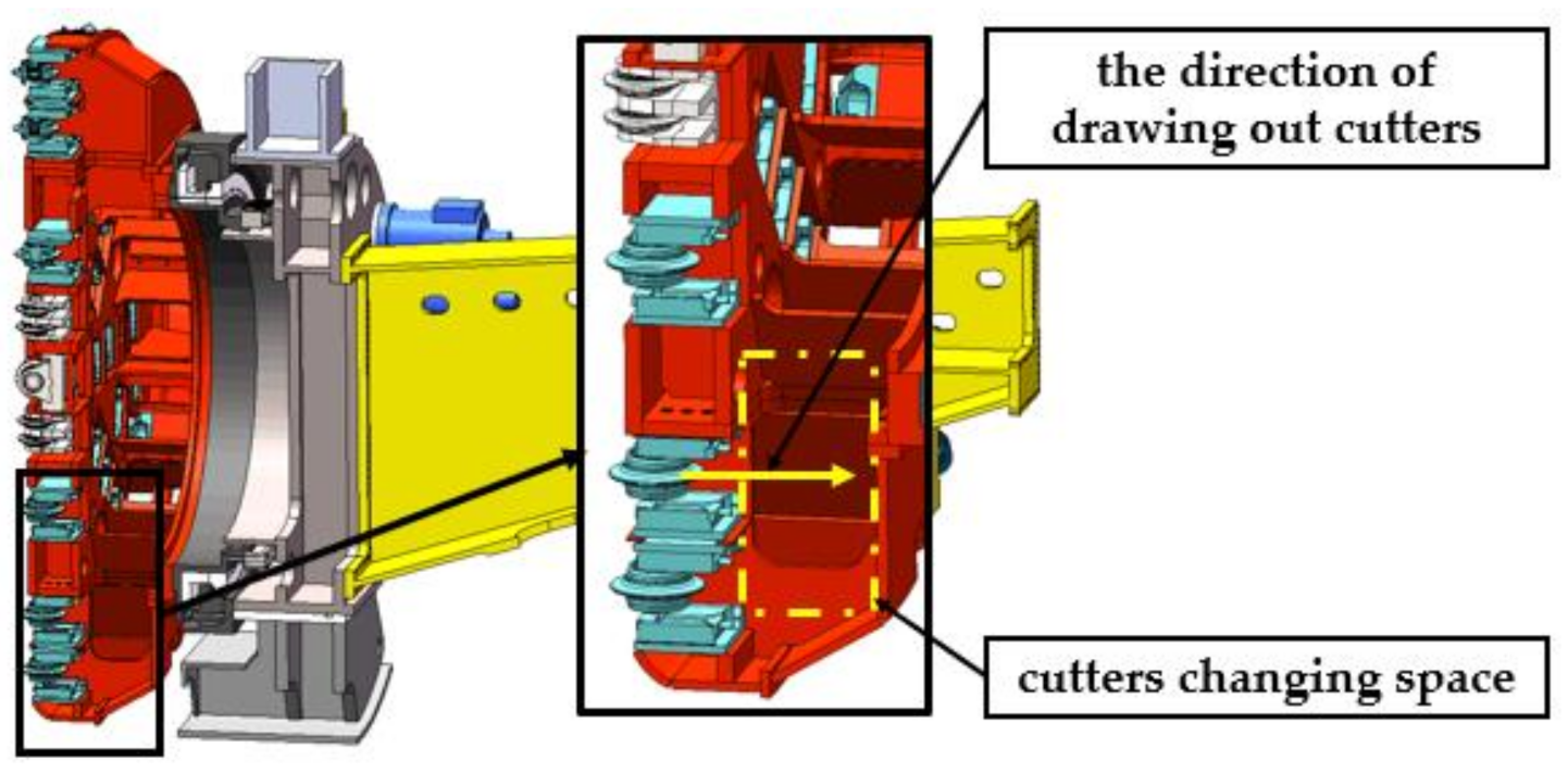
3.1.2. Dimensions for Drawing out Cutters

As shown in Figure 5, the space for cutter change is very narrow, and the dimensions for drawing out cutters is very short in the TBM. Moreover, the space needed to pull out cutters cannot be increased by modifying the structure of the TBM. Therefore, L is a very important index for the ICS, which can be obtained using the measurement function in SolidWorks, which is a 3D modeling software. For solution 1, L is 490 mm.

3.1.3. Overall Dimensions of the ICS

The overall dimension of the ICS is
V = abh,
where a, b, and h are the length, width, and height of the ICS, respectively. The number of cutters on the TBM cutterhead is related to the whole size of the ICS. The more cutters there are, the higher the efficiency of the TBM. Thus, V of the ICS should not exceed that of the TCS to reduce the influence on the efficiency of the TBM. Therefore, V = 472 mm × 600 mm × 620 mm for solution 1.

3.1.4. Static Strength

The ICS should have enough strength to ensure its reliability when the cutters are under a large impact load. Taking solution 1 as an example, the finite element method is used to analyze the stress and deformation of the new ICS that applies nominal loads. The cutter ring will be damaged if the cutter receives a load greater than the nominal load, which is generally used to check the ICS in the project. The normal force, FN, lateral force, FS, and rolling force, FT, of the cutter under the nominal load [20] are 315 kN, 47.25 kN, and 31.5 kN, respectively, and the directions of the forces are shown in Figure 6a.
In this paper, the stress state of the new tool system under a working load is analyzed by the linear elastic finite element method. The material of the TBM ICSs is Q345. Q345 is a low carbon alloy steel with yield strength of 345 MPa. The elastic modulus of Q345 is 206 GPa, and the Poisson’s ratio of Q345 is 0.5. The corresponding international standard ISO 630-3:2012 (Structural steels—Part 3: Technical delivery conditions for fine-grain structural steels) is S355. The mesh model is mixed with tetrahedron and hexahedron elements, and the software used is ANSYS 18.0. The load input is shown in Figure 6a. The finite element analysis results of the ICS are displayed in Figure 6b,c. The analysis results show that the maximum stress and the maximum deformation of the ICS are 96.556 MPa and 0.7399 mm, respectively, under the nominal load. This shows that the safety factor of the ICS under nominal load is 3.58, which is higher than the required safety factor of 2.

3.1.5. Mass of the ICS

The mass of the ICS directly affects the size of the cutter-change robot, but the space available for robot work inside the TBM is very small. Therefore, m is a very important indicator of the performance of the ICS. For this index, the mass of the parts captured by the TBM cutter-change robot is considered, as shown in Figure 7. This article does not consider the mass of the cutter box because it is directly welded to the cutter head. The value of m is 319 kg for solution 1.

3.1.6. Preload Provided by the ICS

The cutters are subjected to great impact forces and vibration, which may cause the ICS to loosen. To prevent this, it is necessary to apply the preload in the structure of the ICS in advance. Thus, P0 is a critical parameter for the performance of the ICS. When the four solutions are locked, the pre-tightening force of the locking block is provided by the bolt. At present, the bolts of the cutter system used in the project are all 10.9 fine-grained bolts, so the bolt grades of the four ICS solutions are uniformly set to 10.9 fine-grained bolts. Two bolts are used in solution1, and the standard preload is 916 kN. After analyzing the evaluation parameters of the four TBM ICSs and the TCS, the results were obtained as shown in Table 3.
To better analyze the influence of various parameters on the evaluation index of the TBM ICS, the parameter values were normalized to obtain the normalized parameter values shown in Table 4.

3.2. Establishment of the Evaluation Indicator of the ICS

The evaluation of the ICS involves multiple factors, which is a complex decision-making problem. The AHP, one kind of multicriteria decision-making method for solving complex decision problems [21], was used in this article to determine the weight of each factor. The basic principles of the AHP for a complex and difficult problem include selecting relevant factors first and ensuring their hierarchical structure, then comparing these factors with each other to ensure their relative importance, and finally determining their weights [22]. For the evaluation of the ICS, the evaluation hierarchy included the target layer, the criterion layer, and the solution layer, as shown in Figure 8.
The discriminant matrix was obtained by comparing the relative importance of each evaluation factor, as shown in Equation (14). This process was discussed and decided by 30 TBM design experts, which has engineering-guidance significance.
A = 1 1 2 3 2 2 3 2 1 5 3 3 5 1 3 1 5 1 1 2 1 2 2 1 2 1 3 2 1 1 2 1 2 1 3 2 1 1 2 1 3 1 5 1 2 1 2 1 2 1
The comparison matrix was checked for consistency after it was constructed. Moreover, the consistency of the comparison matrix has to be validated by means of consistency indicators (CI) and checkout ratio (CR), and they can be calculated by Equations (15) and (16), respectively.
C I = λ max n / n 1 = ( 6.0739 6 ) / 6 1 = 0.0148 ,  
C R = C I R I ( 6 ) = 0.0148 1.24 = 0.0117 ,
where CI is the consistency indicators, λmax is the largest eigenvalue of the comparison matrix, n is the order of the comparison matrix, CR is the checkout ratio, RI(n) is a random consistency index, which is related to n and is standard.
Since,
C R = 0.0117 < 0.1 ,
the comparison matrix passes the consistency test.
Therefore, the eigenvector w corresponding to the largest eigenvalue of the comparison matrix can be used as the weight of these factors.
w = 0.2224 , 0.3792 , 0.0795 , 0.1281 , 0.1281 , 0.0626 T
The TBM ICS evaluation index S is established by Equation (19).
S = w 1 n + w 2 L + w 3 V + w 4 σ + w 5 m + w 6 P 0
where the S values of solutions 1–4 of the ICS are S1 = 0.9481, S2 = 0.7478, S3 = 0.8646, and S4 = 0.8148, respectively. It can be known from the S values that solution 1 is the best, so solution 1 is taken as the final scheme.

4. Design of the Anti-Looseness Structure of the ICS

When the TBM breaks the rock, the overall vibration of the cutter system is extremely harsh, and the cutters will bear a very large alternating load [23]. According to the field measurement, the cutter head vibration of the TBM can reach ±3 g (g represent the acceleration of the gravity) during driving. The main function of the cutter system is to install and lock the cutter [24]. However, under the actions of shock, vibration, and alternating loading, fasteners easily loosen, which leads to increased cutter wear and cutter system damage [25]. Moreover, if the cutter system is loose due to vibration during TBM driving, the hob will fall off, which may lead to TBM damage and even safety accidents. Therefore, the design of the anti-loosening structure of the ICS is critical and necessary. Dynamic performance is indeed an important component of the new tool system. Through the force transfer analysis, the weak link that affects the vibration characteristics of the cutter system is the bolt. The contact stiffness of the cutter system will stay strong only if the bolt does not loosen (or the relaxation is small). The disadvantage is that the anti-loosening performance of the cutter system is not verified under the impact load, which is the focus of the next step.

4.1. Anti-Loosening Principle of the TCS

The TCS mainly uses a double nut structure to prevent loosening, which is a frictional loosening prevention method, that is, to prevent loosening by increasing the friction between the threads [26]. A schematic diagram of the anti-loosening structure of the TCS is shown in Figure 9a. First, the main nut is tightened, the bolt pulls the locking block up to lock the cutter shaft, and then tightens the auxiliary nut to prevent the TCS from loosening.

4.2. Anti-Loosening Principle of the ICS

A schematic diagram of the anti-loosening structure of the novel TBM ICS is shown in Figure 9b. First, the screw is rotated, the nut moves from top to bottom, and the locking block gradually reaches the locking position. When the locking block reaches the locked position, the left and right connecting links are close to the horizontal state. Then, the screw is rotated so that the left and right push-links are exactly horizontally aligned. At this time, the locking block relies on the pressure between the connecting link and the nut to achieve locking. Moreover, the mechanism composed of the locking block, the link, and the nut form a dead point at this time. Regardless of how much the vibration load is transmitted from the cutter to the locking block, theoretically, the nut will not move, which effectively prevents the ICS from loosening.

5. Experimental Verification

To further verify the kinematic performance and anti-loosening performance of the novel TBM ICS, the TBM ICS and the TCS were processed in this paper using a 1:4 scale. The physical drawings of the two scales are shown in Figure 10, where Figure 10a is a scale sample of the TCS and Figure 10b is a scale sample of the TBM ICS. After disassembly and assembly tests, it was found that the mechanism of the new TBM ICS can achieve the purpose of locking the cutter with a simple action. Next, this article will verify the anti-looseness performance of the TBM ICS.

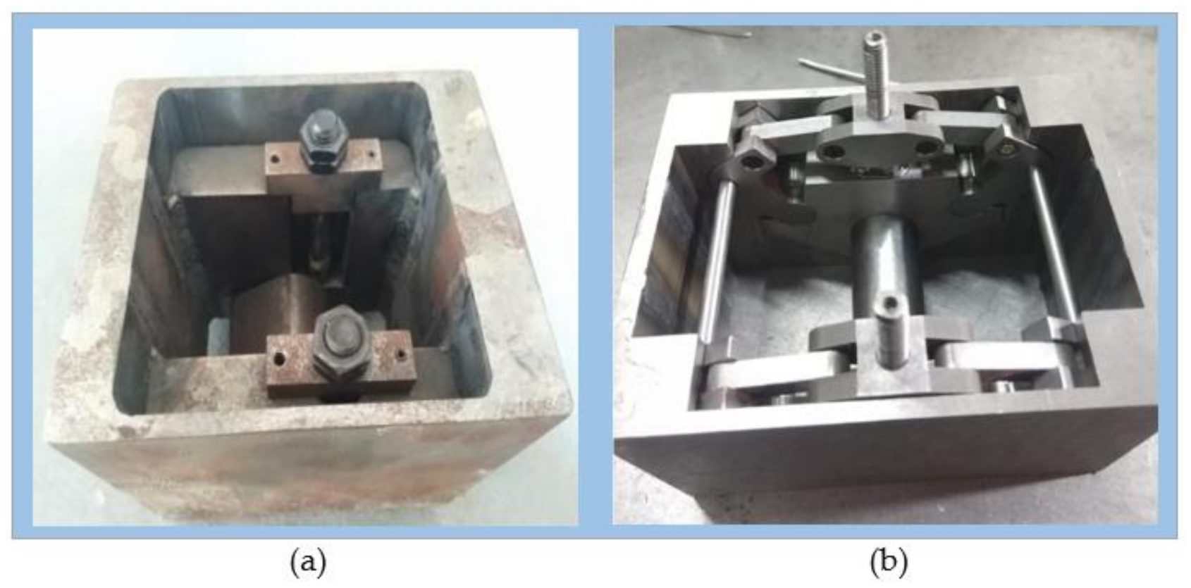
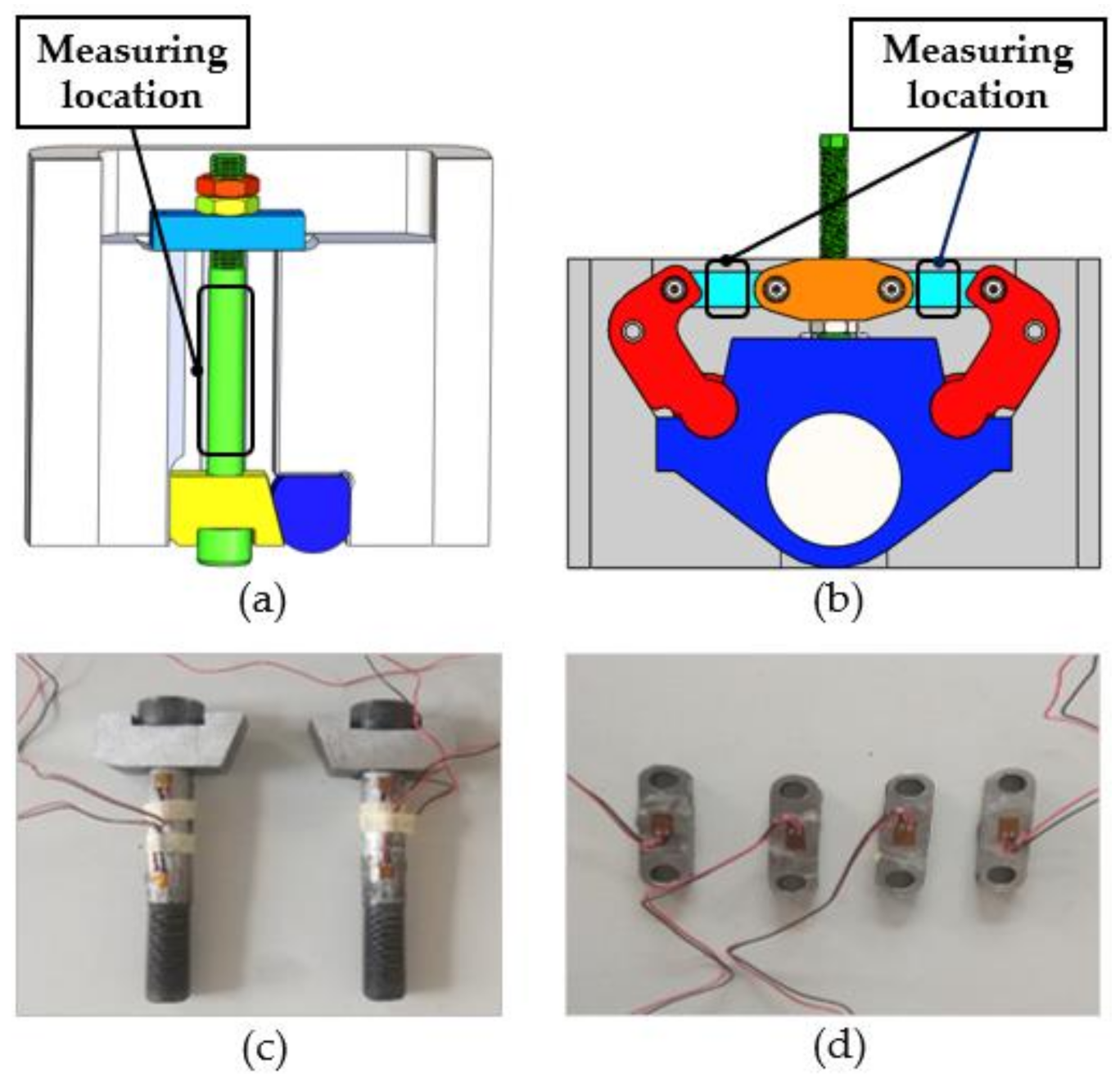
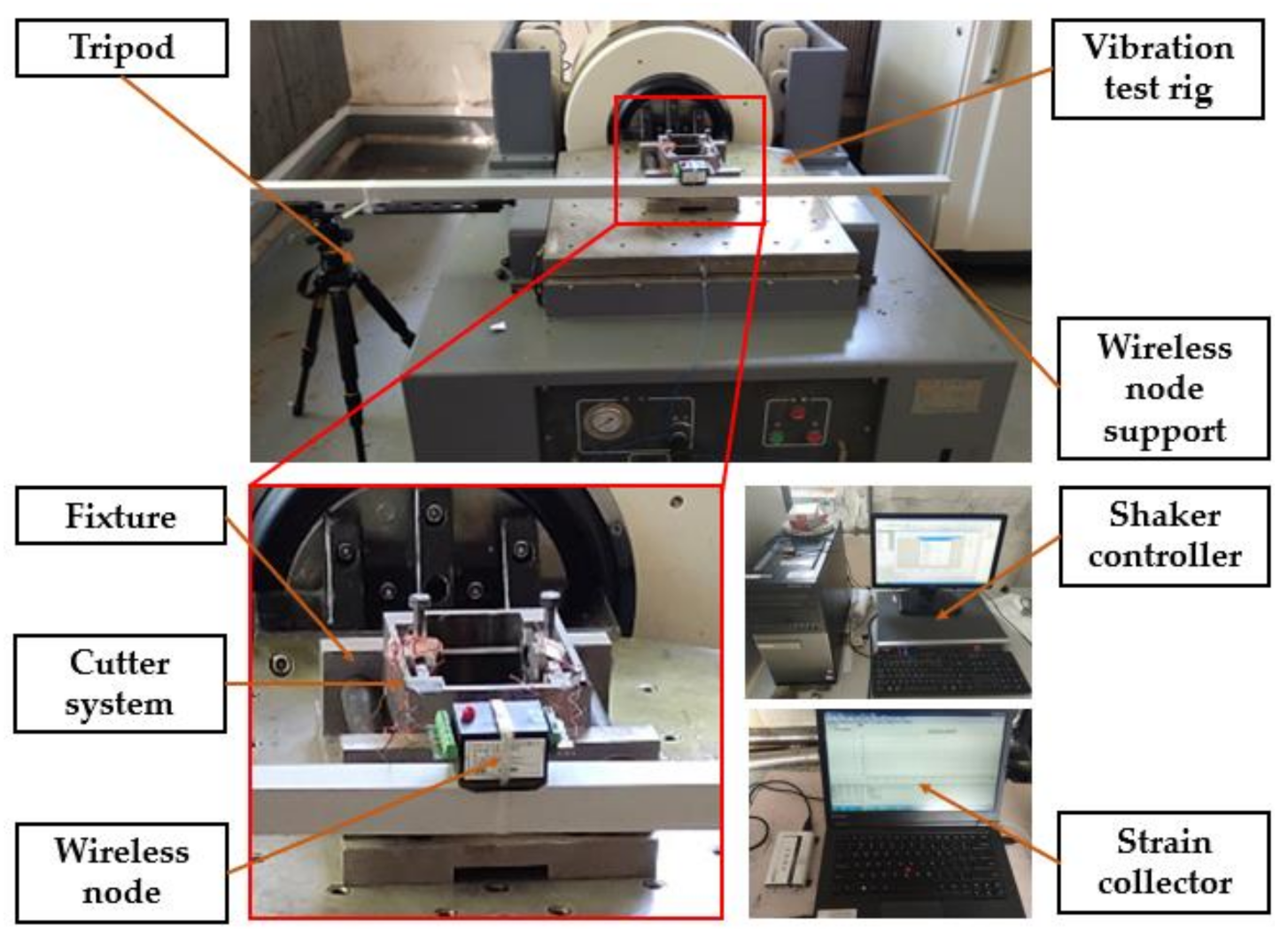
5.1. Experimental Principle

At present, there is no standard experimental method for evaluating the fastening performance of complex structural parts. However, for the TCS and the new TBM ICS, the fastening of the two structures comes from the connection of the screw and the nut. Therefore, the anti-loosening performance of the structure is directly related to the anti-loosening performance of the screw and nut [27]. Currently, the experimental methods of the anti-loosening performance of bolt fasteners are widely studied, mainly including the following three methods: the anchor bolt method [28], the sleeve test method, and the lateral vibration test method [29]. The anchor bolt method has been eliminated due to its long experimental period and unsatisfactory experimental results. Both the sleeve test method and the lateral vibration test method apply a transverse sinusoidal load on the fastener and determine the looseness of the fastener by measuring the pre-tension of the fastener [30]. In the above two kinds of experiments, the smaller the reduction in preload, the better is the anti-loosening performance of the fastener. This paper mainly referred to the evaluation principle of the lateral vibration experiment method and evaluated the anti-loosening performance of the new TBM ICS by measuring the percentage of the preload of the two cutter systems failing at the same time. In the experiment, the two cutter systems were consistent in terms of the scale ratio, processing materials, bolt grades, and loading conditions, which excluded the influence of other factors on the experiment.

5.2. Experimental Program

According to the analysis of the anti-loosening principle of the TCS and the ICS, the preload of the TCS comes from the thread deformation of the bolt and the nut and is transmitted to the cutter shaft through the screw and wedge. The tension of the screw was measured to reflect the preload force of the TCS in this article, as shown in Figure 11a. The preload of the new ICS comes from the compression deformation of the connecting links. As shown in Figure 11b, this paper obtained the preload force of the ICS by measuring the pressure of the connecting links. Since both cutter systems were symmetrical structures, the following measurement methods were used to reduce system errors. For the TCS, two strain gauges were attached to each screw along a coaxial line, and the average value was taken as the strain value of the screw. The new TCS took the average strain of the two connecting links on the same side as the strain value on that side.
To speed up the relaxation process of the overall structure, a vibration block was installed on the cutter shaft, as shown in Figure 12. When the cutter system reciprocated with the vibration table, the vibrating block impacted the cutter shaft due to inertia and generated an alternating load, which promoted the relaxation of the overall structure. To ensure the same size of the alternating load, the mass of the vibrating block of the two schemes was 0.65 kg.
The anti-loosening performance test system of the cutter system is shown in Figure 13. The scale sample of the cutter system was fixed on the vibration table, and the experiments were performed with vibration accelerations of 3 g and 10 g. Moreover, the vibration frequency of both cases was 30 Hz. During the experiment, the strain value was recorded every hour by the strain collector.

5.3. Analysis of the Experimental Results

This paper normalizes the preload force with Equation (20) for a better comparison due to the difference in the initial preload force of the two cutter systems.
η = F t F 0 ,
where Ft is the preload at time t and F0 is the preload at the initial time. The preload can be obtained by Equations (21) and (22):
σ = E ε
F = σ S
where ε is the strain value, E is the elastic modulus of the material, S is the sectional area of the tested part, and F is the axial force of the tested part.
The change in the ƞ values of the two cutter systems under two experimental conditions is shown in Figure 14 and Table 5.
As seen from Figure 14 and Table 5:
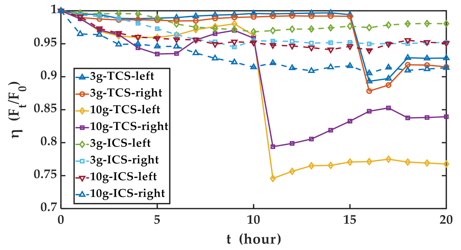
  • Under the experimental condition of 3 g, the changes in the preload on the left and right sides of the two cutter systems were synchronous. After basically remaining stable during the first 15 h, the preload of the TCS suddenly dropped sharply at the 15th hour before rising slightly to reach stability. At the end of the 20th hour, the preload on the left and right sides of the TCS decreased by 7.18% and 8.51%, respectively. The preload of the TBM ICS slowly decreased between 0–10 h, and then it was stable in the following 10 h. Finally, at the 20th hour, the pretension on the left and right sides of the ICS decreased by 1.96% and 4.82%, respectively.
  • In the 10 g experimental condition, the changes in the pretension of the left and right sides of the two cutter systems were also synchronous. After slowly decreasing in the first 6 h, the preload of the TCS increased slightly in the following 4 h, then plummeted at the 10th hour. Then, it climbed gradually to reach stability. Finally, the pretension force on the left side decreased by 23.25%, and that on the right side decreased by 16.07%. After falling mildly between 0–10 h, the preload of the TBM ICS reached a substantially stable state in the following 10 h. In the end, the pretension force on the left side decreased by 4.92%, and that on the right side decreased by 8.64%.
From the above analysis, it can be seen that under the two experimental conditions of 3 g and 10 g, the preload force of the novel TBM ICS decreased less than that of the TCS at the same time, which illustrates that the anti-loosening performance of the novel TBM ICS was better than that of the TCS. This is because when the inertial force generated by the transverse vibration acts directly on the screw of the TCS, the relative movement of the screw and the nut is increased, resulting in the rapid decline of the fastening mechanism of the TCS within a certain time. As a result, in the field construction, the tightening degree of the TCS needs to be repaired within 8 h. For the ICS, the locking block and link are symmetrically arranged, and the force of the connecting rods on the nut on both sides will cancel each other, and the reduced screw and nut move each other. According to the experimental data, the preload of the ICS did not decrease rapidly in 20 h. In the future, the maintenance frequency can be reduced after engineering application.
At the same time, we notice that the preload increased at a certain time. This was due to the sinusoidal vibration of the tool holder in the experiment, and the strain value of the test part was in fluctuation. The sampling frequency of this experiment was small, so the preload increased. There is a similar phenomenon in reference [30].
This experimental method provides a test idea and data processing (normalization) method for the anti-loosening performance of the ICS (or even other fastening mechanisms), although this processing method has been applied in other fields.

6. Conclusions

In this paper, to solve the problem that the TCS is not applicable to the TBM automatic tool change system, a novel ICS that can meet the requirements of TBM automatic tool change was developed. This paper mainly solved the following three problems concerning the development of the TBM ICS.
  • The development of the existing TBM ICSs relies too much on the engineering experience of the designer. The design scheme is relatively simple, and the contrast is not strong. The topological structure theory of planar mechanisms was applied for the first time to the design of a new TBM ICS in this paper.
  • To evaluate the performance of TBM ICSs to obtain the optimal design, this paper established a TBM ICS evaluation index based on the AHP. The evaluation method considers six factors that affect the performance of the TBM ICS, including the number of disassembly actions, dimensions of the drawing out cutters, overall dimensions, static strength, mass, and preload. By evaluating the four ICSs proposed, an ICS with the best performance was selected.
  • To improve the anti-loosening performance of the ICS, this article proposed a dead-point anti-loosening structure for the ICS and conducted related experimental research. The experimental results show that after a 20 h vibration experiment, the preload reduction of the TCS was 1.76 times and 2.69 times that of the ICS under the experimental conditions of 3 g and 10 g, respectively. That is, under the same vibration conditions, the ICS had better anti-loosening performance than did the TCS.
The limitation of this study was that the dynamic performance of the new structure was not analyzed, which is the focus of future research.

Author Contributions

Conceptualization, Z.M. and D.Y.; methodology, Z.M. and D.Y.; software, Y.B.; formal analysis, P.Z.; investigation, P.Z. and J.H.; resources, P.Z. and J.H.; data curation, Y.B.; writing—original draft preparation, D.Y. and Z.M.; writing—review and editing, D.Y. and Z.M.; supervision, J.H.; project administration, P.Z.; funding acquisition, J.H. All authors have read and agreed to the published version of the manuscript.

Funding

This research was funded by “the National Key R & D Plan of China” (grant number 2018YFB1306701), “the National Natural Science Foundation of China” (grant number 51875076), and “the NSFC-Liaoning United Key Fund” (grant number U1708255).

Institutional Review Board Statement

Not applicable.

Informed Consent Statement

Not applicable.

Data Availability Statement

Not applicable.

Conflicts of Interest

The authors declare no conflict of interest.

References

  1. Armaghani, D.J.; Koopialipoor, M.; Marto, A.; Yagiz, S. Application of several optimization techniques for estimating TBM advance rate in granitic rocks. J. Rock Mech. Geotech. Eng. 2019, 11, 779–789. [Google Scholar] [CrossRef]
  2. Delisio, A.; Zhao, J. A new model for TBM performance prediction in blocky rock conditions. Tunn. Undergr. Space Technol. 2014, 43, 440–452. [Google Scholar] [CrossRef]
  3. Wang, L.H.; Kang, Y.L.; Zhao, X.J.; Zhang, Q. Disc cutter wear prediction for a hard rock TBM cutterhead based on energy analysis. Tunn. Undergr. Space Technol. 2015, 50, 324–333. [Google Scholar] [CrossRef]
  4. Ren, D.J.; Shen, S.L.; Arulrajah, A.; Cheng, W.C. Prediction Model of TBM Disc Cutter Wear during Tunnelling in Heterogeneous Ground. Rock Mech. Rock Eng. 2018, 51, 3599–3611. [Google Scholar] [CrossRef]
  5. Hassanpour, J.; Rostami, J.; Azali, S.T.; Zhao, J. Introduction of an empirical TBM cutter wear prediction model for pyroclastic and mafic igneous rocks; a case history of Karaj water conveyance tunnel, Iran. Tunn. Undergr. Space Technol. 2014, 43, 222–231. [Google Scholar] [CrossRef]
  6. Liu, Q.S.; Liu, J.P.; Pan, Y.C.; Zhang, X.P.; Peng, X.X.; Gong, Q.M.; Du, L.J. A Wear Rule and Cutter Life Prediction Model of a 20-in. TBM Cutter for Granite: A Case Study of a Water Conveyance Tunnel in China. Rock Mech. Rock Eng. 2017, 50, 1303–1320. [Google Scholar] [CrossRef]
  7. Copur, H.; Cinar, M.; Okten, G.; Bilgin, N. A case study on the methane explosion in the excavation chamber of an EPB-TBM and lessons learnt including some recent accidents. Tunn. Undergr. Space Technol. 2012, 27, 159–167. [Google Scholar] [CrossRef]
  8. Su, F.; Wang, W.; Huo, J.; Li, Z. Optimal layout design of cutters on tunnel boring machine. J. Northeast. Univ. (Nat. Sci.) 2010, 31, 877–881. [Google Scholar]
  9. Gallo, J.; Perez-Acebo, H. Performance model for Micro Tunnelling Boring Machines (MTBM). Inf. Constr. 2017, 69, e203. [Google Scholar] [CrossRef] [Green Version]
  10. Hegab, M.Y.; Smith, G.R. Delay time analysis in microtunneling projects. J. Constr. Eng. Manag. ASCE 2007, 133, 191–195. [Google Scholar] [CrossRef]
  11. Jianjun, Y.; Renming, G.; Du, J. Design and implementation of disc cutter changing robot for tunnel boring machine (TBM). In Proceedings of the 2019 IEEE International Conference on Robotics and Biomimetics (ROBIO), Dali, China, 6–8 December 2019; pp. 2402–2407. [Google Scholar]
  12. Moubarak, S. Maintenance Robotics in TBM Tunnelling. In Proceedings of the 32nd International Symposium on Automation and Robotics in Construction and Mining (ISARC 2015), Oulu, Finland, 15–18 June 2015; International Association for Automation and Robotics in Construction (IAARC): London, UK, 2015; pp. 1–8. [Google Scholar]
  13. Chen, G. Design and Test of Intelligent Inspection and Replacement System of TBM Excavation Tools. In Proceedings of the 2019 International Conference on Virtual Reality and Intelligent Systems, Jishou, China, 14–15 September 2019; IEEE: Piscataway, NJ, USA, 2019; pp. 219–222, ISBN 978-1-7281-5050-5. [Google Scholar]
  14. Simi, A.; Manacorda, G. The NeTTUN Project: Design of a GPR Antenna for a TBM. In Proceedings of the 2016 16th International Conference on Ground Penetrating Radar, Hong Kong, China, 13–16 June 2016; IEEE: Piscataway, NJ, USA, 2016; pp. 1–6, ISBN 978-1-5090-5181-6. [Google Scholar]
  15. Bogue, R. Snake robots A review of research, products and applications. Ind. Robot 2014, 41, 253–258. [Google Scholar] [CrossRef]
  16. David, O.; Russotto, F.X.; Simoes, M.D.; Measson, Y. Collision avoidance, virtual guides and advanced supervisory control teleoperation techniques for high-tech construction: Framework design. Autom. Constr. 2014, 44, 63–72. [Google Scholar] [CrossRef]
  17. Rubrecht, S.; Singla, E.; Padois, V.; Bidaud, P.; de Broissia, M. Evolutionary Design of a Robotic Manipulator for a Highly Constrained Environment. In New Horizons in Evolutionary Robotics: Extended Contributions from the 2009 Evoderob Workshop; Doncieux, S., Bredeche, N., Mouret, J.B., Eds.; Springer Science & Business Media: Berlin, Germany, 2011; pp. 109–121. ISBN 978-3-642-18271-6. [Google Scholar]
  18. Satoh, J.; Hanaoka, Y.; Okada, T. Development of cutter bit replacement system. Hitachi Zosen Tech. Rev. 2008, 68, 26–35. [Google Scholar]
  19. Chao, Y. Design and experimental verification of motion mechanism for automatic laser welding robot. Electr. Weld. Mach. 2014, 44, 69–71, 75. [Google Scholar] [CrossRef]
  20. Huo, J.Z.; Xu, Z.H.; Meng, Z.C.; Li, J.B.; Dong, J.H.; Wang, L.P. Coupled modeling and dynamic characteristics of TBM cutterhead system under uncertain factors. Mech. Syst. Signal Proc. 2020, 140, 106664. [Google Scholar] [CrossRef]
  21. Cay, T.; Uyan, M. Evaluation of reallocation criteria in land consolidation studies using the Analytic Hierarchy Process (AHP). Land Use Pol. 2013, 30, 541–548. [Google Scholar] [CrossRef]
  22. Ouma, Y.O.; Tateishi, R. Urban Flood Vulnerability and Risk Mapping Using Integrated Multi-Parametric AHP and GIS: Methodological Overview and Case Study Assessment. Water 2014, 6, 1515–1545. [Google Scholar] [CrossRef]
  23. Huo, J.; Yang, J.; Sun, W.; Zhang, X. Structure design and static/dynamic analysis of TBM cutterhead supporting ribs. J. Harbin Eng. Univ. 2014, 35, 883–888. [Google Scholar]
  24. Huo, J.Z.; Wu, H.Y.; Yang, J.; Sun, W.; Li, G.Q.; Sun, X.L. Multi-directional coupling dynamic characteristics analysis of TBM cutterhead system based on tunnelling field test. J. Mech. Sci. Technol. 2015, 29, 3043–3058. [Google Scholar] [CrossRef]
  25. Zhang, J.; Du, M.; Shao, Y.; Chen, J. Simulation on Loosening Behavior of Threaded Fastener under Transverse Vibration. In Proceedings of the 2015 IEEE International Conference on Mechatronics and Automation, Beijing, China, 2–5 August 2015; IEEE: Piscataway, NJ, USA, 2015; pp. 1886–1890, ISBN 978-1-4799-7098-8. [Google Scholar]
  26. Panja, B.; Das, S. Development of an anti-loosening fastener and comparing its performance with different other threaded fasteners. Sadhana Acad. Proc. Eng. Sci. 2017, 42, 1793–1801. [Google Scholar] [CrossRef]
  27. Yang, G.; Xie, J.; Xie, Y. Study on mechanism of anti-loosening of a new type of nut based on fem. Eng. Mech. 2010, 27, 224–228. [Google Scholar]
  28. Jing, X.; Pan, F.; Shen, Z. Development of transverse vibration test-bed for fasteners. J. Mach. Design 2005, 22, 59–61. [Google Scholar]
  29. Liu, C.; Sun, J.; Mo, Y. A study of effects on anti-loosening performance of threaded fasteners. Mod. Manuf. Eng. 2018, 451, 138. [Google Scholar]
  30. Bhattacharya, A.; Sen, A.; Das, S. An investigation on the anti-loosening characteristics of threaded fasteners under vibratory conditions. Mech. Mach. Theory 2010, 45, 1215–1225. [Google Scholar] [CrossRef]
Figure 1. Layout of the disc cutter in a tunnel boring machine (TBM).
Applsci 11 00644 g001
Figure 2. Structure diagram of the traditional cutter system (TCS).
Applsci 11 00644 g002
Figure 3. (a) Topological diagram; (b) Weighted topology diagram.
Applsci 11 00644 g003
Figure 4. Schematic diagram of removing cutters.
Applsci 11 00644 g004
Figure 5. Schematic diagram of the TBM cutter change space and drawing direction.
Applsci 11 00644 g005
Figure 6. Static stress analysis. (a) Schematic diagram of the force directions; (b) The maximum stress of finite element analysis of the ICS; (c) The maximum deformation of the ICS.
Applsci 11 00644 g006
Figure 7. Schematic diagram of the parts grasped by the TBM cutter-change robot.
Applsci 11 00644 g007
Figure 8. Evaluation hierarchy diagram of the evaluation of the ICS.
Applsci 11 00644 g008
Figure 9. (a) Schematic diagram of the anti-loosening structure of the TCS; (b) Schematic diagram of the anti-looseness structure of the novel TBM ICS.
Applsci 11 00644 g009
Figure 10. Scale sample. (a) The TCS; (b) The novel TBM ICS.
Applsci 11 00644 g010
Figure 11. Strain measurement. (a) Measuring location of the TCS; (b) Measuring location of the ICS; (c) Measuring location of the TCS scale sample; (d) Measuring location of the ICS scale sample.
Applsci 11 00644 g011
Figure 12. Schematic diagram of the vibration block position.
Applsci 11 00644 g012
Figure 13. Pictures of the anti-loosening performance test system of the cutter system.
Applsci 11 00644 g013
Figure 14. The value change of ƞ for two types of cutter systems under two kinds of working conditions.
Applsci 11 00644 g014
Table 1. Relation table between the schematic diagram of the integrated cutter system (ICS) mechanism and the motion chain diagram.
The Motion Chain DiagramThe Schematic Diagram of the ICS Mechanism
Bar 1 as the ICS FrameBar 2 as the ICS Frame
Locking Block PositionLocking Block Position
Applsci 11 00644 i001Bars 5 and 6 Applsci 11 00644 i002Bars 3 and 4The mechanism with bar 1 is the same as the frame, and bars 5 and 6 are the same as the locking block
Applsci 11 00644 i003Bars 5 and 6 Applsci 11 00644 i004Bars 3 and 4 Applsci 11 00644 i005
Applsci 11 00644 i006Bars 5 and 6 Applsci 11 00644 i007Bars 3 and 4The mechanism with bar 1 is the same as the frame, and bars 5 and 6 are the same as the locking block
Applsci 11 00644 i008Bars 5 and 6: it is equivalent to a 4-bar mechanism
Applsci 11 00644 i009Bars 5 and 6: it is equivalent to a 4-bar mechanism
Table 2. Four ICS solutions.
SolutionSchematic DiagramStructure Diagram3D Axonometric Diagram
Solution 1 Applsci 11 00644 i010 Applsci 11 00644 i011 Applsci 11 00644 i012
Solution 2 Applsci 11 00644 i013 Applsci 11 00644 i014 Applsci 11 00644 i015
Solution 3 Applsci 11 00644 i016 Applsci 11 00644 i017 Applsci 11 00644 i018
Solution 4 Applsci 11 00644 i019 Applsci 11 00644 i020 Applsci 11 00644 i021
Table 3. Evaluation parameter values of the four TBM ICSs and the TCS.
SolutionsnL/mmV/mm3σ/MPaM/kgP0/kN
TCS9650606×530×65095.37197916
Solution 13490472×600×62095.56319916
Solution 23690390×600×720347.42318916
Solution 33520563×624×635114.40445916
Solution 43546584×624×648168.37432916
Table 4. Normalized parameter values of four TBM ICSs and the TCS.
SolutionsnLVσmP0
TCS0.330.750.811.001.001.00
Solution 11.001.000.961.000.621.00
Solution 21.000.711.000.270.621.00
Solution 31.000.940.760.830.441.00
Solution 41.000.900.710.570.461.00
Table 5. Decrease ranges of the bolt preloads of the ICSs and the TCS.
AccelerationCutter TypeDecrease Range of Left Bolt PreloadDecrease Range of Right Bolt Preload
3 gTCS7.18%8.51%
ICS1.96%4.82%
10 gTCS23.25%16.07%
ICS4.92%8.64%
Publisher’s Note: MDPI stays neutral with regard to jurisdictional claims in published maps and institutional affiliations.

