Article

Carbon Nanotube Film/Silicon Heterojunction Photodetector for New Cutting-Edge Technological Devices

by
Mattia Scagliotti
1,2,
Matteo Salvato
1,2,
Federico Frezza
1,
Daniele Catone
3,
Lorenzo Di Mario
3,4,
Maurizio Boscardin
5,
Maurizio De Crescenzi
1,2 and
Paola Castrucci
1,2,*
1
Dipartimento di Fisica, Università di Roma “Tor Vergata”, 00133 Roma, Italy
2
Istituto Nazionale di Fisica Nucleare (INFN), Università di Roma “Tor Vergata”, 00133 Roma, Italy
3
Istituto di Struttura della Materia-CNR (ISM-CNR), Division of Ultrafast Processes in Materials (FLASHit), 00133 Rome, Italy
4
Zernike Institute for Advanced Materials, University of Groningen, Nijenborgh 4, 9747 AG Groningen, The Netherlands
5
Micro-Nano Characterization Facility, Fondazione Bruno Kessler (FBK), 38123 Trento, Italy
*
Author to whom correspondence should be addressed.
Appl. Sci. 2021, 11(2), 606; https://doi.org/10.3390/app11020606
Submission received: 16 December 2020 / Revised: 4 January 2021 / Accepted: 8 January 2021 / Published: 10 January 2021
(This article belongs to the Special Issue Advances in Transparent, Conductive Carbon Nanotube Films)

Abstract

:

Featured Application

Photodetectors based on carbon nanotube/n-silicon heterojunction can be applied in all the technology fields where a spectral range from near ultraviolet to near infrared and a response time of a few nanoseconds are necessary.

Abstract

Photodetector (PD) devices based on carbon nanotube/n-silicon heterojunction (NSH) have been realized, with a linear response in a large optical power range, proving competitive performances with respect to a recent nanostructure-based detector and those currently available on the market. The core of these devices is a thin semi-transparent and conductive single-walled carbon nanotubes film with a multitask role: junction element, light absorber and transmitter, photocarrier transporting layer, and charge collector. The PD exhibits rise times of some nanoseconds, detecting light from ultraviolet (240 nm) to infrared (1600 nm), and external quantum efficiency reaching 300% in the VIS spectra region.

1. Introduction

The extraordinary properties of carbon nanotubes (CNTs) have attracted a lot of research producing countless theoretical and experimental investigations and a large number of potential applications. One of the most significant properties of CNTs is their one-dimensional electronic structure depending on the nanotube number of walls and wall helicity [1]. In particular, helicity is at the origin of the single wall carbon nanotube (SWCNT) semiconducting or metallic behavior [1]. Theoretically, individual ideal nanotubes exhibit a high electrical current carrying capacity (∝109 A/cm2) and a ballistic electron transport [2,3,4]. However, many applications of CNTs in real devices have been reported to deal with CNT random network films [5]. In this case, the myriad of CNT-CNT junctions formed in the network, as well as the high number of defects of real CNTs make the charge mobility and transport mechanism in the film different from that of the individual nanotube [6,7,8]. This makes the thickness of the CNT film a key parameter. Indeed, the optical, electrical, and transport properties of the film depend on its thickness [7,8,9]. The lower the film thickness, the higher its optical transparency and sheet resistance. All this highlights the CNT network optical transparency and its conductance strong competition, thus calling for research on the best thickness compromise in the various applications. Among the interesting properties of the CNT films, it is worth citing its flexibility due its inherent network nature and the ease to be integrated into existing semiconductor device technologies. Moreover, they are easily scalable and form rectifying heterojunctions with semiconductors. In this scenario, the CNT film/Si heterojunction is particularly interesting because of the prevalent use of Si in electronics. Many works reported studies devoted to understanding the properties of the CNT/Si heterojunction and to governing its fabrication process [10,11]. In this respect, two challenges are still under debate: how (i) to model the SWCNT/Si heterojunction (NSH); (ii) how to establish an intimate CNT/Si contact by avoiding or reducing chemical-structural modifications to the semiconductor. In addition, a large number of papers reported the possibility to suitably dope the SWCNT film to improve the NSH performances [12,13]. CNT/Si heterojunctions have been investigated for photovoltaic cells [10,11], chemical sensors [14], and photodetectors (PDs) [15,16,17,18,19,20,21,22,23,24]. Particularly interesting are the benefits that NSHs offer with respect to the Si p-n PDs currently dominating the market: e.g., a spectral operating range extending from near ultraviolet (UV) to near infrared (NIR), dimensions that can be reduced, low bias voltages to obtain high sensitivity, and fast response times [19,20,21,22]. At the same time, NSHs, differently from other new interesting materials, promise to largely exploit the large-scale manufacturing processes already in use for Si PDs, thus reducing the economical efforts for the technological transfer.
In this paper, we show the main results of our work about the realization and characterization of photodetectors based on the heterojunction between ultra-thin SWCNT film and n-doped silicon and the progresses made towards an improvement in the intimate contact between SWCNT network and Si substrate. Our devices operate in photovoltaic and photoconductive mode using a three-terminal structure and they adapt well to different types of light sources both continuous and pulsed in a large range of power and energy.

2. Materials and Methods

2.1. SWCNT Film Fabrication

The first fundamental step in the realization of a thin film based on CNTs [7] involves their dispersion in a liquid medium. In our procedure, we used sodium-dodecyl-sulphate (SDS) produced by Sigma-Aldrich, St. Louis, NO, USA (assay > 98.5%) as the anionic surfactant [25], preparing a solution of distilled water with SDS, within which highly pure CoMoCAT single walled carbon nanotubes (Sigma-Aldrich, assay > 90%, with a diameter of 0.7–0.9 nm and composition 10% metallic and 90% semiconductor) powder was inserted with a concentration of 26 µg/mL. The dispersion was tip ultrasonicated (Branson, St. Louis, MO, USA, S250A, 200 W, 20% power, 20 kHz) in an ice-bath for one hour. During this process, the SDS molecules were arranged around the nanotubes, separating them from one another and keeping them dispersed in water. The result was a well-dispersed suspension which is stable for several months without the formation and the precipitation of CNT aggregations. The next step of the SWCNT film realization is a low vacuum filtration process [8]. Different volume aliquots of the dispersion were introduced into a filtration system, composed in the lower part of a porous septum upon which a mixed cellulose ester filter was placed (Pall GN6, 1 inch in diameter and with 0.45 µm pore diameter). Distilled water and a conceived solution of ethanol, methanol, and water were used to rinse the cellulose filter after the deposition of SWCNTs to remove SDS molecules. At the end of the process, homogeneous and stable filters were obtained, and the CNT film was deposited onto a solid substrate.

2.2. SWCNT Film Transfer onto a Substrate

We successfully achieved the easily controlled placement of SWCNT films by dry-transfer printing. This deposition technique we used consists in soaking the SWCNT film on a cellulose filter with ethanol or water, to improve its adhesion and placing it on the substrate. Effectively, the drop casting of the SWCNT films with ethanol and water is important, as they evaporate from the SWCNT network surface, the surface tension of the ethanol compresses the SWCNT network in the out-of-plane direction. After a few minutes, the dried cellulose filter is removed by peeling it, leaving the SWCNT film adhered to the substrate.

2.3. SWCNT Film Optoelectronic Properties Characterization and Control

Optical spectroscopy with unpolarized light was performed on SWCNT films deposited on a glass side, in the UV-visible (VIS)-NIR range, to characterize the optical properties of several SWCNT films. In Figure 1a, the optical transmittance (T) as a function of the incident light wavelength, λ, is shown. The optical transmittance is dominated by the valley centered at about 283 nm due to the light absorption phenomenon of surface plasmon resonance, which is typical of carbon-based thin films and nanostructures [26]. In the spectrum, it is also possible to identify the S33 (300–400 nm), the M11 (400–550 nm), the S22 (550–900 nm), and the S11 (800–1600 nm) electronic transitions between van Hove singularities due to the 90% of semiconducting (Sii) and 10% of metallic (Mii) multi-chiral SWCNT mixture [7]. In Figure 1b, the measured T value of SWCNT films at fixed incident wavelength λ = 550 nm vs their sheet resistance (RS) is reported. Thinner films have higher transmittance and are characterized by higher RS. The variation of the transmittance of CNT films with their sheet resistance (RS) follows the relation
T ( λ ) = ( 1 + Z 0 σ a c ( λ ) 2 R s σ d c ) 2
where Z0 = 377 Ω is the free space impedance, λ is the photon wavelength, and σac and σdc are the optical and electrical conductivity, respectively. The red curve in Figure 1a, has been obtained by fitting the Equation (1) where the only free parameter is the ratio σac/σdc. The fit returned a value for such an optical and electrical conductance ratio equal to 1.2 ± 0.1. The relationship in Equation (1) evidences that T and RS are in strong competition in PD devices: for high RS, the charge collection is limited, while low RS means that a minor number of photons can reach the NSH junction. For this reason, the film realization process is significant because by only controlling the SWCNT dispersion volume used in the filtration process, the optical and electrical properties can be modulated, depending on the film thickness. In the following, SWCNT films with a thickness ranging between 10 and 60 nm were used and a comparison of their performances in the NSH-based PD reported [27].

2.4. Fabrication of the NSH PD

Appositely designed substrates, fabricated by Fondazione Bruno Kessler [28], were employed to obtain the NHS PD. They consist of a crystalline (100) n-doped Si region (150 μm thick, electrical resistivity ρSi = 0.53 Ω cm, number of doping atoms ND = 1016 cm−3) with an Ohmic Au/Cr contact on the back and two Cr/Pt interdigitated (not connected) electrodes on the top. These metal contacts were deposited on a SiO2 template layer to result electrically isolated from the Si substrate, and they are conceived with a multifinger geometry consisting of 50 μm wide Pt/Cr combs. Three configurations of interdigitated top contacts were investigated, each different from the other in the number of fingers N, the distance d between them (N = 3, d = 950 μm; N = 6, d = 450 μm; N = 10, d = 250 μm), and consequently, the active area region formed by the NSH (0.087 cm2, 0.084 cm2, 0.079 cm2, respectively). These multifinger electrode geometries were specifically designed to enhance the charge collection by the external circuit.
The last step for the manufacture of the device involves the deposition of the SWCNT film, through the dry transfer printing method described above, in the upper part of the substrate so that it adheres to the n-doped Si region and to the Pt/Cr interdigitated electrodes. An etching with hydrofluoric acid was performed before the SWCNT film transfer to remove native oxide on the Si surface. Therefore, this top-down type of realization scheme provides a PD which has three external controls that are the gate electrode (G), forming an Ohmic contact with Si, and the multi-finger source (S) and drain (D) electrodes in contact with the SWCNT film. A scheme of the devices is reported in Figure 1c.
The present devices have two operating configurations that can be exploited in light detection: photovoltaic (PV) and the photoconductive (PC) modes. In the former, the photogenerated charges, crossing the NSH, are collected by the bottom and the top electrodes (i.e., G and the short-circuited S and D contacts). In the latter, charges travel across the SWCNT film and are collected by the S and D electrodes.

2.5. Set-Up for Experimental Characterization of SWCNT Film and NSH PD

The current as a function of voltage, (I–V) measurements were acquired using a Keithley 2602A source/meter directly connected to the PD electrodes with coaxial cables through a special reading card, realized and purposely printed for the NSH PDs, which allows the insertion of the sample inside it. All the external controls are adapted to 50 Ω without the use of any filter or amplifier.
The external quantum efficiency (EQE) signal was acquired by an Ametek (Berwyn, PA, USA) 7265 lock-in amplifier upon the device active area illumination through a monochromatic light modulated by a Thorlabs (Newton, NJ, USA) MC 1000A optical chopper system (operating modulation frequency 22 Hz). The incident radiation is obtained by using a monochromator (LOT (Darmstadt, Germany) MSH-300, wavelength range 300–1000 nm) after a LOT LSE 140 Xenon lamp.
The optical spectroscopy measurements were carried out using a Perkin–Elmer Lambda 19 spectrophotometer with unpolarized light acquiring the transmitted optical signal from 200 to 3000 nm. The sheet resistance was measured through the van der Pauw method recording the typical I–V curves in the four-contact geometry.
For fast switching signal acquisition, a 30 GHz Tektronix oscilloscope directly connected with the device reading card was used without any support electronics. The light sources used to illuminate the sample in the measurements shown are manifold: a LOT-Oriel solar simulator AM 1.5 G spectral illumination of 100 mWcm−2 (1 sun), a light emitter diode (LED Kingbright L-7113QBC-D, emission spectrum peaked at λ = 460 nm) and a ultra-fast laser system consisting of a regenerative amplifier, seeded by a Ti:Sa oscillator, coupled with an Optical Parameter Amplifier (OPA) which produces a 35 femtoseconds laser pulse at 1 kHz of repetition rate and in a wavelength range that goes from 240 nm to 20 μm [29,30].

3. Results

3.1. Photovoltaic Configuration

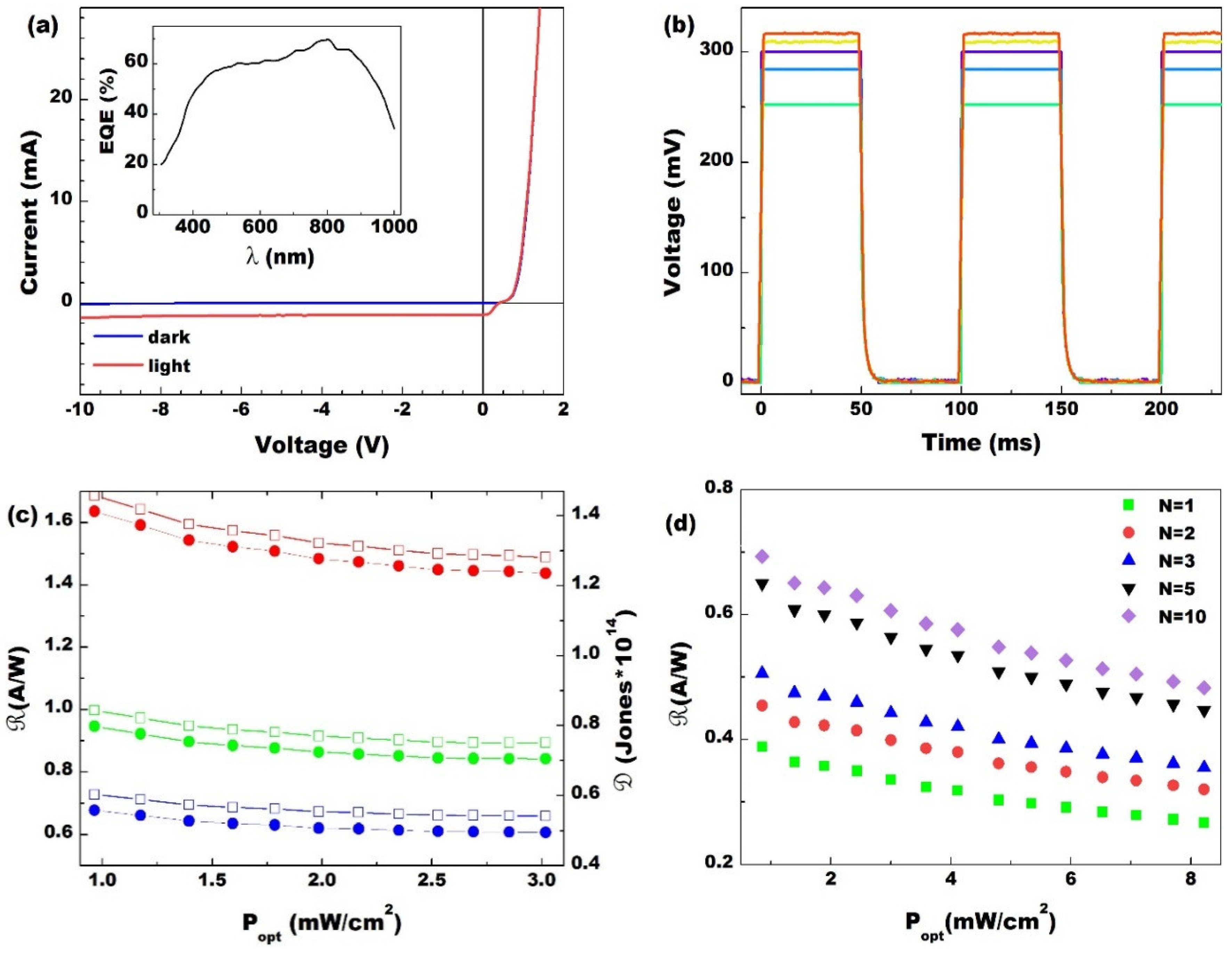
In PV mode, the PD operates as a two-terminal device: an electric current passing through the junction is measured. The typical device I–V characteristic in dark conditions is reported in Figure 2a as a blue line which establishes the rectifying properties of the NSH heterojunction. Lighting the junction with 100 mW/cm2 white light (Figure 2a, red curve), a downshift of the curve in reverse polarization (V ≤ 0) is shown due to the photocurrent generation. This downshift highlights the potentialities of this device for PD applications. A typical NSH PD external quantum efficiency (EQE) measurement is shown in the inset of Figure 2a. The high efficiency in the UV-VIS-NIR range indicates the goodness of the junction in charge generation and collection. Moreover, the shape of the EQE, mainly reflecting the typical Si p-n junction behavior, highlights that the main photogeneration process in this spectral region is due to photon absorption and electron (e)-hole (h) pair formation in the Si substrate [31].
Responsivity (), detectivity (𝒟), and noise equivalent power (𝒩𝒫) are important figures of merit to quantify the performances of a PD and to make a comparison among detectors. The former gives a measurement of the light/dark gain, the last two evaluate the smallest optical signal, competing with the noise, that can be revealed. They are defined by the following equations:
R = I S C I 0 P o p t
D = A 2 e I 0 R
NEP = A   Δ f D
where I0 and ISC are the diode inverse saturation current and the short circuit photocurrent, respectively, A is the area of the junction, e is the electron charge, and Δ f 0.35   τ r [32] is the signal bandwidth, with τ r rise time of the detector. In particular, 𝒩𝒫 provides the smallest detectable signal independently on the active area of the PD, allowing a comparison among different PD technologies. Indeed, the signal bandwidth scales inversely with the PD active area.
In order to quantify such parameters, we measured the device response under illumination with a number of calibrated LED in VIS range (λ = 460 nm), supplied by a 10 Hz variable frequency on–off voltage at different power in short circuit condition V = 0. Typical PD responses for increasing incident light power are reported in Figure 2b.
Since the SWCNT film thickness determines its sheet resistance and transparency, we evaluated the PD performances as a function of the SWCNT film transparency, T. We considered three different thicknesses characterized by a RS value no greater than 1 kΩ and T of 42%, 44%, and 63% at 550 nm. Figure 2c shows the responsivity and detectivity as a function of the optical power of the incident monochromatic LED light, Popt, for the three different PDs. The best , 𝒟, and 𝒩𝒫 values are obtained for the most transparent SWCNT film (T = 63%) which shows ≈1.6 AW−1, 𝒟 ≈ 1014 Jones, and 𝒩𝒫 ≈ 5 × 10⁻¹⁵ WHz−1/2 at Popt = 1 mW/cm2, resulting as the best carbon-based detectors [18]. The higher the film transparency, the higher the and 𝒟 values and, correspondingly, the lower the 𝒩𝒫. In order to understand such a behavior of the PD performances with the SWCNT transparency and to handle the tools for PD design optimization, a deeper insight into the operation principle of these NSH-based PDs is necessary.
When light impinges on the device active area, most of the incident photons pass through the CNT semi-transparent film, reaching the underlying region of n-doped Si where they are absorbed, generating e-h pairs. The built-in electric field formed at the carbon nanotube/Si interface separates the e-h pairs, driving the electrons in the silicon towards the G electrode and injecting the holes into the CNT film where they are collected by the interdigitated electrodes. The CNT film therefore assumes not only the role of an optical window, but it is also necessary as junction constituent material: without it, the photogenerated e-h pairs in the Si substrate would not be separated. Moreover, it takes the part of hole extracting and the transporting layer up to the interdigitated electrodes, thanks to its good electrical conductivity characteristics [19].
This means that the higher the CNT film transparency, the higher the number of photons reaching the Si substrate, and as a consequence, generating charge carriers that can be collected at the electrodes. At the same time, the device series resistance plays another fundamental role.
I–V dependence is well approximated by the expression valid for both metallic/semiconductor (M/S) and semiconductor/semiconductor (S/S) junctions [32]:
I = I 0 e e ( V R I ) / n k B T I s c
where kB is the Boltzmann constant, T is the temperature, n is the diode ideality factor and R is the diode series resistance, which can be defined as R = R S + R C + R S i , where RC is the film top contact resistance, RSi is the Si bottom contact resistance, and RS is the SWCNT film resistance. I0 and ISC are the diode inverse saturation current and the short circuit photocurrent, respectively. Through a detailed analysis of I0, n and the height of the potential barrier φB, on a large series of samples characterized by different film thicknesses of CNT, we demonstrated that the interface Schottky junctions formed by metallic SWCNT/Si govern the device conduction mechanism in dark conditions while under radiation, all the SWCNTs in contact with the n-Si surface take part in the hole collection and transport [19].
In this case, the photogenerated hole current passes through a larger number of junctions with respect to the dark case, resulting in high values of and 𝒟. Moreover, as shown in the and 𝒟 measurements, the PD samples realized with thinner CNT films allow a greater absorption of radiation and charge generation; however, as seen in Figure 1a, the thinner films with a higher T are also characterized by a greater electrical resistance R S , and consequently, the collection of the photogenerated charges is affected. However, we can play with RS by suitably designing the upper contacts, thus decreasing its value while keeping the transparency of the SWCNT film as high as possible. Indeed, we designed and fabricated a number of samples with the same characteristics as regards the CNT film but which differ only in the upper interdigitated electrode, which varied in the number of fingers N from 1 to 10, leaving the size of the active area of the device unchanged. In such a way, the distance, d, between fingers increases by reducing the N value. This means that, for each SWCNT film with same resistivity ρS (i.e., with the same T at 550 nm), the resistance lowers, since Rs = ρS d/t, where t is the film thickness. At the same time, the top metal contact resistance R C increases, due to the greater size of metal electrodes. Nevertheless, in [20], we demonstrated that Rs reduction is more important than the Rc increase, resulting in an overall device resistance decrease of about one order of magnitude. This directly reflects on the performances of the PDs. In Figure 2d, responsivity is reported as a function of Popt for PDs characterized by N = 1, 2, 3, 5, 10, when lit by the calibrated blue LED. For all the samples, we obtained values of in the range 0.3–0.8 A/W, with an increase of with the number of fingers. This is due to Rs lowering and to the higher probability to collect hole carriers for closer fingers.
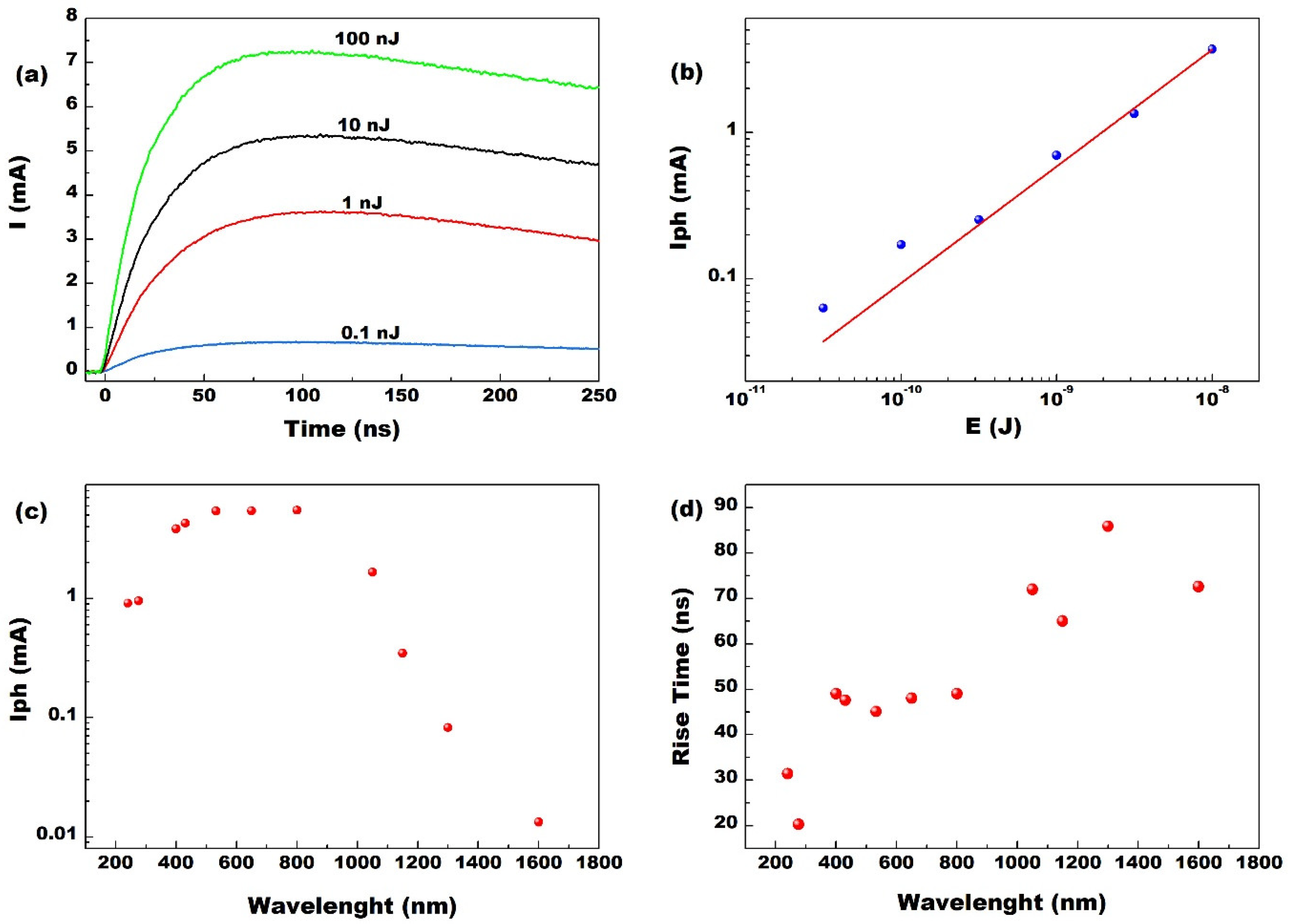
To investigate the response rate and explore the feasibility of the realized devices for practical applications as ultra-fast PDs, the NSH area was illuminated by a 35-fs pulsed laser used as light source. In Figure 3a, the time dependence of the photocurrent value, I, is reported after the junction is illuminated by a single laser pulse tuned at λ = 800 nm at different energies showing the high sensitivity of our photodetectors. Iph, measured by taking the difference between maximum and minimum in PD response peaks for λ = 800 nm in energy scale is shown in Figure 3b. The data are well approximated by a power law y = xα with α = 0.82 ± 0.4 confirming the possibility to use the device as a linear detector. Similar results are obtained for several incident λ from the UV (240 nm) up to the IR (1600 nm). For a given laser intensity, the measured photocurrent depends on the incident light wavelength. This dependence is shown in Figure 3c where Iph is reported as a function of λ for E = 100 nJ. Iph increases up to 800 nm and then decreases following the absorption spectrum of Si (as reported in EQE spectra Figure 2a) but presenting a tail in the NIR region. From these measurements, the ability of the NSH PD in absorbing and responding to a wide spectral range, operating in a large incident optical power range without any need to be powered, was proved. The Si p-n junction PDs do not operate in the IR spectral region because the optical absorption is limited by the Si band gap energy around 1060 nm. On the other hand, SWCNT films were proven to absorb and photogenerate electrical charges ascribed to the presence of van Hove singularities in their electronic density of states of CNT [10,31,33,34]. These optical transitions in SWCNTs are present both for wavelengths in the visible and in the IR range [35]. Therefore, our experimental results highlight that the SWCNT film not only acts as a transparent window, heterojunction constituent, and collector of photogenerated charges in Si, but the SWCNTs actively behave as photocurrent generators. However, given the high transparency of the film, we can note this contribution only in the IR range (in our case for λ= 1300 and 1600 nm), where there is no signal from the optical absorption of Si, predominating the electrical response of the device up to about 1060 nm. Further, normally, a typical Si p-n junction PD also does not operate in UV spectral region despite the Si absorption coefficient in this region being very high. This is because UV radiation is mostly absorbed very close to the surface where charge recombination is very important, thus preventing photo charges from reaching the junction, usually several μm from the surface. In our NSH PD devices, the photogenerated charges can instead safely reach the junction which is very close to the Si surface thanks to the small thickness of CNT film. The rise time, τr, measured as the time difference between the 90% and 10% of the current peak value, is shown in Figure 3d as a function of λ at E = 100 nJ. From this figure emerges the ability of our NSH PD to detect a fast multicolor signal, responding fast (some tens of nanoseconds) to a fs laser pulse, with results comparable to those reported for commercial PDs [22]. Interestingly, τr increases for higher wavelengths due to lower absorption coefficient and different penetration depth and diffusion length inside the device. A detailed analysis and explanation of this mechanism is reported elsewhere [36] for a similar PD device based on graphene/silicon heterojunction.
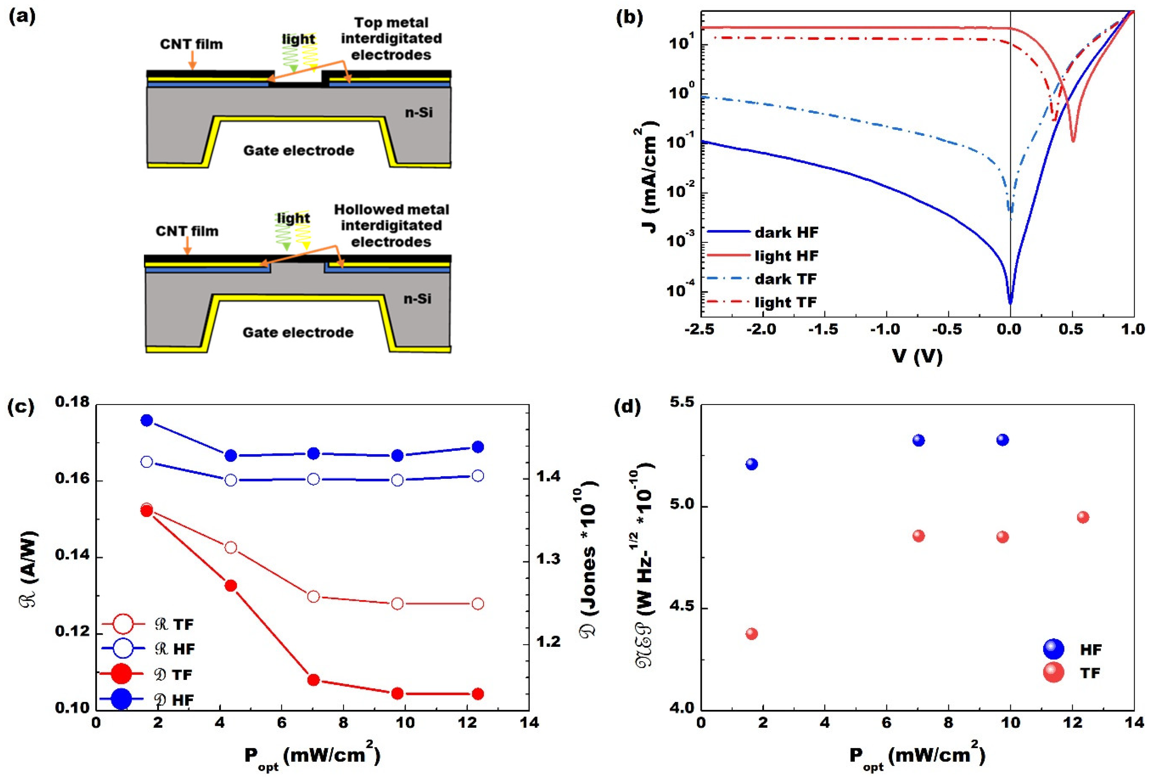
The reported device performances in terms of noise dark current, responsivity, and rise time can be further improved by acting on the quality of the nanotubes/Si interface. For this purpose, a new type of structure for the upper interdigitated contact was conceived and designed. The new generation of substrates is realized with the fingers of the top contact hollowed inside the n-Si region to form a smooth surface without protuberances due to the electrodes (Figure 4a, bottom panel). In the following, this configuration is referred to as the hollowed finger (HF) one, while the usual device design is referred to as the top finger (TF) one (Figure 4a, top panel). In Figure 4b, the I–V features acquired in dark conditions and under 100 mW/cm2 white light illumination for two different devices are reported. The straight lines correspond to the hollowed fingers device, while the dashed lines correspond to the device with the top electrodes evaporated on top of the Si region. Both devices are realized with the same SWCNT film, with the same optical (T ≈ 50%) and electrical properties (Rs), and have 10 interdigitated fingers (five per side). This means that the differences in I–V curves are only due to the difference in the geometry (hollowed or not) of the fingers. From the dark characteristic, the decrease of about one order of magnitude in the saturation current I0 can be noticed, decreasing from 25.6 nA to 3.4 nA in the new generation device. Moreover, using the previous reported equation for modelling the NSH junction, the series resistance RS and the ideality factor n, which reduces by almost 50%, passing from 8.78 Ω to 4.96 Ω and from 8.2 Ω to 4.4 Ω, respectively, were extrapolated. Besides, when illuminated, the device performances using the new design concept improve; in fact, the short circuit current density (JSC) increases by more than 100%, going from 10.4 to 21.0 mA/cm2, and also the open circuit voltage (VOC) grows from 0.35 to 0.51 V. In addition, there is also an increase of the responsivity, the detectivity, and the 𝒩𝒫, obtained by illuminating with EQE on–off cycles of several power 475 nm LED. All these improvements can be ascribed to the fact that in the devices with the electrode hollowed in Si, when the nanotube film is deposited on the top surface touching both the n-Si region and the electrode metal region, it finds a flat surface and is able to settle more effectively without leaving empty or uneven spaces. In fact, being a few tens of nanometers thick, while the evaporated electrode is 150 nm thick, the SWCNT film in the previous substrates must follow the metal profile on the Si surface, probably creating areas where the intimate contact between the SWCNT film and the Si active area is not reached.
Finally, it is important to highlight that in PV mode, the measurements are all carried out in the absence of polarization V = 0, i.e., no energy must be spent to power the device that works without any associated electronics, (signal amplifiers, power supplies, control cards, filters, etc.). Indeed, the electrical signal is directly transmitted by the PD electrodes to coaxial cables that can be connected to any current or voltage reading system. In this way the signal does not lose its characteristics such as speed or power, undergoing as few manipulations as possible. Another advantage of this approach is the fact that this small device is very light, and since it does not need other associated devices to operate, it can be used in situations where small dimensions and low weight are essential, such as in space applications.

3.2. Photoconductive Configuration

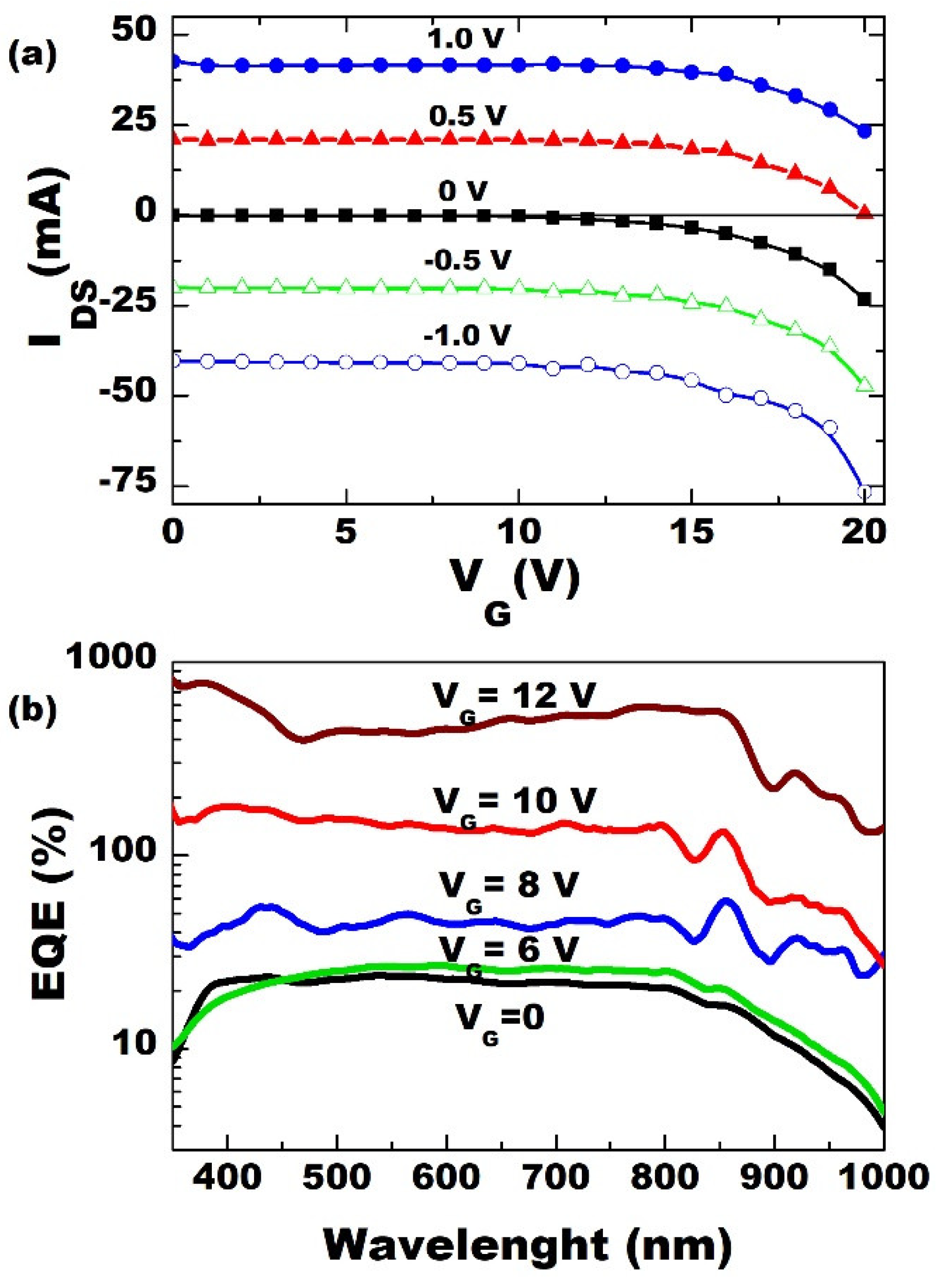
In PC configuration, the PD acts as a 3-terminal device: the output current signal is recorded between the interdigitated S and D electrodes, connected by the SWCNT film, while the G electrode on the bottom side of the Si substrate is used as an external input control providing an electric potential VG at the ends of the heterojunction. VG is applied relative to the source electrode, S. In Figure 5a, the ISD-versus-VG feature at different values VSD of the voltage applied to the SWCNT film in dark conditions is shown. The curves are representative of a typical trend of a 3-terminal device: at low VG, the current flowing inside the CNT is constant, but from VG ≈ 15V it starts to increase, due to an avalanche effect, and rapidly intensifies as VG = 20 V. The beginning of the avalanche region starts off at a noticeable low voltage value compared to commercial PDs which need even a 100 V bias to reach the same operating point [37]. In this configuration, when VG = 0 and the device is in the dark, the current measured between the interdigitated electrodes is linear with respect to VSD, and the ISD-versus-VSD characteristics represent the resistance of the CNT film. If the device is illuminated, a higher current value at the same VDS has been measured: now, there are more free charges available in the film, as the minority positive charges (holes), photogenerated mainly in the Si region, crossed the potential barrier of the junction and flowed into the CNTs thanks to the junction potential Vbi generated at the nanotubes/n-Si interface. If a VG > 0 is applied, the junction is reverse polarized, and a higher injection of holes occurs inside the CNT film, driven in this case not only by Vbi, but also by VG, while for VG < 0 and VG > Vbi, the NSH is directly polarized, and the majority charges (electrons) flow inside the SWCNT film. A detailed explanation of the voltage doping mechanism in our detectors has been recently reported in [21]. Here, we report only the improvements in the performance of our devices when a positive voltage was applied to the gate electrode because usually in photodiode devices, the operation involves a reverse bias of the junction which is more easily controllable and tunable by the gate voltage. A hole mobility μh = 5 × 105 cm2/V·s was obtained from the PC I–V measurements [21] resulting in some orders of magnitude higher than other CNT-based fast switching devices [38]. To support the 3-terminal photoconductive proposed mechanism of photodetection, measurements of the EQE collected between S-D terminals were performed in the wavelength range 300 nm–1000 nm. The results reported in Figure 5b point out that for VG = 0 the EQE shape is similar to that of a Si p-n junction and very close to the EQE acquired in PV mode (Figure 2a) [39]. This occurs because the current flowing in the CNT film comes mainly from the minority photocarriers generated in the n-Si substrate injected by Vbi. It is worth noting that EQE values measured for VG = 0 in PV configuration are higher than the ones obtained in the PC mode. This is due to the fact that in the PV mode, the e and h photocharges are both separated by Vbi at the SWCNT/Si interface, while in PC mode, the collected photocharges are just holes driven through the junction by the same built-in potential. However, as shown in Figure 5b, for VG > 0 the EQE hugely increases, exceeding 100%, since the number of holes collected by the CNT in the PC mode are enhanced by the action of VG driving the junction in the avalanche regime, thus giving rise to a voltage doping of the PD.
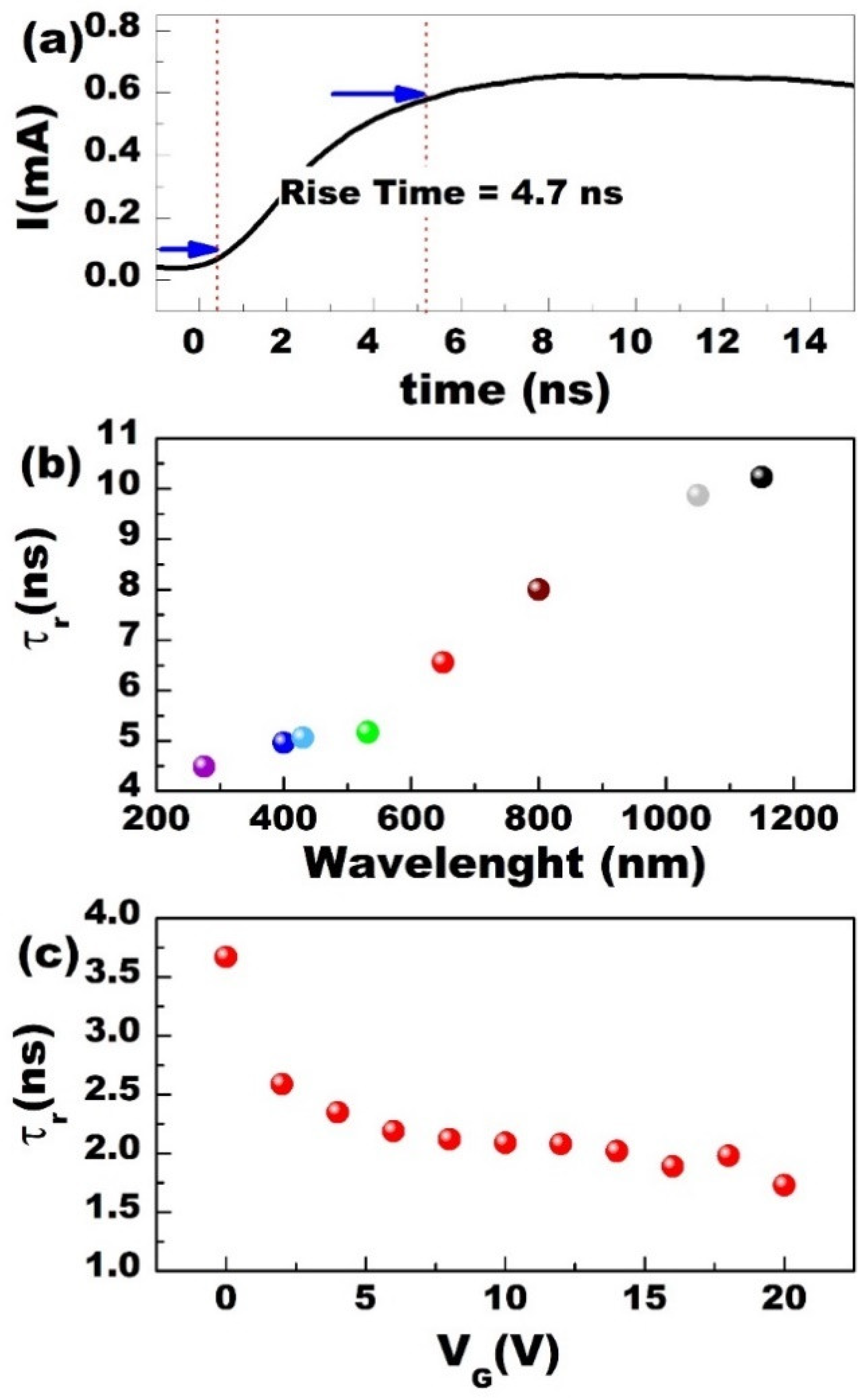
The NSH PD ability to detect ultra-fast signals in PC mode was tested lighting the device with the fs laser source. Figure 6a reports the photocurrent response for a single laser pulse (λ = 275 nm) with incident photon energy of 100 nJ in absence of voltage doping (VG = 0). The measured rise time is τr = (4.7 ± 0.1) ns. In Figure 6b the rise time vs. λ at VG = 0 and E = 100 nJ is shown. As in the case of the PV mode, τr increases with increasing wavelength ranging from 4.7 ns in the UV region to about 10 ns in the IR region, suggesting a similar mechanism in the two different configurations [40]. Nevertheless, the PDs operating in the PC mode appear faster in their response to the light pulse with respect to the PV configuration. In the PC mode, in fact, the signal measured by the external circuit is composed only of the holes mostly photogenerated in the Si substrate close to the SWCNT/Si junction and injected into the CNT film. This hole current takes less time to reach the top metal contacts than the current of electrons and holes generated in the PV mode. In this last case, indeed, electrons have to move through all the Si substrate’s thickness to be collected at the G electrode [22]. The PD response can be further improved by applying a VG > 0 which means directly polarizing the junction. This is shown in Figure 6c, where τr is reported as a function of VG for λ = 275 nm: for VG = 20 V, τr reaches the minimum measured value of about 1.5 ns. Similar results are obtained for all the other wavelengths investigated from UV (λ = 240 nm) to IR (λ = 1600 nm). This means, therefore, that voltage doping, induced by VG, not only increases the photocurrent thanks to an avalanche mechanism, but also increases the drift velocity of the photogenerated charges which take less time to reach the electrodes and be collected.

4. Conclusions

The main characteristics of the carbon nanotubes/silicon heterojunction-based photodetectors were shown, highlighting the great potential of these devices in many different applications thanks to their adaptability to different types of measurements. The carbon nanotube film was obtained by devising a very simple, inexpensive, scalable, fast, and low-environmental-impact method that allows to modulate and tune the optical and electrical properties of the device by only controlling the amount of SWCNT dispersion used. The top–down configuration was realized with all the electrical contacts already set up before the film was deposited, so that once the substrates were created in the foundry, it was no longer necessary to work in situations of particular attention to pressure, temperatures, or cleaning to fabricate the detector. It was shown that the NSH detectors, working in the two different modes, the photovoltaic and the photoconductive one, are able to detect a light signal in a large and wide incident spectrum ranging from 240 to 1600 nm, responding fast with rise times of a few nanoseconds with excellent sensitivity and detectivity comparable to commercial devices currently available. It was also shown that the carbon nanotube film can be used in field effect devices thanks to the possibility of varying its electronic properties through the injection of charges by means of a back-gate voltage doping. This is possible thanks to the conceived structure of the device which takes the advantage of the incredible optical and electrical properties of single walled carbon nanotubes.

Author Contributions

Conceptualization, M.S. (Matteo Salvato), M.D.C. and P.C.; validation, M.S. (Mattia Scagliotti), M.S. (Matteo Salvato) and P.C.; formal analysis, M.S. (Mattia Scagliotti); investigation, M.S. (Mattia Scagliotti), F.F., D.C., L.D.M. and M.S. (Matteo Salvato); resources, M.D.C., D.C., M.B. and P.C.; writing—original draft preparation, M.S. (Mattia Scagliotti) and P.C.; writing—review and editing, all the authors; visualization, M.S. (Mattia Scagliotti) and P.C.; supervision, M.S. (Matteo Salvato) and P.C. All authors have read and agreed to the published version of the manuscript.

Funding

This research received no external funding.

Institutional Review Board Statement

Not applicable.

Informed Consent Statement

Not applicable.

Data Availability Statement

Data is contained within the article.

Acknowledgments

In this section you can acknowledge any support given which is not covered by the author contribution or funding sections. This may include administrative and technical support, or donations in kind (e.g., materials used for experiments).

Conflicts of Interest

The authors declare no conflict of interest.

References

  1. Saito, R.; Dresselhaus, G.; Dresselhaus, M.S. Physical Properties of Carbon Nanotubes; Imperial College Press: London, UK, 1998; p. xii. 259p. [Google Scholar]
  2. Tans, S.J.; Devoret, M.H.; Dai, H.J.; Thess, A.; Smalley, R.E.; Geerligs, L.J.; Dekker, C. Individual single-wall carbon nanotubes as quantum wires. Nature 1997, 386, 474–477. [Google Scholar] [CrossRef] [Green Version]
  3. Dekker, C. Carbon nanotubes as molecular quantum wires. Phys. Today 1999, 52, 22–28. [Google Scholar] [CrossRef]
  4. Javey, A.; Guo, J.; Wang, Q.; Lundstrom, M.; Dai, H.J. Ballistic carbon nanotube field-effect transistors. Nature 2003, 424, 654–657. [Google Scholar] [CrossRef] [PubMed]
  5. Jorio, A.; Dresselhaus, G.; Dresselhaus, M.S. Carbon Nanotubes: Advanced Topics in the Synthesis, Structure, Properties, and Applications; Springer: Berlin, Germany; New York, NY, USA, 2008; p. xxiv. 720p. [Google Scholar]
  6. Kaiser, A.B. Electronic transport properties of conducting polymers and carbon nanotubes. Rep. Prog. Phys. 2001, 64, 1–49. [Google Scholar] [CrossRef]
  7. De Nicola, F.; Salvato, M.; Cirillo, C.; Crivellari, M.; Boscardin, M.; Passacantando, M.; Nardone, M.; De Matteis, F.; Motta, N.; De Crescenzi, M.; et al. 100% internal quantum efficiency in polychiral single-walled carbon nanotube bulk heterojunction/silicon solar cells. Carbon 2017, 114, 402–410. [Google Scholar] [CrossRef]
  8. De Nicola, F.; Salvato, M.; Cirillo, C.; Crivellari, M.; Boscardin, M.; Scarselli, M.; Nanni, F.; Cacciotti, I.; De Crescenzi, M.; Castrucci, P. Record efficiency of air-stable multi-walled carbon nanotube/silicon solar cells. Carbon 2016, 101, 226–234. [Google Scholar] [CrossRef] [Green Version]
  9. Jia, Y.; Li, P.X.; Wei, J.Q.; Cao, A.Y.; Wang, K.L.; Li, C.L.; Zhuang, D.M.; Zhu, H.W.; Wu, D.H. Carbon nanotube films by filtration for nanotube-silicon heterojunction solar cells. Mater. Res. Bull. 2010, 45, 1401–1405. [Google Scholar] [CrossRef]
  10. Castrucci, P. Carbon nanotube/silicon hybrid heterojunctions for photovoltaic devices. Adv. Nano Res. 2014, 2, 23–56. [Google Scholar] [CrossRef] [Green Version]
  11. Tune, D.D.; Flavel, B.S. Advances in Carbon Nanotube-Silicon Heterojunction Solar Cells. Adv. Energy Mater. 2018, 8, 1703241. [Google Scholar] [CrossRef]
  12. Tune, D.D.; Mallik, N.; Fornasier, H.; Flavel, B.S. Breakthrough Carbon Nanotube-Silicon Heterojunction Solar Cells. Adv. Energy Mater. 2020, 10, 1903261. [Google Scholar] [CrossRef] [Green Version]
  13. Tune, D.D.; Shirae, H.; Lami, V.; Headrick, R.J.; Pasquali, M.; Vaynzof, Y.; Noda, S.; Hobbie, E.K.; Flavel, B.S. Stability of Chemically Doped Nanotube-Silicon Heterojunction Solar Cells: Role of Oxides at the Carbon-Silicon Interface. ACS Appl. Energy Mater. 2019, 2, 5925–5932. [Google Scholar] [CrossRef]
  14. Rigoni, F.; Pintossi, C.; Drera, G.; Pagliara, S.; Lanti, G.; Castrucci, P.; De Crescenzi, M.; Sangaletti, L. A cross-functional nanostructured platform based on carbon nanotube-Si hybrid junctions: Where photon harvesting meets gas sensing. Sci. Rep. 2017, 7, 44413. [Google Scholar] [CrossRef] [PubMed] [Green Version]
  15. Zeng, Q.S.; Wang, S.; Yang, L.J.; Wang, Z.X.; Pei, T.; Zhang, Z.Y.; Peng, L.M.; Zhou, W.W.; Liu, J.; Zhou, W.Y.; et al. Carbon nanotube arrays based high-performance infrared photodetector [Invited]. Opt. Mater. Express 2012, 2, 839–848. [Google Scholar] [CrossRef]
  16. Ambrosio, A.; Aramo, C.; Battiston, R.; Castrucci, P.; Cilmo, M.; De Crescenzi, M.; Fiandrini, E.; Grossi, V.; Guarino, F.; Maddalena, P.; et al. Innovative carbon nanotube-silicon large area photodetector. J. Instrum. 2012, 7, 08013. [Google Scholar] [CrossRef]
  17. Xie, Y.; Gong, M.G.; Shastry, T.A.; Lohrman, J.; Hersam, M.C.; Ren, S.Q. Broad-Spectral-Response Nanocarbon Bulk-Heterojunction Excitonic Photodetectors. Adv. Mater. 2013, 25, 3433–3437. [Google Scholar] [CrossRef] [PubMed]
  18. Zhang, T.F.; Li, Z.P.; Wang, J.Z.; Kong, W.Y.; Wu, G.A.; Zheng, Y.Z.; Zhao, Y.W.; Yao, E.X.; Zhuang, N.X.; Luo, L.B. Broadband photodetector based on carbon nanotube thin film/single layer graphene Schottky junction. Sci. Rep. 2016, 6, 38569. [Google Scholar] [CrossRef] [Green Version]
  19. Salvato, M.; Scagliotti, M.; De Crescenzi, M.; Crivellari, M.; Prosposito, P.; Cacciotti, I.; Castrucci, P. Single walled carbon nanotube/Si heterojunctions for high responsivity photodetectors. Nanotechnology 2017, 28, 435201. [Google Scholar] [CrossRef] [PubMed]
  20. Scagliotti, M.; Salvato, M.; De Crescenzi, M.; Boscardin, M.; Castrucci, P. Influence of the contact geometry on single-walled carbon nanotube/Si photodetector response. Appl. Nanosci. 2018, 8, 1053–1058. [Google Scholar] [CrossRef]
  21. Salvato, M.; Scagliotti, M.; De Crescenzi, M.; Crivellari, M.; Messi, R.; Castrucci, P. Increasing Efficiency in Single-Walled Carbon Nanotube/n-Si Photodetectors by Voltage Doping. IEEE Trans. Nanotechnol. 2018, 17, 837–840. [Google Scholar] [CrossRef]
  22. Salvato, M.; Scagliotti, M.; De Crescenzi, M.; Boscardin, M.; Attanasio, C.; Avallone, G.; Cirillo, C.; Prosposito, P.; De Matteis, F.; Messi, R.; et al. Time response in carbon nanotube/Si based photodetectors. Sens. Actuators A Phys. 2019, 292, 71–76. [Google Scholar] [CrossRef]
  23. Aramo, C.; Ambrosio, M.; Bonavolonta, C.; Boscardin, M.; Crivellari, M.; de Lisio, C.; Grossi, V.; Maddalena, P.; Passacantando, M.; Valentino, M. Large area CNT-Si heterojunction for photodetection. Nucl. Instrum. Meth. A 2017, 845, 12–15. [Google Scholar] [CrossRef]
  24. Bonavolonta, C.; Aramo, C.; Ambrosio, M.; Boscardin, M.; Consiglio, L.; Crivellari, M.; Fiandrini, E.; Passacantando, M.; Santucci, S.; Valentino, M. UV photo-responsivity of a large-area MWCNT-Si photodetector operated at cryogenic temperature. Eur. Phys. J. Plus 2018, 133, 1–6. [Google Scholar] [CrossRef]
  25. Kato, H.; Nakamura, A.; Horie, M. Behavior of surfactants in aqueous dispersions of single-walled carbon nanotubes. RSC Adv. 2014, 4, 2129–2136. [Google Scholar] [CrossRef]
  26. Kumar, C.S.S.R. UV-VIS and Photoluminescence Spectroscopy for Nanomaterials Characterization; Springer: Berlin/Heidelberg, Germany, 2013. [Google Scholar]
  27. De Nicola, F.; Pintossi, C.; Nanni, F.; Cacciotti, I.; Scarselli, M.; Drera, G.; Pagliara, S.; Sangaletti, L.; De Crescenzi, M.; Castrucci, P. Controlling the thickness of carbon nanotube random network films by the estimation of the absorption coefficient. Carbon 2015, 95, 28–33. [Google Scholar] [CrossRef]
  28. Bagolini, A.; Boscardin, M.; Conci, P.; Crivellari, M.; Giacomini, G.; Mattedi, F.; Piemonte, C.; Ronchin, S.; Zorzi, N.; Benkechkache, M.A.; et al. Micromachined silicon radiation sensors—Part 2: Fabrication technologies. In Proceedings of the 2015 XVIII AISEM Annual Conference, Trento, Italy, 3–5 February 2015; pp. 1–4. [Google Scholar]
  29. Catone, D.; Di Mario, L.; Martelli, F.; O’Keeffe, P.; Paladini, A.; Cresi, J.S.P.; Sivan, A.K.; Tian, L.; Toschi, F.; Turchini, S. Ultrafast optical spectroscopy of semiconducting and plasmonic nanostructures and their hybrids. Nanotechnology 2020, 32, 025703. [Google Scholar] [CrossRef] [PubMed]
  30. Rossi, G.; Pasquini, L.; Catone, D.; Piccioni, A.; Patelli, N.; Paladini, A.; Molinari, A.; Caramori, S.; O’Keeffe, P.; Boscherini, F. Charge carrier dynamics and visible light photocatalysis in vanadium-doped TiO2 nanoparticles. Appl. Catal. B Environ. 2018, 237, 603–612. [Google Scholar] [CrossRef] [Green Version]
  31. Del Gobbo, S.; Castrucci, P.; Fedele, S.; Riele, L.; Convertino, A.; Morbidoni, M.; De Nicola, F.; Scarselli, M.; Camilli, L.; De Crescenzi, M. Silicon spectral response extension through single wall carbon nanotubes in hybrid solar cells. J. Mater. Chem. C 2013, 1, 6752–6758. [Google Scholar] [CrossRef]
  32. Sze, S.M. Semiconductor Devices: Physics and Technology; John Wiley & Sons: Hoboken, NJ, USA, 2008. [Google Scholar]
  33. Bindl, D.J.; Shea, M.J.; Arnold, M.S. Enhancing extraction of photogenerated excitons from semiconducting carbon nanotube films as photocurrent. Chem. Phys. 2013, 413, 29–34. [Google Scholar] [CrossRef]
  34. Barazzouk, S.; Hotchandani, S.; Vinodgopal, K.; Kamat, P.V. Single-Wall Carbon Nanotube Films for Photocurrent Generation. A Prompt Response to Visible-Light Irradiation. J. Phys. Chem. B 2004, 108, 17015–17018. [Google Scholar] [CrossRef]
  35. Kataura, H.; Kumazawa, Y.; Maniwa, Y.; Umezu, I.; Suzuki, S.; Ohtsuka, Y.; Achiba, Y. Optical properties of single-wall carbon nanotubes. Synth. Met. 1999, 103, 2555–2558. [Google Scholar] [CrossRef]
  36. Scagliotti, M.; Salvato, M.; De Crescenzi, M.; Kovalchuk, N.G.; Komissarov, I.V.; Prischepa, S.L.; Catone, D.; Di Mario, L.; Boscardin, M.; Crivellari, M.; et al. Femtosecond light pulse response of photodetectors based on Graphene/n-Si heterojunctions. Carbon 2019, 152, 643–651. [Google Scholar] [CrossRef]
  37. Hamamatsu Handbook. Available online: https://www.hamamatsu.com/sp/ssd/doc_en.html (accessed on 10 October 2020).
  38. Martel, R.; Schmidt, T.; Shea, H.R.; Hertel, T.; Avouris, P. Single- and multi-wall carbon nanotube field-effect transistors. Appl. Phys. Lett. 1998, 73, 2447–2449. [Google Scholar] [CrossRef] [Green Version]
  39. Nelson, J.A. The Physics of Solar Cells; Imperial College Press: London, UK, 2003. [Google Scholar]
  40. Scagliotti, M.; Salvato, M.; De Crescenzi, M.; Castrucci, P.; Kovalchuk, N.G.; Komissarov, I.V.; Prischepa, S.L.; Catone, D.; Di Mario, L.; Boscardin, M.; et al. 2D Carbon Material/Silicon Heterojunctions for Fast Response Self-Powered Photodetector. Int. J. Nanosci. 2019, 18, 1940088. [Google Scholar] [CrossRef]
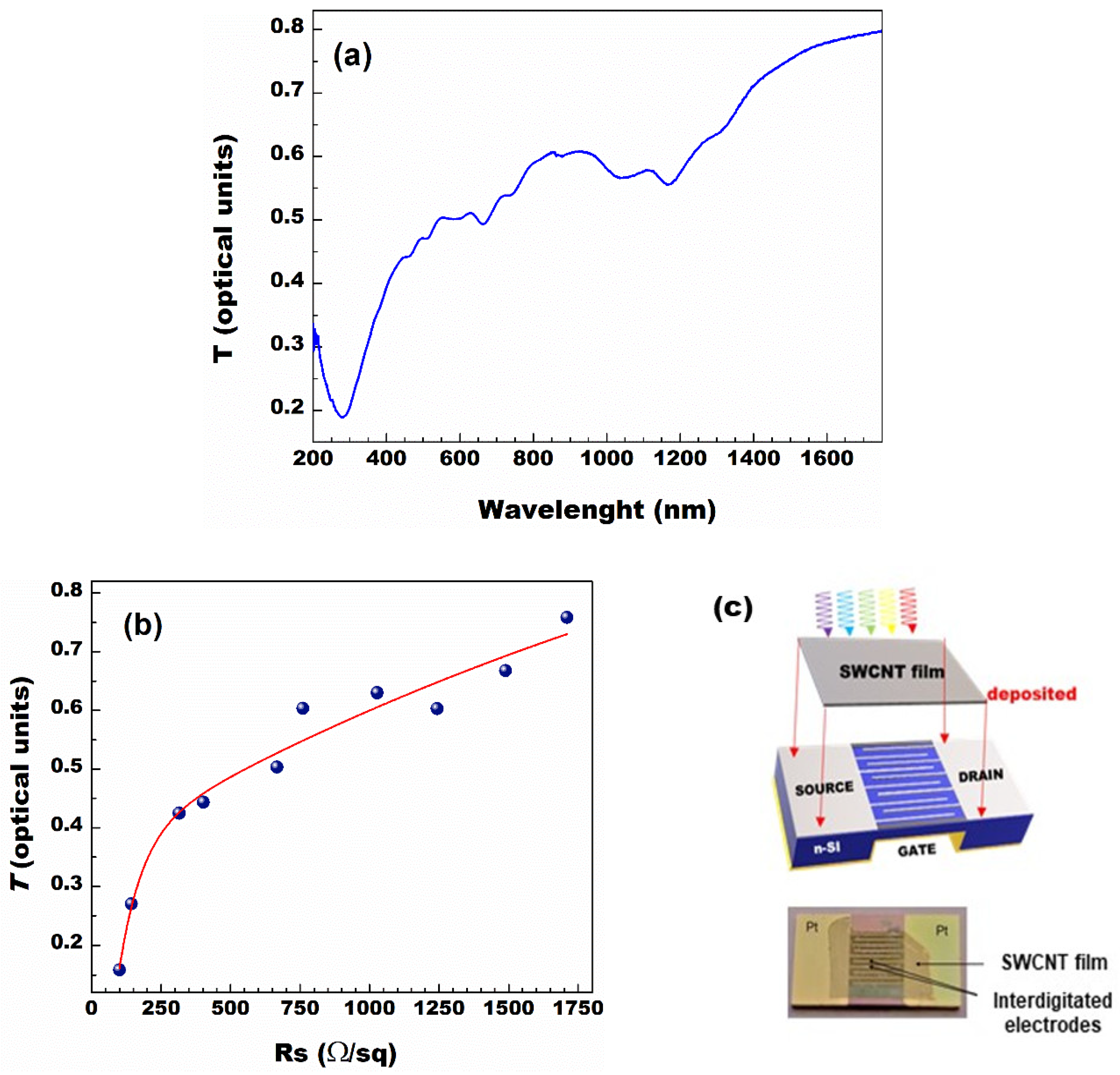
Figure 1. (a) Optical transmittance (T) of single wall carbon nanotube (SWCNT) films as a function of the incident photon wavelength, λ. (b) Optical transmittance (T) of SWCNT films at fixed incident wavelength λ = 550 nm vs their sheet resistance (RS). The red curve is a fit obtained following the Equation (1). The free parameter in the fit is the ratio σac/σdc which is found to be equal to 1.2 ± 0.1. (c) Top panel: Sketch of the device. In order to better display the multifinger top electrode, the SWCNT film is artificially reported lifted with respect to the active area. Red arrows indicate where the SWCNT film was deposited through the dry-transfer printing process. Bottom panel: a picture of the device. Note the high transparency of the SWCNT film that allows to still see the interdigitated contacts.
Applsci 11 00606 g001
Figure 2. (a) Current versus voltage characteristics acquired in dark conditions (dark) and under illumination (light). Inset: typical external quantum efficiency of n-silicon heterojunction (NSH) photodetector (PD) sample; (b) PD response under dark and light conditions (frequency 10 Hz) when the junction is lightened with different LED light power (green curve: 1.4 mW/cm2; turquoise curve: 1.8 mW/cm2; violet curve: 2.2 mW/cm2; yellow curve: 2.5 mW/cm2; red curve: 2.8 mW/cm2); (c) responsivity (closed symbols, left axis) and detectivity (open symbols, right axis) of the three different samples with different optical transmittance at λ = 550 nm T = 63% for red symbols, T = 44% for green symbols, and T = 42% for blue symbols; (d) responsivity as a function of Popt for PDs with different numbers of fingers N. Here the SWCNT film optical transmittance at λ = 550 nm is T = 49%. Data reported in (ac) have been adapted from [19] and those in (d) from [20].
Applsci 11 00606 g002
Figure 3. (a) Photocurrent response of the PD to a 35-fs pulsed laser at different beam energy, tuned to photon wavelength, λ = 800 nm. (b) Photocurrent difference, Iph, between maximum and minimum in PD response peaks vs the laser light pulse energy for λ = 800 nm; in red, the curve obtained by fitting the experimental data with a power function is shown, highlighting a linear behavior; (c) Iph as a function of photon wavelength measured with an incident fs laser light pulse energy, E = 100 nJ and (d) rise time acquired as a function of photon wavelength of an incident 35 fs laser pulse at energy E = 100 nJ.
Applsci 11 00606 g003
Figure 4. (a) Sketch of the devices used: in the top panel the one with the Si active area at a lower level with respect to the metal multifinger electrodes (henceforth, named TF); in the lower panel, the one with the Si active area at the same level of the multifinger metal contacts (hereafter, called HF); (b) Current-voltage curves acquired in dark (solid lines) and under 100 mW/cm2 white light illumination (dot-dashed curves) conditions for the TF (red) and HF (blue) devices; (c) responsivity (open circles) and detectivity (solid circles) as a function of the 475 nm LED light power for the TF (red) and HF (blue) PDs; (d) noise equivalent power as a function of the 475 nm LED light power for the TF (red) and HF (blue) PDs.
Applsci 11 00606 g004
Figure 5. (a) Source-drain current IDS vs gate voltage VG acquired in dark conditions for different values of VDS; (b) External quantum efficiency measured between S and D terminals as a function of the wavelength for different values of the gate voltage VG.
Applsci 11 00606 g005
Figure 6. (a) Response to a single 35-fs laser pulse of NSH PD for incident light energy of 100 nJ and wavelength of 275 nm. The arrows indicate the 10% and the 90% of the pulse height used as a criterion for the rise time estimation; (b) rise time, τr, versus wavelength under 35 Lfs pulsed laser source for incident light energy of 100 nJ; (c) rise time, τr, measured at λ = 275 nm as a function of the gate voltage, VG.
Applsci 11 00606 g006
Publisher’s Note: MDPI stays neutral with regard to jurisdictional claims in published maps and institutional affiliations.