1. Introduction
The aim of this paper is to investigate the dynamic properties of the sloshing phenomenon inside rectangular tanks characterised by different bottom shapes. The interest is to investigate two particular aspects of the fluid–structure interaction, namely the natural sloshing frequency of the fluid inside the tank and its damping feature. The latter is related, among the other features, to the beating phenomenon [
1], characterised by the undesired dynamic forces induced on the substructure due to sloshing motion.
The understanding of the aforementioned aspects is important in the framework of the vibration control [
2,
3,
4], especially in the design process of containers or passive damping devices exploiting fluid motion, since the motions of the container and the liquid are coupled and the resonance phenomena could occur [
5,
6,
7,
8,
9,
10,
11,
12,
13]. The dynamics of the coupled system generally depend on the container geometry and the amount of the inner liquid. At a first glance, such a problem may be analysed as the case of a bifilar pendulum, even if the physics of such a pendulum is quite different from the sloshing motion inside a container which moves along the horizontal direction. In the case of a container suspended as a bifilar pendulum, gravity directly provides the restoring force, working in concert with, or in opposition, to the hydrodynamic forces, so that both in-phase and antiphase oscillations can occur [
14,
15,
16]. In the horizontal sloshing case, gravity does not directly affect the motion of the container, being indirectly involved through the liquid motion, whereby the hydrodynamic pressure of the liquid on its walls provides the restoring force. Hence, the sloshing liquid is expected to be out of phase with the oscillating tank, always accumulating in the direction opposite to that of the containers’ motion.
In some cases, the interaction between the liquid motion and the substructure could produce significant advantages in the overall dynamics of the coupled system. A classical example is represented by the so called Tuned Sloshing Dampers (TSD) [
17,
18,
19,
20,
21]. Their working mechanism is based on the dynamic response of the liquid motion inside the tank and its interaction with the dynamic input, generally transmitted by the structure on which it is installed [
22]. The sloshing forces transferred to the structure are called
base shear forces. In real life applications, structural systems are typically induced to move due to external actions, e.g., wind loads or earthquakes and the liquid motion tends to come with a phase shift with respect to the structural motion, depending on the physical properties of the liquid itself, the tank geometries and the structural dynamics properties. This phenomenon results in a dissipation energy by virtue of the energy exchange between the structural system in motion and the device itself. During the dynamic motion, an energy amount is temporarily stored and can be effective in vibration damping when released back to the structure. This energy exchange becomes more effective if a tuning process is properly carried out, so that the sloshing forces are able to reduce the structural vibration and mitigate resonance effects [
23].
When excited, the water wave motion quickly develops, but on the contrary, the established wave motion does not vanish immediately after the excitation is over. This results in the so-called beating phenomenon, consisting of long lasting undesired oscillating pulses transmitted to the substructure with an amplitude modulation instead of an exponentially decaying trend. This behaviour of continuous wave motion is often regarded as an adverse effect, for instance within the structural control framework. The beating phenomenon is due to a fraction of the energy absorbed by the device being transferred back to the structure rather than being dissipated within the device itself, which is a result of the complex
liquid-tank system [
24]. The amplitude modulation is a consequence of the near resonating condition between structural vibration and water sloshing. Damping in liquid-tank systems is generated by wave breaking and the impact of liquid on the container walls, as a result of a complex free surface fluid–structure interaction problem [
25,
26,
27]. For the interested reader, damping and beating phenomena have been widely treated in the literature on mechanical vibrations (e.g., see [
28]).
Given the relevance of fluid–structural interaction phenomena in different branches of science and engineering, in recent years several studies have been developed in order to deeply understand the dynamics of sloshing phenomena and model their behaviour in mechanical coupled systems [
29,
30,
31] with the majority of the applications in the field of civil engineering applications [
32]. In this framework, the use of tanks with different bottom shapes has, in fact, revealed interesting properties for technological applications, such as the Tuned Sloshing Dampers (TSDs) not only for the case of sloped bottom shape which represents one of the most studied [
33,
34,
35,
36,
37,
38] but also for different various geometries [
39,
40,
41,
42,
43].
Besides the civil engineering applications, significant advantages can be obtained also in different fields by simply modifying the bottom shape of the container. In this way, it is possible to operate on the main properties of the sloshing phenomenon, i.e., natural frequencies, damping ratios, effective mass and stiffness, which regulate the effectiveness of the coupled dynamic systems. Even if it is known that the fluid dynamic response is affected by the bottom geometry of the tank, there are some aspects which are still open and require more investigations. In this work an experimental campaign aimed at investigating the natural sloshing frequencies and the damping properties of a liquid inside a tank characterised by different bottom shapes is carried out and some results compared through analytical solutions available in the literature.
2. Theoretical Aspects
The theoretical background of the sloshing motion dynamics has been largely explored in the literature. For the scope of this work, the theoretical aspects related to the analysis of the natural sloshing frequencies for three bottom geometries have been considered, namely the flat, the sloped and the circular shape.
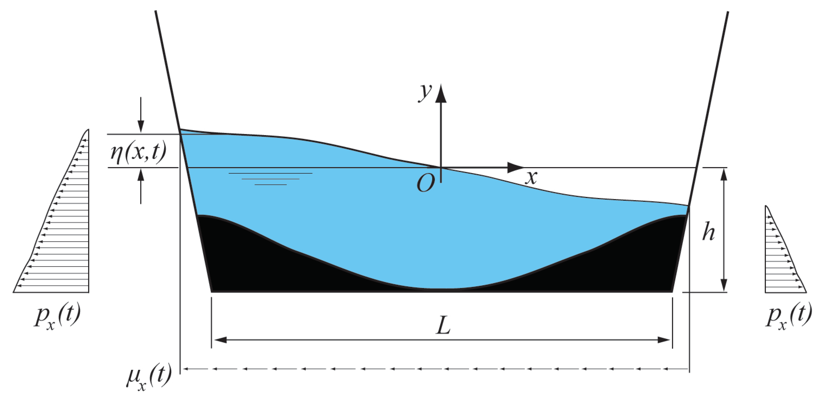
The physics of the sloshing problem is represented for the general case in
Figure 1, with
being the considered coordinate system. The total mass of the liquid is denoted by
. A motion of the internal liquid generates a variation the free surface, whose kinematics is described by
denoting the vertical movement over the horizontal line. Consequently, fluid horizontal pressures
and shear actions
over the sides of the tank produce an overall horizontal force,
, which represents the base shear force developing between the tank and the substructure, obtained by their integral over the dynamic wet perimeter
For the flat bottom case, a tank with base length
L partially filled with a liquid having depth
h has been considered. The value of the ratio
approaching zero determines the well-known range of validity of the small amplitude wave theory [
44]. Within this range, linear long wave theory can be applied. The classical reference studies, based on the linear wave theory, date back to the end of the nineteenth century, and in particular to the seminal work of Horace Lamb on the mathematical theory of fluid motion [
45].
The starting principle underneath the sloshing dynamics theoretical background is the wave motion dynamics described by the classical Laplace equation
Following a standard solving procedure of linear theory, Lamb reports a development through the Bessel harmonics, so that the natural frequency of sloshing for a prismatic tank can be retrieved as a function of tank dimensions and water height [
16]
Deng and Tait [
39] derived the expressions of the natural frequency for tanks with different bottom shapes also starting from the linear long wave theory and with the assumption of small free surface fluid response amplitude. In this case, the analogous formulation for the flat bottom geometry results as follows
It is evident how the dependence from the aspect ratio of volume of fluid inside the tank,
, represents a crucial parameter. It should be noted that, as stated in [
39], the linear long wave theory is valid when
approaches zero. In technical applications, i.e., related to analysis of sloshing frequencies of water tanks and or TSD, Equation (
4) gives accurate values only for
. Otherwise, the possible risk is that the values of natural frequency, effective mass, and damping ratio may be overestimated, as this theory assumes that the horizontal component of the velocity is uniform through the liquid depth. In this work, both the Equations (
3) and (
4) were used for comparison to verify this limitation.
When dealing with different bottom shapes, the contact areas between the liquid and the tank change and the natural sloshing frequency must be differently evaluated.
Concerning the sloped bottom case, the estimation can be obtained through a transformation of the potential in the Laplace equation exploited to extract the free surface height (
Figure 2), as proposed by Idir and coauthors [
46]. The Laplace Equation (
2) given in Cartesian coordinates
is still valid, by denoting with flat length the projection of the sloped length to the horizontal axis
. The coordinate transfer functions are described by
where
are the coordinates of four nodes in the left reference system of
Figure 2. The shape functions of the four nodes are as follows
The Laplace Equation (
2) can be transformed to the reference coordinate system
by differentiation of the potential
with respect to coordinate
r and
s as written in the following equation
The right-hand terms of Equation (
6) are determined through shape functions differentiation, as follows
By substituting Equations (
7)–(
9) into Equation (
6), the Laplace equation in the reference system
is obtained
For a small value of
, the right-hand terms of Equation (
10) can be simplified into
Equation (
11) is the Laplace equation in the new reference system. Given that it is identical to Equation (
2), the natural frequency of the water sloshing motion can be determined directly from Equation (
3) by replacing the length with the projection of bottom length to the horizontal axis, which is the contact length between the water and the tank bottom. Generally speaking Equations (
2) and (
11) can be simplified for a specific case neglecting the inactive components of force and motion, through a proper definition of boundary conditions. Hence, the natural sloshing frequency in the case of the sloped bottom tank is expressed as follows:
which is formally comparable with Equation (
3). The same result, defining a specific wet perimeter, was obtained by Gandarsson in 2001 [
33] through the Bessel functions. Nevertheless, as indicated in the literature, the variation of Equation (
3) by introducing the wet perimeter is considered valid for small values of
.
In the reference work of Ibrahim [
8], following again what indicated in the seminal text of Lamb [
45], a meaningful study concerning the influence of the inclination angle
between the lateral walls and the bottom side of the tank was reported.
In particular, with reference to the scheme reported in
Figure 3, the solution of the natural angular frequencies for the case of diverging walls at
with the assumption of free surface oscillations independent of the axial coordinate is given
with
m being the modal wave number (set to 1 for the first vibrational mode),
g the gravitational acceleration constant,
and
respectively the liquid surface tension and the liquid density,
R the curvature radius of the free surface and
,
,
being geometrical features as in
Figure 3. For the case under analysis, it has been assumed that the curvature of the free surface is small, hence allowing to neglect the second term of the sum inside the square brackets.
Several authors reported studies with explicit analytical solutions for several geometries (triangular bottom, cylindrical, spherical, conical or toroidal containers [
16,
20,
39,
47]), but very few works addressed curved bottom geometries. Deng and Tait [
39] proposed an analytical procedure based on the Bessel functions as a solution for the Laplace Equation (
2) and derived the expression for both the pulsation and the relative natural frequency in the case of a parabolic bottom tank, respectively, as follows
where the geometrical parameters
h,
L are defined as indicated in
Figure 4.
4. Results and Discussion
The dynamic data acquired by the load cell were analysed both in frequency and time domains. In
Figure 6, as a general example, the base shear force time histories for the three different bottom shapes with a water depth of 7 cm are illustrated. The experimental data for the base shear force
(light grey line of
Figure 6a–c) recall the typical trend of a mass with a single degree of freedom in free vibration in presence of damping. The analytical function which describes the amplitude modulation of a free oscillating damped system (below critical damping) is
where
A is the amplitude,
is the natural angular frequency and
is the damping.
The power spectra were extracted from the dynamic records of the base shear force in order to estimate the natural angular frequency
, and then the natural sloshing frequency
, for the different liquid
ratios.
Table 1 shows a comparison between the natural frequencies for the flat bottom tanks
obtained as a result of the experimental campaign. As introduced in
Section 2, the experimental results were also compared with the analytical formulations related to the linear theory (Equation (
3)) and the linear long wave theory (Equation (
4)). In the first column of
Table 1, aspect ratios are reported. It is clear how their values, apart from the first two, exceed the limit of validity for the linear theory and yet the error with respect to Lamb’s expression is under
for all the different water depths showing a very good agreement. This condition might be explained by the intrinsic nature of the induced sloshing phenomenon under analysis, which might be perfectly compliant with the standard hypothesis of the linear—shallow waters equations.
The impulsive input induced to the tank to make the liquid in free vibrations, together with the geometrical features of the tank, produce a liquid motion that recalls the motion of the
iso-potential lines for an irrotational flow, or better put, they generate a set of oscillating waves that closely follow the solution of the system of equations under the potential flow conditions, which is, in fact, the starting point for the analytical solution of Lamb’s theory. On the other hand, the comparison with Deng’s formulation [
39] points out two peculiar aspects. Firstly, relative errors are larger due to the different approach of Deng’s work who has employed Lagrange’s equations and Morison’s formula together with the method of virtual work, an approach that shows a higher sensibility to the geometrical parameters. The second notable aspect is related to the evident increase of the error for water depths higher than 90 mm, (ratio
) showing, in this case, the actual relaxation of the linear—shallow waters hypothesis, as it is even more evident from
Figure 7a. This is a consequence of the nonlinear effect of amplitude dispersion that, indeed, resembles that of a hardening spring [
33].
Figure 7 gives a comprehensive picture of the differences between experimental data and the different closed analytical approaches, including the sloped and circular bottom geometries, as reported in
Figure 7b,c, respectively.
The first thing to be highlighted, similarly to the flat case and as expected, is the change of trend for all the three bottom geometries, at values of
exceeding the limit of validity of the linear theory. For the flat case (
Figure 7a) Lamb’s formulation (Equation (
3)) seems to be perfectly fitting the data while Deng’s modified version (Equation (
4)) diverges for
, as anticipated above in
Table 1.
For the case of the sloped bottom, the experimental values of
have been compared to the formulations of Ibrahim [
16] represented by Equation (
13) and the approach of the wet perimeter proposed by Idir [
46] in Equation (
12). Both approaches follow a parallel behaviour together with the experimental data up to
, showing a maximum between
, but Ibrahim’s values (red line) show a fairly big margin of error, probably due to the fact that the empirical equation does not take in consideration the losses from the fluid–structure interactions and frictions. Idir’s Equation (
12) results showed a fairly good agreement with the experimental data despite the fact that the approach is based on the hypothesis of small angles of the divergent section of the corner wedge.
The circular bottom case comparison is probably the most interesting one since shows two peculiar aspects. On one hand, the experimental
values have been compared to Ibrahim’s (also Lamb’s) approach for parabolic bottom shapes [
16,
45], as in Equation (
15), and the result was an overall small error but, as expected, a general trend weakly correlated to the obtained data. On the other, Idir’s approach (Equation (
12)) with a wet perimeter (
)
ad-hoc modified to consider the circular shape of the corner wedges, shows a very good agreement both in terms of relative error and overall compliance of the trend.
In order to estimate the decay function (red line of
Figure 6a–c) characterising the damping properties, an exponential interpolation of the maxima/minima points was computed for the different bottom geometries and for each water depth, by extracting the coefficients
and
of the equation
With reference to Equation (
16), the damping ratios
were estimated at each level of water depth and for each cases of bottom geometry, taking into account the natural frequencies previously extracted.
Figure 8a–c and
Figure 9a–c summarise the significant evidences of the carried out experiments, as a sort of matrix of the possible responses of the system composed by structure and liquid. More specifically, the
beating phenomenon can be related to the slope of the exponential decay functions displayed in
Figure 8 and
Figure 9.
Figure 8 and
Figure 9 clearly highlight that the flat bottom is the least responsive to the height change, meaning that its reaction to the change of water mass is slower if compared to the sloped and the circular bottom shapes. Furthermore, the sloped one, for heights lower than 10 cm, substantially keeps performing with the same timing and shows the same delays with respect to the initial impulse.
An overall comparison is depicted in
Figure 10 and
Figure 11, where the trends of only the experimental natural frequencies and damping ratios, with respect to the different water
values are represented, respectively.
As discussed above, the behaviour of the sloped bottom geometry from the first value of
to
initially increases while once the water depth equals the height of the wedge, its trend bends to finally keep increasing. Indeed, one of the main difficulties in modelling such an interacting system is the ability to properly define an equivalent mass actively participating in the overall sloshing process, that is to say having active or passive effects on the oscillating motion in the fluid–structure interaction. Another fundamental insight from
Figure 10 is again the overall behaviour of the sloped bottom tank. While the flat and circular cases follow a monotonic increasing trend, the sloped one appears to be almost constant until the water depth reaches 9 cm. This is due to the fact that until the water motion is affected by the sloped shape of the bottom side, the sloshing response remains substantially steady. In this sense, the sloped-bottom behaves like a softening spring because of the nonlinear effect of the wave run-up onto the sloping surface. This behaviour plays a crucial role in assessing that the use of slope shaped wedges guarantees a wider range of force impulses, that is to say a wider possibility to find constant tuning. Such a geometrical solution for the bottom of the tank results in the best option for a damping sloshing device.
Evidence of the above description can be found in the fundamental damping effectiveness related to the application of the three different bottom geometries. The damping mechanism depends on the amplitude of fluid sloshing and wave breaking patterns. The main driving mechanism of damping is attributable to viscous actions along the boundary layer near the bottom surface and the side walls of the tank and the sloshing motion of the free surface layer of the water, from which comes the importance of testing the behaviour under different bottom geometries. One of the issues, mainly in terms of proper modelling, is that a damper, deep water is not favourable because a large portion of the water does not participate in the damping mechanism.
The damping ratio,
, is plotted in
Figure 11 against water depth ratios. The following peculiar aspects can be drawn:
the flat bottom shaped tank base is the least dissipative geometry, while the sloped one is the most;
the circular bottom geometry is the most sensitive to the variation of the volume (mass) of water;
only the sloped bottom seems to show a slightly concave trend with respect to the x-axis.
The first result was expected as anticipated and widely reported in literature [
16,
20,
33]. The circular shape facilitates the liquid motion and, as a consequence, the mass of water interferes with the optimal tuning, depending on the liquid depth, producing alternatively a higher or lower dissipation. One interesting point concerns the fact that the flat and circular shapes exhibit a convex, flattening behaviour with the increasing water depth, whilst this is not observed for the sloped one. In terms of damping potential, the sloped bottom has a stronger sensitiveness to liquid mass, showing that this type of bottom geometry might affect the motion of the mass of water even at heights greater than the wedge vertical dimension. These considerations lead to the evidence that the sloped geometry might appear to have a contrasting behaviour: it has a more dissipative behaviour but it also shows a reaction delay with respect to the driven impulsive force. This "
relaxation" in time can be seen as a consequence of the
beating phenomenon that, in turn, can give an actual measure of the responsiveness of the overall system of
+
.
5. Conclusions
In this paper the results of an experimental study on the characteristics of the free motion of water in prismatic sloshing devices with different bottom shapes have been presented. The performed experimental campaign consisted of a series of tests on a tank filled with water at nine different depths and each case tested for three different bottom geometries, namely flat, sloped and circular. The tank was subject to an impulsive random force and data about the related displacement and the dynamic inertia force have been acquired and processed in order to characterise the oscillating motion of the filling liquid and to focus on the so called “beating phenomenon”. Since the interest was in the natural sloshing frequency and damping features, including the beating phenomenon, the sole measurement of the base shear force was deemed sufficient for the purpose of the work. Thence, further understanding of the free water surface dynamics considering different bottom geometries is left for future work.
Mechanical models of tanks filled with water in motion resemble the classical mass-spring-damper system and from this point of view equations to obtain natural frequency values have been formulated. An important objective of this work was to compare the equations outcomes with the experimental results and evaluate the effectiveness of such theoretical approaches to actual laboratory cases, even in the circumstance of aspect ratios () higher than those allowed by the linear wave theory and in order to assess the validity of classical methods for practical tuning procedures. Furthermore, damping behaviour has been investigated considering the related aspect of the beating phenomenon.
Experimental natural frequency values for the box-shaped tank have shown a very good agreement with the corresponding values from Lamb’s linear wave theory with a percentage error always under for all the water depth ratios tested. The relative error was higher when compared with Deng’s formulation because of the different theoretical approach which was more affected by the variation of liquid mass.
For the other two bottom shapes, namely sloped at and circular, the best analytical approach resulted to be the one proposed by Idir that, starting from the linear wave theory of Lamb and simplifying the wave dynamics equation with a small angles hypothesis, retrieved a modified expression for the natural sloshing frequency employing the wet perimeter. A further modification was to adapt the wet perimeter defined solely for wedged corners also for the case of the circular one.
The sloped shaped bottom showed a steady behaviour throughout all the nine different liquid depths with a slight increase of the oscillating frequency only for water heights over 9 cm. This result is notable as it demonstrates that the sloped shape is the most robust with respect to the frequency “mistuning” that may be caused by varying water levels as it may happen in water storage tanks used for passive structural control purposes.


