1. Introduction
As one of the most popular renewable energies around the word, wind generation has developed rapidly in recent years. With the increasing level of wind power penetration, more and more doubly fed induction generators (DFIGs) replace the synchronous machines (SGs) in power systems [
1,
2]. However, since DFIGs are connected to the grid employing power to electronic devices and operate in maximum power point tracking (MPPT) control, DFIGs are unable to provide frequency response service which consists of inertia response and primary frequency response [
3,
4,
5]. As a result, the power system frequency control capability would decline, causing further frequency instability issues [
6,
7,
8].
The frequency response functions provided by the DFIGs can be roughly divided into two types: short-term frequency support responses and long-term frequency support responses [
2]. The former frequency response scheme releases the rotational kinetic energy without reserve power to participate in frequency regulation based on the rate of change of frequency (ROCOF), frequency deviation, or both [
6,
7,
9,
10,
11,
12]; the latter frequency response scheme assumes that the DFIGs are operating at sub-optimal control (de-loaded operation) achieved by over-speeding and pitching, and releases the reserve power to support the system frequency [
13,
14,
15,
16,
17,
18,
19]. Comparing to the former, the latter frequency response can provide continuous reserve power to supply the deficit power as the SGs.
The authors of [
9,
10,
11,
12] employed ROCOF and frequency deviation control loops as the supplementary control signals for participating in frequency support based on the de-loaded operation. The benefits of these schemes are mainly dependent on the setting of the control gain of the ROCOF and the frequency deviation control loops [
9,
10,
11,
12]. However, the response of the previously mentioned frequency support strategies is slow, and the unchanged control coefficients are used in these control strategies so as to limit the benefit of boosting the frequency capability. Furthermore, difficulties would produce in determining the various control gains for all wind speeds. The authors of [
13,
14] focus on the optimal the kinetic energy of the wind turbine generator. The schemes of [
15,
16] indicate that the wind turbine generator with reserve can provide continuous reserve power for frequency regulation. In addition, the schemes of [
17,
18,
19] suggest the frequency regulation strategies based on pitch angle, however, it might cause mechanical stress on the pitch angle control system [
20].
We suggest an enhanced frequency response strategy based on the over-speed de-loaded curve of the DFIG to reduce the maximum ROCOF and boost the frequency nadir and settling frequency. To address this, a novel power function is employed that increases the reference to the torque limit and linearly decreases the MPPT conditions. The DFIG operates at the de-loading operation prior to the frequency disturbance. The enhanced frequency response strategy performance is indicated using an EMTP-RV simulator under various scenarios with different wind penetrations.
This paper is structured as follows.
Section 2 introduces the modeling of the DFIG. The enhanced frequency response strategy is discussed in
Section 3.
Section 4 establishes the model system, which comprises four synchronous generator (SGs), motor load, static load, and DFIG-based wind farms. The simulation results under various wind penetrations are presented in
Section 5.
Section 6 concludes this study.
2. Modeling of a DFIG
Based on the actuator disk theory, the power captured by the wind turbine from the wind is depicted by [
2]:
where
Pm is the mechanical power.
ρ and
A indicate the air density and swept area by the turbine, respectively;
β and
λ are pitch angle and the tip-speed ratio, respectively;
cp and
vw indicate the power coefficient and wind speed, respectively.
In this paper, the power coefficient
cp is given as [
4]:
where:
As in [
21], the dynamic mode of one drive train is employed as follows:
where
Hwt is the inertia time constant of the wind turbine.
Tm and
Te are the mechanical torque of wind turbine and electromagnetic torque of the DFIG, respectively.
Dr indicates the rotor damping coefficient.
As in [
4], during MPPT control,
cp has a maximum value (
cP,max) when λ is the optimal λ (
λopt). Hence, the reference for MPPT control is derived via substituting (4) in (1), as follows:
where
kg is the constant coefficient of MPPT control.
As illustrated in
Figure 1a, the DFIG controller system includes a pitch controller, rotor side converter (RSC) controller, and grid side converter (GSC) controller. The aim of the pitch controller is to avoid
ωr from the maximum value and achieve de-loading operation. The objective of the RSC controller is to adjust torque (active power) of the DFIG, as displayed in
Figure 1b. The aims of the GSC controller are to keep DC-link voltage at reference values and regulate the reactive power injection to the grid, as displayed in
Figure 1c [
22].
To draw realistic results, this study implements the maximum limiter and rate limiter for the active power control loop. The former is the torque limit referred to power of a DFIG with the rotor speed and minimum value of the power. The latter is 0.45 p.u./s [
4,
23].
3. Enhanced Frequency Response Strategy of a DFIG
DFIGs are needed to operate in sub-optimal operation via the de-loaded control so that the spinning reserve is available to compensate for the power deficit following a severe disturbance.
The following subsections describe how to obtain an active power reserve of the DFIG and provide rapid frequency response.
3.1. De-Loaded Operation of the DFIG
To emulate the primary frequency response, the DFIG should retain the required reserve. To address this demand, the power coefficient (cp) of the DFIG should be reduced by the pitch angle control of wind turbine and over-speeding of the DFIG.
Figure 2 and
Figure 3 illustrate the de-loaded curves with
d% reserve power when the DFIG performs over-speeding and pitching, respectively [
12,
14]. The black and red solid lines indicate the mechanical power curve and electrical output power of the DFIG when performing MPPT operation. The red dotted line represents the de-loaded curves when performing pitching and/or over-speeding. Operating points 1 and 2 are the MPPT and de-loaded operating points, respectively.
To achieve the required reserve for support frequency response, the operating point of the DFIG moves from operating point 1 to operating point 2 by over-speeding and/or pitching, as illustrated in
Figure 2 and
Figure 3. It should be pointed that unlike pitching strategy; over-speeding retains more kinetic energy in the rotor when retaining the reserve. Furthermore, when supporting frequency, the response of the pitch angle control is relatively slow in comparison with the response by releasing kinetic energy from the rotating masses of the DFIG.
As in [
12,
14], the required reserve
d% is given as:
where
Popt and
Pde indicate the maximum available and de-loaded powers of the DFIG, respectively.
Assuming that the wind speed is constant, the power coefficient for the de-loaded operation,
Cp,deload, is represented as:
where
Cp,max indicates the coefficient of the MPPT operation and that achieved at the MPPT operation mode.
Thus, the power reference during the de-loaded operating mode (
Pde) can be given as:
Based on the wind speed, the de-loaded operation is divided into three areas: low wind speed area, medium wind speed area, and high wind speed area, as follows [
19]:
- (1)
Low wind speed area: the required reserve is achieved by over-speeding strategy.
- (2)
Medium wind speed area: the required reserve is achieved by the combination of the over-speeding and pitching strategies.
- (3)
High wind speed area: the required reserve is achieved by pitching strategy.
3.2. Ehanced Frequency Response Strategy of the Doubly Fed Induction Generator
Figure 4 illustrates the control concept of the enhanced frequency response strategy of a DFIG. To boost the frequency stability consisting of reducing the maximum ROCOF, boosting the frequency nadir, and improving the settling system frequency, this paper suggests a rapid frequency response strategy that the operating point moves toward to the torque limit (
Ptor) to feed more power to the power grid.
The power reference during the frequency response period can be represented as:
where
Pref(
ωr) is the power reference when performing frequency support.
ω1 and
ω3 are the rotor speeds at operating point 1 and operating point 3, respectively, in
Figure 5.
ωr is the rotor speed of the wind turbine.
Ptor(
ω1) is the torque limit referred to the power at
ω1.
PMPPT(
ω3) is the maximum available power at operating point 3 in
Figure 5.
Figure 5 displays the control characteristics of the proposed enhanced frequency support scheme of the DFIG. The active power reference increases to
Ptor (which is the torque limit and the maximum power) to provide enhanced and more power from the trajectory of operating point 1 to operating point 2 so that the maximum ROCOF and the frequency nadir can be improved. After that, for boosting the settling frequency, the power reference linearly decreases with the rotor speed toward to operating point 3, which corresponds to the MPPT operating point. At operating point 3, the output power of the DFIG is equal to the mechanical power; thereby, the rotor speed keeps operating in point 3. As a result, the proposed enhanced frequency support scheme can inject more power to the grid than that prior to the disturbance so as to improve the settling frequency.
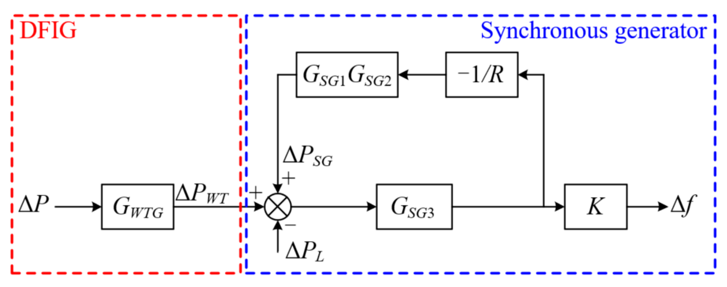
3.3. Local Stability Analysis of the Ehanced Frequency Response Strategy
As shown in
Section 3.2, the DFIG supports the system frequency using a constant Δ
P after detecting a disturbance.
Figure 6 shows a simplified diagram of a DFIG and a synchronous generator (SG) for the local stability analysis.
As in [
24],
GWTG in
Figure 6 is expressed as:
where
GWTG is a constant and set to 0.2 s.
As in [
25], the transfer function of the SG in
Figure 6 can be represented by:
where
GSG1(
s),
GSG2(
s), and
GSG3(
s) represent the transfer functions of the governor, prime mover, and rotating mass of the SG, respectively;
R is the droop gain of the SG and is set to 5%.
The transfer functions of
GSG1(
s),
GSG2(
s), and
GSG3(
s) are represented by:
where
TG is the time constant of the governor and is set to 0.1 s, and
TP is the time constant of the prime mover and is set to 0.3 s [
26];
α and
β are the angular momentum and damping coefficient of the SG and are set to 9.7 p.u. and 0 p.u., respectively [
27].
Thus, the transfer function from Δ
P to Δ
f can be expressed as:
Figure 7 shows the root locus of (16). Equation (16) contains four poles, which are −10.8, −4.99, −1.24 ± j2.19, respectively. Note that the poles of Equation (16) are located in the left half of the axis, therefore, we can deduce that the proposed enhanced frequency response strategy ensures the stable operation of the power system.
4. System Layout
Figure 8 illustrates a model system to explore the performance of the enhanced frequency response scheme. Such a model system comprises four synchronous generator (SGs), motor load, static load, and DFIG-based wind farms.
The synchronous generators (SGs) are: two 200-MVA SGs and two 150-MVA SGs. They are assumed to be steam turbine generators with the droop setting of 5.0%.
Figure 9 illustrates the configuration of the steam governor model [
4]. The settings of the inertia time constant of the SGs are 5.0 s for SG
1 and SG
2 and 4.3 s for SG
3 and SG
4, respectively [
26].
5. Case Studies
To study the effectiveness of the proposed enhanced frequency support scheme, three cases are carried out with various wind power penetrations and a low wind speed. The wind power penetration levels are 20% for Case 1 and 30% for Case 2. The wind speed is 7.0 m/s for Case 3. In this paper, the frequency support scheme based on the ROCOF and the frequency deviation control loops is denoted as the conventional frequency support strategy. The settings of the ROCOF and the frequency deviation control loops are 10 and 20, respectively.
5.1. Case 1: Wind Speed of 8.0 m/s, Wind Penetration of 20%, Disturbance of 100 MW
Figure 10 illustrates the simulation results for Case 1. When the DFIG operates in de-loaded operation without frequency response, the maximum ROCOF and frequency nadir are −0.766 Hz/s and 58.984 Hz, respectively, since there is no active power injection from the DFIG. The maximum ROCOF and the frequency nadir with the conventional frequency response are −0.734 Hz/s and 59.257 Hz, respectively, because an amount of active power is injected from the DFIG to the power grid. The frequency nadir and the maximum ROCOF with the proposed enhanced frequency response are improved to 59.396 Hz and −0.723 Hz/s, respectively, because more power is injected from the DFIG to the electric power system due to the suggested power reference (see
Figure 10a,b). Furthermore, the setting frequency with no frequency response, the conventional frequency response, and the proposed enhanced frequency response are 59.594 Hz, 59.607 Hz, and 59.610 Hz, respectively, since the power reference switches to the MPPT curve at operating point 3 (which is more than those of the other frequency responses.)
As shown in
Figure 10b, the output power of the enhanced frequency response increases the torque limit referred to power that is larger than the conventional frequency response so that the frequency nadir and the maximum ROCOF are better. Furthermore, the DFIG releases more energy so that the operating range of
ωr for the enhanced frequency response is wider, as illustrated in
Figure 10c.
5.2. Case 2: Wind Speed of 8.0 m/s, Wind Penetration of 30%, Disturbance of 100 MW
To investigate the scenario with high wind penetration, the SG2 is set to be out of service while the capacity of the DFIG-based wind farm increases to 150 MW. Since one SG is out of service, the system inertia and primary frequency response capability become low. As a result, the maximum ROCOF and the frequency nadir reduce to −0.823 Hz/s and 58.822 Hz, respectively, when no frequency response is implemented in the DFIG controller. For the conventional frequency response scheme and the proposed enhanced frequency support scheme, the frequency nadir increases to 59.297 Hz and 59.402 Hz/s, respectively, and the maximum ROCOF increases to −0.768 Hz/s and −0.754 Hz/s, respectively, due to the proposed power reference (see
Figure 11).
Furthermore, the setting frequencies with no frequency response, conventional frequency response, and proposed enhanced frequency support scheme are 59.539 Hz, 59.561 Hz, and 59.568 Hz, respectively, since the output power of the proposed enhanced frequency response is more than the others after supporting the frequency.
As shown in
Figure 11b, the output power of the enhanced frequency support scheme increases to the torque limit referred to power, which is larger than conventional frequency response so that the frequency nadir and maximum ROCOF are better. Furthermore, the DFIG releases more energy so that the rotor speed reduction for the enhanced frequency support scheme is larger, as illustrated in
Figure 11c.
As illustrated in
Figure 12, the proposed enhanced frequency support scheme effectively boosts the frequency response capability including the maximum ROCOF, frequency nadir, and settling frequency. Furthermore, with the growing penetration of wind power, the indices of the frequency support performance with no frequency response become worse, whereas the indices of the conventional and proposed frequency support schemes become better.
5.3. Case 3: Wind Speed of 7.0 m/s, Wind Penetration of 20%, Disturbance of 100 MW
To investigate the scenario with low wind speed, the wind speed is set to be 7.0 m/s.
Figure 13 displays the simulation results for Case 3. The frequency nadir of the no frequency response is 58.983 Hz, which is similar to Case 1 due to the same wind penetration and disturbance (see
Figure 8a and
Figure 13a). As displayed in
Figure 13a, the maximum ROCOF and the frequency nadir of the conventional frequency response strategy are −0.770 Hz/s and 59.260 Hz, respectively. Compared with the conventional frequency response scheme, the frequency nadir and the maximum ROCOF increase to 59.333 Hz and −0.761 Hz/s, respectively, using the proposed enhanced frequency support scheme. This is mainly because of the proposed power reference.
As shown in
Figure 13a, the setting frequencies for no frequency response, conventional frequency response, and proposed enhanced frequency support scheme are 59.594 Hz, 59.607 Hz, and 59.604 Hz, respectively. The reason for this phenomenon is that output power is more in the proposed enhanced frequency support and conventional frequency response schemes after supporting the frequency (see
Figure 13b).
The simulation results of Case 3 clearly demonstrate that the proposed enhanced frequency support scheme can also heighten the frequency nadir and the settling frequency and reduce the maximum ROCOF with more efficiency under low wind speed.
6. Conclusions
In this article, an enhanced frequency response strategy of the DFIG based on the over-speed de-loaded curve is proposed to boost the frequency response capability with more efficiency. To address this, a novel power function is employed and the DFIG operates at de-loading operation prior to the disturbance. The benefits of the enhanced frequency response strategy were investigated using a test system with various wind penetrations. The advantage of this strategy can be summarized as follows:
The DFIG operates at de-loading operation prior to the disturbance. Thus, the proposed enhanced frequency response strategy is able to leave a certain active power reserve for frequency events.
At the initial stage of a disturbance, the reference power increases to the torque limit at the de-load operating point using a novel power function and then decreases with the rotor speed toward the MPPT operating conditions. Thus, the proposed enhanced frequency response scheme can inject more energy into the grid and heighten the frequency nadir and settling frequency and reduce the ROCOF more effectively.
The simulation results of various wind penetrations clearly indicate that the proposed enhanced frequency response strategy effectively boosts the frequency response capability including the maximum ROCOF, frequency nadir, and settling frequency. However, for a high wind penetration, more active power is injected following a disturbance, and a slight second frequency dip is caused
For future research, the authors will focus on designing the suitable incremental power for various wind penetrations.
Author Contributions
Conceptualization, D.Y. and H.W.; methodology, D.Y.; software, Y.X. and D.Y.; validation, Y.X., D.Y. and H.W.; formal analysis, H.W.; investigation, Y.X., D.Y. and H.W.; resources, Y.X., D.Y.; data curation, Y.X., D.Y. and H.W.; writing—original draft preparation, Y.X. and D.Y.; writing—review and editing, All authors; visualization, D.Y.; supervision, H.W.; funding acquisition, D.Y. and H.W. All authors have read and agreed to the published version of the manuscript.
Funding
This research was funded by Natural Science Foundation of the Jiangsu Higher Education Institutions of China, grant number 20KJB470026.
Institutional Review Board Statement
Not applicable.
Informed Consent Statement
Not applicable.
Data Availability Statement
Not applicable.
Conflicts of Interest
The authors declare no conflict of interest.
References
- Bevrani, H. Real Power Compensation and Frequency Control. In Robus Power System Frequency Control; Springer: Berlin/Heidelberg, Germany, 2008; pp. 1–23. [Google Scholar]
- Yang, D.; Kim, J.; Kang, Y.C.; Muljadi, E.; Zhang, N.; Hong, J.; Song, S.-H.; Zheng, T. Temporary Frequency Support of a DFIG for High Wind Power Penetration. IEEE Trans. Power Syst. 2018, 33, 3428–3437. [Google Scholar] [CrossRef]
- Oshnoei, A.; Khezri, R.; Muyeen, S.; Blaabjerg, F. On the Contribution of Wind Farms in Automatic Generation Control: Review and New Control Approach. Appl. Sci. 2018, 8, 1848. [Google Scholar] [CrossRef] [Green Version]
- Yang, D.; Jin, Z.; Zheng, T.; Jin, E. An adaptive droop control strategy with smooth rotor speed recovery ca-pability for type III wind turbine generators. Int. J. Electr. Power Energy Syst. 2022, 135, 107532. [Google Scholar] [CrossRef]
- Hydro Québec TransÉnergie. Transmission Provider Technical Requirements for the Connection of Power Plants to the Hydro Québec Transmission System; Hydro Quebec: Montréal, QC, Canada, 2009. [Google Scholar]
- Yang, D.; Jin, Z.; Zheng, T.; Jin, E.; Zhang, X.; Hua, L. Frequency control scheme with dynamic droop characteristics of a DFIG for mitigating the frequency fluctuations. Int. Trans. Electr. Energy Syst. 2021, e13044. [Google Scholar] [CrossRef]
- Kim, J.; Muljadi, E.; Gevorgian, V.; Hoke, A.F. Dynamic Capabilities of an Energy Storage-Embedded DFIG System. IEEE Trans. Ind. Appl. 2019, 55, 4124–4134. [Google Scholar] [CrossRef]
- Mahrouch, A.; Ouassaid, M. Primary Frequency Regulation of Isolated Microgrid based on Three-Dimensional Fuzzy Logic Control for Deloaded PMSG Enhanced by Diesel Generator. In Proceedings of the 2020 International Conference on Electrical and Information Technologies (ICEIT), Rabat, Morocco, 4–7 March 2020; Institute of Electrical and Electronics Engineers (IEEE): New York, NY, USA, 2020; pp. 1–6. [Google Scholar]
- Morren, J.; De Haan, S.W.H.; Kling, W.L.; Ferreira, J.A. Wind Turbines Emulating Inertia and Supporting Primary Frequency Control. IEEE Trans. Power Syst. 2006, 21, 433–434. [Google Scholar] [CrossRef]
- Ramtharan, G.; Jenkins, N.; Ekanayake, J. Frequency support from doubly fed induction generator wind turbines. IET Renew. Power Gener. 2007, 1, 3–9. [Google Scholar] [CrossRef]
- Margaris, I.D.; Papathanassiou, S.A.; Hatziargyriou, N.D.; Hansen, A.D.; Sørensen, P.E. Frequency Control in Autonomous Power Systems with High Wind Power Penetration. IEEE Trans. Sustain. Energy 2012, 3, 189–199. [Google Scholar] [CrossRef]
- Attya, A.; Domínguez-García, J.L.; Anaya-Lara, O. A review on frequency support provision by wind power plants: Current and future challenges. Renew. Sustain. Energy Rev. 2018, 81, 2071–2087. [Google Scholar] [CrossRef] [Green Version]
- Žertek, A.; Verbič, G.; Pantoš, M. Optimised control approach for frequency-control contribution of variable speed wind turbines. IET Renew. Power Gener. 2012, 6, 17–23. [Google Scholar] [CrossRef]
- Zertek, A.; Verbic, G.; Pantos, M. A Novel Strategy for Variable-Speed Wind Turbines’ Participation in Primary Frequency Control. IEEE Trans. Sustain. Energy 2012, 3, 791–799. [Google Scholar] [CrossRef]
- Gomez, L.A.G.; Lourenço, L.F.N.; Salles, M.B.C.; Grilo, A.P.; Sguarezi, A. Frequency Support of Grid Connected Wind Turbine Based-DFIG. In Proceedings of the 2019 International Conference on Clean Electrical Power (ICCEP), Otranto, Italy, 2–4 July 2019; pp. 645–650. [Google Scholar] [CrossRef]
- Anju, P.K.; Zarina, P.P. Frequency Regulation by Doubly Fed Induction Generator. In Proceedings of the 2019 IEEE International Conference on Electrical, Computer and Communication Technologies (ICECCT), Coimbatore, India, 20–22 February 2019; Institute of Electrical and Electronics Engineers (IEEE): New York, NY, USA, 2019; pp. 1–4. [Google Scholar]
- Zhong, C.; Lv, Y.; Zhou, Y.; Li, H. An Equivalent Rotor Speed Compensation Control of PMSG-Based Wind Turbines for Frequency Support in Islanded Microgrids. Front. Energy Res. 2021, 9. [Google Scholar] [CrossRef]
- Fernández-Muñoz, D.; Perez-Diaz, J.I.; Guisandez, I.; Chazarra, M.; Fernandez-Espina, A. Fast frequency control ancillary services: An international review. Renew. Sustain. Energy Rev. 2020, 120, 109662. [Google Scholar] [CrossRef]
- Yang, P.; He, B.; Wang, B.; Dong, X.; Liu, W.; Zhang, J.; Wu, Z.; Liu, J.; Qin, Z. Coordinated control of rotor kinetic energy and pitch angle for large-scale doubly fed induction generators participating in system primary frequency regulation. IET Renew. Power Gener. 2021, 15, 1836–1847. [Google Scholar] [CrossRef]
- Lyu, X.; Jia, Y.; Xu, Z. A Novel Control Strategy for Wind Farm Active Power Regulation Considering Wake Interaction. IEEE Trans. Sustain. Energy 2019, 11, 618–628. [Google Scholar] [CrossRef]
- Bianchi, F.D.; Mantz, R.J.; De Battista, H. Wind Turbine Control Systems; Springer: Berlin/Heidelberg, Germany, 2007. [Google Scholar]
- Liu, X.; Xu, Z.; Zhao, J. Combined Primary Frequency Control Strategy of Permanent Magnet Synchronous Generator-Based Wind Turbine. Electr. Power Components Syst. 2018, 46, 1704–1718. [Google Scholar] [CrossRef]
- Kheshti, M.; Ding, L.; Nayeripour, M.; Wang, X.; Terzija, V. Active power support of wind turbines for grid frequency events using a reliable power reference scheme. Renew. Energy 2019, 139, 1241–1254. [Google Scholar] [CrossRef]
- Mauricio, J.M.; Marano-Marcolini, A.; Gomez-Exposito, A.; Ramos, J.L.M. Frequency Regulation Contribution Through Variable-Speed Wind Energy Conversion Systems. IEEE Trans. Power Syst. 2009, 24, 173–180. [Google Scholar] [CrossRef]
- Wood, A.J.; Wollenberg, B.F. Power Generation, Operation and Control, 2nd ed.; Wiley: New York, NY, USA, 1996. [Google Scholar]
- Byerly, R.T.; Aanstad, O.; Berry, D.H.; Dunlop, R.D.; Ewart, D.N.; Fox, B.M.; Johnson, L.H.; Tschappat, D.W. Dynamic models for steam and hydro turbines in power system studies. IEEE Trans. Power App. Syst. 1973, PAS-92, 1904–1915. [Google Scholar]
- Electromagnetic Transient Program, EMTP-RV, CEA Technologies, Inc. 2016. Available online: http://www.emtp-software.com (accessed on 15 November 2019).
| Publisher’s Note: MDPI stays neutral with regard to jurisdictional claims in published maps and institutional affiliations. |
© 2021 by the authors. Licensee MDPI, Basel, Switzerland. This article is an open access article distributed under the terms and conditions of the Creative Commons Attribution (CC BY) license (https://creativecommons.org/licenses/by/4.0/).


